Simoco EMEA SB2K5354D3D3V SB2025NT Base Station User Manual Manual
Simoco EMEA Ltd SB2025NT Base Station Manual
Manual

SB2025NT BASE STATION
TECHNICAL AND USER MANUALS
SGD-SB2025NT-TUM
Issue –1.0
REVISION 1.0
DATE January 2012
PREPARED BY PJ
APPROVED JW
POSITION Dev. Eng.
Team Simoco Ltd.
Field House,
Uttoxeter Old Road
Derby
DE1 1NH
Tel: +44 (0) 1332 375500
FAX: +44 (0) 1332 375501
http://www.teamsimoco.com
ComGroup Australia Pty Ltd.
1270 Ferntree Gully Road,
Scoresby
Victoria, 3179
Australia
Tel: +61 (0)3 9730 3999
FAX: +61 (0)3 9730 3988
http://www.comgroup.net.au
©Simoco 2012

SGD-SB2025NT-TUM
Jan 12 Page ii PREFACE
PREFACE
D
ECLARATION
This Manual covers the SB2025NT Base Station. It is broken down into two parts: Part 1 is the
Technical Manual for the base station; and Part 2 is the User Manual for the Engineering Terminal
(ET).
Any performance figures quoted are subject to normal manufacturing and service tolerances. The
right is reserved to alter the equipment described in this manual in the light of future technical
development.
Changes or modifications not expressly approved by the party responsible for compliance could
void the user’s authority to operate the equipment.
NOTE.
The manufacturer is not responsible for any radio or television interference caused by
unauthorized modifications to this equipment. Such modifications could void the
user’s authority to operate the equipment.
C
OPYRIGHT
All information contained in this document is the property of Simoco. All rights are reserved. This
document may not, in whole or in part, be copied, photocopied, reproduced, translated, stored, or
reduced to any electronic medium or machine-readable form, without prior written permission from
Simoco.
D
ISCLAIMER
There are no warranties extended or granted by this document. Simoco accepts no responsibility
for damage arising from use of the information contained in the document or of the equipment and
software it describes. It is the responsibility of the user to ensure that use of such information,
equipment and software complies with the laws, rules and regulations of the applicable
jurisdictions.
E
QUIPMENT AND
M
ANUAL
U
PDATES
In the interests of improving the performance, reliability or servicing of the equipment, Simoco
reserves the right to update the equipment or this document or both without prior notice.
E
RRORS AND
O
MISSIONS
The usefulness of this publication depends upon the accuracy and completeness of the information
contained within it. Whilst every endeavour has been made to eliminate any errors, some may still
exist. It is requested that any errors or omissions noted should be reported to either of the
following who are part of the Simoco group:
Team Simoco Ltd.
Field House
Uttoxeter Old Road
Derby
DE1 1NH
UK
ComGroup
1270 Ferntree Gully Road
Scoresby
Victoria
3179
Australia
Tel: +44 (0) 871 741 1050 Tel: +61 (0)3 9730 3800
E-mail: customerservice@teamsimoco.com E-mail: comgroup@comgroup.net.au

SGD-SB2025NT-TUM
Jan 12 Page iii PREFACE
D
OCUMENT
H
ISTORY
Issue Date Comments
0.1 December 2011 First Draft Issue. Distributed for comment.
1.0 January 2012 Initial Issue.
R
ELATED
D
OCUMENTS
Nil.

SGD-SB2025NT-TUM
Jan 12 Page iv CONTENTS
TABLE OF CONTENTS
Page
Title Page ....................................................................................................................................... i
Preface .......................................................................................................................................... ii
Table of Contents (this list) ........................................................................................................ iv
PERSONAL SAFETY .................................................................................................................... v
EQUIPMENT SAFETY ................................................................................................................. vii
WEEE Notice ............................................................................................................................. viii
General Notes ............................................................................................................................. ix
Support – Contact Information ................................................................................................... x
Abbreviations ............................................................................................................................. xii
Glossary ..................................................................................................................................... xv
PART
1. SB2025NT
T
ECHNICAL
M
ANUAL
.
PART
2. E
NGINEERING
T
ERMINAL
U
SER
M
ANUAL
.

SGD-SB2025NT-TUM
Jan 12 Page v WARNINGS
PERSONAL SAFETY
Safety Precautions
These Safety Precautions, Warnings and Cautions advise personnel of specific hazards which may
be encountered during the procedures contained in this document and that control measures are
required to prevent injury to personnel, and damage to equipment and/or the environment.
Before commencing the installation or any maintenance of this equipment, personnel are to
acquaint themselves with all risk assessments relevant to the work site and the task. They must
then comply with the control measures detailed in those risk assessments.
References covering safety regulations, health hazards and hazardous substances are detailed
under the WARNINGS section below. These are referred to in the tasks, when encountered.
Adequate precautions must be taken to ensure that other personnel do not activate any equipment
that has been switched off for maintenance. Refer to the Electricity at Work regulations 1992.
Where dangerous voltages are exposed during a task, safety personnel are to be provided as
detailed in the Electricity at Work regulations 1992. Where safety personnel are required for any
other reason, management are to ensure that the personnel detailed are aware of the hazard and
are fully briefed on the action to be taken in an emergency.
Where equipment contains heavy components or units that require lifting, lowering, pulling or
pushing operations to be performed on them during maintenance tasks, all managers and
tradesmen are to be conversant with the Manual Handling Operations Regulations 1992, ISBN
0110259203.
Hazardous Substances
Before using any hazardous substance or material, the user must be conversant with the safety
precautions and first aid instructions:
• On the label of the container in which it was supplied.
• On the material Safety Data Sheet.
• In any local Safety Orders and Regulations.
WARNINGS
Radio Frequency Radiation
WARNING
RADIO FREQUENCY (RF) RADIATION. A RF RADIATION HAZARD
EXISTS IN THIS EQUIPMENT. TO AVOID RF INJURY, DO NOT TOUCH
THE ANTENNA WHEN THE TRANSMITTER (TX) IS IN USE. DO NOT
OPERATE TX WITH ANTENNA DISCONNECTED. REFER TO EU
DIRECTIVE 2004/40/EC DATED 29 APRIL 2004.
WARNING
THERMAL OR RF BURNS. DO NOT ATTEMPT INTERNAL SERVICING
WHILE TRANSMITTING. THERMAL OR RF BURNS MAY RESULT FROM
TOUCHING CERTAIN COMPONENTS WITHIN THE POWER AMPLIFIER
MODULE WHILE TRANSMITTING OR OPERATING THE TX.
SGD-SB2025NT-TUM
Jan 12 Page vi WARNINGS
Dangerous Voltages
Although there are no mains voltages present within the equipment, other voltages do exist in the
equipment. The following general safety precautions as would normally apply, should be observed
during all phases of operation, service and repair of this equipment.
WARNING
TO MINIMISE ANY POSSIBLE SHOCK HAZARD FROM AN EXTERNAL
POWER SUPPLY OR LIGHTNING STRIKE, THE CHASSIS OF THE
EQUIPMENT CABINET MUST TO BE CONNECTED TO AN ELECTRICAL
SAFETY EARTH CONNECTION.
WARNING
DO NOT OPERATE IN AN EXPLOSIVE ATMOSPHERE.
DO NOT OPERATE THIS EQUIPMENT IN THE PRESENCE OF
FLAMMABLE GASES OR FUMES. OPERATION OF ANY ELECTRICAL
EQUIPMENT IN SUCH AN ENVIRONMENT CONSTITUTES A DEFINITE
SAFETY HAZARD.
WARNING
DO NOT SUBSTITUTE PARTS OR MODIFY THE EQUIPMENT.
BECAUSE OF THE DANGER OF INTRODUCING ADDITIONAL HAZARDS,
DO NOT INSTALL SUBSTITUTE OR LOWER VOLTAGE PARTS TO THE
EQUIPMENT. RETURN TO YOUR AUTHORISED DISTRIBUTOR.
Beryllium and Beryllia
WARNING
BERYLLIUM AND BERYLLIA. MOST RF POWER TRANSISTORS AND
SOME RF POWER HYBRIDS CONTAIN BERYLLIUM OXIDE. REFER TO
THE CONTROL OF SUBSTANCES HAZARDOUS TO HEALTH
REGULATIONS (COSHH) 2002 AND/OR THE APPROPRIATE SAFETY
DATA SHEET. CONSULT YOUR LOCAL AUTHORITY FOR CORRECT
DISPOSAL THEREOF.
SGD-SB2025NT-TUM
Jan 12 Page vii WARNINGS
EQUIPMENT SAFETY
Installation and Maintenance
The SB2025NT Series of base stations should only be installed and maintained by qualified
personnel.
Cautions
CAUTION
The Antenna System must to be protected against lightning by means of an
earthing system and surge protection device.
Do not connect Antenna Lightning conductors to the base station or Mains
Earth.
Maintenance Precautions
CAUTION
Electrostatic Discharge Sensitive Devices (ESDS Devices). This equipment
contains ESDS Devices, the handling procedures detailed in BS EN 61340-5-
1:2007 or ANSI/ESD S20.20-1999 are to be observed.
WARRANTY CONDITIONS AND PRECAUTIONS
The following conditions are not covered by the warranty of the SB2025. Please ensure that the
SB2025 is not subject to:
1. Over voltage or Reverse Power Supply Voltage.
2. Operation in locations subject to abnormal environmental conditions such as extreme
temperatures or ingress of moisture.
3. Operation of the SB2025 Tx output into an open or short circuit or an incorrectly terminated
load.

SGD-SB2025NT-TUM
Jan 12 Page viii WEEE NOTICE
WASTE ELECTRICAL AND ELECTRONIC EQUIPMENT (WEEE)
NOTICE
The Waste Electrical and Electronic Equipment (WEEE) Directive became law
in most EU countries during 2005. The directive applies to the disposal of
waste electrical and electronic equipment within the member states of the
European Union.
As part of the legislation, electrical and electronic equipment will feature the
crossed out wheeled bin symbol (see image at left) on the product or in the
documentation to show that these products must be disposed of in accordance
with the WEEE Directive.
In the European Union, this label indicates that this product should not be disposed of with
domestic or “ordinary” waste. It should be deposited at an appropriate facility to enable recovery
and recycling.

SGD-SB2025NT-TUM
Jan 12 Page ix GENERAL NOTES
GENERAL NOTES
M
ANUAL
C
OMPILATION
This manual provides detailed information on the SB2025NT base station. It is divided into two
parts.
Part 1 – Technical Manual
Part 1 is the Technical Manual, which includes information on Installation and Operation, General
Description, Technical Description, Alignment and Testing, Fault Finding and Drawings for the
base stations.
Details of both “basic” and “optional units” have been included in the Technical Manual, therefore,
some material may not be relevant to every system. Configuration is dependent upon the
specification by the customer when the equipment was ordered and installed.
The manual has been compiled with a two-tier maintenance policy in mind, i.e. first-line fault
location and repair by replacement, followed by subsequent bench-testing of sub-assemblies to
specification. Consequently, some “overlap” and/or duplication of information has resulted.
Part 2 – User Manual
Part 2 is the User Manual for the ET software application. The ET is the primary source for
controlling, configuring and monitoring the Solar 2 Modules fitted within the SB2025 series of base
stations.
P
AGINATION
Each part of the manual is divided into a number of sections, each section deals with one aspect of
the system.
Following initial issue, any page that has been amended or updated will also bear an updated
reference.
P
ARTS
L
ISTING
A Composite List of Replaceable Assemblies (i.e. a list of all components used in the system) is
included at Part 1, Section 9.

SGD-SB2025NT-TUM
Jan 12 Page x SUPPORT
DISTRIBUTORS
Australia
ComGroup Australia Pty Ltd.
Scoresby, Vic
www.comgroup.net.au
Tel: +61 (0)3 9730 3999
Fax: +61 (0)3 9730 3988
comgroup@comgroup.net.au
United Kingdom
Team Simoco Ltd
Field House, Uttoxeter Old Road
Derby, DE1 1NH, England
Tel: +44 (0) 1332 375 500
Fax: +44 (0) 1332 375 401
customerservice@teamsimoco.com
CONTACT INFORMATION
At Simoco we welcome your comments, feedback and suggestions. Departmental contacts for
both Team Simoco and ComGroup, which are part of the Simoco group, have been provided for
your quick reference below.
TECHNICAL SUPPORT
Technical Support services to assist in resolving any malfunctions or other technical issues are as
follows.
C
OM
G
ROUP
(A
USTRALIA
)
Technical Help Desk
Tel: Within Australia: 1300 36 36 07
International: +61 (0)3 9730 3800
Fax: +61 (0)3 9730 3968
E-mail: simoco@simoco.com.au
T
EAM
S
IMOCO
(UK)
Technical Support Helpline
Tel: +44 (0) 871 741 1040
E-mail: techsupport@teamsimoco.com

SGD-SB2025NT-TUM
Jan 12 Page xi SUPPORT
SALES & SERVICE ENQUIRES
For information regarding distributor agreements, general product and pricing information, contact
Simoco’s Account Management Teams.
C
OM
G
ROUP
(A
USTRALIA
)
Tel: Within Australia: 1300 36 36 07
International: +61 (0)3 9730 3800
Fax: +61 (0)3 9730 3988
E-mail: simoco@simoco.com.au
T
EAM
S
IMOCO
(UK)
Customer Services
Tel: +44 (0) 871 741 1050
Fax: +44 (0) 871 741 1051
E-mail: customerservice@teamaimoco.com
Sales
E-mail sales@teamsimoco.com
Marketing
For general corporate information, marketing programmes, public relations and other general
questions.
E-mail marketing@teamsimoco.com

SGD-SB2025NT-TUM
Jan 12 Page xii ABBREVIATIONS
ABBREVIATIONS
The following abbreviations are used throughout this document. Wherever practicable, whenever
the abbreviation is first used, the full meaning is given with the abbreviation in parenthesis, after
that only the abbreviation will be used.
Abbreviation Meaning
1PPS One Pulse Per Second (timing signal)
1U One Unit
AC Alternating Current
Ae Aerial/Antenna
AFSI Analogue Fixed Station Interface
AMBE+2 Advanced Multi-Band Excitation+2
BER Bit Error Rate
BNC Bayonet Neill-Concelman
C4FM Continuous 4 Level Frequency Modulation
CDCSS Continuous Digital Coded Squelch System
CMOS Complementary Metal Oxide Semiconductor
COR Carrier Operated Relay
COSHH Control Of Substances Hazardous to Health
csv comma separated variables
CTCSS Continuous Tone Coded Squelch System
CTS Communications Test Set
DC Direct Current
DCS Digital Coded Squelch
DFSI Digital Fixed Station Interface
DHCP Dynamic Host Configuration Protocol
DIP Dual In-line Package
DSP Digital Signals Processor
EEPROM Electrically Erasable Programmable Read Only Memory
EEROM Electrically Erasable Read Only Memory
EMI Electromagnetic Interference
EPROM Erasable Programmable Read-Only Memory
ESDS Devices Electrostatic Discharge Sensitive Devices
ET Engineering Terminal
FET Field Effect Transistor
FFSK Fast Frequency Shift Keying
FM Frequency Modulation
FW FirmWare
GPS Global Positioning System
ID IDentification
IF Intermediate Frequency
I/O Input/Output
IP Internet Protocol
I/P Input
LDMOS Laterally Diffused Metal Oxide Semiconductor
LED Light Emitting Diode
MDR Mini Data Ribbon

SGD-SB2025NT-TUM
Jan 12 Page xiii ABBREVIATIONS
Abbreviation Meaning
MIB Management Information Base
MMIC Monolithic Microwave Integrated Circuit
MTBF Mean Time Between Failure
NAC Network Access Code
NC Not Connected
NI Network Interface
NMEA National Marine Electronics Association
NMS Network Management System
OEM Original Equipment Manufacturer
OIDs Object IDentifiers
O/P Output
PA Power Amplifier
PAT Packet Arrival Time
PC Personal Computer
PCB Printed Circuit Board
PIC Programmable Intelligent Computer
PLL Phase Locked Loop
PMR Private Mobile Radio
PSL Peak System Level
PSU Power Supply Unit
PTT Press (Push) To Talk
PWM Pulse Width Modulation
RAM Random Access Memory
R&TTE Radio and Telecommunications Terminal Equipment
RF Radio Frequency
RFI Radio Frequency Interference
RSSI Received Signal Strength Indicator
RTN Return
RTS Radio Test Set
Rx Receive, Receiver
SBC Signal Board Computer
SINAD SIgnal to Noise and Distortion
SNMP Simple Network Management Protocol
SNR Signal to Noise Ratio
TCXO Temperature Controlled Crystal Oscillator
TGID Talk Group IDentification
TIA Telecommunications Industry Association
TM Traffic Manager
TOT Total Output Time
TRC Tone Remote Control
T/T TalkThrough
TTL Transistor Transistor Logic
Tx Transmit, Transmitter
UART Universal Asynchronous Receiver/Transmitter
UHF Ultra High Frequency
USB Universal Serial Bus

SGD-SB2025NT-TUM
Jan 12 Page xiv ABBREVIATIONS
Abbreviation Meaning
UTC Universal Time Coordinated
VCO Voltage Controlled Oscillator
VF Voice Frequency
VHF Very High Frequency
VoIP Voice over Internet Protocol
VSWR Voltage Standing Wave Ratio
WEEE Waste Electrical and Electronic Equipment

SGD-SB2025NT-TUM
Jan 12 Page xv GLOSSARY
GLOSSARY OF TERMS
The following terms are used through out this document.
Term Meaning
‘……’ Reference to a setting or feature (exactly as it is displayed) that may be
selected or enabled either directly or through a software application, e.g.
‘Button’, ‘Control’, ‘Switch’.
0 V The internal negative supply line to which the internal circuitry is referenced.
1PPS A One Pulse Per Second timing signal (timed from the leading or rising edge).
Audio
Frequency A composite audio band signal that may include tones.
CTCSS A sub-audio tone used for validating a received signal (also known as a PL
tone).
Closed
Contact Connects to the common or pole contact when a relay is not energised (off).
Firmware The embedded code that makes SB2025 function.
Ground/Gnd A connection that is the same potential as the chassis or case (earth).
Go/GO A signal that flows towards the base station Tx.
In A signal that is entering the SB2025 base station.
Key/Keyed A signal that can cause transmit mode or the transmit condition itself.
Loader The software application used to install the Programmable Intelligent
Computer (PIC) Firmware.
Open Contact Connects to the common or pole contact when a relay is energised (on).
Out A signal that is leaving the SB2025 base station.
PAT Packet Arrival Time – a value indicating the network latency.
Press To Talk The action or signal that causes the equipment to be placed into transmit
mode or to be keyed.
RS422 A balanced/differential line serial data signal.
Return/RTN A signal that flows from the base station Rx (receive).
SELV Safety Extra Low Voltage – within the definition used by EN60950.
Sig/Signalling A state or tone that is used to indicate a defined condition.
TTL A logic signal where a ‘Low’ is represented by a voltage of less than 0.7 V and
a ‘High’ by a voltage >3 V but ≤5 V.
Vote/voting The selection of the best received signal from a collection of signals presented
individually and simultaneously.

SGD-SB2025NT-TUM
Jan 12 Page xvi GLOSSARY
Intentionally left blank.
PART 1
SB2025NT TECHNICAL MANUAL

SGD-SB2025NT-TUM, Part 1
Jan 12 Page 3 CONTENTS
PART 1
TABLE OF CONTENTS
Page
Table of Contents (this list) ......................................................................................................... 3
List of Figures .............................................................................................................................. 6
List of Tables ................................................................................................................................ 7
1
INTRODUCTION ................................................................................................................... 9
1.1
SB2025
A
PPLICATIONS
...................................................................................................... 9
1.2
S
OLAR
2
–
B
RIEF
D
ESCRIPTION
........................................................................................... 9
1.2.1
Method of Operation .............................................................................................. 10
1.2.2
Basic I/O Facility .................................................................................................... 10
1.2.3
PMR Wide-Area Cover Facilities ............................................................................ 10
1.3
S
OLAR
2
–
S
TYLE
............................................................................................................. 10
1.4
S
OLAR
2
P25 ................................................................................................................... 11
2
SPECIFICATIONS............................................................................................................... 13
2.1
G
ENERAL
S
PECIFICATIONS
................................................................................................ 13
2.2
T
RANSMITTER
S
PECIFICATIONS
......................................................................................... 13
2.3
R
ECEIVER
S
PECIFICATIONS
............................................................................................... 13
2.4
P25
(APCO-25)
S
PECIFICATIONS
...................................................................................... 14
3
INSTALLATION AND OPERATION.................................................................................... 15
3.1
I
NSTALLATION
.................................................................................................................. 15
3.2
O
PERATION
...................................................................................................................... 16
3.2.1
MxTools Utility........................................................................................................ 16
3.2.2
Setting to Work....................................................................................................... 16
3.2.2.1
Setting Micro Controller Jumpers .................................................................. 16
3.2.2.2
Select Operating Mode ................................................................................. 17
3.2.2.3
Select Operating Channel ............................................................................. 18
3.2.2.4
Configure Alarms/M Lead.............................................................................. 18
3.2.2.5
Configure Digital I/O...................................................................................... 18
3.2.3
Adjustments ........................................................................................................... 19
4
GENERAL DESCRIPTION .................................................................................................. 20
4.1
P
HYSICAL
D
ESCRIPTION
.................................................................................................... 20
4.1.1
Front Panel ............................................................................................................ 21
4.1.1.1
LED Indicators .............................................................................................. 22
4.1.1.2
Traffic Manager LED Indicator....................................................................... 22
4.1.1.3
Network Interface LED Indicator.................................................................... 22
4.1.1.4
USB Connector ............................................................................................. 23
4.1.2
Rear Panel ............................................................................................................. 23
4.1.2.1
GPS (1PPS Timing Signal Input)................................................................... 24
4.1.2.2
Environment I/O ............................................................................................ 24
4.1.2.3
DC Power Input............................................................................................. 24
4.1.2.4
Transmitter Output ........................................................................................ 24
4.1.2.5
Receiver Input............................................................................................... 25
4.1.2.6
High Stability Oscillator Input (BNC).............................................................. 25
4.1.2.7
Ethernet ........................................................................................................ 25

SGD-SB2025NT-TUM, Part 1
Jan 12 Page 4 CONTENTS
4.1.3
Connector Pin-outs ................................................................................................ 25
4.1.3.1
Environment I/O ............................................................................................ 25
4.1.3.2
GPS (1PPS Timing Signal Input)................................................................... 25
4.1.3.3
DC Power Input............................................................................................. 26
4.1.3.4
Ethernet ........................................................................................................ 26
4.2
E
NVIRONMENT
I/O
O
VERVIEW
............................................................................................ 27
4.2.1
Inputs and Outputs................................................................................................. 27
4.2.2
Input ‘Polarity’ ........................................................................................................ 27
4.2.3
Output ‘Polarity’...................................................................................................... 27
4.2.4
Electrical Constraints.............................................................................................. 27
4.3
M
ODULE
F
UNCTIONAL
D
ESCRIPTION
.................................................................................. 28
4.3.1
Exciter Module ....................................................................................................... 28
4.3.2
Receiver Module .................................................................................................... 28
4.3.3
Power Amplifier Module ......................................................................................... 28
4.3.4
Micro Controller Board ........................................................................................... 29
4.3.5
Network Interface ................................................................................................... 29
4.3.6
ITX ......................................................................................................................... 29
4.3.7
Compact Flash....................................................................................................... 29
4.3.8
SBC Support PCB.................................................................................................. 30
4.3.9
Aux PCB ................................................................................................................ 30
4.3.10
Pico PSU................................................................................................................ 30
5
TECHNICAL DESCRIPTION............................................................................................... 31
5.1
E
XCITER
M
ODULE
............................................................................................................. 31
5.2
R
ECEIVER
M
ODULE
........................................................................................................... 31
5.3
P
OWER
A
MPLIFIER
M
ODULE
.............................................................................................. 32
5.3.1
Wide Band PA (50 Watt Model).............................................................................. 32
5.3.2
Wide Band PA (100 Watt Model)............................................................................ 32
5.4
M
ICRO
C
ONTROLLER
B
OARD
............................................................................................ 33
5.4.1
Overall Radio Management.................................................................................... 33
5.4.2
Tx Signal Processing.............................................................................................. 34
5.4.3
Rx Signal Processing ............................................................................................. 34
5.4.4
RF Power Control................................................................................................... 35
5.4.5
User Interface ........................................................................................................ 35
5.5
S
OLAR
T
RAFFIC
M
ANAGER
............................................................................................... 35
5.6
S
OLAR
N
ETWORK
I
NTERFACE
............................................................................................ 36
6
ALIGNMENT AND TESTING .............................................................................................. 38
6.1
T
RANSCEIVER
S
ETUP
,
C
ALIBRATION AND
A
LIGNMENT
........................................................ 38
6.1.1
Sending Model Number and Serial Number to the Radio ....................................... 38
6.1.2
Sending Configuration Information ......................................................................... 39
6.1.3
Sending Channel Information................................................................................. 39
6.1.4
Setting Alignment Channel..................................................................................... 39
6.1.5
Power Calibration................................................................................................... 39
6.1.6
RSSI Calibration..................................................................................................... 40
6.1.7
Temperature Calibration......................................................................................... 40
6.1.8
Tx Power Adjustment ............................................................................................. 40
6.1.9
Peak Deviation and Modulation Balance Configuration .......................................... 41
6.1.9.1
Station NI/SB2025......................................................................................... 41

SGD-SB2025NT-TUM, Part 1
Jan 12 Page 5 CONTENTS
6.1.10
Mute Threshold Setting .......................................................................................... 50
6.2
M
ODULE
L
EVEL
T
EST
P
ROCEDURES
.................................................................................. 52
6.2.1
Exciter Module ....................................................................................................... 52
6.2.2
Receiver Module .................................................................................................... 53
6.2.3
Power Amplifier Module ......................................................................................... 55
6.2.4
VCO Board............................................................................................................. 56
6.2.5
Microcontroller Module........................................................................................... 57
7
FAULT FINDING PROCEDURES ....................................................................................... 58
7.1
SB2025
B
ASE
S
TATION
.................................................................................................... 58
7.1.1
Transmitter Section ................................................................................................ 58
7.1.2
Receiver Section .................................................................................................... 59
7.2
M
ICRO
C
ONTROLLER
PCB ................................................................................................ 59
7.3
R
ECEIVER
M
ODULE
........................................................................................................... 60
7.3.1
VCO Locking.......................................................................................................... 60
7.3.2
Rx Front End.......................................................................................................... 60
7.3.3
IF Section............................................................................................................... 60
7.4
E
XCITER
M
ODULE
............................................................................................................. 61
7.4.1
VCO Locking.......................................................................................................... 61
7.4.2
RF Power............................................................................................................... 61
7.5
P
OWER
A
MPLIFIER
............................................................................................................ 61
8
DRAWINGS......................................................................................................................... 63
8.1
C
URRENT
D
RAWINGS
........................................................................................................ 63
9
SPARES.............................................................................................................................. 71
APPENDICES
A SB2025 Frequency Bands.
B Channel Select DIP Switch Settings.
C Configuration Procedure Cable Requirements.
D SB2025 Micro Controller PCB Link Settings.

SGD-SB2025NT-TUM, Part 1
Jan 12 Page 6 CONTENTS
LIST OF FIGURES
Page
Figure 1. SB2025NT Top and Rear Views. .................................................................................. 21
Figure 2. SB2025NT Front Panel. ................................................................................................ 21
Figure 3. SB2025NT Rear Panel.................................................................................................. 23
Figure 4. SB2025NT Block Diagram. ........................................................................................... 37
Figure 5. HyperTerminal – Menu.................................................................................................. 42
Figure 6. NI ET – Audio Mode to ‘Remote’................................................................................... 43
Figure 7. NI Engineering – Main Audio tab, ‘In Audio Sensitivity’ settings. ................................... 44
Figure 8. NI Engineering – Facilities tab, Test Tone settings........................................................ 45
Figure 9. NI Engineering – Signalling tab, Manual Trigger. .......................................................... 45
Figure 10. MxTools – Set Software Channel to tick button. .......................................................... 46
Figure 11. NI Engineering – Facilities tab, Test Tone Frequency. ................................................ 47
Figure 12. MxTools – Channel Edit page. .................................................................................... 47
Figure 13. Typical result for Tx Modulation displayed on RTS...................................................... 48
Figure 14. Rx Component Overlay............................................................................................... 64
Figure 15. Exciter Component Overlay. ....................................................................................... 64
Figure 15. Exciter Component Overlay. ....................................................................................... 65
Figure 16. PA Component Overlay – Superseded Version........................................................... 65
Figure 16. PA Component Overlay – Superseded Version........................................................... 66
Figure 17. PA Component Overlay – New Wide Band PA Version............................................... 67
Figure 18. Micro Controller Component Overlay (Rev S). ............................................................ 68
Figure 19. Tx and Rx VCO Component Overlay Bands A to Q3................................................... 69
Figure 20. Tx and Rx VCO Component Overlay Bands R to X..................................................... 69
Figure 21. HP Rx VCO Component Overlay Bands A to Q. ......................................................... 70
Figure 22. Tx/Rx V3 VCO Component Overlay. ........................................................................... 70
Figure C-1. T36 Module Serial Cable – wiring details................................................................... 75
Figure D-1. Micro Controller Jumper and Link locations............................................................... 77

SGD-SB2025NT-TUM, Part 1
Jan 12 Page 7 CONTENTS
LIST OF TABLES
Page
Table 1. General Specifications. .................................................................................................. 13
Table 2. Transmitter Specifications. ............................................................................................. 13
Table 3. Receiver Specifications.................................................................................................. 13
Table 4. Functions and Default Positions of the Micro Controller Jumpers................................... 16
Table 5. DIP Switch 2 Settings..................................................................................................... 18
Table 6. SB2025NT LED Functions. ............................................................................................ 22
Table 7. TM Status Indicator. ....................................................................................................... 22
Table 8. NI Status Indicator.......................................................................................................... 23
Table 9. Rear Panel Connections. ............................................................................................... 24
Table 10. 20-way MDR Socket – Environment I/O. ...................................................................... 25
Table 11. 15-way D Socket – GPS/1PPS Timing Signal. ............................................................. 26
Table 12. DC Power Connector. .................................................................................................. 26
Table 13. RJ45 – Standard Network wiring. ................................................................................. 26
Table 14. 100 W PA Banding Information. ................................................................................... 33
Table 15. Microprocessor Port Parameters.................................................................................. 33
Table 16. MxTools, Channel Edit Settings.................................................................................... 46
Table 17. Drawings. ..................................................................................................................... 63
Table A-1. SB2025 Frequency Bands. ......................................................................................... 72
Table A-2. FCC Type Approvals for SB2025................................................................................ 72
Table B-1. Channel Select DIP Switch Settings. .......................................................................... 73

SGD-SB2025NT-TUM, Part 1
Jan 12 Page 8 CONTENTS
Intentionally left blank.

SGD-SB2025NT-TUM, Part 1
Jan 12 Page 9 INTRODUCTION
1 INTRODUCTION
The SB2025 Series of Base Stations are based on the SB2000 base station with integrated Solar 2
hardware to give additional functionality.
They employ state of the art design and construction methods to deliver a range of high
performance, ultra reliable radio transceivers. They are ideally suited for use in Very High
Frequency (VHF) or Ultra High Frequency (UHF) two-way analogue and P25 voice radio systems,
however, the SB2025 can perform in a range of applications.
The SB2025NT is an SB2000 with integrated Solar 2 Traffic Manager (TM) and Network Interface
(NI) units.
1.1 SB2025
A
PPLICATIONS
The flexibility of the SB2025 series allows it to be configured for a wide range of applications.
Standard SB2025 applications include:
• Solar Analogue/P25 Repeater (with Digital Fixed Station Interface (DFSI) – SB2025NT).
• Full duplex or simplex base station.
• Voice Repeater.
• Simulcast Tx.
• Quasi-Sync offset Tx.
The SB2025 incorporates special technical features, of which the key ones are listed below:
• Extremely low conducted emissions.
• Extremely low Tx spurious.
• Very Wide RF switching bandwidth.
• No re-tune Rx or Tx.
• Fully software programmable.
• Built in diagnostics.
In addition, the SB2025 can be fitted with many options, not being limited to the following:
• Programmable channel spacing.
• External reference oscillator input.
• High stability options.
• Special high performance Rx options.
• Other custom features on special request.
For further information, please contact Simoco.
1.2 S
OLAR
2
–
B
RIEF
D
ESCRIPTION
The Solar NI System enables the connection of multi RF Base Stations over an Internet Protocol
(IP) network using wideband Voice over IP (VoIP) techniques to construct a wide area coverage
Analogue or P25 Private Mobile Radio (PMR) channel. There are additional, secondary features
integral to Solar that are designed to be of use to systems integrators in the building of a radio
system to meet user requirements without the use of additional hardware.

SGD-SB2025NT-TUM, Part 1
Jan 12 Page 10 INTRODUCTION
A radio system will necessitate the use of a number of Solar NIs and one or more Solar TMs,
which together are configured to meet the operational requirement. The Solar NI operates as a
Central NI or a Station NI; they are the same unit. They are fully duplex and include all the
features; it is a matter of system configuration to define which is which and how they are used.
System configuration, base station Rx selection, packet organisation and distribution are the core
functions performed by the Solar TM unit. Solar network changes for operational purposes can
also be made via the Solar TM Unit.
All variants of the SB2025 contain a Station NI, which can be associated with either a separate TM
or, in the case of the SB2025NT, a TM built into the same unit. The interface between the Station
NI and the base station is entirely internal to the SB2025. There is no analogue audio interface to
the unit.
As well as managing the operation of a channel, the TM provides a standard DFSI conforming to
TIA-102.BAHA.
1.2.1 Method of Operation
The Solar Central NI is designed as the analogue interface, port, or gateway, to a packet switching
network; the network is entirely the responsibility of the systems integrator. The Solar TM routes
all Solar traffic and maintains the system configuration information. To fulfil this role the TM is
configured to communicate with all other Solar elements on the network, as defined by the system
design. Provided the network has sufficient data carrying capacity, there is no requirement for the
network traffic to be uniquely Solar.
1.2.2 Basic I/O Facility
With Solar TMs and Solar NIs inter-connected by an IP network, in analogue mode the result will
be that what goes into one NI will come out of another NI. The full audio bandwidth has been
profiled at 300 Hz to >3.4 kHz and has a true transfer profile. This means that control and
selective calling tones will be faithfully reproduced at the output Solar NI. The input signal is
digitized, packetized and delivered to the network – at the destination Solar NI unit(s) the reverse
process takes place ensuring that the output is a true reflection of the original input. In P25 mode,
audio into the Central NI will be Advanced Multi-Band Excitation +2 (AMBE+2) coded and output
from the Station NI(s) and, hence, from the SB2025 Tx(s) as a TIA-102 P25 compliant signal. A
received and voted P25 signal will be AMBE decoded and output from the Central NI as audio.
1.2.3 PMR Wide-Area Cover Facilities
A number of Solar NIs and a minimum of one Solar TM are required to provide infrastructure
facilities for wide area coverage, multi RF Base Stations, PMR system; not including Packet
Switching Network or Control Console – all other requirements for a common PMR system are
included. The Solar NI System would usually be configured to connect an operator/dispatcher
terminal/console through a Central NI or DFSI connection via a Solar TM to a number of Station
NIs each wired directly to a Base Station. Solar will also deliver all the signalling functions
necessary for system operation.
1.3 S
OLAR
2
–
S
TYLE
Solar can be used in PMR systems in several styles but the style can only be activated by the
factory programmed “Facility Key” in the TM. The basic information on the three core styles is as
follows:
(a). Simulcast Style.
Solar has facilities for the synchronization of audio as follows:
•
••
• GO path – Talk Out direction.

SGD-SB2025NT-TUM, Part 1
Jan 12 Page 11 INTRODUCTION
•
••
• Return (RTN) path – Talk In direction.
The synchronization process requires access to a globally available 1PPS (Global Positioning
System (GPS)); when configured as ‘enabled’ the process is automatic; there is no manual
version, although the average value of delays being experienced across the network will be
displayed on the Engineering Terminal (ET).
(b). Multicast style
Solar will operate in systems that are built as Multicast, i.e. where multiple Base Tx’s are triggered
simultaneously but there is no requirement for GO audio synchronization as the Tx’s are on
different frequencies. Therefore, this mode of operation does not require GPS.
(c). Transmitter Steering Style
Solar is able to be configured to operate in a Tx Steering Mode using commands from a host
console system via an IP connection. This feature is implemented to suit specific console models.
(d). Single Tx, Voted Receivers Style
A Solar SB2025NT can be configured to operate as a receive-only unit to provide better receive
coverage for hand portable users.
1.4 S
OLAR
2
P25
Solar 2 provides the means to deliver synchronised audio that is carried over an IP network to
multiple base station transmitters for simulcast operation. Building upon this well proven
“synchronising engine” the SB2025 supports simulcast analogue and P25.
A Solar 2 P25 system will comprise of at least one Solar TM and a number of Station NIs. A single
TM may be used as a standalone entity or be paired with a second unit working in duplicated mode
for enhanced resilience (1+1 operation).
As with the original version of Solar, the TM is capable of controlling a maximum of 32 Station NIs,
which may be deployed across more than one channel to a maximum of four. A DFSI connection
can be made to each channel in the TM or one or more NIs may be used in Central mode (Central
NI) to provide the console Analogue Fixed Station Interface (AFSI) to an analogue or P25 channel.
On Solar P25 systems, a channel may be configured to operate in either analogue only mode, P25
only mode, or automatic mode. The latter mode enables mixed operation on a call-by-call basis as
might be necessary during system migration.
All Solar 2 P25 Station NIs and TM units must be provided with a global timing signal to achieve
system wide synchronisation; this is not mandatory for Central NI units, which can take timing from
the TM. The global timing signal is normally derived from a GPS Rx, and equipment that meets
that requirement and is a direct plug-in to Solar 2 is available from DTS.
The TM receives IP packets from, and sends IP packets to, every NI on the system. The IP
packets are formatted in exactly the same way as for Solar 1, in order to maintain commonality as
well as using time-proven format and simplifying processing when signals are conventional
analogue and not P25.

SGD-SB2025NT-TUM, Part 1
Jan 12 Page 12 INTRODUCTION
In the Tx direction (outgoing), the TM constructs the P25 frames from the voice data bit stream
coming from the Central NI or DFSI in IP packets or from the voted Station NI if in Talkthrough
(T/T) mode. The TM sends out the P25 frames in IP packets to every Station NI on the channel.
In non-P25 mode, the packets from the Central NI or voted Station NI are basically replicated for
each Station NI. In the Rx direction (incoming), the TM reads the data in the packets to determine
the mode of signal. For P25 signals, the TM checks for errors and applies error correction.
Received Signal Strength Indication (RSSI) information is used for signal quality comparison
measurements, so that the site offering the best incoming signal is selected or voted.
The site that is presenting the best quality signal will be selected and data packets passed to the
Central NI or DFSI, which will decode the plain or P25 audio as appropriate and output analogue
audio to the console system with any corresponding signalling.

SGD-SB2025NT-TUM, Part 1
Jan 12 Page 13 SPECIFICATIONS
2 SPECIFICATIONS
2.1 G
ENERAL
S
PECIFICATIONS
Table 1. General Specifications.
Antenna Connections Tx and Rx both 50 Ω Female N-type connectors. (N-type Female
simplex option).
Analogue – Direct Frequency Modulation (FM) two point method.
Modulation ±2.5 kHz narrow band, ±5 kHz wide band
Channel Spacing Analogue – Programmable 25/12.5 kHz.
Channels 255 PC software selectable.
Supply Voltage 13.8 V DC ±20% or optional AC mains input.
Operating Temperature
-30 °C to +60 °C (-22 °F to 140 °F)
Frequency Bands: A full list of available frequency bands is contained in Appendix A.
Size 2U Height 19” rack mountable.
Weight <9 kg
2.2 T
RANSMITTER
S
PECIFICATIONS
Table 2. Transmitter Specifications.
Power Output 1 W to 50 W (100 W option).
Frequency Stability 1.5 ppm std; UHF - 2.5 ppm; VHF – 5 ppm;
VHF-Low – 20 ppm; 800 MHz – 1.0 ppm
Analogue Audio Response Flat within +1 dB, -3 dB across B/W.
Analogue Audio Bandwidth 300 Hz – 3000 Hz.
Analogue Modulation Distortion
<2% @ 60% deviation.
2.3 R
ECEIVER
S
PECIFICATIONS
Table 3. Receiver Specifications.
Sensitivity Better than -117 dB for 12 dB SINAD, typically -120 dB. P25
– better than -117 dB for 5% BER.
Audio Bandwidth 300 Hz – 3000 Hz (+1/-3 dB)
Intermodulation Immunity Better than 82 dB
Blocking Better than 100 dB at ±1 MHz point
Distortion <2% @ 60% deviation.

SGD-SB2025NT-TUM, Part 1
Jan 12 Page 14 SPECIFICATIONS
2.4 P25
(APCO-25)
S
PECIFICATIONS
• Repeats Mixed Mode P25 Digital and Analogue transmissions.
• Automatically switches to P25 mode on reception of P25 carrier.
• Passes P25 Network Access Codes (NACs) unchanged if required.
• Passes P25 private calls and group calls.
• Passes P25 clear or encrypted.

SGD-SB2025NT-TUM, Part 1
Jan 12 Page 15 INSTALLATION & OPERATION
3 INSTALLATION AND OPERATION
3.1 I
NSTALLATION
SB2025 series radios are securely packed for transport with special moulded packers within a
pasteboard container. Before unpacking the SB2025 radio, please inspect the packaging for signs
of damage and report any damage to your SB2025 distributor.
Upon unpacking of the SB2025 radio, please ensure that all items shipped were received, report
any missing items to your SB2025 distributor.
All ports on the rear of the radio should be carefully examined to ensure that packaging has not
become wedged inside them. It is very important to examine the fan as operation of the radio will
be affected if any packaging or shipping damage causes the fan to stop working.
If you intend to install the radio in an equipment rack consult the supplier’s instructions for your
system. Simoco recommends that the radio be secured into the rack system using four screws
through the mounting holes in the front panel and supported on a rack shelf. If the radio is to be
used in a stand-alone configuration, ensure that it is in a secure, dry location with sufficient air
space around it to allow for adequate ventilation.
It is recommended that the chassis is earthed to the equipment rack. A grounding screw terminal
is provided on the left side of the main chassis for connection to the site ground point (Protective
Earth). The wire is terminated with a closed loop ring terminal (eyelet) connector which is fixed to
the earthing screw with a lock washer to stop them working loose. It is important that the earth
wire connector is located at bottom, closest to the chassis.
The earthing conductor should be connected to the best possible earth, such as an earthed
mounting plate or an earth rod. Remember that the earthing conductor must be as short as
possible and lowest resistance typically <0.1 Ω.
It is recommended to protect the Base Station from lightning, by using a lightning arrestor. There
are many publications covering antennas and their installation. Consult with your local dealer for
more information and recommendations.
Equipment connection details are located in Section 4. The SB2025 will draw approximately 10 A
(band dependent) on transmit and the gauge of the DC cable fitted to the 12 V supply connector
should be adequate to ensure less than 0.5 V volt-drop at this current. To maintain compliance
with Radio and Telecommunications Terminal Equipment (R&TTE) (CE) approval, the DC cable
length should not exceed three metres.
Note.
The SB2025 contains No reverse polarity protection. Ensure both the positive (red)
and negative (black) terminals are correctly connected and an inline 15 Amp fuse is
fitted on the Positive wire. See example in picture below (Not include).
Fuse Link
15Amp Fuse
In lin e F use
Holder

SGD-SB2025NT-TUM, Part 1
Jan 12 Page 16 INSTALLATION & OPERATION
3.2 O
PERATION
The SB2025 can operate in stand alone repeater mode as part of a Solar channel, or, in the case
of the SB2025NT, may be remotely controlled through the Ethernet port using the
Telecommunications Industry Association (TIA) DFSI protocol. Setting up the SB2025 to operate
in the wanted mode is straightforward and involves four main steps.
1. Using the SB2025 programming utilities ‘MxTools’ and the ET to set the software
configurable parameters.
2. Setting the hardware jumpers on the Micro Controller for the required options.
3. Adjusting the levels where necessary.
4. Making the necessary electrical connections to the radio and your system.
Generally, if the requirements have been fully specified at time of purchase, Steps 1 to 3 will
already have been done at the factory.
In the following sections, the hardware aspects of the setup procedure are described.
3.2.1 MxTools Utility
MxTools is a programming utility used to program channel data, configure and perform remote
diagnostics on the SB2025. It runs on a compatible Personal Computer (PC) and the MxTools
Inbuilt help menus cover use of the program.
3.2.2 Setting to Work
The following sections describe the steps necessary to set the SB2025 to operate as required.
3.2.2.1 Setting Micro Controller Jumpers
The Micro Controller component layout is shown in Figure 20 in Section 8 – Drawings. The
functions and default positions of the jumpers and Dual In-line Package (DIP) switches are shown
below.
The jumpers and DIP switches are used for setting the general configuration of the audio
processing for both the Tx and Rx paths as well as various miscellaneous functions.
A summary of the functions of the Micro Controller Jumpers is shown below in Table 4.
Table 4. Functions and Default Positions of the Micro Controller Jumpers.
Jumper Function/Description Default
Selection
Default
Position
JMP1 Selects either default RUN or EMULATE mode for the
microprocessor.
Run 2-3
JMP2 Enables the WATCHDOG auto reset function in the
microprocessor.
Enabled 1-2
JMP3 No effect in SB2025. 1-2
JMP4 No effect in SB2025. 1-2
JMP5 No effect in SB2025. 2-3
JMP6 No effect in SB2025. 2-3
JMP7 No effect in SB2025. 2-3
JMP8 Enables a direct connection to the Tx modulator. Select
either Wide Band or Wide Band filtered and limited or nil.
DC-FM 2-3
JMP9 No effect in SB2025. 1-2

SGD-SB2025NT-TUM, Part 1
Jan 12 Page 17 INSTALLATION & OPERATION
Jumper Function/Description Default
Selection
Default
Position
JMP10 Controls the direction of the RS-232 Tx and Rx data. Swap 2-3
JMP11 Controls the direction of the RS-232 Tx and Rx data. Swap 2-3
JMP12 No effect in SB2025. 1-2
JMP13 No effect in SB2025. 1-2
JMP14 No effect in SB2025. 1-2
JMP15 No effect in SB2025. 2-3
JMP16 No effect in SB2025. 2-3
JMP17 Selects the Mute/Squelch output polarity to either normally
high or low.
Active low 1-2
JMP18 No effect in SB2025. Active low 1-2
JMP19 No effect in SB2025. Pull up 2-3
JMP22 No effect in SB2025. Low gain Not fitted
JMP23 No effect in SB2025. Disabled Not fitted
JMP24 No effect in SB2025. 1-2
Mute defeat enable. Mute defeat cannot be used if RX
TALK line is required. To use mute defeat remove JMP12
and fit JMP 25. The control signal polarity can be inverted
by changing the position of JMP25.
Active low control: JMP25 2-3
JMP25
Active high control: JMP25 1-2
Disabled Not fitted
JMP26 CTCSS O/P / Tx VF Loopback control Tx VF
Loopback
2-3
JMP27 CTCSS I/P / WB DCFM I/P WB DCFM
I/P
2-3
T99 Option Link IN
When the SB2025 option card is not fitted, there is no connection made to SKK (Aux 2 connector)
on the Micro Controller. Links should be placed across SKK1-2 (Discriminator audio), SKK11-12
(Tx supply) and SKK13-14 (Rx supply). These links are normally fitted in production.
3.2.2.2 Select Operating Mode
The SB2025 can operate in a number of different modes. The primary alternatives are full duplex,
which is the default mode, repeater and simplex. Using MxTools, the operating mode is
programmed for each channel. When a channel is selected in operation, the SB2025 adopts the
mode programmed for that channel.
The operating mode programmed in the software can be modified by the settings of DIP Switch 2.
The functions of this switch are detailed overleaf in Table 5.

SGD-SB2025NT-TUM, Part 1
Jan 12 Page 18 INSTALLATION & OPERATION
Table 5. DIP Switch 2 Settings.
SW 2 Function Description Default
Select
1 PTT Delay Enables 50 ms delay of PTT for use with simplex
function. OFF
2 Simplex Enable Enables simplex function* ON
3 Tx Timer Sets programmable Tx time out timer on ON
4 Repeater Enable Enables repeater function* ON
5 Tx VCO on continuously
Switches Tx VCO on continuously. OFF
6 Scan on Selects the Rx to enable the scanning of
programmed scan channels. OFF
Note.
For the Repeater Enable functions, if the switch is ON and the channel is programmed
as a repeater channel (using MxTools) the SB2025 will act as a repeater. If the switch
is OFF the SB2025 will remain in full duplex mode even if the channel is programmed
as a repeater. The Simplex Enable operates in a similar way.
3.2.2.3 Select Operating Channel
The SB2025 has a channel capacity of 255. The RF and Continuous Tone Coded Sub-audible
Squelch (CTCSS) frequencies for each channel are programmed using the MxTools Channel
Information screen. There are two ways of selecting the operating channel.
1. DIP Switch 8-way. DIP switch SW1 provides a binary channel selection facility. When a
switch is ON it is read as a logical 1. When all switches are off the software channel select
mode is enabled.
2. Software Channel Select. If DIP switch SW1 is set to 0 (zero) then it is possible to send a
software command to the radio to select the channel.
The following rules apply.
Note.
The assumptions of logic levels are base on the factory default setup. The Active
state is Low.
DIP1 switches have priority over channel change. If any of DIP1 switches are set to ON (logic
low), the rear inputs and the software Channel command will be ignored.
If DIP1 switches are set to OFF (logic high), the software commands will select the channel.
3.2.2.4 Configure Alarms/M Lead
The SB2025 has three open collector outputs. Two of these are assigned as alarm outputs and
one (Output 1) may be configured as either an alarm output or an M Lead output. However,
Output 1 should be configured as an M Lead, this line is active when mute is open and
CTCSS/DCS (Digital Coded Squelch) is decoded. These outputs are assigned on the
Configuration screen of MxTools.
3.2.2.5 Configure Digital I/O
The SB2025 has 16 digital Input/Output (I/Os). These are configured using the ET.

SGD-SB2025NT-TUM, Part 1
Jan 12 Page 19 INSTALLATION & OPERATION
3.2.3 Adjustments
There are two categories of adjustable parameters in the SB2025:
• those that are controlled by conventional potentiometers, which may be manually adjusted;
and
• those controlled by digital potentiometers, which are under the control of the Micro Controller.
The latter category of items comprises Tx power, Tx Voltage Controlled Oscillator (VCO) deviation,
Tx reference oscillator deviation and Tx reference oscillator frequency. All of these are adjusted
with the aid of the MxTools programming utility, and all except Tx power should only be adjusted
as a part of a full Tx VF path alignment procedure.
Following adjustment of a digipot controlled parameter, the value must then be saved to the radio
to make the change permanent.
Refer to Section 6 – Alignment and Testing for details.

SGD-SB2025NT-TUM, Part 1
Jan 12 Page 20 GENERAL DESCRIPTION
4 GENERAL DESCRIPTION
The SB2025 series employs state of the art design and construction methods to deliver a range of
high performance, ultra reliable radio transceivers. They are ideally suited for use in VHF or UHF
two way voice radio systems, however, the SB2025 can perform in a range of applications where
the added advantage of linear frequency and phase response from DC to 3.4 kHz can be utilised.
The SB2025 uses a two-point modulation method synthesiser for extended low-end Voice
Frequency (VF) transmit frequency response. The Receiver, Exciter and Power Amplifier (PA) are
contained in their own specialised aluminium module and can be easily removed from the main
chassis.
The flexibility of the SB2025 series allows it to be configured for a wide range of applications.
4.1 P
HYSICAL
D
ESCRIPTION
The SB2025 base station is a compact lightweight standard 19” rack mounting transceiver. It is
designed to mount horizontally in a 19” rack frame and occupies 2U (89mm). The depth of the unit
is 330 mm and the weight is less than 10 kg.
The unit consists of six main sub assemblies an Exciter Module, a Rx Module, a PA Module, a
Micro Controller Board, and Solar 2 NI and, optionally, a TM unit. These modules are housed in a
fully welded steel case.
The SB2025 base stations feature a high degree of Radio Frequency Interference (RFI) and
Electro-Magnetic Interference (EMI) screening throughout the design and construction. The Rx
and Exciter (low power Tx) modules are contained in solid aluminium enclosures and, for additional
screening, each interface pin in the modules is individually filtered. The PA module is contained in
a special compact efficient extrusion for minimum harmonic radiation. This design results in low
conducted and radiated emissions and minimal susceptibility to RFI and EMI.
User interface is via the front and rear panels. The rear panel provides access to all connectors
and the standard front panel provides six Light Emitting Diode (LED) indicators of the radio status.
For reference purposes, the top and rear views of a typical SB2025NT are shown overleaf in
Figure 1.
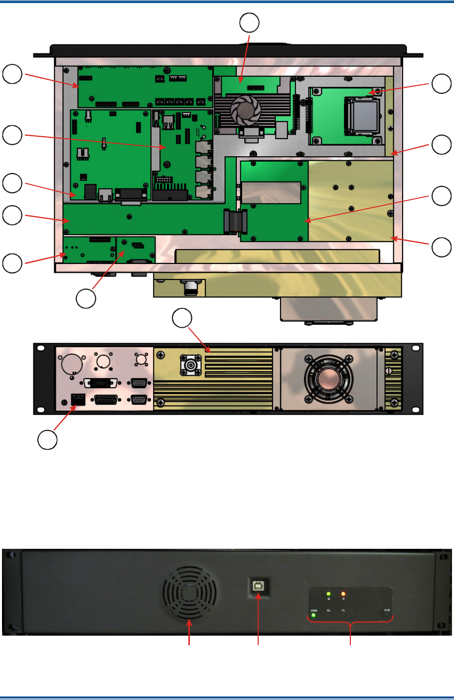
In Figure 1, the main modules and Printed Circuit Boards (PCBs) are numbered and refer to the
following:
1. Rx Module. 8. Rear Panel Ethernet PCB.
2. Exciter Module. 9. Power Distribution and LED PCB.
3. T36 Option – Tx Reference Oscillator. 10. Environment PCB.
4. Micro Controller PCB. 11. Management PCB.
5. Network Interface PCB. 12. Switch PCB.
6. Compact Flash Adapter PCB. 13. Power Amplifier.
7. Pico ITX Motherboard.
SGD-SB2025NT-TUM, Part 1
Jan 12 Page 21 GENERAL DESCRIPTION
Figure 1. SB2025NT Top and Rear Views.
4.1.1 Front Panel
The SB2025NT front panel is illustrated below in Figure 2. Custom versions of the front panel can
be supplied to Original Equipment Manufacturer (OEM) customers.
Figure 2. SB2025NT Front Panel.
1
2
3
4
5
6
7
8
9
10
11
12
13
LED Indicators
USB
Connector
Fan grill

SGD-SB2025NT-TUM, Part 1
Jan 12 Page 22 GENERAL DESCRIPTION
4.1.1.1 LED Indicators
The functions of the front panel LEDs are explained in Table 6 below. Each LED indicates the
status of the SB2025NT in real time.
Table 6. SB2025NT LED Functions.
LED FUNCTION
PWR Indicates the power supply voltage is within software selectable limits.
Rx The Rx is receiving a signal or the receiver’s squelch is open.
Tx The Tx is transmitting RF power.
ALARM A pre-arranged alarm condition exists.
M This is a tri-colour status LED that indicates the condition of the TM module if
fitted. The conditions that can be indicated are detailed in Table 7 below.
N This is a tri-colour status LED that indicates the condition of the NI module. The
conditions that can be indicated are detailed in Table 8 below.
4.1.1.2 Traffic Manager LED Indicator
The conditions indicated by the state and colour of the tri-colour status LED for a TM Module are
listed below in Table 7.
Table 7. TM Status Indicator.
Colour State Condition
Green Steady Normal Operation
Yellow Flashing (approx 1 Hz) Power ON and booting, for about 40 s from Power ON.
Green Flashing (approx 1 Hz) Traffic Manager firmware starting (about 40 s after a Power
ON or immediately after a firmware change)
Red Steady Unacknowledged system alarm
Yellow Steady Acknowledged system alarm still present
4.1.1.3 Network Interface LED Indicator
When power is first applied to the NI, the LED will not show the valid status of the module for
several seconds. The unit becomes operational in under 5 seconds, although it will take longer for
the Phase Locked Loop (PLL) to become locked when absolute synchronisation is achieved
assuming that the 1PPS timing signal is present at Power ON. If a GPS Rx is being powered by
the Solar unit, the GPS acquisition time will need to be included.
The conditions indicated by the state and colour of the tri-colour LED for a NI Module are listed
overleaf in Table 8.
SGD-SB2025NT-TUM, Part 1
Jan 12 Page 23 GENERAL DESCRIPTION
Table 8. NI Status Indicator.
Colour State Condition Precedence
Green Steady Normal Operation – Idle 5
Central NI = Voted Signal is present
Yellow Flashing (approx 0.5 Hz) Station NI = Rx Signal/squelch active 4
Central NI = Tx Key I/P is present
Yellow Steady Station NI = Tx Keyed 3
Red Flashing (approx 0.5 Hz) Loss of 1PPS signal or an inhibit condition
is applied 2
Red Steady No Network Communications 1
The precedence column shows what indication will be displayed when two or more states coincide;
the highest level is 1, the lowest level is 5.
4.1.1.4 USB Connector
The Universal Serial Bus (USB) Type B connector is used for basic connection of the ET.
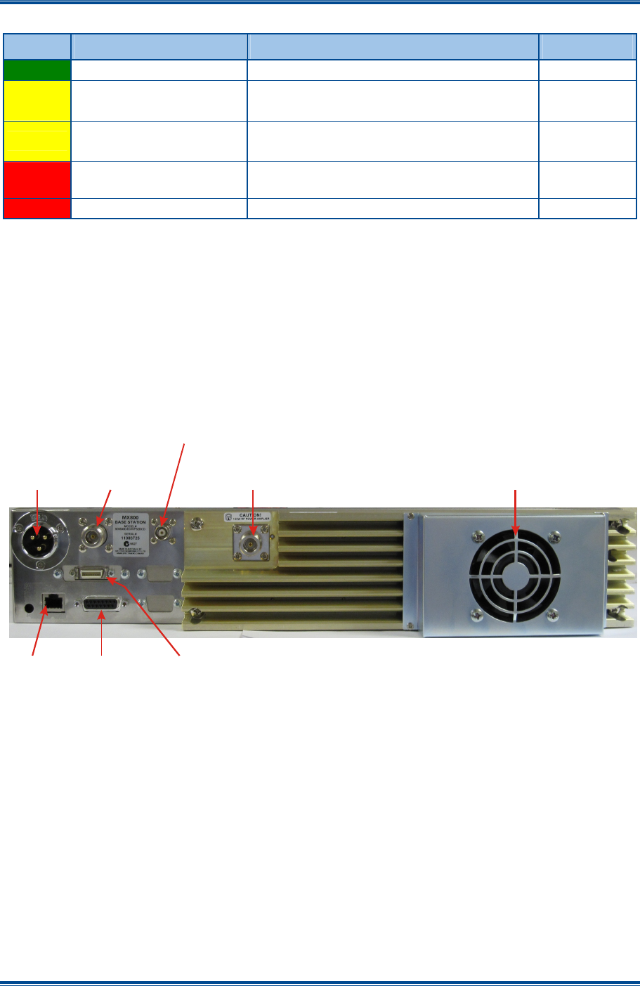
4.1.2 Rear Panel
The rear panel of the SB2025 series base station is identical for all models and is illustrated below
in Figure 3. The functions of each connector on the rear panel are detailed overleaf in Table 9.
Figure 3. SB2025NT Rear Panel.
DC Power
Input
CN8 N-Type
Tx Output
CN9
RJ45
CN7 BNC 10 MHz
High Stab. Osc. Input
CN1
GPS 1PPS
Timing Signal
CN3 I/O
Environment
Thermally
Controlled Fan
CN6 N-Type
Rx Input

SGD-SB2025NT-TUM, Part 1
Jan 12 Page 24 GENERAL DESCRIPTION
Table 9. Rear Panel Connections.
Connector #
Conn Type
Function Description
CN5 3 PIN DC Power I/P 13.8 V DC power I/P. Also +28 V I/P on spare
pin if required.
CN6 N TYPE N type Rx I/P N-Type connector can used for the I/P to the
Rx for full duplex operation.
CN7 BNC Rx I/P Standard BNC connector for the 10 MHz High
Stability Oscillator I/P.
CN8 N TYPE Tx O/P The RF power O/P from the Tx for full duplex
operation.
CN9 RJ45 Ethernet 10/100 base-T RJ45 Ethernet connector.
CN3 20-way
MDR-F Environment I/O Provided for monitoring and control of external
devices. Has 16 configurable I/Os.
CN1 DB15-F GPS 1PPS Timing
Provides the GPS interface, if required.
4.1.2.1 GPS (1PPS Timing Signal Input)
The 1PPS input can be accepted in either RS422 or TTL voltage format; the connections made to
this connector must match the input type and be correctly identified in the configuration
parameters. GPS National Marine Electronics Association (NMEA) data such as presented by the
Dalman GPS Rx 40762 will be displayed on the GPS page of the ET, however, this data input can
only be accepted in RS422 format.
4.1.2.2 Environment I/O
Integral to Solar is the provision for monitoring and control of external devices. All signals are
relative to ground and have voltage input and current switching limits. A low current 12 V supply is
also available from this connector to drive switching circuits (see Section 4.2 – Environment I/O
Overview).
4.1.2.3 DC Power Input
DC power is connected to the base station via this three pin male connector. For 50 W
transceivers, pins 2 and 3 are used for the 12 V DC pin 1 is unused. The DC input is fully isolated
from chassis and the equipment supply rails, making this option suitable for any supply earth
arrangement.
4.1.2.4 Transmitter Output
The Tx antenna connection on the SB2025 base stations is provided with a 50 Ω female N-type
socket.
The antenna cable connections must be made with 50 Ω N-types on flexible tails. The Voltage
Standing Wave Ratio (VSWR) of these connections should be tested prior to use by using of a
suitable test set, e.g. an Anritsu/Wiltron S331A. A good VSWR of 1.5:1 or better at the relevant Tx
and Rx frequencies should be ensured.
Mating connectors should be galvanically compatible with nickel outer and gold centre pin to
minimise passive intermodulation.
A minimum of 85 dB transmit-receive isolation should be provided by the antenna system and
associated filters.
It is recommended that a good quality flexible co-axial cable is used, e.g. with double-screening
braid and multi-strand copper inner.

SGD-SB2025NT-TUM, Part 1
Jan 12 Page 25 GENERAL DESCRIPTION
CAUTION
The Antenna System must to be protected against lightning by means of an
earthing system and surge protection device.
Do not connect Antenna Lightning conductors to the base station or Mains
Earth.
4.1.2.5 Receiver Input
This is a 50 Ω female N-type socket, which is used for the RF Rx input in duplex operation.
4.1.2.6 High Stability Oscillator Input (BNC)
This is a Bayonet Neill-Concelman (BNC) connector used as the 10 MHz high stability input.
4.1.2.7 Ethernet
The Ethernet socket is a 10/100 base-T RJ45 connection. The Ethernet socket provides a 10Base
Ethernet connection for the NI module and/or the TM module. If only the NI module is fitted, the
connection speed will be 10 Mbps, half duplex. If the TM module is fitted, the connection speed
will be 10/100Mbps as negotiated with the host Ethernet network.
4.1.3 Connector Pin-outs
4.1.3.1 Environment I/O
The connector pin-outs for the 20-way Mini Data Ribbon (MDR) Environment I/O socket are shown
below in Table 10.
Table 10. 20-way MDR Socket – Environment I/O.
Pin Function Pin Function
1 Input/Output # 1 11 Input/Output # 9
2 Input/Output # 2 12 Input/Output # 10
3 Input/Output # 3 13 Input/Output # 11
4 Input/Output # 4 14 Input/Output # 12
5 Input/Output # 5 15 Input/Output # 13
6 Input/Output # 6 16 Input/Output # 14
7 Input/Output # 7 17 Input/Output # 15
8 Input/Output # 8 18 Input/Output # 16
9 0 V – Common/Ground 19 0 V – Common/Ground
10 +12 V supply (max 300 mA) 20 +12 V supply (max 300 mA)
4.1.3.2 GPS (1PPS Timing Signal Input)
The connector pin-outs for the 15-way D GPS/1PPS Timing Signal socket are shown overleaf in
Table 11.
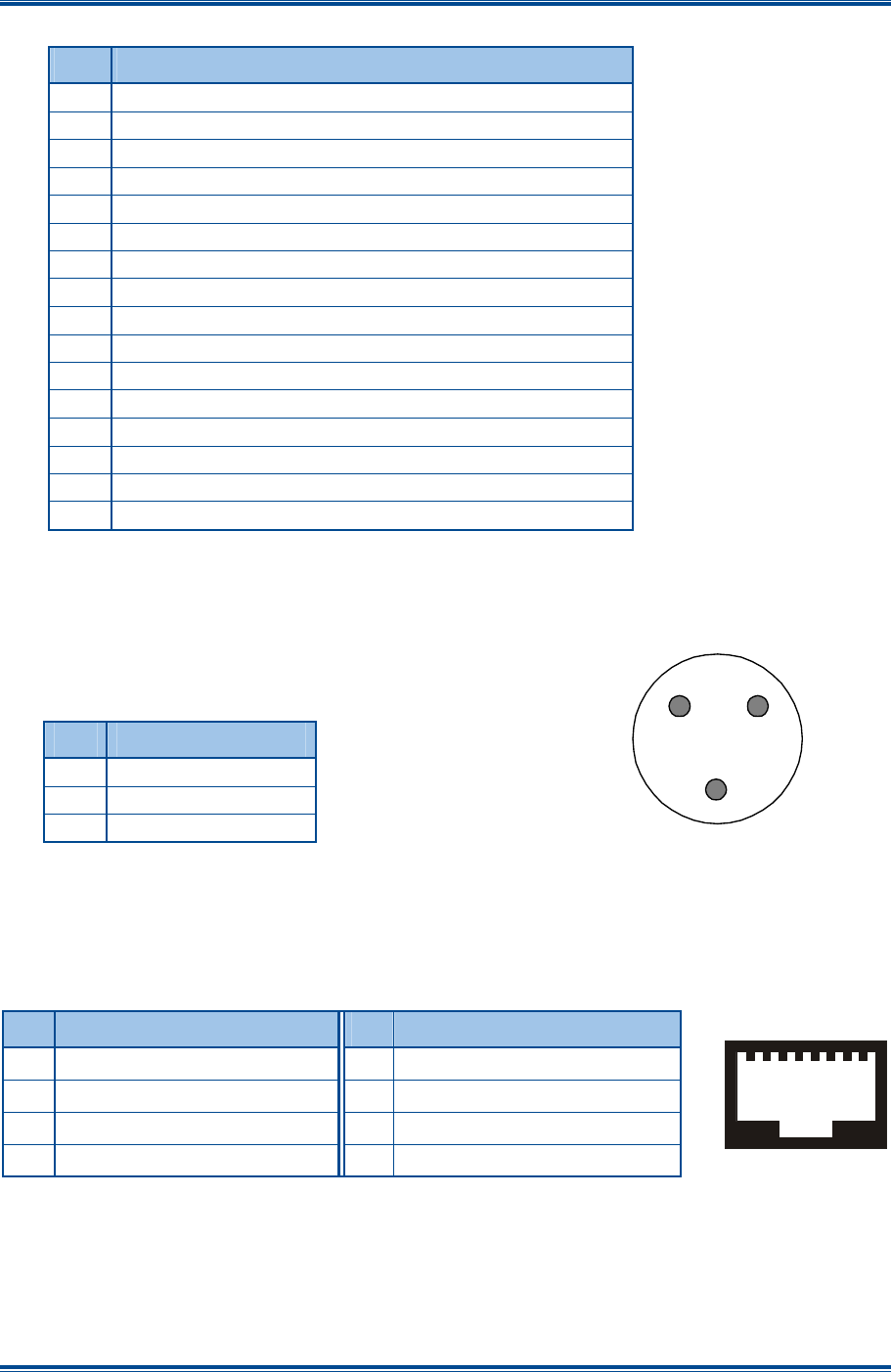
SGD-SB2025NT-TUM, Part 1
Jan 12 Page 26 GENERAL DESCRIPTION
Table 11. 15-way D Socket – GPS/1PPS Timing Signal.
Pin Function
1 +12 V supply (reverse feed & current limited protection)
2 GPS Data I/P – RS422 ‘A’
3 GPS Data I/P – RS422 ‘B’
4 1PPS Signal I/P – RS422 ‘A’
5 1PPS Signal I/P – RS422 ‘B’
6 Not Connected (NC)
7 NC
8 NC
9 NC
10 Data to GPS Rx – RS422 ‘A’ (not normally used)
11 Data to GPS Rx – RS422 ‘B’ (not normally used)
12 0 V – Common/Ground
13 NC
14 1PPS Signal TTL Input – reference to 0 V
15 NC
Shell
Cable screen
4.1.3.3 DC Power Input
DC – 3-pin male connector: only two pins are wired to suit the
voltage range.
Table 12. DC Power Connector.
Pin Function
1 Unused
2 Ground
3 +13.8 VDC
4.1.3.4 Ethernet
The standard network cable wiring for an RJ45 is shown below in Table 13.
Table 13. RJ45 – Standard Network wiring.
Pin
Description Pin
Description
1 Tx Data+, balanced I/P 1 5 NC
2 Tx Data−, balanced I/P 2 6 Rx Data−, balanced O/P 2
3 Rx Data+, balanced O/P 1 7 NC
4 NC 8 NC
1
8
3
1
2
+ -

SGD-SB2025NT-TUM, Part 1
Jan 12 Page 27 GENERAL DESCRIPTION
4.2 E
NVIRONMENT
I/O
O
VERVIEW
The Environment I/O interface module in Solar provides a facility to monitor and control external
devices in a simple “ON/OFF” or “Active/Inactive” state. This information is conveyed via the data
packet protocol such that a change in input status and output change command will be notified,
typically within 1 second.
There are sixteen connection points; each point can be designated as an input or an output to suit
the needs of the equipment environment. The input conditions are signalled back to the TM for
display or notification, which is also the point of operation of the control outputs. Monitoring of
inputs and operation of outputs may also be conducted locally.
Their purpose may be a mixture of anything the user finds useful – e.g. radio base station alarms,
monitoring the building state, control equipment switching, etc.
4.2.1 Inputs and Outputs
The I/Os are in binary form, i.e. On/Off, High/Low etc. Setting the “polarity” of the inputs (monitor
points) is important if they are to be used as Alarm triggers. Each port can be “named” to assist in
identification of the function connected to it; these names are entered into the unit via the ET. The
names are passed down to the TM as part of the Supervision Data link.
Connection to these I/O ports is not intended to be ‘universal’ and, therefore, requires some
thought in order to achieve the required functionality. Particularly, the external wiring of the Inputs
(Monitor Points) needs to be addressed with some care both from the electrical as well as the
functional point of view.
Bear in mind the effect on the function if the plug connecting the Environment is disconnected. If
the function has been wired to be open circuit in its normal state and closed circuit to show an
alarm or error, then, with the connector removed, the alarm state can never be detected. Perhaps
it would be an advantage to wire the other way round, then an alarm is detected – even if it is only
to show the connector has been removed.
4.2.2 Input ‘Polarity’
In order to assist with the detection of an “error” state or at least to get the status indicators to work
in a logical sense, a method of inverting the “polarity” of the sense is provided via the ET. If a
spare input is available, it may be useful to link this to ground within the mating connector and,
therefore, reflect the state of the connector being present or not.
4.2.3 Output ‘Polarity’
The “CONDITION ON” state for each input may be defined as input low or input high as
appropriate on an individual input basis. Similarly, the “ON” state for each output may be defined
as “Button IN” or “Button OUT” on an individual output by output basis to suit the required purpose.
4.2.4 Electrical Constraints
The source of an input signal may be in the form of dry switch contacts, open collector, or ‘Hi/Lo’
voltages where a “Hi” voltage is ≥1.3 V and <50 V, and a “Lo” voltage is ≤1.0 V. An open circuit
will ‘float’ up to approximately 3 V as a 3.3 kΩ pull-up resistor is used and, therefore, an external
input must present less than a 2 kΩ resistance to be registered as a low state.
The outputs are high current open-collector Darlington arrays and can be used on loads supplied
externally to a maximum voltage of 50 V and switch a maximum current of 350 mA. At this current,
the ‘ON’ output voltage will be approximately 1 V.

SGD-SB2025NT-TUM, Part 1
Jan 12 Page 28 GENERAL DESCRIPTION
The environment I/O is arranged into two groups where each group connects to the same physical
device (integrated circuit). To keep the power dissipation of each device within operating limits, the
total current that may be switched by all the control outputs in one group must not exceed 500 mA
when all outputs are “ON”.
4.3 M
ODULE
F
UNCTIONAL
D
ESCRIPTION
4.3.1 Exciter Module
The Exciter module generates the low level, on frequency, RF Tx signal that is later amplified to
nominal output power level by the PA module. The Exciter consists of a VCO and associated main
RF board, which, in conjunction with the reference oscillator and the PLL circuitry, forms a two-
point modulation programmable frequency synthesiser. Frequency programming data is received
from the Micro Controller via a 3-wire serial data bus.
The Exciter module features a modulation bandwidth from DC with an ultra wide RF bandwidth of
20 MHz to 1000 MHz at an average RF output power of 300 mW. To change from one band to
another, all that is required is to change the plug-in VCO board and reprogram the radio. No other
manual adjustment or change is required.
Should a high stability reference be required, the exciter can be fitted with a connector for an
external reference oscillator input.
The fractional N synthesiser provides ultra low spurii while still maintaining fast lock times even at
6.25 kHz step size.
An optional built-in turn around mixer provides advanced diagnostics such as Rx sensitivity tests.
4.3.2 Receiver Module
The Rx module accepts the low level RF input signal and amplifies, filters and conditions the signal
prior to detecting the wanted audio component. The Rx module features the same advanced
synthesiser and wide bandwidth as the Exciter. Only the front-end bandpass filter and VCO need
to be changed in order to support different frequency bands, resulting in significant flexibility and
end-user cost savings. The purpose built front-end bandpass filter has a wide no-adjust bandwidth
equal to the band allocation (refer to Appendix A for details of the band allocations).
The Rx has high sensitivity while maintaining excellent intermodulation immunity and adjacent
channel rejection. A dual first Intermediate Frequency (IF) filter provides excellent rejection to
common known spurious responses. High blocking of over 100 dB typical ensures that strong
interfering signals do not desensitise the Rx when receiving weak signals.
4.3.3 Power Amplifier Module
RF from the Exciter passes via a coaxial cable to the input of the PA Module and is first attenuated
by a 50 Ω pad, which is used to provide a good 50 Ω source impedance for the first Laterally
Diffused Metal Oxide Semiconductor (LDMOS) driver amplifier. The RF is amplified to around
5 Watts at the driver output, and is band dependant. (Note. This point does not have 50 Ω
impedance and the drive power cannot be measured directly with a 50 Ω Wattmeter). The signal
from the driver is then matched by a broadband network to drive the low input impedance
associated with the final transmit LDMOS PA transistor. The transistor’s low drain impedance is
then also matched back to 50 Ω by a broadband matching network covering a very wide
bandwidth. Prior to transmission, a low loss 13 element elliptical low pass filter, filters out the
unwanted harmonics to less than –90 dBc.
A dual directional coupler consists of coupled microstrip transmission lines fabricated on the PCB
artwork. The sampled RF energy is rectified to provide a proportional DC voltage output.

SGD-SB2025NT-TUM, Part 1
Jan 12 Page 29 GENERAL DESCRIPTION
The Press (Push) To Talk (PTT) signal enables the amplifier circuit by providing bias to the
transistors. A thermistor TS1, physically located on the PA heatsink monitors the heatsink’s
temperature and is monitored by the Micro Controller.
The PA is very compact and efficient for high reliability and low cost. The heatsink has minimal
temperature rise even under continuous operation, ensuring the best Mean Time Between Failure
(MTBF) obtainable for a practical design.
4.3.4 Micro Controller Board
The Micro Controller Board is physically located behind the rear panel connectors and all signal
connections (apart from the RF connections) external to the transceiver are made via the controller
card. User settable jumpers and DIP switches are located on the card as are level adjustment
potentiometers.
The Micro Controller controls the operation of the RF modules and acts as the interface between
the Solar NI, indicators and the RF modules. It also processes transmit and received audio to and
from the Exciter and Rx modules.
The circuit board has an onboard Electrically Erasable Read-Only Memory (EEROM), which stores
all of the user channel related data such as frequencies. A serial port at the front of the SB2025
provides access to the NI and Controller card and, in conjunction with the Simoco ‘Engineering
Terminal’ and ‘MxTools’ programming utilities, allows the user fully configure the SB2025 base
stations.
Digipots under the control of the processor ensure that user set up levels for Tx deviation and
power levels are correctly set for each channel.
4.3.5 Network Interface
The Network Interface is physically located on a sub-chassis mounted above the Micro Controller
Board. Signal connections are made to the Micro Controller Board for audio, Tx/Rx control and a
serial data link for configuration of the Micro Controller. Other connections are made via Molex
and RJ45 connectors for serial data, 1PPS timing/NMEA data and Ethernet. On receive, the
Network Interface samples the Rx demodulator output at 24 kHz and processes the data before
sending it to the TM. On an analogue call, the Digital Signals Processor (DSP) carries out
CTCSS/Continuous Digital Coded Squelch System (CDCSS) decoding and g.726 encoding of the
received audio. The micro controller adds additional information such as RSSI and any detected
sub-audio tone/code before packaging and sending to the TM. On a P25 call the DSP provides
Continuous 4 Level Frequency Modulation (C4FM) demodulation.
On transmit, the NI receives Ethernet packets from the TM and generates appropriate analogue or
P25 signals for passing to the wideband modulation input of the Exciter via the Micro Controller
Board. CTCSS/CDCSS is generated in the correct phase and mixed with the analogue audio.
A PLL is maintained locked to the 1PPS timing reference and along with time stamps in the
Ethernet packets ensures transmitted audio/P25 data is correctly in phase for simulcast
transmission.
4.3.6 ITX
The ITX (also known as Single Board Computer (SBC)) uses the Linux operating system and runs
the TM application.
4.3.7 Compact Flash
Contains the operating system, the TM application and its configuration files.

SGD-SB2025NT-TUM, Part 1
Jan 12 Page 30 GENERAL DESCRIPTION
4.3.8 SBC Support PCB
This PCB includes a 5-port Ethernet switch, two USB sockets, physical support for the Pico Power
Supply Unit (PSU), USB Universal Asynchronous Receiver/Transmitter (UART) and RS232
interfaces for the ITX.
4.3.9 Aux PCB
This PCB contains a micro controller that monitors the operation of the ITX and will attempt to
reboot it if necessary. Also included are LEDs and drivers, DC distribution for other PCBs,
Environment I/O, GPS interface and a 4-port USB UART for connection to the PC Engineering
Terminal Application.
4.3.10 Pico PSU
The Pico PSU takes the 12 V DC supply and provides all the voltage rails needed by the ITX and
supporting PCBs.

SGD-SB2025NT-TUM, Part 1
Jan 12 Page 31 TECHNICAL DESCRIPTION
5 TECHNICAL DESCRIPTION
The internal design of the SB2025NT is of a modular nature allowing for simple configuration and
maintenance while ensuring minimal downtime. For reference purposes, the block diagram of the
SB2025NT is shown in Figure 4.
5.1 E
XCITER
M
ODULE
RF from the VCO on SKU-1 at a nominal level of +3 dBm is applied to the fractional-N synthesiser
IC10 main divider input. This signal is compared with the reference oscillator frequency and the
correction voltage from the synthesiser’s charge pump output is filtered then amplified by the non-
inverting low noise operational amplifier IC9A. This correction voltage is fed back to the VCO to
maintain loop lock, as well as being fed to the Micro Controller via SKD-14. A lock detect signal
from IC10 is also fed to the Micro Controller via SKD-16. The operational amplifier uses a 25 V
power supply (generated on the Micro Controller) in order to provide a wide tuning range voltage to
the frequency control varicaps located on the VCO board. Frequency programming data for the
Exciter is sent to the synthesiser chip from the Micro Controller via a serial data line on SKD-18
under the control of the Clock (SKD-15) and Strobe (SKD-17) lines.
Provision is made for the optional injection of an external reference frequency. If this option is
selected, CN3 is fitted and X1 is not fitted. Components R30 and TR7 are also omitted.
A second RF output from the VCO on SKT-6 also at +3 dBm is used as the main transmit RF
amplifier signal source. This main signal is first buffered by a very high isolation circuit consisting
of a 10 dB pad and a Monolithic Microwave Integrated Circuit (MMIC) amplifier (IC1). The signal is
further amplified by IC2 and a variable gain wide band amplifier with 40 dB control range and
power output of 300 mW. The drive power of this stage is used to set the output power to the main
PA under the control of the DC voltage on SKD-4 from the Micro Controller board.
The VCO boards and synthesiser circuits are the same for the Exciter and Rx modules. The VCO
consists of a 10 mm ceramic coaxial resonator with common base oscillator for low phase noise for
bands 805 MHz - 960 MHz. Frequencies below 520 MHz use a LC tank circuit. The power supply
to the VCO consists of an 8 V regulator and active filter for maximum noise rejection. It is
controlled by the Micro Controller through SKD-7, which connects to switch TR6. For standard
modulation, transmit audio is fed on SKD-8 to the conventional point of the VCO varactor. For two
point modulation, audio is also fed via SKD-19 to the voltage control pin of the VC-TXCO, this in
effect cancels out the PLL error that would otherwise have occurred for low audio frequencies,
therefore, resulting in a flat VF response.
5.2 R
ECEIVER
M
ODULE
The Rx signal from the antenna enters on CN1 a three section bandpass filter, which provides the
initial filtering for the front-end amplifier. The front-end amplifier IC12 is a broadband high
performance MMIC with a gain of 18 dB, noise figure of 3 dB and third order intermodulation
intercept of +36 dB. A 4 dB pad and a second three section bandpass filter follow this, and a high
level double balanced mixer M1.
The Rx uses high side local oscillator injection for bands A to M and low side injection for all other
bands. RF from the VCO main output on SKT-6 is buffered and amplified to +17 dBm by IC4 and
injected in the high level mixer, which down converts the signal to the first IF frequency of 90 MHz
(45 MHz for bands A and B, and 70 MHz for bands A4). This IF signal from the mixer is terminated
by a bi-directional constant impedance network and is then amplified by a bipolar amplifier TR2
with a gain of 15 dB and third order intermodulation intercept of +35 dB. This provides a high
degree of intermodulation rejection for the Rx. A 4-pole crystal filter FL3A/B with its associated
matching networks follows this stage. The signal is further amplified and filtered by a transistor
amplifier TR3 and its associated 2-pole crystal filter FL4 before being fed into the main IF
demodulator chip IC1 with a second IF frequency of 455 kHz. The resulting audio is passed out to

SGD-SB2025NT-TUM, Part 1
Jan 12 Page 32 TECHNICAL DESCRIPTION
the Micro Controller board on SKD-3. The RSSI from IC1 is buffered by IC5A and connected to
the Micro Controller board via SKD-4.
RF from the VCO on SKU-1 at a nominal level of +3 dBm is applied to the fractional-N synthesiser
(IC10) main divider input. This signal is compared with the reference oscillator frequency and the
correction voltage from the synthesiser’s charge pump output is filtered then amplified by the non-
inverting low noise operational amplifier (IC11A). This correction voltage is fed back to the VCO to
maintain loop lock as well as being fed to the Micro Controller via SKD-14. A lock detect signal
from IC10 is also fed to the Micro Controller via SKD-16. The operational amplifier uses a 25 V
power supply (generated on the Micro Controller) in order to provide a wide tuning range voltage to
the frequency control varicaps located on the VCO board. Frequency programming data for the Rx
is sent to the synthesiser chip from the Micro Controller via the a serial data line on SKD-18 under
the control of the Clock (SKD-15) and Strobe (SKD-17) lines
The Micro Controller, through an enable signal on SKD-8, controls the local oscillator signal to the
mixer. This signal switches the supply to the local oscillator amplifier and is used to enable or
disable the Rx.
Provision is made for the optional injection of an external reference frequency. If this option is
selected, CN3 is fitted.
5.3 P
OWER
A
MPLIFIER
M
ODULE
The SB2025NT now supports Simoco’s new full switching bandwidth PA Module (Wide Band PA),
which requires no tuning, equals, exceeds or covers several of Simoco’s band allocations, (refer to
Appendix A for details of the band allocations). This new generation PA features much wider RF
bandwidth, higher efficiency, greater stability out of band and to zero power levels.
This PA is now being rolled out as the standard production PA.
5.3.1 Wide Band PA (50 Watt Model)
RF from the Exciter passes via a coaxial cable to the input of the PA Module and is first attenuated
by a 50 Ω pad, which is used to provide a good 50 Ω source impedance for the first LDMOS driver
amplifier. The RF is amplified to around 5 W at the driver output, and is band dependant. (Note.
This point does not have 50 Ω impedance and the drive power cannot be measured directly with a
50 Ω Wattmeter). The signal from the driver is then matched by a broadband network to drive the
low input impedance associated with the final transmit LDMOS PA transistor. The transistor’s low
drain impedance is then also matched back to 50 Ω by a broadband matching network covering a
very wide bandwidth. Prior to transmission, a low loss 13 element elliptical low pass filter, filters
out the unwanted harmonics to less than –90 dBc.
A dual directional coupler consists of coupled microstrip transmission lines fabricated on the PCB
artwork. The sampled RF energy is rectified to provide a proportional DC voltage output.
The PTT signal enables the amplifier circuit by providing bias to the transistors. A thermistor, TS1,
physically located on the PA heatsink, monitors the heatsink’s temperature and is monitored by the
Micro Controller.
5.3.2 Wide Band PA (100 Watt Model)
The 100 W models are base on the 50 W technology, using two LDMOS final PA transistors to
achieve a 100 W RF output power rating. The final transistor’s low drain impedance is then also
matched back to 50 Ω by a broadband matching network covering a very wide bandwidth. Prior to
transmission, a low loss 13 element elliptical low pass filter, filters out the unwanted harmonics to
less than –90 dBc.

SGD-SB2025NT-TUM, Part 1
Jan 12 Page 33 TECHNICAL DESCRIPTION
Table 14. 100 W PA Banding Information.
100 W Wide Band PA
Model
Frequency Coverage
A3V 39 MHz – 47 MHz
ABV 66 MHz – 88 MHz
CDV 135 MHz – 175 MHz
FV 217 MHz – 222 MHz
NWV 400 MHz – 435 MHz
OWV 435 MHz – 470 MHz
PWV 450 MHz – 495 MHz
5.4 M
ICRO
C
ONTROLLER
B
OARD
The SB2025 Micro Controller Board has four main functions:
• Overall radio management.
• Tx and Rx signal processing.
• RF power control.
• User interface.
5.4.1 Overall Radio Management
In addition to analogue signal processing circuitry, the Micro Controller board accommodates an
80C552 microprocessor IC1, a 64 kb Erasable Programmable Read-Only Memory (EPROM) IC3,
32 kb Random Access Memory (RAM) IC4, a 16 kb Electrically Erasable Programmable Read
Only Memory (EEPROM), as well as address decoding, I/O latches and other miscellaneous
circuitry. The Micro Controller is responsible for ensuring that the radio acts as programmed by the
user. It stores the user-entered parameters for each channel in the EEPROM. This information
includes Rx and Tx RF frequencies; Rx and Tx CTCSS frequencies, as well as RF output power
and operating mode. An eight channel analogue to digital converter allows the microprocessor to
read eight analogue values internal to the radio, which, in conjunction with the digital inputs to the
microprocessor, allow the operating status of the radio to be monitored and controlled.
The analogue items that are read are listed below in Table 15.
Table 15. Microprocessor Port Parameters.
Port Parameter
ADC0 Received Signal Strength Indication (RSSI)
ADC1 Detected Discriminator Output Level
ADC2 DC Operating Voltage
ADC3 Rx VCO Tuning Voltage
ADC4 Tx VCO Tuning Voltage
ADC5 PA Temperature
ADC6 PA Forward Power
ADC7 PA Reflected Power

SGD-SB2025NT-TUM, Part 1
Jan 12 Page 34 TECHNICAL DESCRIPTION
The Micro Controller sends programming data to the synthesiser ICs on the Rx and Exciter
modules each time the channel is changed as well as on PTT. This information is communicated
to the Rx and Exciter modules by way of bussed data and clock lines on SKC/D-18 and SKC/D-15
(Exciter/Rx) and an individual module strobe on SKC/D-17. A lock detect signal from each module
on SKC/D-16 is read by the Micro Controller.
In addition to the synthesiser programming bus, an I
2
C bus goes to each of the modules. This bus
is currently unused.
5.4.2 Tx Signal Processing
Tx audio may be sourced from a number of different paths. These include VF from line, T/T audio,
the microphone, and DC FM/Wideband input, Tone generator from the Micro Controller, Test Tx
VF inject from the Monitor port, CTCSS generator and the internal RF modem.
The Tx VF path is readily user configurable with most major functional blocks being possible to
either select or bypass by means of links (refer to Table 4 – Micro Controller Jumpers for details
of link settings). The VF from line enters the board on SKH-14 and RV4 (Tx VF gain) provides gain
adjustment to accommodate different line levels. This is followed by a selectable compressor
(IC34A) with 30 dB dynamic range. The output of the compressor, apart from being fed to the
main Tx audio path, is also connected to the input side of the “Line” Fast Frequency Shift Keying
(FFSK) modem and via a gain control pot the speaker amplifier (IC60). Following the main Tx
audio path, IC36B serves to switch the VF further on the Tx audio path or, under the control of the
external input on SKH-13, to loop it back to the line output via RV7, which provides level
adjustment for the looped back signal. From this switch, the VF passes though a second switch
IC32B under the control of the Micro Controller and the external Tx talk line on SKH-10. This
switch is used to disable the line Tx VF path. From here the VF passes through a pre-emphasis
stage C66, R67 and a 300 Hz high pass filter (IC30B and IC29A) each of which is selectable
through links. The output of this filter is fed to IC30A a summer/limiter amplifier.
The summing point of this amplifier also serves to combine the audio from the T/T path, which is
level adjusted by RV3, the microphone which is processed through a similar compression, pre-
emphasis and filtering chain as the line VF, the tone (Morse code) signal from the microprocessor,
the DC FM input, which enters the board on SKH-6 and the Test Tx VF injection from SKE-2. The
latter three inputs are all at fixed levels. RV2 on IC30A provides overall gain adjustment.
Following the limiter amplifier is the Tx VF low pass filter. The standard Bessel filter has a 3.4 kHz
cut off frequency. A second summing amplifier IC24B follows, which combines the CTCSS,
optional modem (IC52 and IC54) and Wideband audio inputs with the Tx VF. Level adjustment of
the CTCSS signal is in three 0.85 dB steps either above or below the nominal level (10% of max
dev). These level steps are setup using the Configure screen of MxTools. The output of this final
stage is fed to two microprocessor-controlled digipots, which serve to adjust the modulating signal
level to the VCO and the reference oscillator. A third digipot is used to provide an offset null for the
reference oscillator centre frequency. Adjustment of these levels is also by way of MxTools using
the Channel Edit screen.
5.4.3 Rx Signal Processing
In a similar fashion to the Tx audio path, the major functional elements of the Rx audio path are
capable of being selected or bypassed by means of links.
Discriminator audio enters the board on SKD-3 and is fed to a selectable 300 Hz high pass filter
comprising IC37 and IC38B. This output or an unfiltered version of the discriminator audio is fed
via a switch IC32A to the TTR (repeater) path. The switch is used to disable talk through audio
under the control of the microprocessor and the external Tx talk line on SKH-10. Following the
high pass filter, a selectable 3.4 kHz cut-off low pass filter IC38A and IC39B connects to the de-
emphasis circuit IC39A. From here the audio passes through the mute switch IC32C that is under
control of the microprocessor and on to the Rx talk switch IC36C, which is controlled externally
from SKH-3. This second switch is used to disable Rx audio to line. A final switch IC36A selects

SGD-SB2025NT-TUM, Part 1
Jan 12 Page 35 TECHNICAL DESCRIPTION
between Rx audio and Tx looped back audio for output to line via amplifiers IC40A and IC40B.
Secondary inputs to these amplifiers are the Tx audio from the line modem and microphone audio
to line. The output on SKH-2 forms an unbalanced 600 Ω VF output to line and, alternatively,
outputs SKH-2 and SKH-11 form a differential output.
Discriminator audio is also fed via a low pass filter IC31 to the CTCSS decoder as well as to a level
detector D9 the output of which is connected to ADC1 on the microprocessor.
Discriminator audio is also fed to the mute detection circuit. This comprises a high pass filter IC41
followed by RV6/6B, which sets the mute threshold. Following amplification by IC42A and
rectification by IC42B and IC43A, a comparator, IC43B, determines when the detected signal
passes a fixed threshold. The output of the comparator is fed to the microprocessor and via a
selectable inverter to SKH-4.
Discriminator audio is also fed to Rx port of the RF modem IC54.
5.4.4 RF Power Control
Forward power is controlled by the microprocessor through two mechanisms. Based on pre-
programmed per channel adjustments, the microprocessor sets the digipot IC10 to a reference
setting. IC23A serves as a comparator and, with the non-inverting input connected to the wiper of
the digipot, is set up with a reference voltage. The detected actual PA forward power is fed to the
inverting input of IC23A. The error voltage at the output of IC23A is fed to the exciter output power
control circuit via SKC-4 and the action of the control loop is to set the RF power such that the
actual detected volts equals the reference volts. The digipot setting is static for each channel
unless the required forward power is changed.
The voltage to the top of the digipot is set up by the microprocessor through the Pulse Width
Modulator (PWM) output PWM1. On PTT, the ON duty cycle of the PWM1 output is progressively
increased and the filtered result of this forms a ramp to the top of the power control digipot. Once
100% duty cycle is reached, full power is produced. This results in a fast but controlled RF power
rise characteristic.
5.4.5 User Interface
All user interfaces to the SB2025, except the RF connections, are made by way of the front panel
USB interface on the Aux PCB and then via an internal serial connection to the NI or ITX for the
ET. The MxTools application for radio configuration also uses this route to the NI but is passed on
over another serial connection to the Micro Controller Board.
Output latch IC18 drives the six LED indicators on the front panel. The function is described in
Section 4.1.1.
Input latch IC14 serves to accept the programmed status of the eight bit binary channel select DIP
switch SW1. Refer to Appendix B for programming instructions.
Input latch IC13 serves to accept the programmed status of the six bit binary mode select DIP
switch SW2. Refer to Section 3.2.2.2 for mode selection instructions.
IC22 provides CMOS to RS232 conversion for the serial port.
5.5 S
OLAR
T
RAFFIC
M
ANAGER
The TM is a software application running on the ITX board and manages all aspects of a channel
including NIs other than its physically associated one if necessary and a DFSI conforming to
TIA.102-BAHA.

SGD-SB2025NT-TUM, Part 1
Jan 12 Page 36 TECHNICAL DESCRIPTION
This application receives packets from one or more NIs every 20 ms, votes the best quality signal
and presents it to a dispatcher either via a DFSI connection or as an analogue 4-wire using an
additional stand-alone Network Interface.
Outgoing analogue or P25 audio/data from analogue dispatcher, DFSI or voted call is time-
stamped and sent to all associated NIs for transmission. If multiple NIs are connected they can be
synchronised to create a simulcast channel.
The TM application stores the complete configuration for the channel on its internal compact flash
memory card. All the configurable settings on all the connected NIs are stored here and are kept
synchronised with the NIs over a control channel that is multiplexed into the 20 ms Ethernet packet
structure.
A number of conditions are monitored throughout the channel and alarms can be raised if
necessary. These can be displayed and acknowledged by the ET or by SNMP using a third party
Network Management System (NMS) using the supplied Management Information Base (MIB).
5.6 S
OLAR
N
ETWORK
I
NTERFACE
The NI provides the connection between the Ethernet link and the radio base station hardware.
Traffic and control information is multiplexed into fixed length packets and sent to/from the TM
every 20 ms.
There are two CPUs in the NI. One, a PIC, manages the Ethernet interface, the control of the base
station (RSSI, PTT, alarms etc.), the PLL that is locked to the external 1PPS timing signal for
simulcast transmission, the serial ports for the ET and connection to the Micro Controller board,
and the handling of all the configuration data to/from the TM. The other, a DSP, manages all the
analogue signal processing including the C4FM modulation/demodulation, tone detection,
generation and synchronisation, deviation limiter, FM pre/de-emphasis, g.726 encoding/decoding
and in the case of a Central NI, AMBE +2 vocoding.
The Network Interface has two analogue ports. A duplex wide band unbalanced port connects
directly to the Rx’s discriminator output and the Tx’s wideband input. This has a flat frequency
response from virtually DC to over 3.2 kHz to enable P25 C4FM.
The other analogue port is duplex, 600R transformer coupled and is provided for when the NI is
used as an analogue dispatcher interface. This is not used in the SB2025.
There are two serial ports. One connects to the USB serial interface on the Aux PCB and allows
connection of the ET and MxTools applications. The other connects internally to the Micro
Controller PCB and passes information to control the operating condition of the base station,
channel, Tx power etc.
1PPS timing and optionally NMEA data is provided by the Aux PCB when a GPS Rx is connected
to the SB2025.
The 26 way Facilities connector carries the two analogue ports described above an analogue input
for an RSSI voltage from the receiver. Three relay change-over contacts and three opto-isolated
inputs are provided. One relay keys the Tx and two of the inputs are used for Rx mute indication
and alarm status. An RJ45 socket provides the 10BaseT Ethernet interface and is connected
internally to the Ethernet switch on the SBC Support PCB.
Power to the NI is 12 V DC and is supplied by the Aux PCB.
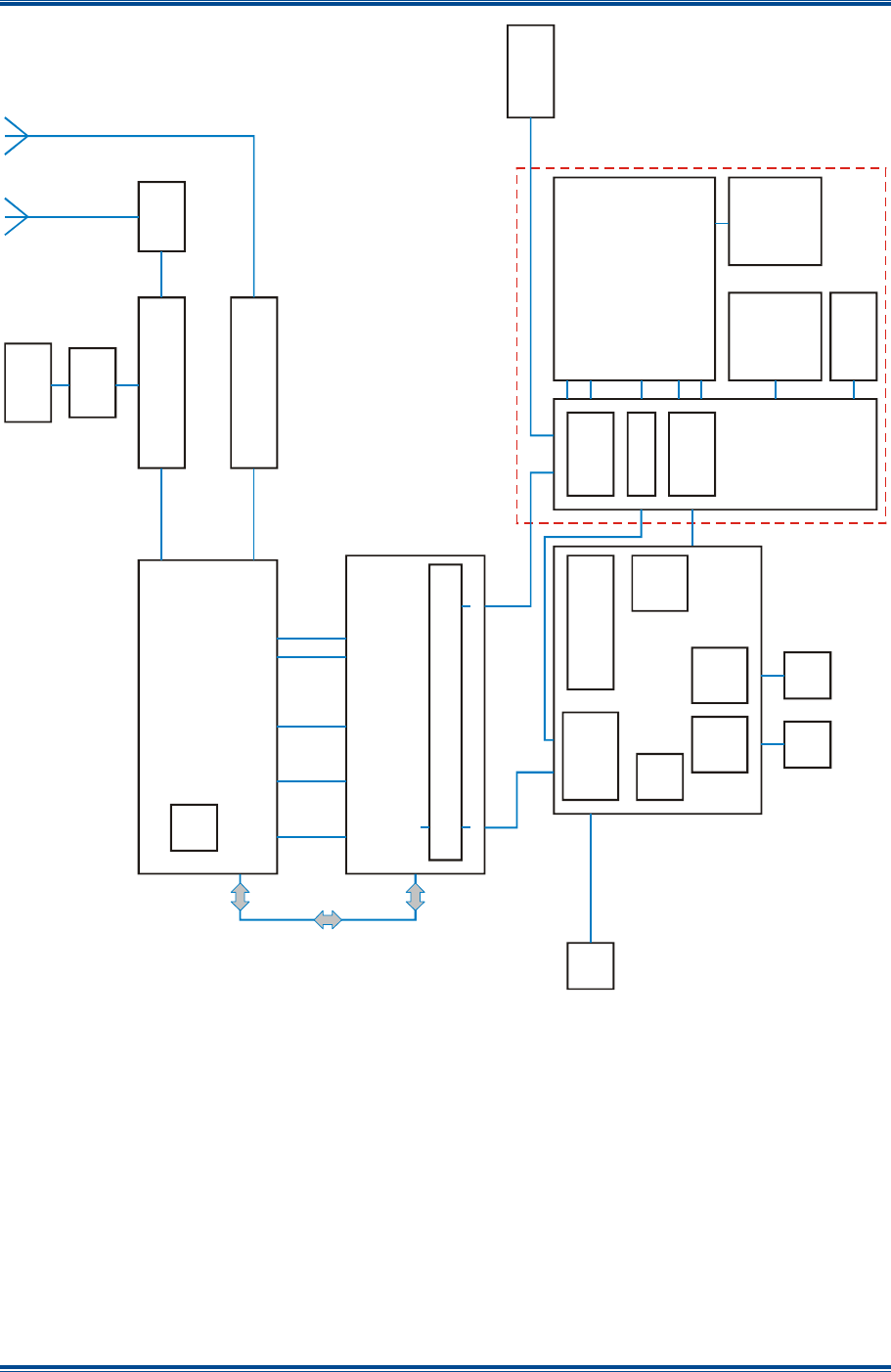
SGD-SB2025NT-TUM, Part 1
Jan 12 Page 37 TECHNICAL DESCRIPTION
Figure 4. SB2025NT Block Diagram.
6x
Status
LEDs
Serial
Power
ETH0
USB
Serial
Start/Reset
Buttons
Serial 1
Serial 2
Ethernet
Status
LEDs
Software serial bridge allowing MXTools and DFSI (Ethernet)
access to MX800 Controller functions
MDR
20-way
D-Skt
15-way
Env GPS
USB to
Serial
USB-B
Skt
Power Distribution
AUX
µProc
Ethernet
Switch
Serial to USB
Start/Reset &
Level shift
logic
Wide I/P
PicoPSU
USB Facilities
Dongle
C
o
m
p
a
c
t
F
l
a
s
h
&
A
d
a
p
t
e
r
P
C
B
P
i
c
o
I
T
X
S
B
C
SBC
Support
D1099-0010-G-01
Aux Support
D1099-0009-G-01
MX800 Controller
TX
RX
P
A
Hi-stab
Ref.
Hi-stab I/P
Connector
Network Interface
R
J
4
5
E
t
h
e
r
n
e
t
I
D
E
A
l
a
r
m
P
T
T
C
O
R
C
4
F
M

SGD-SB2025NT-TUM, Part 1
Jan 12 Page 38 ALIGNMENT & TESTING
6 ALIGNMENT AND TESTING
The SB2025NT test and alignment procedures are divided into two main sections. The first section
is a transceiver level procedure, which assumes that the radio is fitted with working modules. The
second section contains the individual module test procedures.
6.1 T
RANSCEIVER
S
ETUP
,
C
ALIBRATION AND
A
LIGNMENT
This section explains how to setup, calibrate and align the complete SB2025NT Base Station. A
number of procedures are required to fully initialise the SB2025NT. The following test equipment
will be needed:
• PC with MxTools and ET (SB2025 Base Station Programming Utilities).
• RF Test Set (HP 8920) or equivalent.
• Oscilloscope.
• RF Power Meter (Watts).
• RF Signal Generator.
• Multimeter.
• +13.8 V DC Power Supply
The order of some, but not all, of the procedures is important to ensure correct setup of the radio.
The order of the procedures as described is recommended and those that are critical are
mentioned. If the radio has been previously setup and the user intends to recalibrate and align the
radio then Sections 6.1.1, 6.1.2 and 6.1.3 can be ignored as the model number, serial number,
configuration and channel information will have already been loaded.
For any procedure that involves the use of the MxTools programming utility, further information and
assistance can be found in the relevant part of the MxTools Help menu/screens.
6.1.1 Sending Model Number and Serial Number to the Radio
The model number is entered or updated using MxTools. To edit the model number, carry out the
following:
1. On the MxTools main screen, on the menu bar, select ‘Setup’ > ‘Radio Model Number’. The
Radio Model Number dialogue box will be displayed.
2. On the Radio Model Number dialogue box, enter the model number, according to the
configuration of the radio.
3. Once the radio Model Number information has been completed, select the ‘Send’ button to
send the information to the radio.
4. To return to the MxTools main screen, select the ‘Exit’ button.
Notes:
(i).
The model number should not be altered unless the hardware within the SB2025 base
station is changed. For example, a module is changed or an option has been added to
the radio.
(ii).
The serial number cannot be altered, as this is factory set.

SGD-SB2025NT-TUM, Part 1
Jan 12 Page 39 ALIGNMENT & TESTING
6.1.2 Sending Configuration Information
Firstly, the configuration file for the radio needs to be setup. Using MxTools the configuration
information needs to be entered on the Configuration Screen. This information needs to be saved
to a configuration file. If an existing radio already contains the desired configuration, this
configuration can be downloaded and saved. This configuration information then needs to be ‘Sent
to the SB2025’. A warning message will appear that indicates that the SB2025 Base Station has
not yet been calibrated, this may be ignored.
Once the configuration information has been sent, all of the programmable parameters within the
SB2025 Base Station are initialised.
6.1.3 Sending Channel Information
The channel information setup is similar to that of the configuration. The channel frequencies, sub-
tones and other parameters are setup in the Channel Screen in MxTools. At this stage, it is not
necessary to set the values of the digital potentiometers. This will be done in the following
procedures. After entering in the channel details, the information needs to be saved to a file. If
another radio already contains the desired frequencies, these can be downloaded from that radio
and saved to a file. The digital potentiometer values from one radio to the next will differ, therefore,
it is advisable to save the information in a new channel file and not save over the top of any backup
copies of existing radios. The saved channel information is then sent to the SB2025NT.
After sending the configuration and channel information, the SB2025NT is fully programmed and
will now operate. The radio will not function without sending both the configuration and channel
information and, therefore, the following procedures will be unable to be completed.
Note.
The buttons for sending and loading the channel information may be disabled if
MxTools did not successfully ‘Connect to SB2025’. If this is the case, simply choose
to ‘Connect to the Radio’ after the configuration information is sent.
6.1.4 Setting Alignment Channel
When setting up the radio, it is recommended that all measurements and adjustments are done on
a channel that is in the centre of the frequency spread of the channels. This minimises any errors
due to frequency changing. Alternatively, if the frequency spread of the channels is too large, you
may wish to calibrate and align every channel. (In most cases this will not be necessary.) Both
individual and group alignment will be covered.
The channel may be selected either via the Channel Screen in MxTools using the software channel
select or in hardware via the internal channel DIP switch. (Refer to Section 3.2.2.3 for additional
help.) This channel will then be used when performing the following procedures.
6.1.5 Power Calibration
This procedure must NOT be used to set the Tx Output Power. For the Tx Power
Adjustment procedure, refer to Section 6.1.8.
Power calibration affects the forward and reflected power meters on the Diagnostics Screen, as
well as the low forward power trip point for the SB2025NT. This procedure requires a RF Power
Meter and the relevant leads to connect the Tx output to the meter. Power calibration is done
using MxTools via the Calibration Screen.
To complete the power calibration, carry out the following:
1. On the MxTools main screen, on the tool bar, select the ‘Calibration’ icon. The calibration
screen will be displayed.

SGD-SB2025NT-TUM, Part 1
Jan 12 Page 40 ALIGNMENT & TESTING
2. On the calibration screen, select the ‘Calibrate’ button for the Power Calibration and follow
the on screen instructions that MxTools provides.
Once the power calibration has been completed, the configuration information must be sent again.
Check that the low forward power trip point is set correctly. The calibration affects the low forward
power trip point and, therefore, the configuration information must be sent to update it according to
the new calibration information.
6.1.6 RSSI Calibration
The RSSI calibration is used to calibrate the RSSI meter on the MxTools Diagnostics Screen. The
procedure requires an RF Signal Generator and the relevant leads to connect the signal generator
to the RF input of the SB2025NT Base Station. RSSI calibration is done via the MxTools
Calibration Screen.
To complete the RSSI calibration, carry out the following:
1. On the MxTools main screen, on the tool bar, select the ‘Calibration’ icon. The calibration
screen will be displayed.
2. On the calibration screen, select the ‘Calibrate’ button for the RSSI Calibration and follow the
on screen instructions that MxTools provides.
6.1.7 Temperature Calibration
The temperature calibration is used to calibrate the temperature meter on the MxTools Diagnostics
Screen and the temperature controlled switch/alarm points. The procedure requires a dummy
cable for SKB on the micro controller having a 2060 Ω resistor between pins 4 and 6 of this
connector of the SB2025NT Base Station. Temperature calibration is done via the MxTools
Calibration Screen.
To complete the temperature calibration, carry out the following:
1. On the MxTools main screen, on the tool bar, select the ‘Calibration’ icon. The calibration
screen will be displayed.
2. On the calibration screen, select the ‘Calibrate’ button for the Temperature Calibration and
follow the on screen instructions that MxTools provides.
6.1.8 Tx Power Adjustment
The Tx power setup is used to set the correct power for each channel. This can be done either on
a per channel basis or all channels can be set at once. Power setup is done using the Channel
Screen in MxTools. To complete this test the Tx output needs to be connected to a RF Power
Meter.
To complete the Tx power adjustment, carry out the following:
1. On the MxTools main screen, on the tool bar, select the ‘Channel Info’ icon. The channel
screen will be displayed.
2. On the Channel screen, to set all channels at once, select the ‘Lock Data’ tick box.
Note.
If the ‘Lock Data’ option is selected, any changes made to the current channel are
duplicated on all channels.
3. Click on the alignment channel to open the ‘Channel Edit’ screen.

SGD-SB2025NT-TUM, Part 1
Jan 12 Page 41 ALIGNMENT & TESTING
4. On the Channel Edit screen, carry out the following:
4.1. Select the ‘Continuous Update Enabled’ tick box. (This allows real-time updating of the
digital potentiometer values and, therefore, any changes made will be immediately
reflected in the radio).
4.2. Alter the ‘Tx RF Power’ digital potentiometer until the power meter reads the required
output power.
4.3. Select the ‘OK’ button to accept the changes made and close the Channel Edit screen.
5. On the Channel screen, on the dynamic tool bar, select ‘Write Channel’ button to save the
changes made to the radio.
To calibrate each channel individually, ensure that the ‘Lock Data’ option is not selected and repeat
the above procedure for each channel.
6.1.9 Peak Deviation and Modulation Balance Configuration
6.1.9.1 Station NI/SB2025
All level setting is carried out with the SB2025 equipment in analogue mode using an analogue
Radio Test Set. A final check of P25 Modulation Fidelity can be carried out at the end if a P25 Test
Set is available.
Notes.
(i).
When injecting tones into the NI of the SB2025 base station, it is important to avoid
exactly 1 kHz as the measuring bar graph on the ET is a little unstable at exact sub-
multiples of the 8 kHz sample rate. The level measurement is subject to the 6
dB/octave receive de-emphasis so it is advisable to stay close to 1 kHz. The test tone
frequency used for P25 testing is 1011 Hz, therefore, this can easily be used for
analogue testing as well.
(ii).
On the ET, before any changes to settings can be made, the ‘Eng’ button must be
selected. Once any change has been made, the ‘Apply’ button must be pressed for
the change to take effect. Multiple changes may be made and implemented together
with a single ‘Apply’ action. Failure to apply a change will result in the attempted
change being abandoned and settings will revert to their previous state when the
corresponding ‘Eng’ button is released.
Tools, Test Equipment and Materials Required
The following Tools, Test Equipment and Materials will be required to perform this procedure:
• Analogue Radio Test Set (RTS) with external frequency reference for accurate carrier
measurement.
• T36 Module Serial Cable (refer to Appendix C for the required cable details).
• PC with the following software installed:
o Solar 2 Engineering Terminal.
o MxTools.
o HyperTerminal (or similar serial terminal).
Procedure
1. On the SB2025 base station, carry out the following:
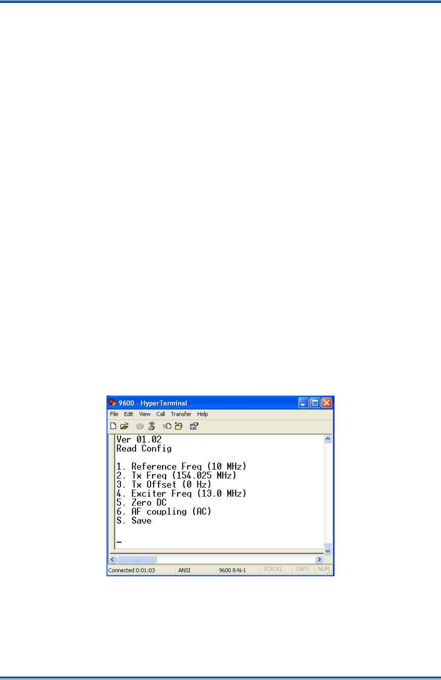
SGD-SB2025NT-TUM, Part 1
Jan 12 Page 42 ALIGNMENT & TESTING
1.1. Ensure that the power is switched off.
1.2. Refer to Appendix D and check that all the internal links are set correctly.
1.3. Check that the T36 External Reference option is correctly configured.
2. Using the T36 Module Serial cable, connect the PC with the HyperTerminal software or
similar serial communications program installed to the pin header HDR1 on the T36 Module
in the SB2025 base station.
3. Connect the Tx antenna connector to the RTS input.
4. On the PC, set the serial communications parameters to: 9600, 8, None, 1, None.
5. On the NI ET main window, check that the NI is not outputting any audio or tones by carrying
out the following:
5.1. Select the ‘Eng’ button to access the ‘NI Engineering’ window.
5.2. On the NI Engineering window, select the ‘Facilities’ tab.
5.3. On the ‘Facilities’ tab, check that the ‘Test Tone’ is disabled and that the ‘CTCSS Tone’
level is set to 0 (zero) (slider to minimum).
6. On the MxTools main window, on the tool bar, select the Channel Info icon. The Channel
screen will be displayed.
7. From the MxTools Channel screen, access the Channel Edit window and enter all of the
frequency pairs that are required for the SB2025 base station and select a channel in the
middle of the range of frequencies.
8. On the SB2025 base station, switch on the power and, on the PC, check that the following
HyperTerminal menu as shown below in Figure 5 is displayed.
Figure 5. HyperTerminal – Menu.
9. On the PC, using the HyperTerminal, carry out the following:
9.1. If not already set, adjust the ‘Tx Freq’ to the Tx frequency of the channel in use.
9.2. Ensure AF Coupling is set to AC. If necessary, press ‘6’ to toggle it.

SGD-SB2025NT-TUM, Part 1
Jan 12 Page 43 ALIGNMENT & TESTING
9.3. Press ‘5’ to zero the DC offset followed by ‘S’ to save the new settings.
10. On the MxTools main window, on the tool bar, select the Remote icon. The Remote page
will be displayed.
11. On the MxTools Remote page, select the ‘Software PTT’ button. A message will be
displayed warning that the radio will be keyed up for 2 minutes.
12. On the warning message, select the ‘OK’ button. The radio should transmit on the selected
channel.
13. On the RTS, ensure that the received carrier signal from the base station is as specified on
the radio base. Ensure that the ‘Tx Offset’ is less than 1 – 2 Hz, if necessary carry out the
following:
13.1. On the PC, using the HyperTerminal, use the < or > keys on the keyboard to adjust the
Tx Offset to zero.
13.2. When the Tx Offset is set to zero, press ‘S’ to save the settings.
14. On the TM ET, carry out the following:
14.1. On the Channel Status panel of the channel in use, select the ‘Setup’ button to access
the Channel Setup page.
14.2. On the Channel Setup page, on the ‘P25’ tab, using the drop-down list, set the Audio
Mode to Analogue and either 12.5 kHz or 25 kHz to match the SB2025 channel
bandwidth.
15. On the NI ET, carry out the following:
15.1. On the main window, select the ‘Eng’ button to access the ‘NI Engineering’ window.
15.2. On the NI Engineering window, select the ‘Main Audio’ tab,
15.3. On the Main Audio tab, ensure that the Audio Mode is set to ‘Remote’. If necessary,
use the drop-down list to change the audio mode (see Figure 6 below).
Figure 6. NI ET – Audio Mode to ‘Remote’.
16. Using the Analogue RTS, inject a signal at the appropriate Rx frequency, modulated at 100%
FM deviation at 1011 Hz at a level of -80 dBm into the Rx antenna socket of the SB2025.
Check that there is no CTCSS tone on this signal.
17. On the NI ET, on the Main Audio tab of the NI Engineering window, adjust the ‘In Audio
Sensitivity’ controls for an indication of 10,000 with the blue bar close to the middle of the
green section (see Figure 7 overleaf). Approximate settings are: the coarse control to 0 dB
and the fine control to around 112. (Expect small variations between receivers).
Note.
If the SB2025 is configured to use CTCSS, it will be necessary to temporarily change
Isolated Input #1 to ‘Monitor’ mode on the Signalling tab to make this adjustment.
Once the adjustment has been made, change it back to Auto mode immediately
afterwards.
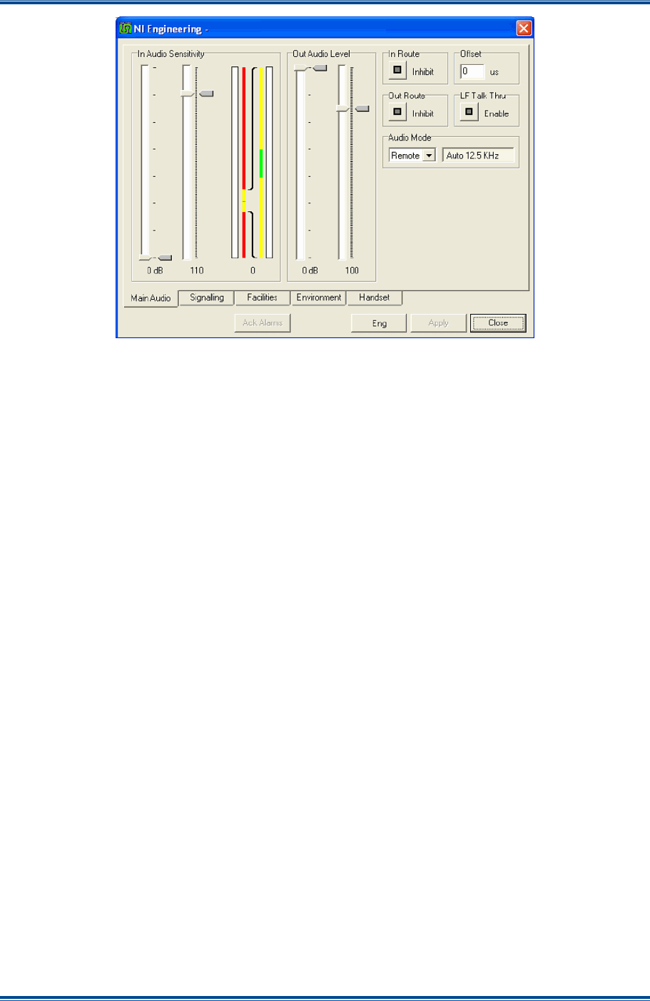
SGD-SB2025NT-TUM, Part 1
Jan 12 Page 44 ALIGNMENT & TESTING
Figure 7. NI Engineering – Main Audio tab, ‘In Audio Sensitivity’ settings.
18. On the SB2025 base station, connect the Analogue RTS to the Tx RF O/P.
19. On the NI ET, on the NI Engineering window, carry out the following:
19.1. On the Main Audio tab, carry out the following:
19.1.1. Set the Audio Mode to ‘Analog’.
19.1.2. Set the coarse and fine ‘Out Audio Level’ controls to 0 dB and 100
respectively.
19.2. On the Facilities tab, carry out the following:
19.2.1. Set the ‘CTCSS Tone’ slider to 0 (zero).
19.2.2. Set the Test Tone ‘Frequency’ to 1011 Hz and at a level of -4.4 dB.
19.2.3. Set the Test Tone Route to ‘External’ (see Figure 8 overleaf).
19.3. On the Signalling tab, select ‘Manual Trigger’ (see Figure 9 overleaf).
19.4. Select the ‘Apply’ button.
20. On the PC, start/open the MxTools software.
21. On the MxTools main window, on the tool bar, select the ‘Channel Info’ icon. The Channel
screen will be displayed.
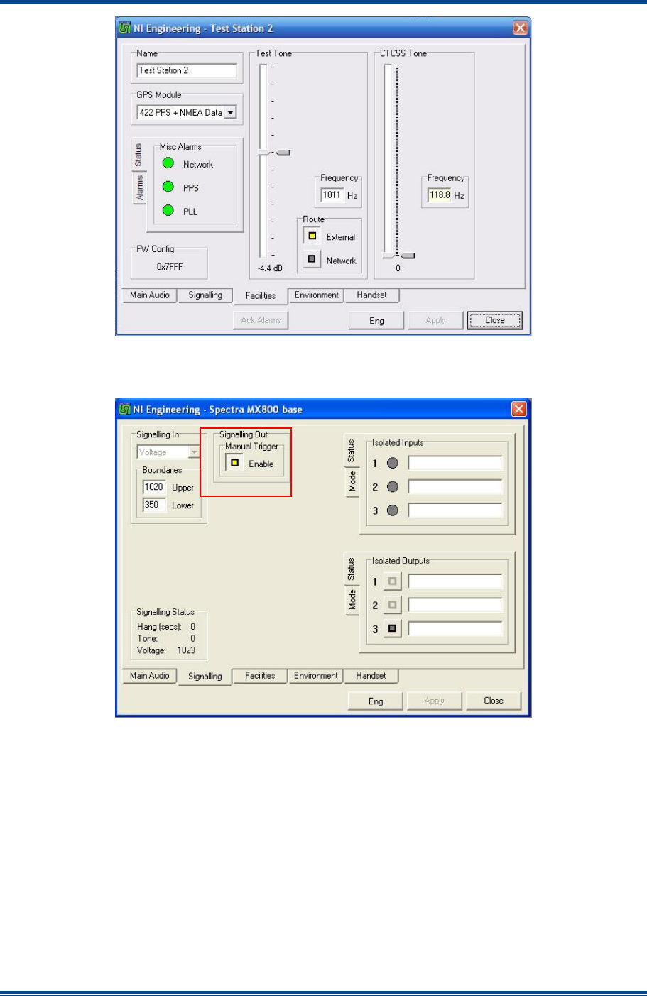
SGD-SB2025NT-TUM, Part 1
Jan 12 Page 45 ALIGNMENT & TESTING
Figure 8. NI Engineering – Facilities tab, Test Tone settings.
Figure 9. NI Engineering – Signalling tab, Manual Trigger.
22. On MxTools Channel screen, select channel No 1 and select the ‘Set Software Channel To’
tick button (see Figure 10 overleaf).
23. On the RTS, set it to either Auto Tune or to the Tx frequency.
24. On the PC, on the MxTools Channel screen, double click on channel No.1 to access the
Channel Edit screen.
25. On the Channel Edit screen, carry out the following:
25.1. Select the ‘Continuous Update Enabled’ tick box.
25.2. Set the ‘Ref Osc Level (LF Audio)’ digital potentiometer to 210.
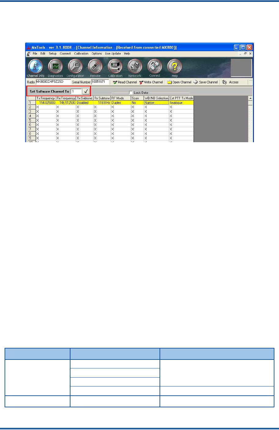
SGD-SB2025NT-TUM, Part 1
Jan 12 Page 46 ALIGNMENT & TESTING
25.3. Adjust the ‘VCO Level (LF Audio)’ digital potentiometer to obtain 1.5 kHz deviation on
the Radio Test Set.
25.4. Select the ‘OK’ button to accept the changes made and close the Channel Edit screen.
Figure 10. MxTools – Set Software Channel to tick button.
26. On the MxTools Channel screen, on the dynamic tool bar, select ‘Write Channel’ button to
save the changes made to the radio.
27. On the NI ET, on the Engineering window, carry out the following:
27.1. On the Facilities tab, set the Test Tone ‘Frequency’ to 200 Hz.
27.2. Select the ‘Apply’ button.
27.3. On the Facilities tab, check that the Test Tone ‘Frequency’ has changed to ‘MOD’
indicating that the SB2025 Modulation Balance test signal is being generated (see
Figure 11 overleaf). The SB2025 Tx will be keyed and modulated with a 200 Hz
square wave.
28. On the RTS, use a Wide Band AF Filter setting with a response of at least 15 kHz and
monitor the SB2025 Tx modulation.
29. On the PC, on the MxTools main window, on the tool bar, select the ‘Channel Info’ icon and,
on the channel table, double click on the channel in use to access the MxTools ‘Channel
Edit’ screen.
30. On the MxTools Channel Edit screen (see Figure 12 overleaf), adjust the various settings as
per Table 16 below.
Table 16. MxTools, Channel Edit Settings.
Area Setting Setting Required
TTR Channel
Simplex Channel
Scan Channel
All unchecked
RF Mode
Wide Band or Narrow Band As required (25 or 12.5 kHz bandwidth)
Frequency Settings
Tx Subtone (Hz) Disabled

SGD-SB2025NT-TUM, Part 1
Jan 12 Page 47 ALIGNMENT & TESTING
Figure 11. NI Engineering – Facilities tab, Test Tone Frequency.
Figure 12. MxTools – Channel Edit page.
31. On the MxTools Channel Edit screen, adjust the ‘Ref Osc Level (LF Audio)’ digital
potentiometer so that the top and bottom of the 200 Hz square wave displayed on the RTS is
as flat as possible (see Figure 13 overleaf).

SGD-SB2025NT-TUM, Part 1
Jan 12 Page 48 ALIGNMENT & TESTING
Figure 13. Typical result for Tx Modulation displayed on RTS.
32. DO NOT adjust the ‘VCO Level (VF Audio)’ digital potentiometer.
Note.
When making the adjustment in Para 31, any overshoot near the transitions can be
ignored.
33. On the MxTools Channel Edit page, when adjustment of the 200 Hz square wave is
completed, carry out the following:
33.1. Note the ‘Ref Osc Level (LF Audio)’ level as it will be used when setting the deviation
on all channels.
33.2. Select the ‘OK’ button.
Note.
When selecting the ‘OK’ button in the Para above, if any significant adjustment of the
‘Ref Osc Level (LF Audio)’ has been made in Para 31, an “Information” message will
be displayed advising that changes have been made and they have to be saved and
sent to the base station to take effect.
34. If the Information message is displayed, select the ‘OK’ button to save the changes and
prepare the data to be sent to the base station.
35. On the MxTools main window, on the dynamic tool bar, select the ‘Write Channel’ button to
store the settings back to the SB2025 base station.
36. On the NI ET, on the NI Engineering window, carry out the following:
36.1. On the Facilities tab, set the ‘Test Tone’ to a frequency of 1011 Hz and to a level of
−4.4 dB. Set the Route to ‘External’ (see Figure 8).
36.2. Select the ‘Apply’ button.
37. On the MxTools Channel screen, select one of the configured channels and carry out the
following:
37.1. On the MxTools Channel screen, select the ‘Set Software Channel To’ tick button.

SGD-SB2025NT-TUM, Part 1
Jan 12 Page 49 ALIGNMENT & TESTING
37.2. On the RTS, check that it is set to Auto tune or re-tune to the require frequency.
37.3. On the MxTools Channel screen, double click on the select channel to access the
Channel Edit screen.
37.4. On the Channel Edit screen, carry out the following:
37.4.1. Select the ‘Continuous Update Enabled’ tick box.
37.4.2. Set the ‘Ref Osc Level (LF Audio)’ digital potentiometer to value noted earlier
in Para 33.1.
37.4.3. Adjust the ‘VCO Level (LF Audio)’ digital potentiometer to obtain 1.5 kHz
deviation on the Radio Test Set.
37.4.4. Select the ‘OK’ button to accept the changes made and close the Channel Edit
screen.
37.5. On the MxTools Channel screen, on the dynamic tool bar, select ‘Write Channel’ button
to save the changes made to the radio.
38. Repeat Para 37 to Para 37.5 for all the configured channels.
39. On the NI ET, on the Engineering window, carry out the following:
39.1. On the Facilities tab, set the Test Tone ‘Frequency’ to 200 Hz.
39.2. Select the ‘Apply’ button.
40. On the Facilities tab, check that the Test Tone ‘Frequency’ has changed to ‘MOD’ indicating
that the SB2025 Modulation Balance test signal is being generated.
41. On the MxTools Channel screen, select one of the configured channels and carry out the
following:
41.1. On the MxTools Channel screen, select the ‘Set Software Channel To’ tick button.
41.2. On the RTS, check that it is set to Auto tune or re-tune to the require frequency.
41.3. On the RTS, use a Wide Band AF Filter setting with a response of at least 15 kHz and
monitor the SB2025 Tx modulation.
41.4. On the MxTools Channel screen, double click on the select channel to access the
Channel Edit screen.
41.5. On the MxTools Channel Edit screen, carry out the following:
41.5.1. Adjust the ‘Ref Osc Level (LF Audio)’ digital potentiometer so that the top and
bottom of the 200 Hz square wave displayed on the RTS is as flat as possible.
Note.
When making the adjustment in Para 41.5.1 above, only a small adjustment of the ‘Ref
Osc Level (LF Audio)’ control should be required to achieve the required square wave.
41.5.2. DO NOT adjust the ‘VCO Level (VF Audio)’ digital potentiometer.

SGD-SB2025NT-TUM, Part 1
Jan 12 Page 50 ALIGNMENT & TESTING
41.5.3. Select the ‘OK’ button to accept the changes made and close the Channel Edit
screen.
41.6. On the MxTools Channel screen, on the dynamic tool bar, select ‘Write Channel’ button
to save the changes made to the radio.
42. Repeat Para 41 to Para 41.6 for all the configured channels.
43. On the NI ET, on the NI Engineering window, carry out the following:
43.1. On the Facilities tab, set the ‘Test Tone’ to a frequency of 1011 Hz and to a level of
−4.4 dB. Set the Route to ‘External’.
43.2. Select the ‘Apply’ button.
44. On the MxTools Channel screen, select one of the configured channels and carry out the
following:
44.1. On the MxTools Channel screen, select the ‘Set Software Channel To’ tick button.
44.2. On the RTS, carry out the following:
44.2.1. Check that it is set to Auto tune or re-tune to the require frequency.
44.2.2. Check that the deviation of the 1011 Hz tone is 1.5 kHz.
45. Repeat Para 44 to Para 44.2.2 for all the configured channels.
Note.
After successful completion of the above procedure, the ‘Ref Osc Level (LF Audio)’
digital potentiometer slider should be at approximately the same level on all channels.
The ‘VCO Level (VF Audio)’ digital potentiometer slider will be set lower on higher
frequency channels as the SB2025 produces greater modulation on higher
frequencies. The deviation should be the same on all channels with a constant level in
from the NI.
6.1.10 Mute Threshold Setting
The Mute Threshold Setting RV6 is used to set the level at which the mute opens.
Procedure
1. On the MxTools main screen, on the tool bar, select the ‘Remote’ icon. The Remote screen
will be displayed.
2. On the Remote screen, select the Mute Control ‘Open’ button to force the mute open.
3. Inject the correct RF frequency into the Rx for the test channel.
4. Set the Rx modulation frequency to 1 kHz at nominal deviation.
5. Alter the amplitude of the RF signal until the Rx audio has an 8 dB Signal to Noise and
Distortion (SINAD).
6. On the MxTools Remote Screen, select the Mute Control ‘Normal’ button to set the mute
back to normal.

SGD-SB2025NT-TUM, Part 1
Jan 12 Page 51 ALIGNMENT & TESTING
7. Adjust the mute level potentiometer, RV6, until the mute opens then wind it back until it just
closes.
New Motherboards (PCB Rev >R), have a new software digital controlled mute function. This
provides the user with the ability to program the SB2025NT with three different mute settings.
These setting can be changed on the fly by a PC when connected via RS232. These controls are
located within MxTools Configuration screen, under Mute/Squelch settings tab. They are named
as ‘NORMAL’, ‘User Preset 1’ and ‘User Preset 2’. Please see MxTools help screen for further
assistance in setting these presets.

SGD-SB2025NT-TUM, Part 1
Jan 12 Page 52 ALIGNMENT & TESTING
6.2 M
ODULE
L
EVEL
T
EST
P
ROCEDURES
The following alignment and testing procedures are based upon using a working transceiver as the
test environment. It is also assumed that test fixtures to the radio are available to exercise control
lines and monitor outputs and that a PC with MxTools is connected to the radio.
There are four modules in the SB2025 – the Exciter, Rx, PA and Micro Controller. The Exciter and
the Rx have VCO daughter boards. The Rx and Exciter VCOs are similar.
6.2.1 Exciter Module
Test Equipment Required:
• Tested SB2025NT with Exciter removed.
• Tested Tx VCO board (in wanted band).
• PC with MxTools software.
• RF Communications Test Set (CTS).
• Multimeter.
• Oscilloscope.
• +13.8 VDC Power Supply.
Preliminaries:
1. On the MxTools Channel screen, program the upper, middle and lower frequencies of the
frequency band (refer to Appendix A for band split details) into three channels.
Note.
The ‘Continuous Update Enabled’ option on the MxTools Channel Edit screen should
be selected for these tests.
2. Remove the top cover from Exciter module under test and fit a known working VCO tuned for
the band to be tested.
3. Connect the Exciter to a working Micro Controller via 16-way ribbon cable.
4. Disconnect Exciter RF drive output CN1 from PA.
Procedure
5. Switch on DC power and check that the output voltage on pin 1 of IC5 is 5 V ± 0.2 V and that
the output voltage on pin 1 of IC3 and IC8 is 8 V ± 0.2 V.
6. Assert PTT and check that 8 V is switched through to SKU-3.
7. On the centre pin pad of CN3, check that the reference oscillator signal is >3 Vp-p.
8. Select the mid channel.
9. Connect the CTS RF input port to CN1.
10. Assert PTT and check that Lock Detect (LD) on SKD-16 goes high indicating that the loop is
locked.
11. Check that the power control volts on SKD-4 is >10 V and that the RF output on CN1 is
>300 mW.

SGD-SB2025NT-TUM, Part 1
Jan 12 Page 53 ALIGNMENT & TESTING
12. On the MxTools Channel Edit screen, adjust the ‘Tx RF Power’ digital potentiometer slider to
0 (zero) and check that the power control volts on SKD-4 drops to 0 V and that the RF power
out drops to <1 mW.
13. On the MxTools Channel Edit screen, set the the ‘Tx RF Power’ digital potentiometer slider
back to mid position.
14. Select the lowest channel.
15. Assert PTT and check that LD goes high and that the VCO tuning volts on SKD-14 is >2 V.
16. Select the highest channel.
17. Assert PTT and check that LD goes high and that the VCO tuning volts on SKD-14 is <18 V.
Check that the RF output in both cases is >300 mW.
18. Select the mid channel.
19. Assert PTT. Note the RF output carrier frequency.
20. On the MxTools Channel Edit screen, check that, by adjusting the ‘Ref Osc Freq’ digital
potentiometer slider, the carrier frequency can be adjusted to ±3 ppm of the nominal
frequency.
21. Select the mid channel.
22. Assert PTT and carry out the Section 6.1.9 – Peak Deviation and Modulation Balance part
of the Tx VF alignment procedure to check the function of the VCO and Reference oscillator
modulation inputs.
6.2.2 Receiver Module
Test Equipment Required:
• Tested SB2025NT with Rx removed.
• Tested Rx VCO board (in wanted band).
• PC with MxTools software installed.
• RF Communications Test Set.
• Spectrum Analyser with Tracking Generator.
• Multimeter.
• High Frequency (89.545 MHz) Pick up Loop.
• Oscilloscope.
• +13.8 VDC Power Supply.
Preliminaries
1. On the MxTools Channel screen, program the upper, middle and lower frequencies of the
frequency band (refer to Appendix A for band split details) into three channels.
Note.
The ‘Continuous Update Enabled’ option on the MxTools Channel Edit screen should
be selected for these tests.

SGD-SB2025NT-TUM, Part 1
Jan 12 Page 54 ALIGNMENT & TESTING
2. Remove the top cover from Exciter module under test and fit a known working VCO tuned for
the band to be tested.
3. Connect the Exciter to a working Micro Controller via 16-way ribbon cable.
Procedure
The test procedure for the Rx is divided into the Front-end Alignment and the IF Alignment
procedures.
Front-end Alignment
4. Switch on the DC power and check that the output voltage on pin 1 of IC8 is 5 V ± 0.2 V, on
pin 1 of IC2 is 8 V ± 0.2 V, on output of IC9 (on C66) is 8 V ± 0.2 V and on pin 1 of IC3 is 9 V
± 0.2 V.
5. Remove Jumpers E and D, and install Jumper C.
6. Connect the Tracking Generator output to CN1 and Spectrum Analyser input to CN4.
7. Set the Tracking Generator to sweep the band.
8. Adjust A4, A10 and A16 for a symmetrical pass-band around the band centre frequency.
9. Check that the gain over the band is 12 dB and that the ripple is < ±1.5 dB.
10. Check that the attenuation at the first IF image is >50 dB.
11. Remove Jumpers C and I, and install Jumpers E and H.
12. Connect the Tracking Generator output to CN4 and Spectrum Analyser input to CN5.
13. Set the Tracking Generator to sweep the band.
14. Adjust B4, B10 and B16 for a symmetrical passband around the band centre frequency.
15. Check that the maximum loss over the band is <3 dB and that the attenuation at the first IF
image is >50 dB.
16. Remove Jumper E and install Jumper D.
17. Connect the Spectrum Analyser input to CN5 and Tracking Generator output to CN1.
18. Set tracking generator to sweep the band.
19. Check for symmetrical passband around band centre frequency.
20. Check that the gain over the band is 10 dB and that the ripple is <1.5 dB.
21. Remove Jumper H and install Jumper J.
IF Alignment
22. Select the mid channel.
23. Check that LD on SKD-16 goes high indicating that the synthesiser is in lock.
24. Remove S3 (0 Ω local oscillator connection to mixer) and solder a 50 Ω coax test lead across
C60 position (Note C60 position is near a retaining screw and C60 is not fitted).

SGD-SB2025NT-TUM, Part 1
Jan 12 Page 55 ALIGNMENT & TESTING
25. Connect the CTS to this lead and check that the RF local oscillator power is +17 dBm ± 2dB.
26. Measure the local oscillator frequency, this should be F
RX
-90 MHz. Using a non-metallic
trimmer tool carefully adjust the TCXO (X2) frequency until the correct frequency is obtained.
27. Remove the test lead and solder S3 back in position.
28. Place the high frequency pick up loop in close proximity to IC1 in order to pick up the second
IF oscillator frequency (do not probe directly on the chip as test lead capacitance will affect
oscillator frequency).
29. Adjust CT1 for 89.545 MHz.
30. Inject an RF signal at -80 dBm (un-modulated) at F
RX
into CN5 (Jumper I out, Jumper J in).
31. Measure the DC voltage at VF output SKD-3 and ensure it is 2.5 V. If necessary, adjust L14
for the required voltage.
32. Inject an RF signal at -80 dBm with standard modulation at F
RX
into CN5.
33. Monitor the line Rx out and adjust T1 and T2 for minimum distortion.
34. Reduce the RF signal level and check that sensitivity is better than -112 dBm for 12 dB
SINAD.
35. Remove Jumper J and install Jumper I.
36. Inject an RF signal with standard modulation at F
RX
into CN1.
37. Monitor the line Rx out and check that sensitivity is better than -117 dBm for 12 dB SINAD.
38. Repeat the IF Alignment test for the upper and lower channels.
6.2.3 Power Amplifier Module
Test Equipment Required
• Tested SB2025NT with PA removed.
• PC with MxTools software.
• RF Power Meter.
• RF Signal Generator.
• Multimeter.
• +13.8 VDC, 15 A Power Supply.
Preliminaries
1. On the MxTools Channel screen, program the upper, middle and lower frequencies of the
frequency band (refer to Appendix A for band split details) into three channels.
Note.
The ‘Continuous Update Enabled’ option on the MxTools Channel Edit screen should
be selected for these tests.
2. Do not connect the Exciter RF drive output CN1 to the PA.

SGD-SB2025NT-TUM, Part 1
Jan 12 Page 56 ALIGNMENT & TESTING
Procedure
3. Remove PA top cover.
4. Measure the resistance of the thermistor between CN4-6 and CN4-4, this should be
approximately 2 kΩ.
5. Connect DC power lead and 10-way connector from SB2025NT.
6. Connect the PA RF output to the RF Power Meter and the PA RF input (CN1) to RF Signal
Generator.
7. Set the Signal Generator to centre frequency of PA under test and reduce the RF drive level
(from signal generator) to zero.
8. Switch on DC power and check that supply is present on L6.
9. Assert PTT (check that no output RF power is emitted from the PA) and check that the
13.8 V supply is switched through to source of TR1 and TR2.
10. With PTT ON, measure the PA bias current at the gates of the Field Effect Transistors
(FETs). The Bias current is band dependent. This is done by monitoring the current drain of
the whole PA with CN1 disconnected.
11. Link the gate of TR2 to GND.
12. Measure current consumption (VHF Low Band 400 mA, VHF High Band 200 mA, UHF
400 mA.) This can be adjusted by RV2. Measure gate volts ≈ 3.4 V.
13. Remove link from TR2.
14. Measure the current consumption and adjust RV1 so that current is 2 Amp total for the VHF
High Band & UHF Band, and 1 Amp for VHF Low Band. Measure gate volts ≈ 3.9 V.
15. With PA transmitting at 50 W into 50 Ω load, measure DC volts FWD power sense CN4-8
and REFL power sense CN4-5. These voltages should be approx. 2.8 V and <250 mV
respectively.
16. Reduce the RF drive until the PA output is 10 W. Disconnect the PA RF output cable.
17. Measure the DC voltage on CN4-8 and CN4-5 again. These should now both read lower
approximately 1 V.
18. Remove PTT.
6.2.4 VCO Board
Test Equipment Required
• Tested SB2025NT with Exciter VCO removed.
• PC with MxTools software installed.
• RF Communications Test Set.
• Multimeter.
• Oscilloscope.
• +13.8 VDC Power Supply.

SGD-SB2025NT-TUM, Part 1
Jan 12 Page 57 ALIGNMENT & TESTING
Preliminaries
1. On the MxTools Channel screen, program the upper, middle and lower frequencies of the
frequency band (refer to Appendix A for band split details) into three channels.
Note.
The ‘Continuous Update Enabled’ option on the MxTools Channel Edit screen should
be selected for these tests.
2. Remove the top cover from Exciter module and fit the VCO under test. As the Tx and Rx
VCOs are identical, the Rx VCO may also be tested in an Exciter. As the Rx VCO operates
at the frequencies F
RX
– 90 MHz.
3. Connect the Exciter to a working Micro Controller via 16-way ribbon cable.
4. Disconnect Exciter RF drive output CN1 from PA.
Procedure
5. Select mid channel.
6. Connect SKU from the Exciter to VCO.
7. Switch on the DC power.
8. Assert PTT and measure the RF output power on VCO SKT-6. This should be in the range
0 dBm to +3 dBm.
9. Measure the RF output level on SKU-1. This should be in the range 0 dBm to +3 dBm.
Note.
If SKU-1 is disconnected from the Exciter the loop will lose lock.
10. Reconnect SKT and SKU to Exciter.
11. Select lower channel.
12. Assert PTT and check that loop is locked.
13. Adjust trim cap CT1 on VCO for 3 VDC (2 VDC for N2 band) on SKT-1.
14. Select upper channel and check that the loop is locked and that the voltage on SKT-1 is
<18 VDC.
The following test is not required for the Rx VCO.
15. Connect the Exciter output to the CTS. Inject 1 kHz tone at nominal line input level and
check that Exciter RF output is modulated and that the depth of modulation can be controlled
through the MxTools Channel screen.
6.2.5 Microcontroller Module
Comprehensive testing of the Micro Controller can only be carried out at the Factory.

SGD-SB2025NT-TUM, Part 1
Jan 12 Page 58 FAULT FINDING
7 FAULT FINDING PROCEDURES
The following test equipment may be required for the tests detailed in this section:
• PC with MxTools (SB2025 Base Station Programming Utility).
• RF Test Set (e.g. HP 8920 or equivalent).
• Oscilloscope.
• RF Power Meter (capable of measuring to 60 Watts continuously).
• Multimeter.
• +13.8 V DC Power Supply (capable of supplying 15 Amps).
• Network Analyser.
• SB2025 Test Jig (Optional).
7.1 SB2025
B
ASE
S
TATION
The following tests will help diagnose faulty modules.
1. Check that all of the required connections to the SB2025 Radio are made.
2. Check that all of the interconnecting cables to each of the modules and to the Motherboard
are correctly installed.
3. Check the voltage supply to the SB2025 by measuring both sides of Fuse 1 located on the
Micro Controller PCB. If necessary, replace the fuse.
4. Check that the ‘PWR’ LED is lit. If not, go to Section 7.2.
5. Using MxTools, check that the frequency tables and configuration settings are correct.
7.1.1 Transmitter Section
1. Connect the output of the PA Module to a Comms test set or a RF power meter.
2. Using MxTools Diagnostic’s, check the Tx VCO locking voltage is between 2 V – 18 V and
there is no Tx VCO ‘Unlock’ alarm displayed.
3. If the locking voltage is out of specification or an ‘Unlock’ alarm is displayed then go to
Section 7.4.
4. Using the Software PTT in MxTools, key up the Tx.
5. If the output power of the SB2025 is LOW, using MxTools, check that the ‘Transmit Power’
control is not on a low setting.
6. Adjust the ‘Transmit Power’ control towards maximum looking for an increase in the RF
power output level. If there is no substantial change, go to the diagnostics screen and check
that the Forward power and the Reflected power levels are not abnormal.
Note.
If there is a high reflected power indication, the SB2025 Firmware would hold the PA
power low.

SGD-SB2025NT-TUM, Part 1
Jan 12 Page 59 FAULT FINDING
7. If the Diagnostics shows abnormal, on the Motherboard, check the voltage on pin 62 of IC1.
If the voltage is low (i.e. <200 mV), the likely fault is IC1. If the voltage is >200 mV, the likely
fault is within the PA module.
8. If the Diagnostics shows normal, check the RF level from the Exciter module by connecting a
Power Meter directly to the Exciter RF connector. In MxTools, adjust the ‘Transmit Power’
control to maximum, the RF level should be >+23 dBm (200 mW). If the RF level is correct,
the PA is probably faulty, go to Section 7.5. If the RF level is not correct, go to Section 7.4.
9. If there is No RF power output, in MxTools, check that the ‘Transmit Power’ control has not
been set to 0 (zero) or at a very low level. If so, apply a PTT and increase the power control
until the desired power is achieved. If not, apply a PTT then check that pin 21 of IC1 is LOW,
collector of TR3 is LOW and pin 13 of IC7 is HIGH. If these are OK, the Exciter or PA may
be faulty. Go to Section 7.4, or Section 7.5.
10. Using the Engineering Terminal, inject a 1011 Hz tone @ –4.4 with route set to ‘External.
11. If the audio deviation is incorrect, go to the Tx alignment procedure in Section 6.
12. If there is no audio modulation, check the audio level on pin 13, IC11on the Micro Controller
PCB.
13. If there is no audio on the above test point, go to Section 7.2, otherwise, go to Section 7.4.
7.1.2 Receiver Section
1. Using MxTools Diagnostic’s, check the Rx VCO locking voltage is between 2 V – 18 V and
there is no Rx VCO ‘Unlock’ alarm displayed.
2. If the Rx locking voltage is out of specification, go to Section 7.3.
3. Inject a –60 dBm RF test signal at the Rx frequency and modulated with a 1 kHz tone @ 1.5
kHz (NB)/3 kHz (WB) deviation into the Rx input connector on the rear of the radio.
4. Check for an audio signal @ -10 dBm on pin 15 of the DB15 connector on the rear of the
SB2025.
5. If there is an audio signal @ -10 dbm, check the Rx for correct SINAD, Signal to Noise Ratio
(SNR), Audio Distortion and Mute operation. Refer to Section 7.3.
6. If there is no audio signal, inject the test signal directly into the Rx module and re-test for an
audio signal on the SB2025 test jig.
7. Replace the Rx input coax cable if faulty.
8. Check for an audio signal on pin 2 of SKK on the Micro Controller PCB. If the audio signal is
not present, it indicates a Rx fault, go to Section 7.3.
9. If there is a signal present at this point, it indicates a fault with the Motherboard audio or mute
operation, go to Section 7.2.
7.2 M
ICRO
C
ONTROLLER
PCB
1. Check the fuse. If blown, replace with a 5x20 mm 3 A fast blow fuse.
2. Check all jumpers and switch settings are in the correct position for your requirements.

SGD-SB2025NT-TUM, Part 1
Jan 12 Page 60 FAULT FINDING
3. The Micro Controller PCB requires specialised test software to check all the hardware input
and output ports. Please contact Simoco Customer Services and arrange for the Micro
Controller PCB to be returned to Simoco’s Service Centre.
7.3 R
ECEIVER
M
ODULE
7.3.1 VCO Locking.
1. In MxTools, check that all hardware settings are correct.
2. On the Rx Module, check the value of X3 (13 MHz or 14.4 MHz) is the same as the Rx
Reference Frequency in the ‘Hardware Settings’ on the MxTools configuration menu.
3. On the Microcontroller PCB, connect a Digital Voltmeter (DVM) to the Rx VCO TP and check
the Rx locking voltage is between 2 V – 18 V.
4. Check that +12 V (SKD-2) and 28 V (SKD-13) supply lines are present.
5. If the Rx locking voltage is out of specification, on the Rx VCO, slowly adjust CT1 a full 360°
and check for a change in the locking voltage.
6. If there is a change in the Rx VCO locking voltage, realign the VCO voltage to 9 V at the
centre frequency of the Rx band.
7. If there is no change in the Rx VCO locking voltage, check that the VCO supply voltage at
SKU-3 is approximately 7 V and, with an Oscilloscope, check the TCXO is oscillating on pin
8 of IC10.
8. If all the above tests fail, the VCO or IC10 may be faulty. Contact Simoco Customer
Services and arrange for the Rx Module to be returned to Simoco’s Service Centre.
7.3.2 Rx Front End
1. Solder a 2-way Berg header onto a flying coax lead. Remove solder link I near the mixer
(M1) and fit solder link J. Inject a RF signal into CN5. Check that the sensitivity is better
than –110 dBm.
2. If the sensitivity is OK past this point, check that the supply voltage to IC12 is approx. 8 V. If
the supply is OK, replace IC12. If this does not repair the Rx, the alignment may be incorrect
or other components on the front end may be faulty. Go to Section 6.2.2.
7.3.3 IF Section
1. If the Rx has low sensitivity past this point, increase the RF level to –60 dBm and ensure the
Rx DISC voltage is set to 2.50 V. If necessary, adjust L14 for the required voltage.
2. Connect a coax lead with a pickup loop around the end from the antenna input on the
HP8920A to the case of X1. Set the HP8920 to Tx test, change the Tune Mode to Manual
and change the centre frequency of the CTS to 44.545 MHz for A to B Band and 89.545 MHz
for C Band and above.
3. If CT1 cannot be adjusted to match the above frequencies, X1 may be faulty.
4. Set the centre frequency of the HP8920A to the Rx freq. + 45 MHz for A to B band or Rx
freq. + 90 MHz for C to M Band or Rx freq. – 90 MHz for N band and above.
5. Adjust the TCXO to within ± 20 Hz.
6. If the Rx centre frequency cannot be adjusted, the TCXO may be faulty.

SGD-SB2025NT-TUM, Part 1
Jan 12 Page 61 FAULT FINDING
7. Adjust T1 and T2 for minimum distortion <1%.
8. If the distortion is high, FL3A, FL3B or FL4 may be faulty.
9. If the sensitivity is still poor, contact Simoco Customer Services and arrange for the Module
to be returned to Simoco’s Service Centre.
7.4 E
XCITER
M
ODULE
7.4.1 VCO Locking
1. On the Exciter module, check the reference frequency of X3 (13 MHz or 14.4 MHz) is the
same as the Tx Reference Frequency in the ‘Hardware Settings’ on the MxTools
configuration menu.
2. On the Micro Controller PCB, connect a DVM to the ‘TX VCO’ test point and check the Tx
locking voltage is between 2 V – 18 V.
3. Check that +12 V (SKD-2) and 28 V (SKD-13) supply lines are present.
4. If the Tx locking voltage is out of specification, on the Tx VCO, slowly adjust CT1 a full 360°
and check for a change in the locking voltage.
5. If there is a change in the Tx VCO locking voltage, realign the VCO voltage to 9 V at centre
frequency of the VCO frequency band.
6. If there is no change in the Tx VCO locking voltage, check the VCO supply voltage at SKU-3
is approx. 7 V and, with an Oscilloscope, check the TCXO is oscillating on pin 8 of IC 10.
7. If all the above tests pass, the VCO or IC10 may be faulty. Contact Simoco Customer
Services and arrange for the Exciter Module to be returned to Simoco’s Service Centre.
7.4.2 RF Power
1. Using MxTools increase the ‘Transmit Power’ control to maximum and check that the output
power is greater than +24 dBm.
2. If the Exciter power is low, check for the +8 V supply voltage at the outputs of IC2 and TR4.
3. Use a RF probe to check for gain through IC2 and TR4.
4. Lift R2 and solder a flying lead to the junction of R1 and R2. Check the output power of the
VCO is between 0 and +3 dBm.
5. If all the above tests pass, contact Simoco Customer Services and arrange for the Exciter
Module to be returned to Simoco’s Service Centre.
7.5 P
OWER
A
MPLIFIER
1. Firstly, carry out a visual inspection of all the components on the PA looking for any
damaged components.
2. Connect the input of the PA to signal generator with the RF output switched off.
3. With PTT off, measure the +13.8 V supply at the source of the driver and output FET. If out
of specification, check voltage at CN2-2, if no volts check the supply cable.

SGD-SB2025NT-TUM, Part 1
Jan 12 Page 62 FAULT FINDING
4. With PTT ON, measure the PA bias current at the gates of the FETs. The bias current is
band dependent. This is done by monitoring the current drain of the whole PA with CN1
disconnected. Link the gate of TR2 to GND. Measure current consumption (VHF High Band
200 mA, VHF low and UHF 400 mA). This can be adjusted by RV2. Measure gate volts
≈ 3.4 V.
5. Remove the link from TR2. Measure the current consumption and adjust RV1 so that current
is 2 Amp total (VHF & UHF) and VHF Low 1 Amp. Measure gate volts ≈ 3.9 V.
6. Using a coax lead, connect the RF output connector CN3 to a power meter. Turn on the
supply voltage and the signal generator RF output. PTT the PA and increase the generator
output (do NOT exceed +24 dBm) whilst measuring the output power output (≥50 watts @
+24 dBM).
7. If the output power is low, turn the supply voltage OFF and lift one side of the capacitors
connecting to the directional coupler and solder a flying lead to the lifted side. Connect the
earth of the flying lead to the earth of the PA. Connect the power meter to the flying lead.
8. Turn on the supply voltage and the signal generator RF output. PTT the PA and increase the
generator output (do NOT exceed +24 dBm) whilst measuring the output power output
(≥55 watts @ +24 dBM).
9. If all the above tests fail, TR1 or TR2 may be faulty. Contact Simoco Customer Services and
arrange for the PA to be returned to Simoco’s Service Centre.

SGD-SB2025NT-TUM, Part 1
Jan 12 Page 63 DRAWINGS
8 DRAWINGS
8.1 C
URRENT
D
RAWINGS
Table 17. Drawings.
Drawing No.
Description Band
Figure 14 Rx Component Overlay All
Figure 15 Exciter Component Overlay All
Figure 16 PA Component Overlay (Superseded Version) A to Q
Figure 17 PA Component Overlay (New Wide Band Version)
Figure 18 Micro Controller Component Overlay (Rev S) All
Figure 19 Tx and Rx VCO Component Overlay A to Q3
Figure 20 Tx and Rx VCO Component Overlay R to X
Figure 21 HP Rx VCO Component Overlay A to Q
Figure 22 Tx/Rx V3 VCO Component Overlay All
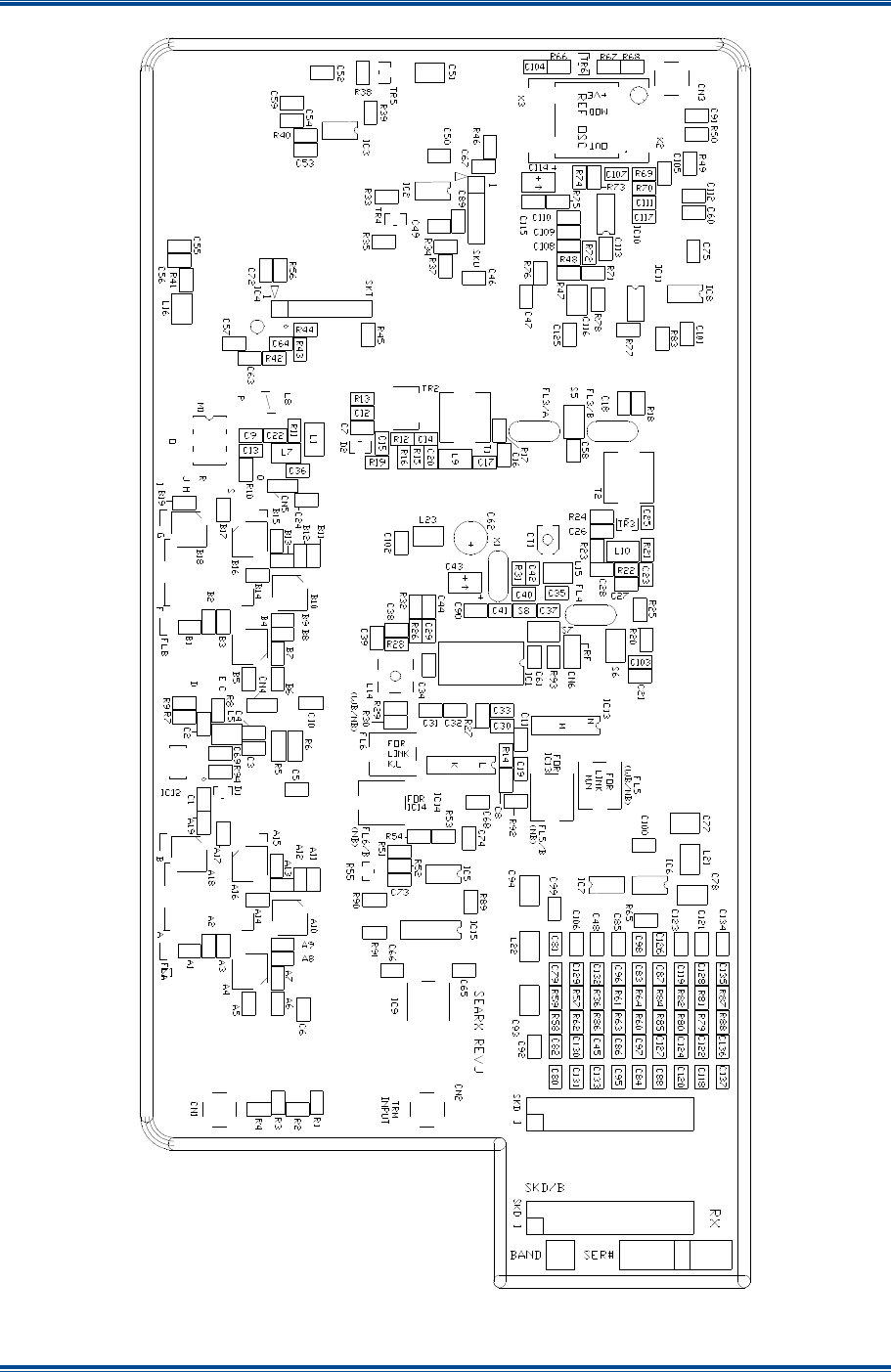
SGD-SB2025NT-TUM, Part 1
Jan 12 Page 64 DRAWINGS
Figure 14. Rx Component Overlay.
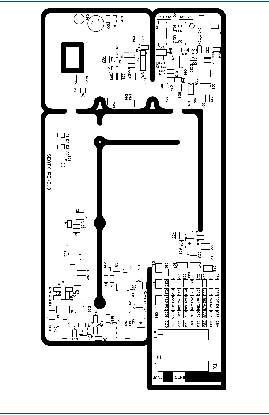
SGD-SB2025NT-TUM, Part 1
Jan 12 Page 65 DRAWINGS
Figure 15. Exciter Component Overlay.
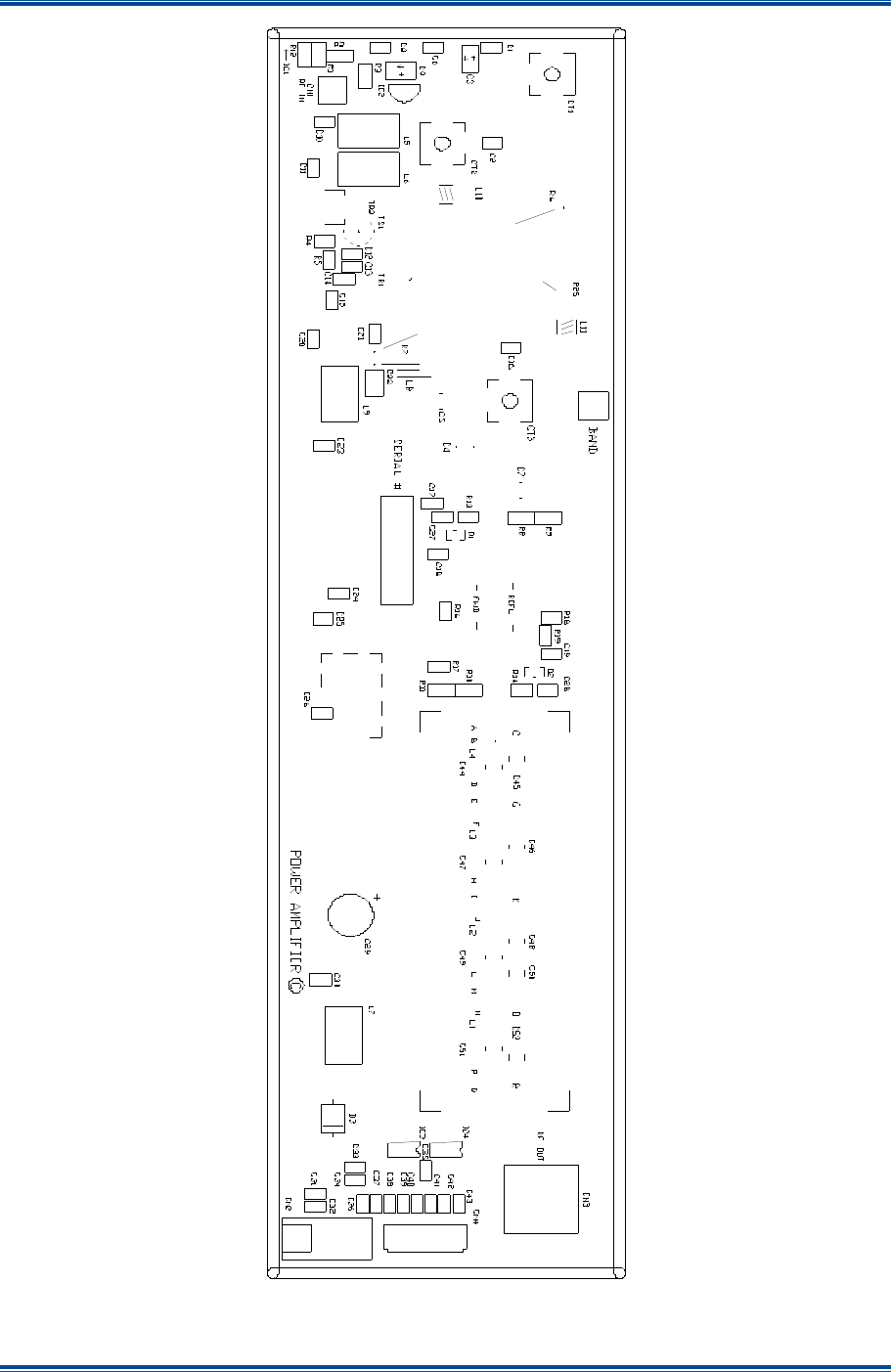
SGD-SB2025NT-TUM, Part 1
Jan 12 Page 66 DRAWINGS
Figure 16. PA Component Overlay – Superseded Version.
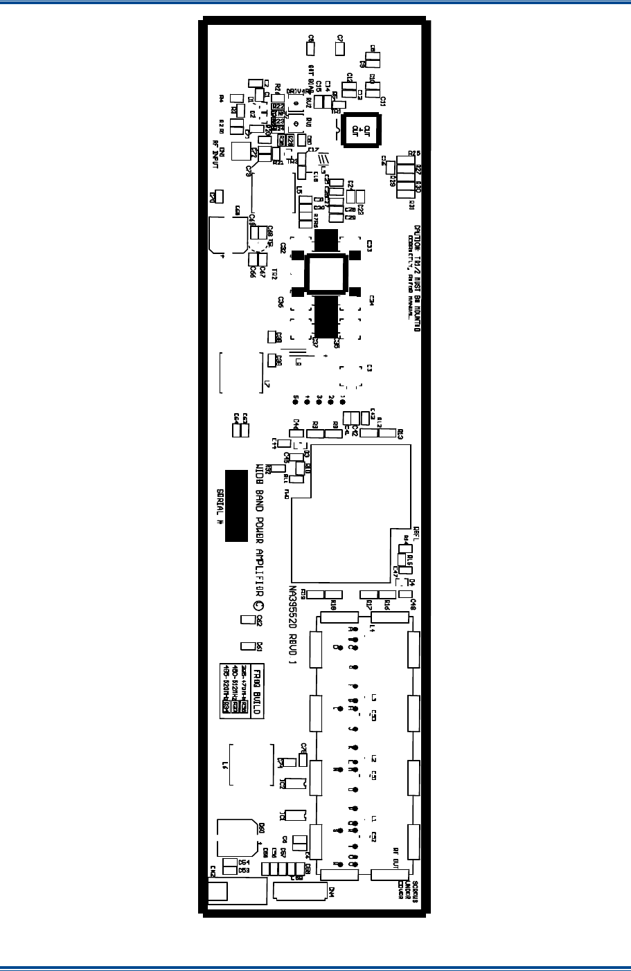
SGD-SB2025NT-TUM, Part 1
Jan 12 Page 67 DRAWINGS
Figure 17. PA Component Overlay – New Wide Band PA Version.

SGD-SB2025NT-TUM, Part 1
Jan 12 Page 68 DRAWINGS
Figure 18. Micro Controller Component Overlay (Rev S).
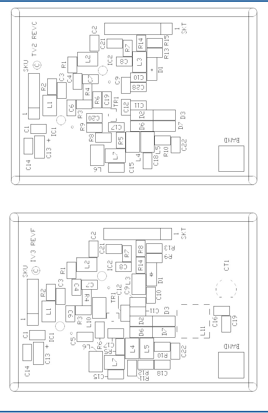
SGD-SB2025NT-TUM, Part 1
Jan 12 Page 69 DRAWINGS
Figure 19. Tx and Rx VCO Component Overlay Bands A to Q3.
Figure 20. Tx and Rx VCO Component Overlay Bands R to X.
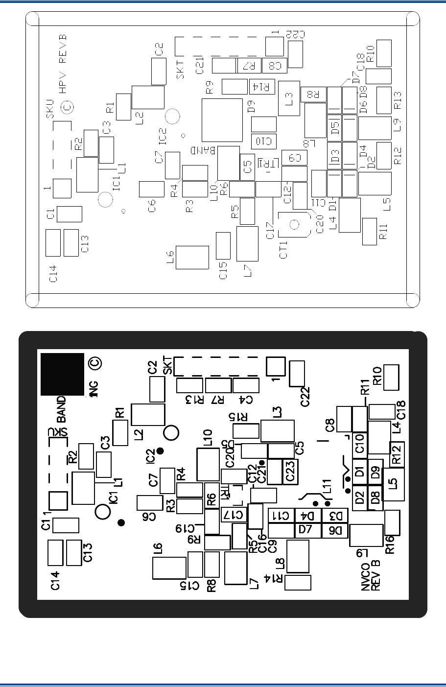
SGD-SB2025NT-TUM, Part 1
Jan 12 Page 70 DRAWINGS
Figure 21. HP Rx VCO Component Overlay Bands A to Q.
Figure 22. Tx/Rx V3 VCO Component Overlay.

SGD-SB2025NT-TUM, Part 1
Jan 12 Page 71 SPARES
9 SPARES
To be advised.

SGD-SB2025NT-TUM, Part 1
Jan 12 Page 72 APPENDIX A
APPENDIX A
SB2025 FREQUENCY BANDS
The frequency bands available for the SB2025 are specified in Table A-1 below.
Table A-1. SB2025 Frequency Bands.
Band Frequency
(MHz) Band Frequency
(MHz) Band Frequency
(MHz) Band Frequency
(MHz)
A2 30 – 39 G 220 – 250 O 425 – 460 R3 776 - 794
A3 39 – 50 H 245 – 275 O2 435 – 470 S 824 – 849
A 66 – 80 I 270 – 300 P 455 – 490 T 850 – 870
B° 70 – 88 J 295 – 325 P2° 450 – 485 U 870 – 905
C 135 – 160 J2 300 – 337 P3 475 – 495 V 890 – 915
D 155 – 180 K 320 – 350 Q° 485 – 520 V2 900 – 925
D3° 148 – 174 L 345 – 375 Q2 500 – 532 W 917 – 950
E 177 – 207 M 370 – 400 Q3 485 – 505 X 925 – 960
E2 177 – 185 N 395 – 430 R 805 – 825 Z None
F 195 – 225 N2° 400 – 435 R2 746 – 764
Notes:
(i).
Band E, L2, R3 Q2 receive only.
(ii).
Band E2, R2 and V2 transmit only.
(iii).
° Standard preferred frequency band.
(iv).
Band A2, A3: 4 MHz Rx VCO Sw BW.
(v).
100 W only available in 135 MHz – 175 MHz.
Due to ongoing development, please contact Simoco for the latest revision of the document page.
SIMOCO FCC TYPE APPROVALS
The Simoco FCC Type Approvals for the various frequencies bands of the SB2025 are shown in
Table A-2 below.
Table A-2. FCC Type Approvals for SB2025.
To be advised.

SGD-SB2025-TUM, Part 1
Jan 12 73 APPENDIX B
APPENDIX B
CHANNEL SELECT DIP SWITCH SETTINGS
Refer to Section 3.2.2.3 for a description on the alternative methods to select the operating channel. If a hardware channel select method is chosen the following table shows how to set the switches for each channel.
Select the fixed channel for the SB2025 by using the DIP switch DIP1 located on the Micro Controller Board. Channel 1 to 255 is available in binary selection. Switch position 1 is channel 1, position 2 is channel 2,
position 3 is channel 4, position 4 is channel 8, position 5 is channel 16, position 6 is channel 32, position 7 is channel 64, and position 8 is channel 128.
A table of DIP switch 1 settings follows, where switch ON is indicated by an “X” in a cell and no entry in a cell represents a switch OFF.
Table B-1. Channel Select DIP Switch Settings.
Channel
SW1
SW2
SW3
SW4
SW5
SW6
SW7
SW8
Channel
SW1
SW2
SW3
SW4
SW5
SW6
SW7
SW8
Channel
SW1
SW2
SW3
SW4
SW5
SW6
SW7
SW8
Channel
SW1
SW2
SW3
SW4
SW5
SW6
SW7
SW8
0 32 X
64 X
96 X X
1 X 33 X X
65 X X
97 X X X
2 X 34 X X
66 X X
98 X X X
3 X X 35 X X X
67 X X X
99 X X X X
4 X 36 X X
68 X X
100
X X X
5 X X 37 X X X
69 X X X
101
X X X X
6 X X 38 X X X
70 X X X
102
X X X X
7 X X X 39 X X X X
71 X X X X
103
X X X X X
8 X 40 X X
72 X X
104
X X X
9 X X 41 X X X
73 X X X
105
X X X X
10 X X 42 X X X
74 X X X
106
X X X X
11 X X X 43 X X X X
75 X X X X
107
X X X X X
12 X X 44 X X X
76 X X X
108
X X X X
13 X X X 45 X X X X
77 X X X X
109
X X X X X
14 X X X 46 X X X X
78 X X X X
110
X X X X X
15 X X X X 47 X X X X X
79 X X X X X
111
X X X X X X
16 X
48 X X
80 X X
112
X X X
17 X X
49 X X X
81 X X X
113
X X X X
18 X X
50 X X X
82 X X X
114
X X X X
19 X X X
51 X X X X
83 X X X X
115
X X X X X
20 X X
52 X X X
84 X X X
116
X X X X
21 X X X
53 X X X X
85 X X X X
117
X X X X X
22 X X X
54 X X X X
86 X X X X
118
X X X X X
23 X X X X
55 X X X X X
87 X X X X X
119
X X X X X X
24 X X
56 X X X
88 X X X
120
X X X X
25 X X X
57 X X X X
89 X X X X
121
X X X X X
26 X X X
58 X X X X
90 X X X X
122
X X X X X
27 X X X X
59 X X X X X
91 X X X X X
123
X X X X X X
28 X X X
60 X X X X
92 X X X X
124
X X X X X
29 X X X X
61 X X X X X
93 X X X X X
125
X X X X X X
30 X X X X
62 X X X X X
94 X X X X X
126
X X X X X X
31 X X X X X
63 X X X X X X
95 X X X X X X
127
X X X X X X X

SGD-SB2025-TUM, Part 1
Jan 12 74 APPENDIX B
Table B-1. Channel Select DIP Switch Settings (continued).
Channel
SW1
SW2
SW3
SW4
SW5
SW6
SW7
SW8
Channel
SW1
SW2
SW3
SW4
SW5
SW6
SW7
SW8
Channel
SW1
SW2
SW3
SW4
SW5
SW6
SW7
SW8
Channel
SW1
SW2
SW3
SW4
SW5
SW6
SW7
SW8
128
X
160
X X
192
X X
224
X X X
129
X X
161
X X X
193
X X X
225
X X X X
130
X X
162
X X X
194
X X X
226
X X X X
131
X X X
163
X X X X
195
X X X X
227
X X X X X
132
X X
164
X X X
196
X X X
228
X X X X
133
X X X
165
X X X X
197
X X X X
229
X X X X X
134
X X X
166
X X X X
198
X X X X
230
X X X X X
135
X X X X
167
X X X X X
199
X X X X X
231
X X X X X X
136
X X
168
X X X
200
X X X
232
X X X X
137
X X X
169
X X X X
201
X X X X
233
X X X X X
138
X X X
170
X X X X
202
X X X X
234
X X X X X
139
X X X X
171
X X X X X
203
X X X X X
235
X X X X X X
140
X X X
172
X X X X
204
X X X X
236
X X X X X
141
X X X X
173
X X X X X
205
X X X X X
237
X X X X X X
142
X X X X
174
X X X X X
206
X X X X X
238
X X X X X X
143
X X X X X
175
X X X X X X
207
X X X X X X
239
X X X X X X X
144
X X
176
X X X
208
X X X
240
X X X X
145
X X X
177
X X X X
209
X X X X
241
X X X X X
146
X X X
178
X X X X
210
X X X X
242
X X X X X
147
X X X X
179
X X X X X
211
X X X X X
243
X X X X X X
148
X X X
180
X X X X
212
X X X X
244
X X X X X
149
X X X X
181
X X X X X
213
X X X X X
245
X X X X X X
150
X X X X
182
X X X X X
214
X X X X X
246
X X X X X X
151
X X X X X
183
X X X X X X
215
X X X X X X
247
X X X X X X X
152
X X X
184
X X X X
216
X X X X
248
X X X X X
153
X X X X
185
X X X X X
217
X X X X X
249
X X X X X X
154
X X X X
186
X X X X X
218
X X X X X
250
X X X X X X
155
X X X X X
187
X X X X X X
219
X X X X X X
251
X X X X X X X
156
X X X X
188
X X X X X
220
X X X X X
252
X X X X X X
157
X X X X X
189
X X X X X X
221
X X X X X X
253
X X X X X X X
158
X X X X X
190
X X X X X X
222
X X X X X X
254
X X X X X X X
159
X X X X X X
191
X X X X X X X
223
X X X X X X X
255
X X X X X X X X
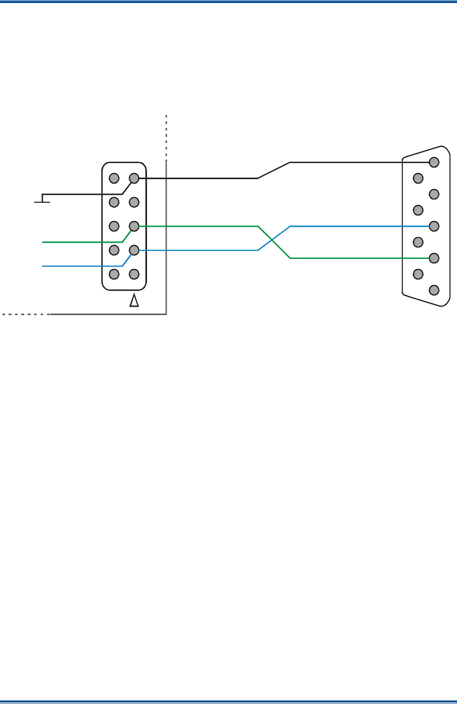
SGD-SB2025NT-TUM, Part 1
Jan 12 Page 75 APPENDIX C
APPENDIX C
CONFIGURATION PROCEDURE CABLE REQUIREMENTS
T36
M
ODULE
S
ERIAL
C
ABLE
The details of the cable required to connect the PC to the pin header HDR1 on the T36 Module in
the SB2025 base station are shown below in Figure C-1.
Figure C-1. T36 Module Serial Cable – wiring details.
1
6
2
7
3
8
4
9
5
GND
5
10
RSRX
RSTX
HDR1
PC
RS232 DB-9
T36 Option Module
2 1
3
7
9
6
8
4

SGD-SB2025NT-TUM, Part 1
Jan 12 Page 76 APPENDIX C
APPENDIX D
SB2025 MICRO CONTROLLER PCB LINK SETTINGS
The link settings detailed in this Appendix should only be carried out by qualified engineering
personnel.
CAUTION
Electrostatic Discharge Sensitive Devices (ESDS Devices). This equipment
contains ESDS Devices, refer to the Personal Safety and Equipment Safety
pages.
L
INK
S
ETTINGS
For correct operation of the Solar 2 P25 NI in the SB2025 base stations, two separate audio paths
for the Tx Audio and Rx Audio have to be created through the Micro Controller PCB. This is
achieved by adjusting various link and jumper settings on the Micro Controller as detailed below.
For details of the Micro Controller PCB component layout, refer to Section 8 – Drawings. The
location of the links and jumpers detailed below are shown overleaf in Figure D-1.
For details of the functions of the Micro Controller Jumpers, refer to Section 3 – Installation and
Operation.
Tx Audio
This input from Solar 2 NI enters the SB2025 on Pin 13 of CN1 DB15 Line I/O connector.
• JMP8 2-3 IN.
• JMP27 2-3 IN.
• T99 link IN.
Rx Audio
This output to Solar 2 NI leaves the SB2025 on Pin 14 of CN1 DB15 Line I/O connector.
• SKK 1-2 OUT
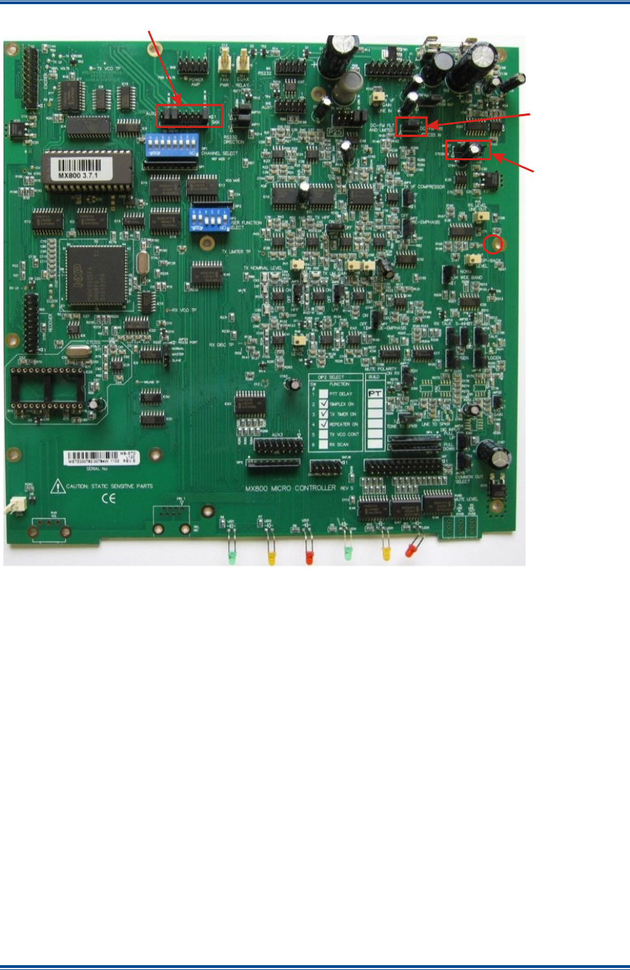
SGD-SB2025NT-TUM, Part 1
Jan 12 Page 77 APPENDIX C
Figure D-1. Micro Controller Jumper and Link locations.
JMP8
JMP27 & T99
SKK
PART 2
ENGINEERING TERMINAL
USER MANUAL

SGD-SB2025NT-TUM, Part 2
Jan 12 Page 3 CONTENTS
PART 2
TABLE OF CONTENTS
Page
Table of Contents (this list) ......................................................................................................... 3
List of Figures .............................................................................................................................. 9
List of Tables .............................................................................................................................. 11
1
INTRODUCTION TO THE ENGINEERING TERMINAL ...................................................... 13
1.1
E
NGINEERING
T
ERMINAL
O
VERVIEW
.................................................................................. 13
1.2
ET
A
PPLICATION
P
ACKAGE
............................................................................................... 13
1.2.1
Traffic Manager ET ................................................................................................ 13
1.2.2
Network Interface ET.............................................................................................. 13
1.3
C
ONNECTING
T
HE
ET
A
PPLICATION
................................................................................... 13
1.3.1
Default Setting........................................................................................................ 14
1.3.2
Com Port................................................................................................................ 14
1.3.3
Making the Connection........................................................................................... 15
1.4
C
LOSING
T
HE
ET.............................................................................................................. 15
1.4.1
Disconnecting the ET ............................................................................................. 15
1.4.2
Exiting the ET......................................................................................................... 16
1.4.3
Accidental Disconnection ....................................................................................... 16
1.5
R
ETAINING
S
OLAR
S
ETTINGS
............................................................................................ 16
1.5.1
Engineering Mode .................................................................................................. 16
1.5.2
Releasing the Engineering Button .......................................................................... 17
1.5.3
Confirming a Change ............................................................................................. 17
2
NETWORK INTERFACE ET ............................................................................................... 19
2.1
I
NTRODUCTION
................................................................................................................. 19
2.2
NI
M
ODE
P
ANEL
............................................................................................................... 20
2.2.1
Eng Area................................................................................................................ 21
2.2.1.1
Manual Trig................................................................................................... 21
2.2.1.2
Test Tone...................................................................................................... 21
2.3
NI
S
TATUS
P
AGE
–
U
PPER
A
REA
....................................................................................... 21
2.3.1
Address.................................................................................................................. 22
2.3.2
Name ..................................................................................................................... 22
2.3.3
Channel.................................................................................................................. 22
2.3.4
Iso I/P and Iso O/P ................................................................................................. 22
2.4
NI
S
TATUS
P
AGE
–
LOWER AREA
....................................................................................... 22
2.4.1
Network.................................................................................................................. 22
2.4.1.1
In/Out............................................................................................................ 22
2.4.1.2
PAT............................................................................................................... 23
2.4.1.3
TOT............................................................................................................... 23
2.4.1.4
Pkt Errors...................................................................................................... 23
2.4.2
PLL ........................................................................................................................ 23
2.4.2.1
Status and Freq Error/Phase Error................................................................ 23
2.4.2.2
Ref ................................................................................................................ 24
2.4.2.3
Offset ............................................................................................................ 24

SGD-SB2025NT-TUM, Part 2
Jan 12 Page 4 CONTENTS
2.4.2.4
DSP .............................................................................................................. 24
2.4.2.5
DAC .............................................................................................................. 24
2.4.3
Timing – PPS ......................................................................................................... 24
2.5
E
NVIRONMENT
I/O
I
NTERFACE
........................................................................................... 24
2.5.1
Environment Status................................................................................................ 24
2.5.2
Indicators ............................................................................................................... 25
2.6
NI
B
UTTON
A
REA
............................................................................................................. 25
2.6.1
Network.................................................................................................................. 25
2.6.2
Eng (Engineering) .................................................................................................. 25
2.6.3
DSP ....................................................................................................................... 25
2.6.4
GPS ....................................................................................................................... 25
3
TRAFFIC MANAGER ET..................................................................................................... 27
3.1
I
NTRODUCTION
................................................................................................................. 27
3.2
M
AIN
W
INDOW
.................................................................................................................. 27
3.3
U
PPER
A
REA
.................................................................................................................... 28
3.3.1
Station NI Panels ................................................................................................... 28
3.4
L
OWER
A
REA
................................................................................................................... 29
3.4.1
TM Status Panel..................................................................................................... 29
3.4.1.1
Duplication .................................................................................................... 29
3.4.1.2
Timing ........................................................................................................... 29
3.4.1.3
Facility Key.................................................................................................... 30
3.4.1.4
Network......................................................................................................... 30
3.4.1.5
Eng ............................................................................................................... 30
3.4.1.6
GPS .............................................................................................................. 30
3.4.1.7
Relations....................................................................................................... 30
3.4.1.8
Logging ......................................................................................................... 30
3.4.1.9
List ................................................................................................................ 30
3.4.1.10
Chan View..................................................................................................... 30
3.4.2
Channel Status Panel............................................................................................. 30
3.4.2.1
Name ............................................................................................................ 31
3.4.2.2
Status............................................................................................................ 31
3.4.3
Central NI Status Panel.......................................................................................... 31
3.4.3.1
Central Indicators.......................................................................................... 31
3.5
R
EMOTE
V
IEW OF A
NI ...................................................................................................... 32
4
SOLAR CONFIGURATION ................................................................................................. 33
4.1
IP
A
DDRESSES
................................................................................................................. 33
4.2
S
ETTING
T
HE
NI
IP
A
DDRESS
(NI
ET
O
NLY
)....................................................................... 33
4.3
S
ETTING
T
HE
TM
IP
A
DDRESS
(TM
ET
O
NLY
).................................................................... 34
4.3.1
Network Connected ET .......................................................................................... 35
4.4
TM
A
DDRESS
I
NVENTORY
................................................................................................. 36
4.4.1
TM Capacity........................................................................................................... 36
4.4.2
Allocating NI........................................................................................................... 36
4.4.3
Allocating a Station NI............................................................................................ 36
4.4.4
Allocating a Central NI............................................................................................ 38
4.4.5
Channel Designation (Multi-channel TM Option) .................................................... 39
5
SOLAR COMMISSIONING.................................................................................................. 40
5.1
C
OMMISSIONING
O
VERVIEW
.............................................................................................. 40
5.2
NI
E
NGINEERING
............................................................................................................... 40

SGD-SB2025NT-TUM, Part 2
Jan 12 Page 5 CONTENTS
5.2.1
Main Audio ............................................................................................................. 40
5.2.1.1
In Audio Sensitivity........................................................................................ 41
5.2.1.2
Audio Input Setup Process............................................................................ 42
5.2.1.3
Out Audio Level ............................................................................................ 43
5.2.1.4
Audio Output Setup Process ......................................................................... 43
5.2.1.5
In Route ........................................................................................................ 44
5.2.1.6
Out Route ..................................................................................................... 44
5.2.1.7
Offset ............................................................................................................ 45
5.2.1.8
LF Talk Thru.................................................................................................. 45
5.2.1.9
Audio Mode (P25 only).................................................................................. 45
5.2.2
Signalling ............................................................................................................... 45
5.2.2.1
Signalling In .................................................................................................. 46
5.2.2.1.1
Voltage................................................................................................... 46
5.2.2.1.2
Signalling Status .................................................................................... 47
5.2.2.2
Signalling Out................................................................................................ 47
5.2.2.3
Manual Trigger.............................................................................................. 48
5.2.2.4
Isolated Inputs............................................................................................... 48
5.2.2.5
Isolated Outputs............................................................................................ 50
5.2.3
Facilities................................................................................................................. 51
5.2.3.1
Name ............................................................................................................ 52
5.2.3.2
GPS Module.................................................................................................. 52
5.2.3.3
Test Tone...................................................................................................... 52
5.2.3.3.1
Level ...................................................................................................... 52
5.2.3.3.2
Frequency .............................................................................................. 52
5.2.3.3.3
Route ..................................................................................................... 53
5.2.3.4
CTCSS Tone................................................................................................. 53
5.2.4
Environment........................................................................................................... 54
5.2.4.1
Status............................................................................................................ 55
5.2.4.2
Mode............................................................................................................. 55
5.3
TM
E
NGINEERING
(TM
ET
O
NLY
) ...................................................................................... 56
5.3.1
Sync Timing ........................................................................................................... 56
5.3.1.1
PAT Reports ................................................................................................. 57
5.3.1.2
Initial Values.................................................................................................. 58
5.3.2
Facilities................................................................................................................. 58
5.3.2.1
Name ............................................................................................................ 59
5.3.2.2
GPS Module.................................................................................................. 59
5.3.2.3
Misc Alarms .................................................................................................. 59
5.3.2.4
SNMP ........................................................................................................... 59
5.3.3
Environment........................................................................................................... 59
5.4
C
HANNEL
S
ETUP
.............................................................................................................. 60
5.4.1
Name ..................................................................................................................... 60
5.4.2
Voting Facilities...................................................................................................... 60
5.4.2.1
Minimum RSSI Difference............................................................................. 60
5.4.2.2
Voter Override............................................................................................... 60
5.4.2.3
Site Deselection Timer (Minutes) .................................................................. 61
5.4.2.4
TM triggered Talk Through............................................................................ 61
5.4.3
Facilities................................................................................................................. 61
5.4.3.1
Tx Key Hang ................................................................................................. 61
5.4.3.2
CTCSS.......................................................................................................... 61
5.5
C
HANNEL
S
ETUP
P25 ....................................................................................................... 61
5.5.1
Audio Mode............................................................................................................ 62
5.5.2
P25 Channel Settings............................................................................................. 62
6
SOLAR CHANNELS (RELATIONS).................................................................................... 63

SGD-SB2025NT-TUM, Part 2
Jan 12 Page 6 CONTENTS
6.1
M
ULTI
-C
HANNEL
O
VERVIEW
.............................................................................................. 63
6.2
R
ELATIONS
F
UNCTION
...................................................................................................... 63
6.2.1
NI to Channel Association ...................................................................................... 63
6.2.2
Moving a Station to a Different Channel ................................................................. 64
6.2.3
Moving a Central NI to a Different Channel ............................................................ 65
6.2.4
Disabling and Re-enabling a NI.............................................................................. 65
6.3
L
IST
................................................................................................................................. 66
7
SOLAR (SYNC) TIMING...................................................................................................... 68
7.1
G
ENERAL
......................................................................................................................... 68
7.1.1
Synchronising Signals............................................................................................ 68
7.1.2
Network Jitter ......................................................................................................... 68
7.2
S
OLAR
I
NTERNAL
T
IMING
.................................................................................................. 68
7.2.1
Determining the Timing Values .............................................................................. 68
7.2.2
PAT Reports .......................................................................................................... 68
7.2.3
Solar Buffer Size .................................................................................................... 69
7.3
P
ARAMETER
C
HECKING
T
OOL
........................................................................................... 69
7.4
L
OSS OF
1PPS
T
IMING
...................................................................................................... 69
7.5
T
IMING
D
IAGRAMS
............................................................................................................ 70
7.5.1
Dynamic Diagrams................................................................................................. 70
7.5.2
Operating the Visio Diagrams................................................................................. 70
8
TM DUPLICATION .............................................................................................................. 71
8.1
D
UPLICATION
O
VERVIEW
................................................................................................... 71
8.1.1
TM Resilience ........................................................................................................ 71
8.1.2
Duplication Operation............................................................................................. 71
8.1.3
Changeover Operation........................................................................................... 72
8.2
C
ONFIGURING FOR
D
UPLICATION
....................................................................................... 72
8.2.1
Unduplicated .......................................................................................................... 72
8.2.2
Duplicated (Primary)............................................................................................... 72
8.2.3
Duplicated (Secondary).......................................................................................... 73
8.2.4
Duplication Status .................................................................................................. 74
9
DIAGNOSTICS AND OTHER INFORMATION .................................................................... 75
9.1
GPS ................................................................................................................................ 75
9.2
F
ACILITY
K
EY
................................................................................................................... 75
9.3
C
HANNEL
V
IEW
F
ACILITY
.................................................................................................. 76
9.3.1
Normal View........................................................................................................... 76
9.3.2
Channel View......................................................................................................... 76
9.3.3
Selecting Channel View ......................................................................................... 76
9.3.4
Returning to Normal View ...................................................................................... 76
10
RECEIVER VOTING............................................................................................................ 78
10.1
V
OTING
O
VERVIEW
........................................................................................................... 78
10.2
S
IGNAL
Q
UALITY
I
NFORMATION
......................................................................................... 78
10.3
V
OTING
P
ROCESS
............................................................................................................. 78
10.4
V
OTER
C
ONFIGURATION
.................................................................................................... 79
10.4.1
Voting Parameters ................................................................................................. 79
10.5
B
EST
S
IGNAL
S
ELECTION
–
P
ARAMETERS
.......................................................................... 79

SGD-SB2025NT-TUM, Part 2
Jan 12 Page 7 CONTENTS
10.5.1
RSSI ...................................................................................................................... 79
10.6
S
QUELCH
I
NPUT
(COR)..................................................................................................... 80
11
ET TROUBLESHOOTING AND MAINTENANCE ............................................................... 81
11.1
N
ETWORK
L
ATENCY AND
F
AULTS
...................................................................................... 81
11.1.1
Packets Arriving Late ............................................................................................. 81
11.1.2
Network Re-routing ................................................................................................ 81
11.1.3
TM Duplication ....................................................................................................... 81
11.1.3.1
Delay from NI to each TM ............................................................................. 82
11.1.3.2
Network Fault causing TM Changeover ........................................................ 82
11.2
F
IRMWARE
U
P
-I
SSUES
...................................................................................................... 82
11.2.1
Availability .............................................................................................................. 82
11.2.2
Loader – General ................................................................................................... 82
11.2.3
Traffic Manager...................................................................................................... 83
11.2.3.1
Invalid TM firmware....................................................................................... 83
11.2.4
Network Interface ................................................................................................... 84
11.2.5
NI DSP Firmware Up-issue .................................................................................... 84
12
ALARMS ............................................................................................................................. 85
12.1
A
LARMS
O
VERVIEW
.......................................................................................................... 85
12.2
A
LARM
F
UNCTIONALITY
.................................................................................................... 85
12.3
A
LARM
S
ETUP
(TM
ET
O
NLY
) ........................................................................................... 85
12.3.1
Environment Inputs ................................................................................................ 86
12.3.2
Isolated Inputs........................................................................................................ 86
12.3.3
NI Misc Alarms....................................................................................................... 86
12.3.4
TM Misc Alarms ..................................................................................................... 87
12.4
A
LARM
I
NDICATIONS
......................................................................................................... 87
12.4.1
Alarm Active........................................................................................................... 87
12.4.2
Alarm Acknowledge ............................................................................................... 88
12.5
TM
D
UPLICATION
A
LARMS
................................................................................................ 90
12.5.1
Alarms on a Secondary TM .................................................................................... 90
12.5.2
Indicating an Alarm from an Offline TM .................................................................. 90
12.5.3
Secondary TM Alarm Acknowledged...................................................................... 91
13
TM LOGGING...................................................................................................................... 92
13.1
O
VERVIEW
........................................................................................................................ 92
13.2
E
VENT
S
UBJECTS
............................................................................................................. 92
13.2.1
Alarms Log............................................................................................................. 92
13.2.2
System Log ............................................................................................................ 92
13.2.3
Voter Log ............................................................................................................... 93
13.2.4
ET Log ................................................................................................................... 93
13.3
A
CCESS
T
O
T
HE
TM
L
OGS
................................................................................................ 93
13.4
TM
S
YSTEM
T
IME
............................................................................................................. 94
13.4.1
Setting TM System Time ........................................................................................ 94
13.5
L
OG
S
ELECTION
............................................................................................................... 95
13.6
T
RANSFERRING
T
HE
L
OG
.................................................................................................. 95
13.6.1
Saving the Log ....................................................................................................... 96
13.6.2
Log Display ............................................................................................................ 96
13.6.3
Filtering the Log Display......................................................................................... 97

SGD-SB2025NT-TUM, Part 2
Jan 12 Page 8 CONTENTS
13.7
E
VENTS
A
CROSS
M
ULTIPLE
L
OGS
..................................................................................... 99
14
SNMP ................................................................................................................................ 100
14.1
O
VERVIEW
O
F
SNMP
I
N
S
OLAR
...................................................................................... 100
14.2
C
ONFIGURING
SNMP
I
N
T
HE
TM ..................................................................................... 100
14.2.1
SNMP Communities and System ......................................................................... 100
14.2.2
Trap Destinations ................................................................................................. 101
14.3
D
ATA
O
RGANISATION
..................................................................................................... 102
14.3.1
Data Format ......................................................................................................... 102
14.3.2
Network Interfaces (Centrals and Stations) .......................................................... 102
14.3.3
Channels.............................................................................................................. 102
14.3.4
Traffic Manager.................................................................................................... 103
14.3.5
Traps.................................................................................................................... 103
15
FIRMWARE EXTENSIONS ............................................................................................... 104
15.1
F
IRMWARE
E
XTENSIONS
–
O
VERVIEW
.............................................................................. 104
APPENDICES
A SOLAR CONFIGURABLE SETTINGS.

SGD-SB2025NT-TUM, Part 2
Jan 12 Page 9 CONTENTS
LIST OF FIGURES
Page
Figure 1. ET window – Status Bar................................................................................................ 14
Figure 2. ET opening window....................................................................................................... 14
Figure 3. Options Menu................................................................................................................ 14
Figure 4. ET Setup window. ......................................................................................................... 15
Figure 5. Connected sub-window................................................................................................. 16
Figure 6. Disconnected sub-window............................................................................................. 16
Figure 7. Button options............................................................................................................... 18
Figure 8. An Unconfigured NI....................................................................................................... 19
Figure 9(a). Central Mode. ........................................................................................................... 20
Figure 9(b). Station Mode. ........................................................................................................... 20
Figure 10. NI Mode Panel views. ................................................................................................. 21
Figure 11. NI Status Page – Upper Area...................................................................................... 21
Figure 12. NI Status Page – Lower Area...................................................................................... 22
Figure 13. Environment I/O. ......................................................................................................... 25
Figure 14. NI ET Buttons.............................................................................................................. 25
Figure 15. TM Main window. ........................................................................................................ 27
Figure 16. Station NI panels......................................................................................................... 28
Figure 17. TM Status Panel. ........................................................................................................ 29
Figure 18. TM Status Panel for P25 system. ................................................................................ 29
Figure 19. Channel #1 Status Panel............................................................................................. 30
Figure 20. Central NI #1 Status Panel.......................................................................................... 31
Figure 21. Views of NI with a TM ET. ........................................................................................... 32
Figure 22. Setting the NI IP Address. ........................................................................................... 33
Figure 23. Setting the TM IP Address. ......................................................................................... 34
Figure 24. Changing to a Network Connected TM ET. ................................................................. 35
Figure 25. Allocating a Station NI................................................................................................. 37
Figure 26. Station #1 allocated and operating. ............................................................................. 37
Figure 27. Allocating a Central NI. ............................................................................................... 38
Figure 28. Central #1 allocated and operating.............................................................................. 39
Figure 29. NI Engineering – Main Audio (Analogue). ................................................................... 41
Figure 30. NI Engineering – Main Audio (P25). ............................................................................ 41
Figure 31. Audio I/P Level adjustment.......................................................................................... 42
Figure 32. Audio Output Level adjustment. .................................................................................. 43
Figure 33. In Route functions. ...................................................................................................... 44
Figure 34. Out Route functions. ................................................................................................... 44
Figure 35. Offset facility. .............................................................................................................. 45
Figure 36. LF Talk Thru facility..................................................................................................... 45
Figure 37. Audio Mode facility (P25 only)..................................................................................... 45
Figure 38. NI Engineering – Signalling page. ............................................................................... 46
Figure 39. Signalling In – Menu Options. ..................................................................................... 46
Figure 40. Signalling In Configurations......................................................................................... 47
Figure 41. Signalling Tone Output................................................................................................ 48
Figure 42. Isolated Input Options. ................................................................................................ 49

SGD-SB2025NT-TUM, Part 2
Jan 12 Page 10 CONTENTS
Figure 43. Isolated Output Options............................................................................................... 50
Figure 44. NI Engineering – Facilities page.................................................................................. 51
Figure 45. GPS Module Timing Source Menu Options................................................................. 52
Figure 46. Test Tone Facility........................................................................................................ 53
Figure 47. CTCSS Tone level. ..................................................................................................... 54
Figure 48. NI Engineering – Environment page............................................................................ 54
Figure 49. Environment Mode settings......................................................................................... 55
Figure 50. TM Engineering – Sync Timing (Station NIs)............................................................... 56
Figure 51. TM Engineering – Sync Timing (Central NIs). ............................................................. 57
Figure 52. TM Engineering – Facilities page. ............................................................................... 58
Figure 53. TM Engineering – Environment page. ......................................................................... 59
Figure 54. Channel Setup page (Analogue). ................................................................................ 60
Figure 55. Channel Setup page (P25).......................................................................................... 62
Figure 56. Route to Relations page.............................................................................................. 63
Figure 57. Relations Page............................................................................................................ 64
Figure 58. Moving a Station NI between Channels....................................................................... 64
Figure 59. Moving a Central NI between Channels. ..................................................................... 65
Figure 60. Examples of disabled NI.............................................................................................. 66
Figure 61. Route to List facility. .................................................................................................... 66
Figure 62. Pages in the ‘List’ window. .......................................................................................... 67
Figure 63. Setting for Duplicated (Primary). ................................................................................. 73
Figure 64. Setting for Duplicated Secondary. ............................................................................... 73
Figure 65. Duplication Status Indication. ...................................................................................... 74
Figure 66. Satellite Signal Report................................................................................................. 75
Figure 67. GPS Options menu. .................................................................................................... 75
Figure 68. Facility Key information. .............................................................................................. 76
Figure 69. Examples of Channel View Mode................................................................................ 77
Figure 70. Loader Application. ..................................................................................................... 83
Figure 71. NI DSP Upgrade. ........................................................................................................ 84
Figure 72. Setting Alarms for Environment Inputs on a NI............................................................ 86
Figure 73. Setting Alarms for Isolated Inputs on a NI. .................................................................. 86
Figure 74. Setting Misc Alarms for a NI........................................................................................ 87
Figure 75. Alarms Setup for a TM. ............................................................................................... 87
Figure 76. Examples of Alarm Indications. ................................................................................... 88
Figure 77. PPS Alarm on the TM. ................................................................................................ 89
Figure 78. Alarm on the NI Signalling page.................................................................................. 89
Figure 79. Alarm on the NI Environment page. ............................................................................ 90
Figure 80. Route to TM Logging................................................................................................... 93
Figure 81. The TM Logging window. ............................................................................................ 94
Figure 82. Selecting an Alarm Log. .............................................................................................. 95
Figure 83. Transferring a Log File to the ET................................................................................. 96
Figure 84. Saving a Log File. ....................................................................................................... 96
Figure 85. Example of a System Log. .......................................................................................... 97
Figure 86. Applying a Display Filter.............................................................................................. 98
Figure 87. Filtering the Log Display on ‘Channel’. ........................................................................ 98
Figure 88. Filtering the Log Display on ‘Type’. ............................................................................. 98

SGD-SB2025NT-TUM, Part 2
Jan 12 Page 11 CONTENTS
Figure 89. SNMP Text Label/Data Entry. ................................................................................... 101
Figure 90. SNMP Trap Address Entry. ....................................................................................... 101
LIST OF TABLES
Page
Table 1. Isolated I/P Functions..................................................................................................... 49
Table 2. Isolated O/P Functions in ‘Auto’ mode............................................................................ 51
Table 3. NI Timing Signal Options................................................................................................ 52
Table 4. Voter Adjustable Parameters.......................................................................................... 79
Table 5. RSSI Requirements........................................................................................................ 79
Table 6. SNMP Data Format for NI Info. .................................................................................... 102
Table 7. SNMP Data Format for Channel Info............................................................................ 102
Table 8. SNMP Data Format for TM Info.................................................................................... 103
Table 9. SNMP Data Format for Trap Info.................................................................................. 103
Table 10. Configuration Byte Usage........................................................................................... 104
Table A1. List of ET Settings...................................................................................................... 105

SGD-SB2025NT-TUM, Part 2
Jan 12 Page 12 CONTENTS
Intentionally left blank.

SGD-SB2025NT-TUM, Part 2
Jan 12 Page 13 INTRO TO ET
1 INTRODUCTION TO THE ENGINEERING TERMINAL
1.1 E
NGINEERING
T
ERMINAL
O
VERVIEW
In the context of engineering, the ET is the primary source for control and monitoring of a Solar
Network for both Analogue and P25 systems. It must be stressed that the ET is not designed for
use by a control operator; a bespoke supervisory application or Simple Network Management
Protocol (SNMP) is best suited for that task.
Basic connection of the ET is to the front panel USB (Type B) connector. The Solar 2 unit uses a
four port USB interface module and, on connection to the PC, four new ports will become available
on the PC. Of these, only three ports can be ever be used as each of the main internal modules is
connected to one of the ports when fitted; i.e. one port is reserved for the TM and two ports are
reserved for each of the NI.
The TM also supports a network connected ET, which allows remote diagnostics and monitoring
(subject to network permissions), however, the initial TM configuration can only be made with a
locally connected ET.
1.2 ET
A
PPLICATION
P
ACKAGE
A common software application package services all hardware builds of Solar 2 units. The
software application will automatically determine the type of module to which it connects and
present the corresponding status window for that module; i.e. a TM or a NI. The software
application package is available as zipped downloads from the web site at
http://www.teamsimoco.com/downloads. This is an executable file that operates under the
Windows™ operating system. It does not require an installation process and may be copied freely
but remain the intellectual property of Simoco.
Whilst the ET software application is a single, common package, the TM ET and NI ET effectively
operate as two separate independent entities and, for the sake of clarity, will be treated as such in
this manual. If the user needs to connect to two units of either type at the same time this is
perfectly legitimate but requires that two instances of the software are run at the same time.
This can be achieved by making a second copy of the software and placing it in a different folder
(directory) on the PC to the first copy. This is necessary so that each copy can keep its own
configuration (ini) file, which contains the default settings that will be used by that instance of the
software and allows the folders to be suitably named to help minimise any confusion.
1.2.1 Traffic Manager ET
The TM ET software provides both system monitoring and access to the system configuration
parameters. Engineering control of every NI is an inherent feature and being able to remotely
access the system through the TM ET is a major benefit.
1.2.2 Network Interface ET
The NI ET software services NIs operating in both Central and Station mode. The style of
presentation is different for the Central and Station functions; there is also a style for units that are
not assigned (not yet configured) as either. The style to be used with a particular NI will be picked-
up automatically.
1.3 C
ONNECTING
T
HE
ET
A
PPLICATION
When the ET application is started, an opening window will appear as shown in Figure 2 overleaf.
At the bottom of the opening window on the Status Bar, the TX and RX indicators, when they are
lit, show that the serial communications to the PC is active. Also displayed on the Status Bar is the
ET Application part number and version (see Figure 1 overleaf).
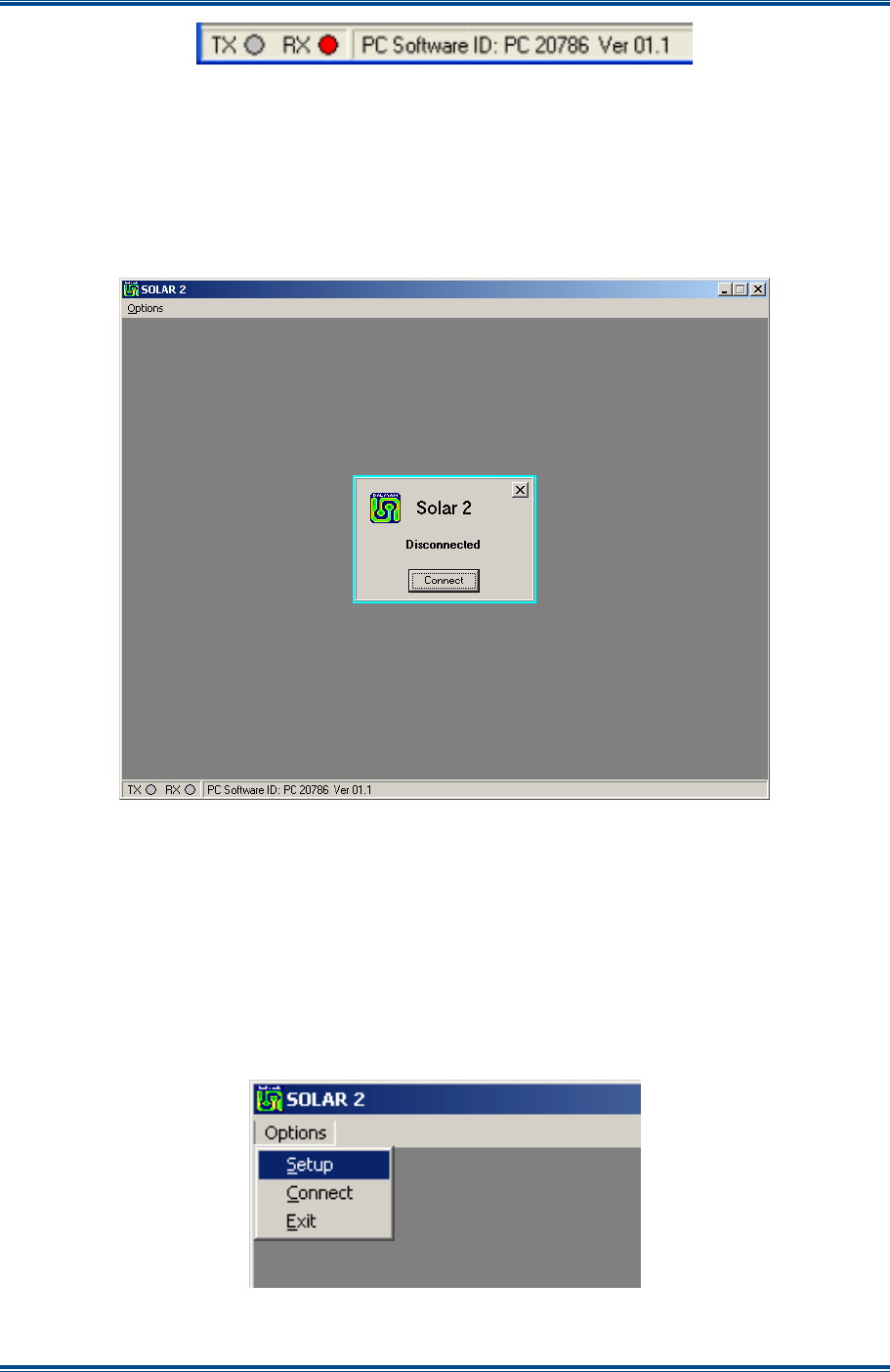
SGD-SB2025NT-TUM, Part 2
Jan 12 Page 14 INTRO TO ET
Figure 1. ET window – Status Bar.
1.3.1 Default Setting
If this is the first usage of an ET application, there will be no default settings, otherwise the settings
will be those used on the last occasion taking information held in an “ini” configuration file. If this
file is not found, it will be automatically created in the same folder as that holding the application
itself. As long as future ET software application releases are placed in that same folder, the
original “ini” file will be recognised and previously selected options will be used.
Figure 2. ET opening window.
1.3.2 Com Port
If there is a need to change the Com port setting, then proceed as follows:
1. On the ET window, carry out the following:
1.1. Close the ‘Disconnected’ sub-window.
1.2. From the menu bar select Options > Setup (see Figure 3 below). The ‘ET Setup’
window will be displayed.
Figure 3. Options Menu.
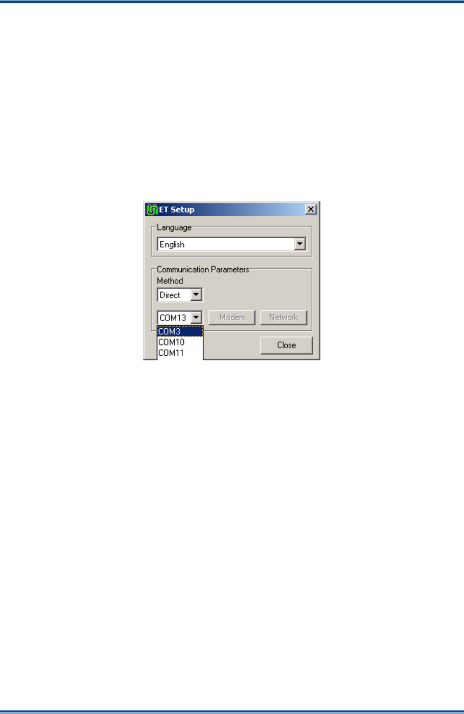
SGD-SB2025NT-TUM, Part 2
Jan 12 Page 15 INTRO TO ET
2. On the ET Setup window (see Figure 4 below), in the ‘Communications Parameters’ area,
carry out the following:
2.1. Using the drop-down list, select the ‘Direct’ Method.
2.2. Using the drop-down list, select the COM Port required.
Note.
Only valid com port numbers will be available.
2.3. Select ‘Close’.
3. On the ET window, from the menu bar, select Options > Connect to return to the original
opening view.
Figure 4. ET Setup window.
1.3.3 Making the Connection
With the PC physically connected to the unit, select ‘Connect’ to establish the data connection
between the ET application and the equipment. The ET will firstly initialise the COM port and then
attempt to connect to the Solar unit, each stage being clearly notified. If the main window display
does not appear and the connection attempt times out after a short period of time, check that the
cable connections are secure and confirm that it is connected to the correct COM port on the PC.
If the ET COM port setting needs to be changed either as a result of a connection failure or the
warning message ‘COM port error’ has been reported, follow the information above to change the
ET COM port settings.
1.4 C
LOSING
T
HE
ET
1.4.1 Disconnecting the ET
To exit the ET, the first task is to “disconnect” the application from equipment; this is a soft (data)
disconnection and not a physical disconnection. The disconnection may be initiated by either
selecting ‘Disconnect’ on the Options menu or clicking on the
(Close) icon on the main window.
Both actions will cause a ‘Connected’ sub-window to appear in the middle of the main window
where confirmation that a disconnect is required (see Figure 5).
SGD-SB2025NT-TUM, Part 2
Jan 12 Page 16 INTRO TO ET
Figure 5. Connected sub-window.
On selecting the ‘Disconnect’ button, the application will terminate the data exchange with the
equipment, the PC Com Port will be released and the window view will return to that which was
seen when the ET was first run showing the ‘Disconnected’ sub-window (see Figure 6).
Figure 6. Disconnected sub-window.
1.4.2 Exiting the ET
To shut down the ET application completely close the ‘Disconnected’ sub-window with the
(Close) icon then either select ‘Exit’ from the Options menu or click on the
(Close) icon on the
ET main window which will now be blank. The ET application will then be terminated.
1.4.3 Accidental Disconnection
If the PC is physically disconnected from the equipment in error by unplugging the serial connector
while the ET is running, the ET will try to re-establish contact with the equipment for approximately
3 seconds. If the connection is restored within that time, the ET will continue as normal. If the
disconnection period exceeds that time, the ET will automatically invoke the disconnection
process. The ‘Disconnected’ sub-window will appear briefly stating ‘No response’ before returning
to the disconnected state.
1.5 R
ETAINING
S
OLAR
S
ETTINGS
All of the NI parameter values and settings are held locally in the NI non-volatile memory as well as
being stored centrally in the TM. The only exception to this is the IP address which is only stored
within the NI itself and cannot be accessed remotely. Changes made to any NI “Engineering”
setting are automatically saved to both the NI and the TM irrespective of where the change is
initiated.
1.5.1 Engineering Mode
Before any engineering changes may be attempted, it is necessary to deliberately select the ‘Eng’
button, furthermore, any change will not be invoked until the ‘Apply’ button is pressed. Multiple
changes may be made and implemented together with a single ‘Apply’ action. Failure to apply a
change will result in the attempted change being abandoned and settings will revert to their
previous state when the corresponding ‘Eng’ button is released.

SGD-SB2025NT-TUM, Part 2
Jan 12 Page 17 INTRO TO ET
1.5.2 Releasing the Engineering Button
It should be noted that failing to release the ‘Eng’ button on either the NI or the TM ET will result in
any incomplete changes (those not applied) being held in the ET memory, therefore, subsequently
applying another change even on a different page will automatically invoke incomplete changes as
well. This is also true if a “new” NI has now got the focus of the ET. The “old” settings, still held in
memory from previous actions, will be passed to this ‘new’ unit when the ‘Apply’ button is selected.
This may result in unwanted changes occurring giving the impression that settings have changed
on their own. This feature is not a bug but is intended to provide a means of being able to replicate
the settings across many units in a quick and simple manner.
Unless using this feature to program multiple units or make multiple changes to a single unit, it is
advisable to apply changes as they are made and release the ‘Eng’ button before moving off the
page.
1.5.3 Confirming a Change
When a change is made to the NI either through the ET connected directly to the NI or remotely
through the TM ET, the action is not complete until confirmation of the change is received back at
the originator. Until the change is confirmed the state is considered to be pending.
A pending change will normally be completed in a few seconds and the interim button state will not
be very evident for long. However, if a NI is not in communication with the TM, the pending state
will last indefinitely until either communication is re-established or the change is abandoned.
This process is evident by interim colour changes of a button, slider (marker) or text in the following
way:
• Button state – IN or OUT – may show a false indication if ‘Apply’ is pending.
• Colour inside the button shows current state – Yellow = Enabled or ON and Grey = Disabled
or OFF.
• Colour outline shows change progress – Blue = pending and Black = done.
• Slider marker shows change progress – Blue = pending and Grey = done; (completion will
also be indicated by the marker moving to be level with the slider control).
• Text colour shows change progress – Blue = pending and Black = done.
In Figure 7 overleaf, the ‘Env O/P’ controls show that:
• Outputs 1 and 2 are OFF and no change is pending.
• Outputs 3 and 4 are ON and no change is pending.
• Outputs 6 and 7 have been switched from ON to OFF but the change is pending; i.e. not yet
complete.
• Outputs 7 and 8 have been switched from OFF to ON but the change is pending; i.e. not yet
complete.

SGD-SB2025NT-TUM, Part 2
Jan 12 Page 18 INTRO TO ET
Figure 7. Button options.
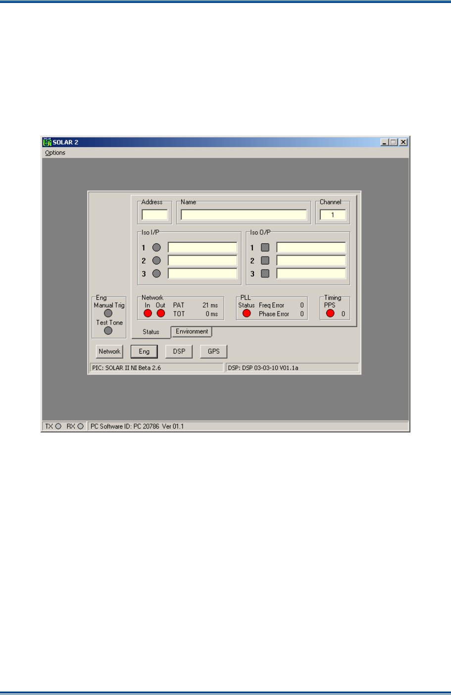
SGD-SB2025NT-TUM, Part 2
Jan 12 Page 19 NI ET
2 NETWORK INTERFACE ET
The screen displays for the NI in this section are those that will be seen when directly connected to
the NI using the front panel USB connection. When accessing an NI remotely through the TM, the
view remains largely the same but only a single ‘Eng’ function is available (see Section 3.5 –
Remote View of an NI).
2.1 I
NTRODUCTION
The initial main window view of an unconfigured and unconnected NI is shown below in Figure 8.
Figure 8. An Unconfigured NI.
Once a basic configuration has been established and the timing and network connections are
made, the main window view will change according to the role assigned to the NI by the TM. This
is reflected in the left hand column or panel where items and facilities related to use are displayed
(see Figures 9(a) and 9(b) overleaf). All of the sub-facilities buttons along the bottom of the
window lead to the same features regardless of the NI mode of operation.

SGD-SB2025NT-TUM, Part 2
Jan 12 Page 20 NI ET
Figure 9(a). Central Mode.
Figure 9(b). Station Mode.
The following sections will outline the meaning of the indications on the NI ET main window. The
purpose of the buttons will be described here but their full usage is covered under other sections.
2.2 NI
M
ODE
P
ANEL
All indications shown in the figures overleaf are shown in an inactive state. A Central NI is shown
in Figure 10a and a Station NI is shown in Figure 10b.
The action of changing the IP address of the NI will cause the unit to return to an unconfigured
state clearing the NI Mode Panel of detail (see Figure 8). Once communications are re-
established with the TM, the NI Mode Panel details will re-appear and show the information relating
to the role of the NI within the Solar network.
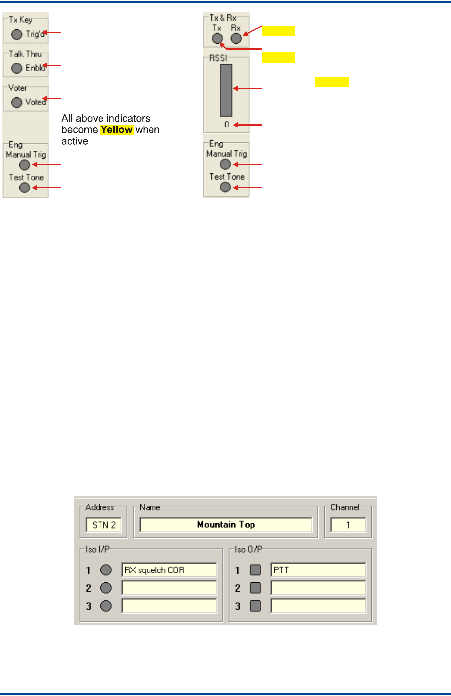
SGD-SB2025NT-TUM, Part 2
Jan 12 Page 21 NI ET
Figure 10. NI Mode Panel views.
2.2.1 Eng Area
2.2.1.1 Manual Trig
This warning indicator is lit Blue when the ‘Manual Trigger’ facility is invoked as this will interfere
with normal operation – see Section 5.2.2.3 – Manual Trigger.
2.2.1.2 Test Tone
Activating the engineering Test Tone (see Section 5.2.3.3 – Test Tone) will cause the ‘Test Tone’
indicator to be lit Blue. This serves as a warning that the NI has been placed in a mode that will
interfere with normal operation.
2.3 NI
S
TATUS
P
AGE
–
U
PPER
A
REA
The default or opening view of the NI is to display the ‘Status’ page as shown in Figure 9. If this
page is not displayed, clicking on the ‘Status’ tab will open the page.
The NI Status page can be divided into the “Upper Area” (see Figure 11 below) and the “Lower
Area”. The upper area comprises of the ‘Address’, ‘Name’, ‘Channel’, ‘Iso I/P’ and ‘Iso O/P’
fields/parameters. The lower area comprises of ‘Network’, ‘PLL’ and ‘Timing’ fields/parameters.
Figure 11. NI Status Page – Upper Area.
Each area and their fields/parameters are now described.
Control/Console operator
initiated transmit function.
Control/Console operator
initiated T/T (repeat)
function.
Incoming (receiving) call
present.
Warning indications of
engineering test facilities
in use. Indications are lit
when active.
Blue
(a)
Rx = Receiver active:
= Active; flashing = Inhibited.
Yellow Red
Tx = Transmitter PTT:
= Active; flashing = Inhibited.
Yellow Red
RSSI level: rising bar for normal
RSSI; full height bar = “Eng Call”
Yellow
Blue
RSSI Value: 0 = no signal; 14 = top
RSSI; 15 = “ Eng Call”
Warning indications of
engineering test facilities
in use. Indications are lit
when active.
Blue
(b)

SGD-SB2025NT-TUM, Part 2
Jan 12 Page 22
NI ET
2.3.1 Address
This indicates the role of the NI in the context of the Solar network. It is not manually entered as it
is derived automatically when the NI is allocated to a role by the TM during the TM configuration
process.
The prefix ‘CEN’ indicates that the mode is “Central” and the prefix ‘STN’ indicates the mode is
“Station”. The suffix indicates the operating number that this unit has been assigned; for Central
the number is in the range of 1 to 16, for Stations 1 to 32.
2.3.2 Name
This is a user defined text label to aid identification of the NI. The name will be displayed in some
of the TM ET windows to assist the user by confirming that the NI being viewed or altered is the
correct one. The process to enter text for the name is detailed in
Section 5.2.3.1 – Name
.
2.3.3 Channel
This shows the current channel assignment of the NI in the multi-channel versions of TM. For
single channel versions this will always be 1.
2.3.4 Iso I/P and Iso O/P
The application of an input condition to an ‘Iso I/P’ (Isolated Input) or activation of an ‘Iso O/P’
(Isolated Output) will be shown by the associated indicator being lit
Yellow
. Each input and output
can be named by the user to aid identification of the role assigned to each function.
For further information on the setup options for these inputs and outputs, see
Section 5.2.2.4 –
Isolated Inputs and Section 5.2.2.5 – Isolated Outputs
respectively. Any Isolated I/P may be
assigned to “Alarm” status – see
Section 12 – Alarms
.
2.4 NI
S
TATUS
P
AGE
–
LOWER AREA
The information in the Network and PLL areas rotate to show the full set of details; the Network
area taking two rotations and the PLL area three rotations as shown below in
Figure 12
.
Figure 12. NI Status Page – Lower Area.
2.4.1 Network
2.4.1.1 In/Out
The ‘Network’ ‘In/Out’ indications are designed to show if data flow fails in either direction, with the
indications turning
Red
if data flow is lost. However, the way in which IP networks operate mean
that one way data flow is an unlikely condition. Clearly, the NI will be aware when the incoming
data fails, however, knowledge that packets are being received by the TM is made evident to the
NI by information in the packets sent from the TM.

SGD-SB2025NT-TUM, Part 2
Jan 12 Page 23
NI ET
Moving the mouse pointer over the ‘In’ indicator will show information about packet errors – see
Section 2.4.1.4
below.
A network failure may be assigned to ‘Alarm’ status – see
Section 12 – Alarms
. There will be a
delay of several seconds between the moment of network failure and the failed indication
appearing, in order to prevent short drop-outs from raising the alarm.
2.4.1.2 PAT
The Packet Arrival Time (‘PAT’) is the time, in milliseconds, taken for packet zero to arrive at the
NI. The value is rounded up to the nearest millisecond and is used as an indication of network
transit time. It is updated every second and is also presented on the ‘Sync Timing’ screen of the
TM ET (see
Section 5.3.1 – Sync Timing
).
This value should largely remain static unless a network re-route is experienced. A figure that is
not stable may indicate a network problem as long as the NI is receiving a valid timing signal. If
the ‘PLL’ is indicating a frequency error, the PAT report cannot be trusted.
2.4.1.3 TOT
This is the setting of the Total Output Time (TOT) as configured in the TM. See
Section 7 – Solar
(Sync) Timing
for detailed information.
2.4.1.4 Pkt Errors
This is an incrementing count updated in real time that shows the number of packets that arrive too
late for processing at the NI (this includes any that do not arrive at all). The value shown is that
which has occurred since the ET was first connected and this may be set to zero by clicking on the
count value.
A total count of packet errors is maintained in the NI itself and this value, together with the ET
value of packet errors, will be displayed in a “hints window” for a short time if the mouse pointer is
positioned over the Network ‘In’ indicator. The NI total count value will be reset by a power off/on
cycle of the NI.
In both cases, the values will roll back to zero after reaching 65,535. A count that is gradually
incrementing indicates that the packets are either being lost or, more likely, arriving close to the
limit of the buffer/time settings, with some simply falling past the boundary.
2.4.2 PLL
2.4.2.1 Status and Freq Error/Phase Error
The ‘PLL’ is the report on the accuracy of the internal clock, which is locked to the 1PPS timing
signal in order to synchronise the audio. At power-up, this indication will be
Red
and the ‘Freq
Error’ and ‘Phase Error’ counts will be zero. Once the PPS timing signal is present, a ‘Freq Error’
will be shown and this will be brought down to zero over a period of several seconds. This will be
followed by a ‘Phase Error’ count being shown, which again will gradually be brought down
towards zero, although this action could take a minute or even longer to achieve. Once the ‘Freq
Error’ count is less than 4 and the ‘Phase Error’ count is less than 30, the ‘Status’ indication will
turn
Green
.
A large PLL error will be manifest as a wideband phase error on the audio output, however, being
a very fine indication, the resultant effect on the audio is such that a ‘Phase Error’ value as high as
50 is most unlikely to be evident in a signal overlap area. A PLL phase error has no discernable
effect for a NI operating in Central mode.

SGD-SB2025NT-TUM, Part 2
Jan 12 Page 24
NI ET
Losing the 1PPS timing signal will cause the frequency and phase error reports to show zero. On
resumption of the timing signal and, depending upon the period of time that the timing signal was
lost, a ‘Freq Error’ may be seen, however, a ‘Phase Error’ is the most likely result together with the
‘Status’ indication being lit
Red
. Errors will be corrected as described above. If the 1PPS timing
signal is lost for a long period, control of the PLL may be taken on by the Traffic Manager – see
Section 2.4.5.2 – Ref
.
A PLL ‘Status’ failure may be assigned to “Alarm” status – see
Section 12 – Alarms
.
2.4.2.2 Ref
The clock reference for the PLL is normally the 1PPS timing signal as indicated by the text report
‘PPS’. Loss of the timing signal will result in a slow drift of the clock and, over an extended period
of time, will result in the timing being too inaccurate and packets will be lost, which will ultimately
cause the NI to cease operating.
In order to mitigate this situation, the TM can assume control of the PLL and adjust the PLL so that
the packet arrival times are maintained. When operating in this mode, the report will show ‘TM
(+x)’ where “x” is a number used by the internal process of frame alignment (normally zero unless
the power has been interrupted). The ‘Freq Error’ and ‘Phase Error’ counts will remain at zero
whilst the PLL is being controlled by the TM.
2.4.2.3 Offset
This is the report of the ‘Offset delay’ that may be applied to each Station NI – see
Section 5.2.1.7
Offset Delay
. Delay offset has no effective meaning or use on a NI operating in Central mode.
2.4.2.4 DSP
This report confirms that the DSP is operating correctly. If a problem occurs the report will show
‘Error’ and the text in the PLL area will no longer rotate.
2.4.2.5 DAC
This is the reading of the internal control of the PLL. The reading will vary during normal operation.
2.4.3 Timing – PPS
A
Green
PPS indication shows that the selected source of 1PPS timing signal (see
Section
5.2.3.2 – GPS Module
) is present; a
Red
indication shows no input. If the timing signal source is a
GPS receiver with NMEA data output, the number shown alongside the indicator is the number of
satellites (Space Vehicles) being used to acquire a fix or the number in use once the fix has been
obtained. Loss of timing signal input may be assigned to “Alarm” status – see
Section 12 –
Alarms
.
2.5 E
NVIRONMENT
I/O
I
NTERFACE
The ‘Environment I/O’ interface is an independent sub-module within the Solar 2 unit. It is
accessible from and available to any of the main modules that are fitted to the unit. Although the
description of the operation of the I/O is presented here under the NI ET it is just the same for the
TM ET if the TM module is installed in the unit. Consequently, any action or setting applied
through one module is visible to and open to change through another module.
2.5.1 Environment Status
The status of each of the sixteen connection points that comprise the ‘Environment I/O’ are
displayed on the Environment page shown in
Figure 13
overleaf. To open this page, select the
‘Environment’ tab.
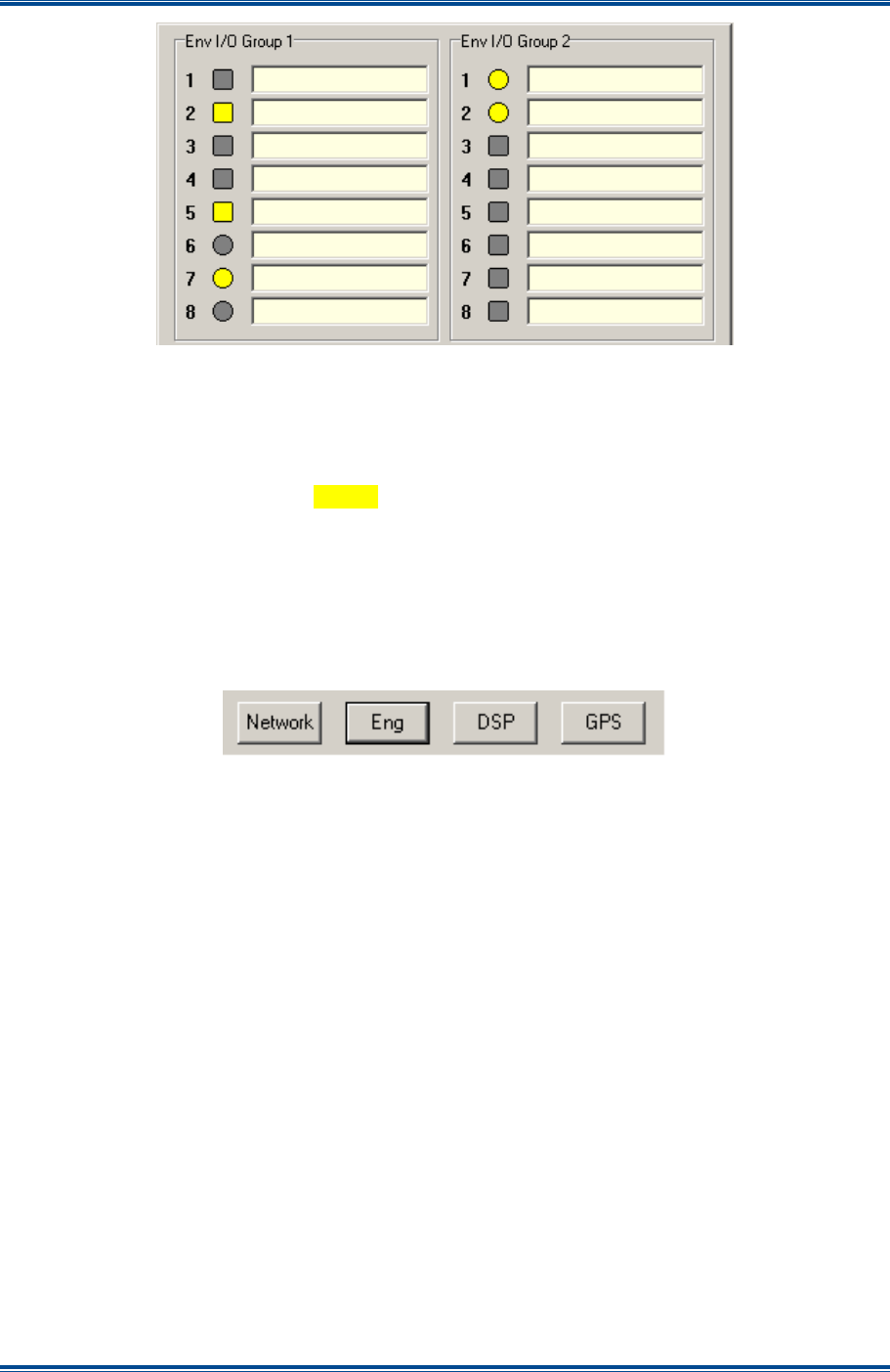
SGD-SB2025NT-TUM, Part 2
Jan 12 Page 25
NI ET
Figure 13. Environment I/O.
2.5.2 Indicators
Each connection point is able to operate as an input or an output, which is defined by the
configuration mode for each connection (see
Section 5.2.4 – Environment
). Inputs are denoted
by a circular indicator and outputs by a square indicator. An active input or output is shown by the
corresponding indicator being lit
Yellow
as seen in
Figure 13
above. Each connection has
provision for a user entered text label alongside the indicator (see
Section 5.2.4.1 – Status
).
2.6 NI
B
UTTON
A
REA
An overview of the functions of each button on the NI ET main page is provided in the sections
below. Full details of the operation of each will be covered under
Section 5 Solar
Commissioning.
Figure 14. NI ET Buttons.
2.6.1 Network
The ‘Network’ button opens the window where the IP address of the NI is entered – see
Section
4.2 – Setting the NI IP Address
for full details. This facility is only available to the NI ET.
2.6.2 Eng (Engineering)
Selecting the ‘Eng’ button opens a new window that has four pages of information: ‘Main Audio’,
‘Signalling’, ‘Facilities’ and ‘Environment’. Each page is accessed by selecting the corresponding
tab – see
Section 5.2 – NI Engineering
for details of each. The results are identical to those
obtained on the TM ET view of the NI.
2.6.3 DSP
The ‘DSP’ button is used if new firmware is to be loaded into the DSP – see
Section 11.2.5 – NI
DSP Firmware Up-issue
for full details. This facility is only available to the NI ET.
2.6.4 GPS
If the 1PPS timing signal is being supplied from a GPS receiver that also has NMEA data output;
e.g. Dalman 60742, the ‘GPS’ button opens a window where information about the satellites and
the received signal levels is displayed. If no NMEA data is available then the window will be
devoid of information.

SGD-SB2025NT-TUM, Part 2
Jan 12 Page 26
NI ET
As the TM also needs a timing signal, the identical facility is available to the TM ET (although not
for a remote view of the NI). Therefore, details of the GPS window and the indicators for both ETs
are given in
Section 9.1 – GPS
.
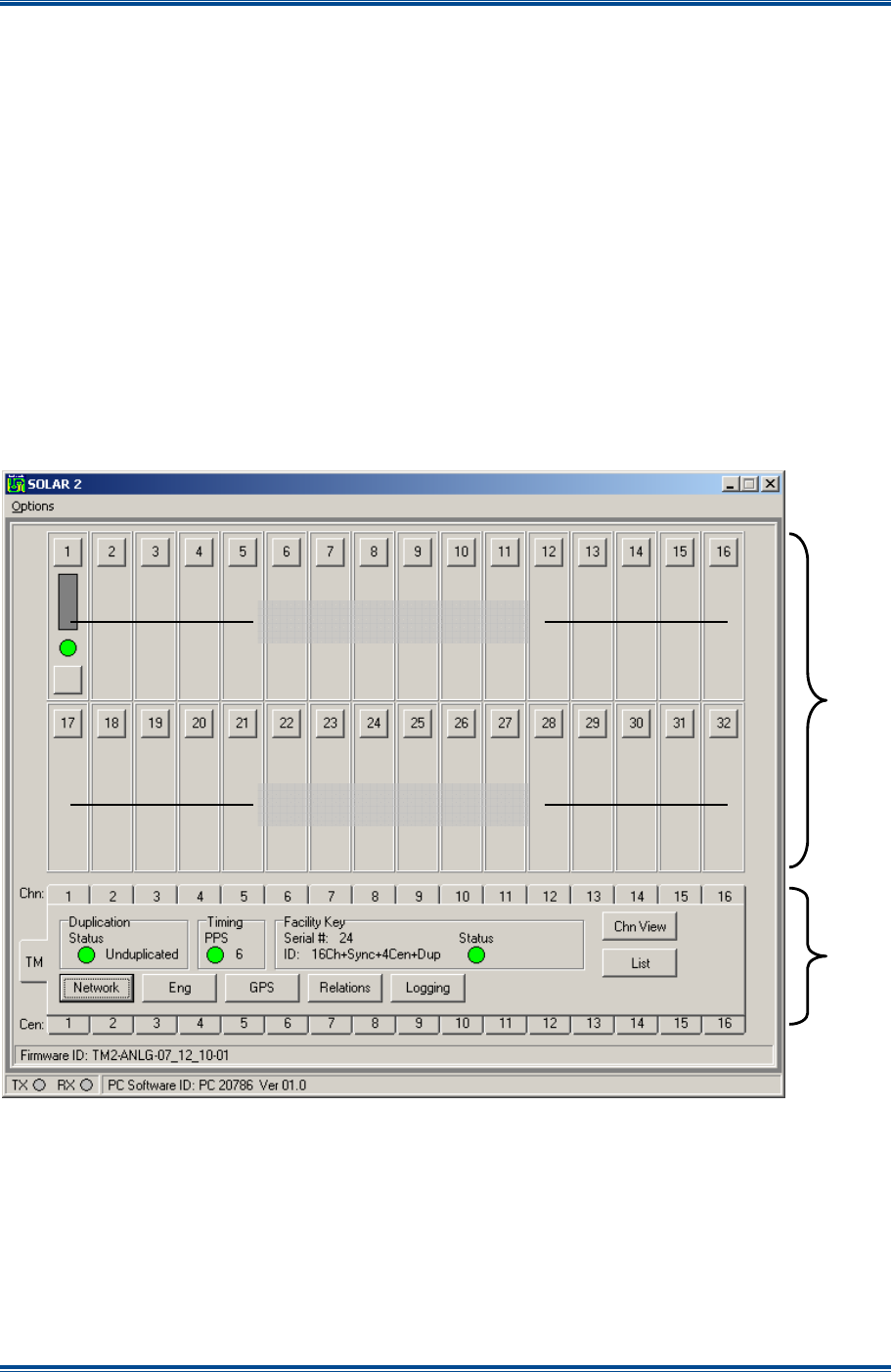
SGD-SB2025NT-TUM, Part 2
Jan 12 Page 27
TM ET
3 TRAFFIC MANAGER ET
3.1 I
NTRODUCTION
The main operating entry level window to the Solar TM ET application software is shown below in
Figure 15
. It provides a reflection of the Solar network status. The Station NI panels will be blank
until assigned an IP address of the respective NI and enabled whereupon additional indicators and
a control become visible.
3.2 M
AIN
W
INDOW
The main window divides into two areas:
• The upper area is fixed and shows the status of all the Station NI.
• The lower area varies according to the selection made.
The example in
Figure 22
below shows a TM that has only been setup for a single station. The
number of channel (‘Chn:’) tabs is likely to be different to this example.
Figure 15. TM Main window.
In
Figure 15
, the Upper Area shows the status of all Stations for all channels through “Station
Interface Panels”. The details in the Lower Area will change to reflect the status of the item
selected.
The following sub-sections and paragraphs outline the meaning of the indications on the main
window and panel areas. Separate sections in this manual deal with the actions and subsequent
pages associated with the buttons.
Station Interface Panels
Station Interface Panels
Upper
area
Lower
area
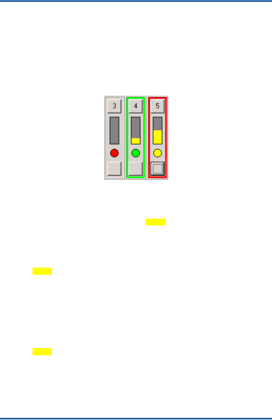
SGD-SB2025NT-TUM, Part 2
Jan 12 Page 28
TM ET
3.3 U
PPER
A
REA
3.3.1 Station NI Panels
As a minimum, each panel in the upper area of the TM ET will have a numbered button displayed.
This button is the route to the IP address assignment facility as shown in
Section 4.4.3 –
Allocating a Station NI
. A second button, a bar and a round coloured indicator will appear once
the panel has been allocated to an NI, i.e. given the IP address of an NI and “Enabled” (see
Figure 16
below).
The panel border highlight is designed to show extra detail about the Station NI and will not appear
until the panel has been allocated.
Figure 16. Station NI panels.
The functions of each indicator are as follows:
• Vertical Bar:
o
RSSI level, indicated by the height of the
Yellow
bar.
o
Voter override, indicated by a
Blue
bar (see
Section 5.4.2.2 – Voter Override
).
• Round Status indicator:
o
Green
– Normal condition during no signal/idle period.
o
Yellow
– Site selected by “voter”.
o
Red
steady – No network comms.
o
Red
flashing – NI inhibit invoked or no timing signal input.
• The panel border highlight colours:
o
No highlight – this station is not in the currently selected channel.
o
Green
– this station is a member of the selected channel.
o
Red
flashing – an alarm is present or has not been acknowledged.
o
Yellow
flashing – an alarm is present and has been acknowledged.
• Bottom button (no legend):
o
Access to the remote view of a Station NI for engineering purposes.
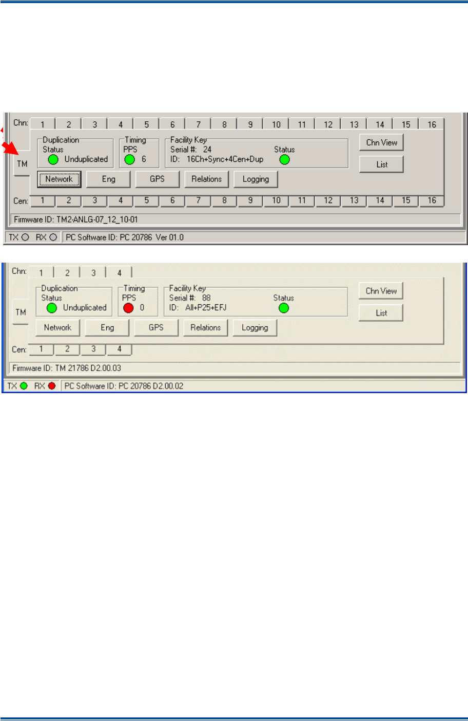
SGD-SB2025NT-TUM, Part 2
Jan 12 Page 29
TM ET
3.4 L
OWER
A
REA
3.4.1 TM Status Panel
The TM Status panel is selected by selecting the ‘TM’ tab (indicated in
Figure 17
below). The
example shown below in
Figure 17
is of a TM with the maximum number of channels enabled; a
typical TM configuration is likely to have many fewer channels. When used with a Solar 2 P25
system, a maximum of four channels can be enabled (see
Figure 18
).
Figure 17. TM Status Panel.
Figure 18. TM Status Panel for P25 system.
The status indications presented on this panel and the configurable settings accessed through the
buttons on this panel are global for the TM, i.e. they are common to all Channels and all NI.
Summary details of each item in this panel are provided in the following sections although the user
may be directed to other sections in this manual for more comprehensive information.
3.4.1.1 Duplication
A normal operating state is indicated by a
Green
status indicator, an abnormal state by a
Red
indicator. See
Section 8.2.4 – Duplication Status
for full details.
3.4.1.2 Timing
A normal operating state is indicated by a
Green
status indicator, an abnormal state by a
Red
indicator. If the timing signal source is a GPS receiver with NMEA data output, the number shown
alongside the indicator is the number of satellites (Space Vehicles) being used to acquire a fix or
the number in use once the fix has been acquired.
Whilst the TM is designed to operate with a global timing signal, it is able to continue operation
without it, since the TM clock timing is not critical to delivering synchronised audio. Under this
situation, the TM will adjust its clock to maintain consistent PAT timing reports from NIs that have
the global timing signal. This is indicated by the text ‘NI’ replacing that of the ‘SV’ number
alongside the indicator which will remain lit
Red
.
Loss of the timing signal may be assigned to “Alarm” status – see
Section 12 – Alarms
.

SGD-SB2025NT-TUM, Part 2
Jan 12 Page 30
TM ET
3.4.1.3 Facility Key
A normal operating state is indicated by the status indicator being lit
Green
, an abnormal state by a
status indicator being lit
Red
. See
Section 9.2 – Facility Key
for full details.
3.4.1.4 Network
See
Section 4.3 – Setting the TM IP Address
for full details.
3.4.1.5 Eng
See
Section 5.3 – TM Engineering
for full details.
3.4.1.6 GPS
See
Section 9.1 – GPS
for full details.
3.4.1.7 Relations
See
Section 6 – Solar Channels (Relations)
for full details.
3.4.1.8 Logging
See
Section 13 – TM Logging
for full details.
3.4.1.9 List
The ‘List’ feature is an aid for the user as opposed to a commissioning tool. It presents the user
with a window giving a list of ‘System Names’, i.e. those given to every NI and channel on the TM.
Whist this is available as a discrete function from the ‘List’ button, it is most useful when the
‘Relations’ function is used and can be accessed directly from that page. It is therefore described
in greater detail in
Section 6 – Solar Channels (Relations)
.
3.4.1.10 Chan View
See
Section 6.3 – Channel View Facility
for full details.
3.4.2 Channel Status Panel
To select the status window for Channel #N (where N is the number of the required channel), click
‘Chn:’ N tab (indicated in
Figure 19
below). The tab will gain a
Green
highlight when selected as
does the Station Interface panels of all member sites of this Channel (see
Section 3.3.1 – Station
NI Panels
). If a Central NI has been assigned to operate this Channel, the tab for that unit will also
gain the
Green
highlight. The example in
Figure 19
shows Channel #1 selected, which is
operated by Central NI #1.
Functions and facilities accessed using the ‘Setup’ button are covered in
Section 5.4 – Channel
Setup
.
Figure 19. Channel #1 Status Panel.
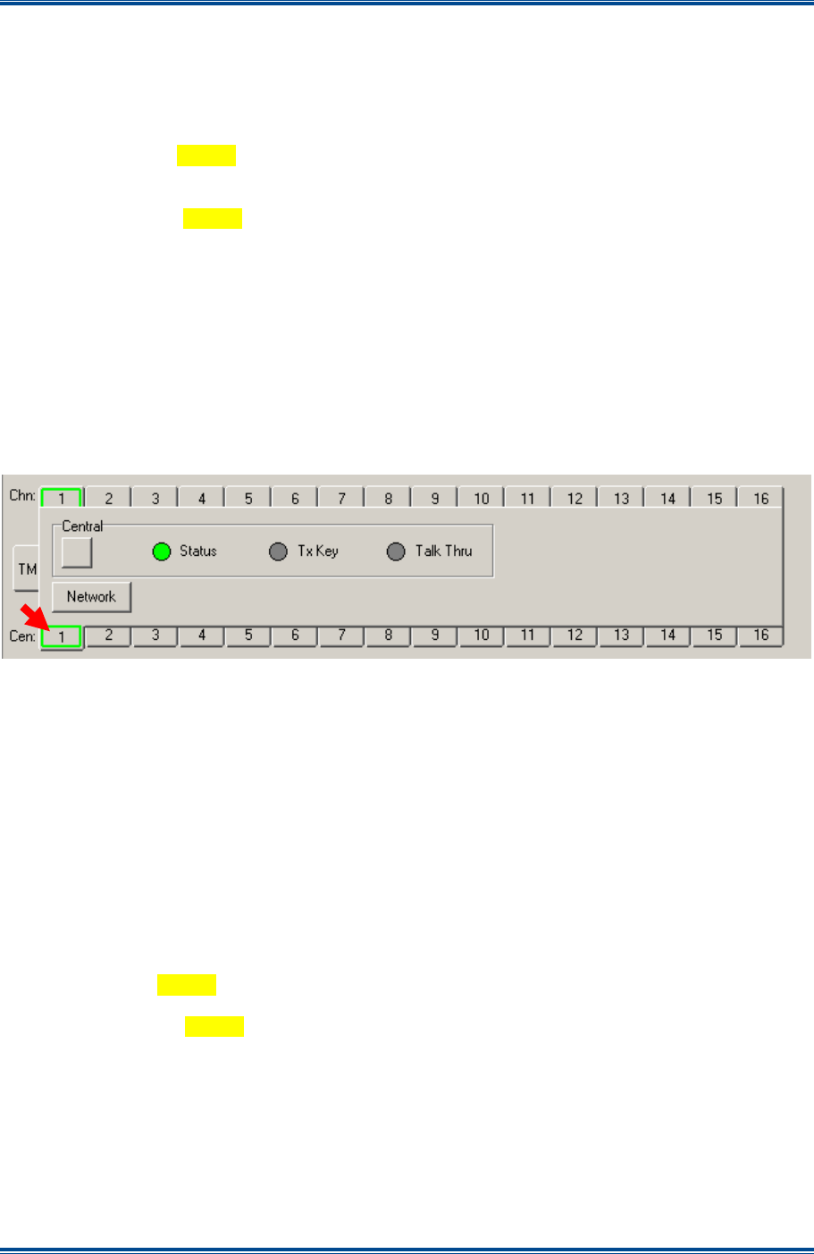
SGD-SB2025NT-TUM, Part 2
Jan 12 Page 31
TM ET
3.4.2.1 Name
A simple text label that can be entered by the user through ‘Setup’ to identify one channel from
another (see
Section 5.4.1 – Name
).
3.4.2.2 Status
(a). ‘
MTx Key
’ – lit
Yellow
when the channel is keyed either by a control PTT from a Central NI
or as a result of a voted signal being present while T/T is on.
(b). ‘
Talk Thru
’ – lit
Yellow
when the channel has T/T switched on either by an input signal to a
Central NI or a setting of the TM Setup.
(c). ‘
Voted Site
’ – the number of the site currently selected as offering the best incoming signal is
displayed. The number is that of the station panel for that site.
(d). ‘
Voted Level
’ – the Solar RSSI level that is being presented by the site currently selected.
3.4.3 Central NI Status Panel
The status window for Central NI #N (where N is the number of the NI) is selected by clicking on
the ‘Cen:’ N tab (highlighted in
Figure 20
below).
Figure 20. Central NI #1 Status Panel.
The Central NI Status Panel tab gains a
Green
highlight when selected as does the Channel ‘Chn:’
#N tab to which the Central NI has been assigned. All the Station Interface Panels that are
members of the Channel will also gain the
Green
highlight. The example in
Figure 20
shows
Central NI #1 selected, which operates Channel #1.
The facility accessed using the Network button is covered in
Section 4.4.4 – Allocating a Central
NI
. The button (no legend) in the ‘Central’ area provides access to the remote view of the Central
NI for engineering purposes.
3.4.3.1 Central Indicators
(a). ‘
Status
’ – lit
Green
when network communications with the Central NI is established and
Red
if it fails. This may be assigned ‘Alarm’ status – see
Section 12 – Alarms
.
(b). ‘
Tx Key
’ – lit
Yellow
when the Central NI has a PTT applied from a control or console input.
(c). ‘
Talk Thru
’ – lit
Yellow
when the Central NI has the T/T input signal applied. The indicator
and text will be disabled (greyed out) if the Central NI is not configured for control of T/T –
see
Figure 28
as an example and
Section 5.2.2.4 – Isolated Inputs
for details on
configuring Isolated Inputs.
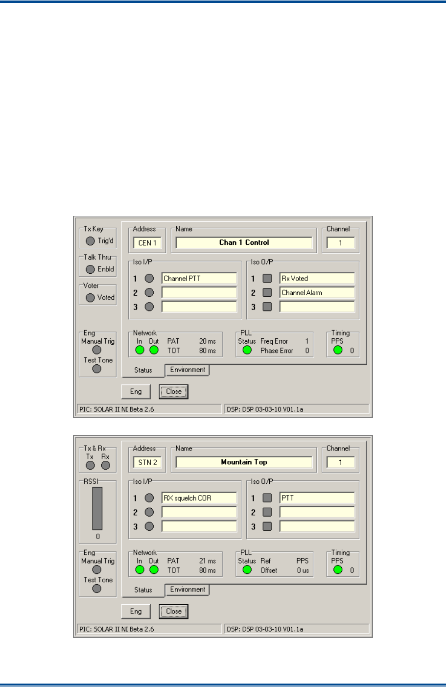
SGD-SB2025NT-TUM, Part 2
Jan 12 Page 32
TM ET
3.5 R
EMOTE
V
IEW OF A
NI
The facility to remotely examine the status and adjust the engineering settings of a NI from a
connection to the TM is enormously beneficial especially if the host network permits this to be
achieved from anywhere on the network. The view of any NI when accessed in this way is
essentially the same as for a local NI ET connection, the main difference being the number and
designation of the buttons across the lower area.
There are two examples of a NI accessed through the TM ET shown overleaf in
Figure 21
; a
Central NI on the top and a Station NI on the bottom (again the outer frame of the ET screen has
been removed for clarity).
The TM ET only shows the ‘Eng’, ‘Alarms’ and ‘Close’ buttons. With the exception of “Alarm”
related items which are only available to the TM ET as alarm functions, the ‘NI Engineering’
facilities accessed through the ‘Eng’ button are identical to that of a locally connected NI ET – refer
to those sections in the handbook as necessary. The ‘Close’ button closes the view of the NI as
does the standard Windows™ close icon
in the top right corner.
Figure 21. Views of NI with a TM ET.
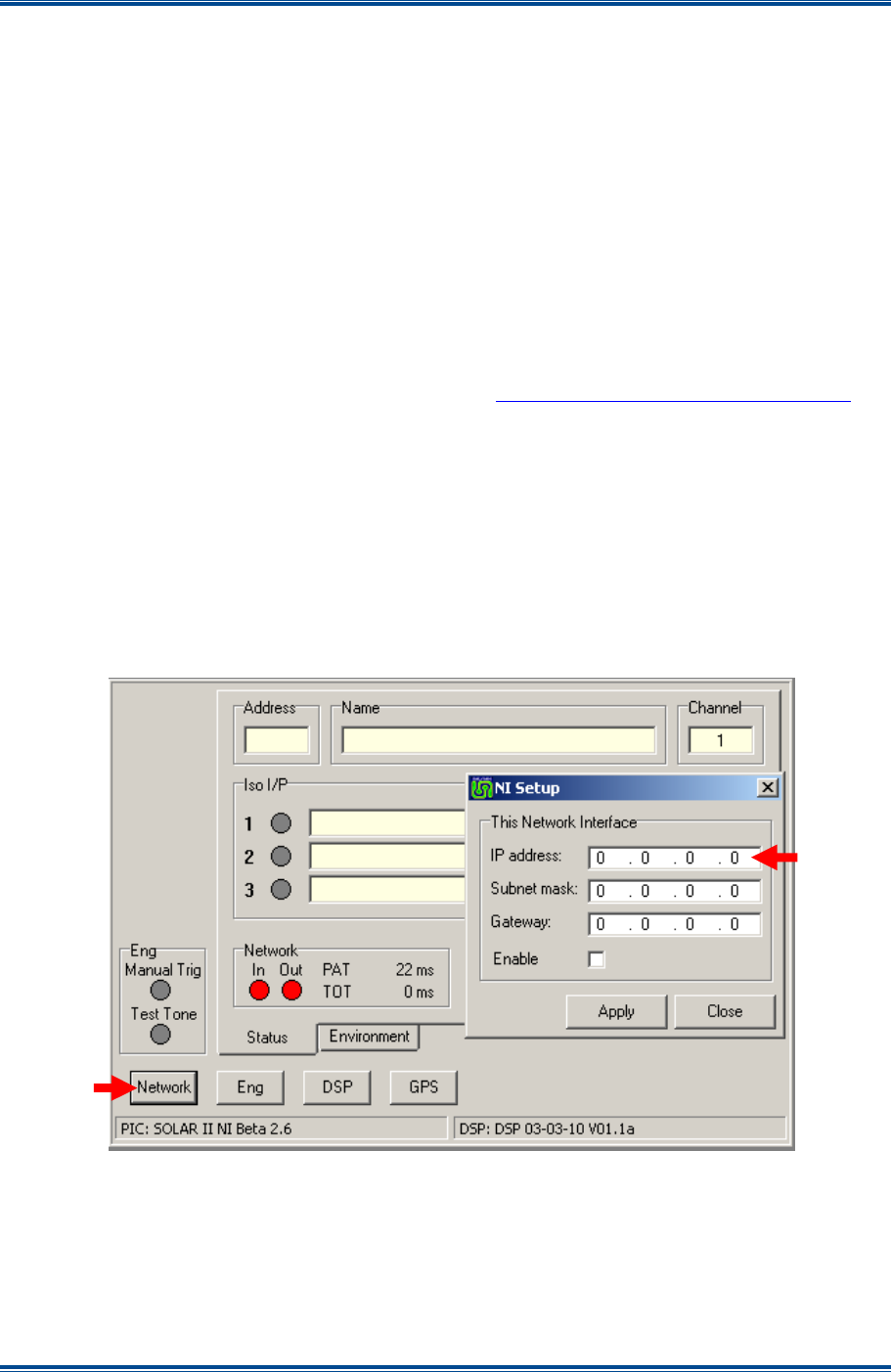
SGD-SB2025NT-TUM, Part 2
Jan 12 Page 33
SOLAR CONFIGURATION
4 SOLAR CONFIGURATION
4.1 IP
A
DDRESSES
For efficient and effective user interaction with the ET, it is essential that the user has knowledge of
the topography of the system.
Before anything else can happen the IP addresses of the equipment must be assigned and set.
The assigned IP address for an individual unit on any monolithic network must be unique, i.e. there
must not be more than one equipment unit with a given IP address. This rule covers all equipment
units on the network and there may be units that have no relationship with the Solar equipment.
Generally, the IP addresses will be assigned by a network administrator – possibly in agreement
with the Solar commissioning technician. A pre-defined plan of IP addresses is likely to make the
task more straightforward and reduce the possibility of errors.
For an overview discussion about IP addresses, Subnet masks, Primary and Secondary gateways
see the paper published on the Team Simoco web site http://www.teamsimoco.com/downloads.
4.2 S
ETTING
T
HE
NI
IP
A
DDRESS
(NI
ET
O
NLY
)
Connect the NI ET to an NI whereupon the ET main window will show as one of three variants:
unconfigured (
Figure 8
); Station mode; or Central mode (
Figure 9
). It is not necessary for the NI
to be connected to the network at this stage.
In the example shown below in
Figure 22
, the blank ‘Address’ window and the blank panel on the
left indicate that this NI has not been in communication with a TM. Even if these are not blank, the
action of changing the IP address will cause that information to be cleared and will remain in that
state until communications with a TM is established.
Figure 22. Setting the NI IP Address.
To set the IP address of an NI, proceed as follows:
1. On the NI window, select the ‘Network’ button (indicated) and the NI IP ‘Setup’ window will
be displayed.
2. On the NI IP ‘Setup’ window, carry out the following:
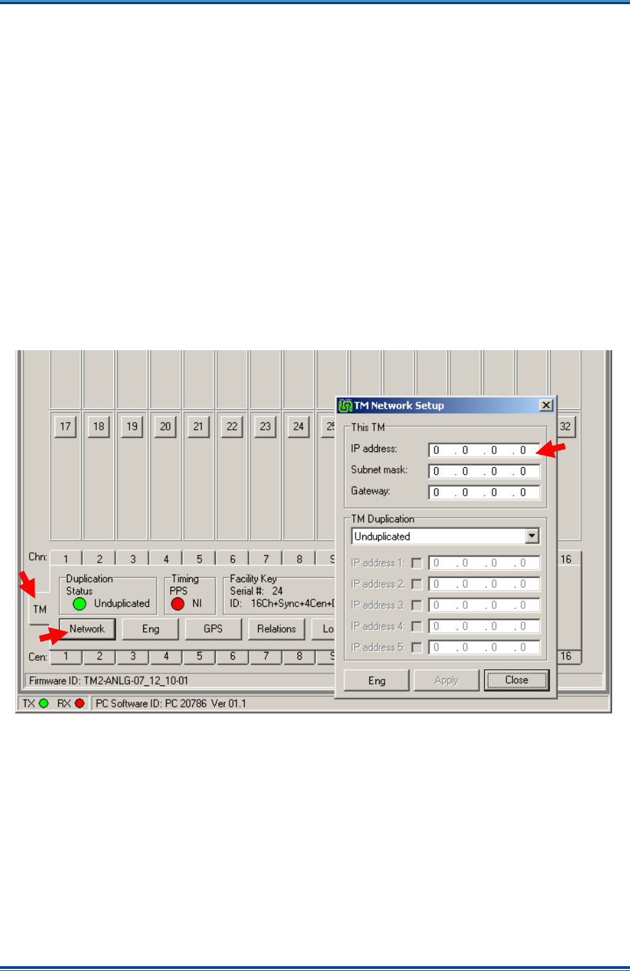
SGD-SB2025NT-TUM, Part 2
Jan 12 Page 34
SOLAR CONFIGURATION
2.1. Enter the IP address and subnet mask.
Note.
The subnet mask and gateway address are not required by a NI but this facility has
been provided for possible future upgrades.
2.2. Check the ‘Enable’ box.
2.3. Select ‘Apply’ and then ‘Close’.
3. Repeat Paras 1 to 2.3 above for every NI in the system.
It may prove helpful if the IP address is noted on the NI case to save having to reconnect the NI ET
later just to find that detail (it is not visible to the TM ET).
4.3 S
ETTING
T
HE
TM
IP
A
DDRESS
(TM
ET
O
NLY
)
The next stage is to set the IP address of the TM and this requires that the TM ET is connected
locally (front panel USB connection).
Figure 23. Setting the TM IP Address.
To set the IP address of a TM, proceed as follows:
1. On the TM ET window, select the ‘TM’ tab (indicated in
Figure 23
) to open the view of the
TM status panel.
2. On the TM Status Panel, select the ‘Network’ button to open the ‘TM Network Setup’ page.
3. On the ‘TM Network Setup’ window, carry out the following:
3.1. Select the ‘Eng’ button and enter the ‘IP address’, ‘Subnet mask’ and ‘Gateway’
address.
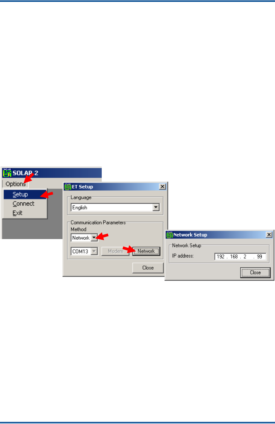
SGD-SB2025NT-TUM, Part 2
Jan 12 Page 35
SOLAR CONFIGURATION
3.2. From the drop-down list, set the ‘Traffic Manager Duplication’ option to ‘Unduplicated’.
(If the duplication option has not been purchased then ‘Unduplicated’ will be the only
available item in the drop-down list).
Note.
Even if the final system configuration is to use the ‘Traffic Manager Duplication’
option, at this stage it should be set as “Unduplicated”. This option can be changed
later as detailed in Section 8 – TM Duplication.
3.3. Select ‘Apply’ then ‘Close’.
4.3.1 Network Connected ET
Once the TM has been given an IP address, it is then possible to continue configuration of the TM
using a network connected ET if this is more convenient.
Note.
A change to the PC IP address may be required in order to put it in the same subnet at
the TM, as the TM does not allocate the address, i.e. it does not provide a Dynamic
Host Configuration Protocol (DHCP) service.
Figure 24. Changing to a Network Connected TM ET.
To change from a local ET to a network connection ET, proceed as follows:
1. Close the existing connection and the ‘Disconnected’ sub-window as per
Section 1.4.1
.
2. On the TM ET window, on the menu bar, select ‘Options’ > ‘Setup’.
3. On the ‘ET Setup’ page, carry out the following:
3.1. From the drop-down list, set the ‘Method:’ to ‘Network’. The ‘Network’ button will now
become active.
3.2. Select the ‘Network’ button and the ‘Network Setup’ page will be displayed.
4. On the ‘Network Setup’ page, enter the ‘IP address’ of the TM and select ‘Close’.
5. On the ‘ET Setup’ page, select ‘Close’.
6. On the TM ET window, on the menu bar, select ‘Options’ > ‘Connect’.

SGD-SB2025NT-TUM, Part 2
Jan 12 Page 36
SOLAR CONFIGURATION
Configuration can now continue as for a local connection. However, it will not be possible to
change any of the IP parameters of the TM itself whilst connected in this way but this information
will be displayed when the TM ‘Network’ button is clicked.
4.4 TM
A
DDRESS
I
NVENTORY
The next stage is to inform the TM of all the NIs that will operate within the Solar network.
Therefore, the IP address of every NI must be known, if not actually programmed into the NI units
although that is preferable.
4.4.1 TM Capacity
A Solar network can be populated by a maximum of 32 NIs operating in Station mode. Depending
upon the configuration options purchased, the Solar P25 network may comprise of multiple
channels up to a maximum of 4 and a maximum of 4 NIs operating in Central mode. One channel
may support the maximum of 32 Station NIs and may be permitted to have more than one Central
NI per channel (this is a factory configured option).
If the PMR system is only required to work in T/T (repeat) mode, a Central NI it is not necessary
(there being no Console or Control Room). Every NI will be assigned a unique system ‘Address’:
Central NIs will range from CEN1 to CEN4; and Stations from STN1 to STN32 – these numbers
are crucial for the multi-channel option.
4.4.2 Allocating NI
It is important to understand that the action of entering the IP address for each and every NI into
the TM’s system address inventory defines the mode of operation of each NI unit within the
system. Furthermore, the settings stored in the TM for the NI relate to the system address and not
to the individual unit’s IP address. It is the system address that is used to allocate stations and
centrals to channels in the multi-channel version.
Whilst the same IP address should not be entered in more than one place in the system, this is not
an illegal action. However, an attempt to ‘Enable’ a second use of the same IP address on the
system will be rejected.
4.4.3 Allocating a Station NI
The upper area of the TM ET main window shows 32 blank station panels, which relate to the 32
possible Station NI (radio base stations) in the Solar network. These will show the status of each
Station NI member as they are connected.
This process would logically start at #1 and increment in order, however, this is not mandatory, as
any Station NI may be assigned to any station panel. For a multi-channel system, there is merit in
arranging the stations in groups with unassigned panels between them, which makes the channel
separation more obvious.
Figure 25
overleaf shows a NI being allocated to Station #1 (station panel #1).
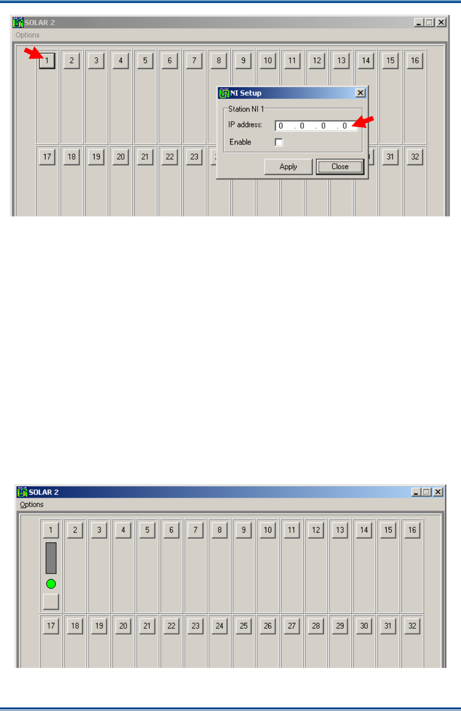
SGD-SB2025NT-TUM, Part 2
Jan 12 Page 37
SOLAR CONFIGURATION
Figure 25. Allocating a Station NI.
The allocation process is as follows:
1. On the TM ET window, on the relevant station panel, click the “identity” button to gain access
to the ‘NI Setup’ page.
2. On the ‘NI Setup’ page, carry out the following:
2.1. Enter the ‘IP address’ of the NI that is to be used as the Station Interface for that
number.
2.2. Check the ‘Enable’ check box.
2.3. Select ‘Apply’ > ‘Close’.
3. Repeat Paras 1 to 2.3 for each Station NI on the system.
If the NI is connected to the network, communication should be established immediately so that the
NI adopts a Station mode of operation with the station panel number displayed as the system
‘Address’ on the NI main window. The station panels will also confirm communication is active by
displaying a
Green
status indication at the bottom of the panel (see
Figure 26
below).
Figure 26. Station #1 allocated and operating.
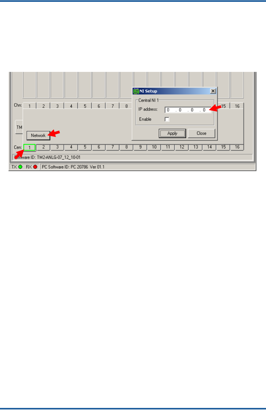
SGD-SB2025NT-TUM, Part 2
Jan 12 Page 38
SOLAR CONFIGURATION
Note.
If an IP address is entered that is the same as one already actively in use anywhere on
the TM this will be cleared back to the previous setting when ‘Apply’ is clicked.
4.4.4 Allocating a Central NI
The process and rules for the allocation of a NI as a Central unit are much the same as for a
Station.
Figure 27. Allocating a Central NI.
The allocation process is as follows:
1. On the TM ET window, open the Central Interface status panel #N by clicking on ‘Cen:’ #N
tab (indicated in
Figure 27
).
2. On the #N Central Interface status panel, select the ‘Network’ button to open the ‘NI Setup’
page.
3. On the ‘NI Setup’ page, carry out the following:
3.1. Enter the ‘IP address’ of the NI that is to be used as the Central Interface for that
number.
3.2. Check the ‘Enable’ check box.
3.3. Select ‘Apply’ > ‘Close’.
4. Repeat Paras 1 to 3.3 for each Central NI on the system.
If the corresponding NI is connected to the network, communication should be established
immediately so the NI will adopt a Central mode of operation and the system Address on the NI
main window will show ‘CEN #N’. The TM central status panel will also confirm communication is
active by displaying a
Green
status indication (see
Figure 28
overleaf).
Note.
If an IP address is entered that is the same as one already actively in use anywhere on
the TM this will be cleared back to the previous setting when ‘Apply’ is clicked.

SGD-SB2025NT-TUM, Part 2
Jan 12 Page 39
SOLAR CONFIGURATION
Figure 28. Central #1 allocated and operating.
4.4.5 Channel Designation (Multi-channel TM Option)
At this stage, every Station NI will be assigned to operate on Channel 1 – this is the default setting.
This does not affect the commissioning process, although it is likely that the task will be conducted
on a channel by channel basis.
Therefore, the user may prefer to go directly to
Section 6 – Solar Channels (Relations)
, which
details the procedures for assigning Station and Central NIs to channels, before proceeding to
Section 5 – Solar Commissioning
.

SGD-SB2025NT-TUM, Part 2
Jan 12 Page 40
SOLAR COMMISSIONING
5 SOLAR COMMISSIONING
5.1 C
OMMISSIONING
O
VERVIEW
Solar commissioning falls into two stages:
(a). Configuring the analogue interface of each NI to suit the requirements of the connected
equipment.
(b). Configuring the system parameters to meet the operational requirements.
Stages (a) lies entirely with the NI and comes under ‘Engineering’ settings, which can be set using
the TM ET as well as the NI ET. Stage (b) lies entirely with the TM and can therefore only be set
using the TM ET.
After the basic commissioning is complete there is likely to be a period of optimisation when the
Solar network is “fine tuned” to the IP bearer network. Ultimately, the user may like to consider
ways to enhance the Solar network with the addition of specific features such as Alarms, SNMP or
TM redundancy (the latter two features are special options). These particular topics are dealt with
in their own sections.
5.2 NI
E
NGINEERING
All “Engineering” settings and adjustments that are accessed under the ‘NI Engineering’ window
are available to both the NI ET and TM ET. The settings are stored in the TM, which continually
sends this information as part of the Solar supervisory system. The settings are also held in the
non-volatile memory of each NI, so that the NI can continue to operate in a fall back mode if
isolated from the TM as well as recovering quickly from a loss of power.
These settings are referenced by the NI ‘Address’ as designated in the TM and not the IP address,
although, naturally, the IP address for each NI must match that held in the TM for correct
operation. This means that replacement of an NI is made much more straightforward as the
‘Engineering’ settings will be automatically uploaded when contact with the TM is established.
For example, replacing the NI in Site #4 will result in the original settings for that site being passed
in a few seconds to the replacement unit, which must match the IP address of the original unit (text
labels will take a lot longer as these are given lowest priority).
The ‘NI Engineering’ window is accessed by clicking on the ‘Eng’ button on the NI main window –
see
Section 2.6 – NI Button Area
. This action opens a new window that has four pages of
information: ‘Main Audio’, ‘Signalling’, ‘Facilities’ and ‘Environment’. Each page is accessed by
clicking on the tab for that page.
The ‘NI Engineering’ window also has an ‘Eng’ button that must be clicked “IN” before a change
can be made, whereupon the ‘Apply’ button will become active. Any changes in settings will not
become active until the ‘Apply’ button is selected. The ‘NI Engineering’ window is closed by
clicking on the ‘Close’ button or the close icon
in the top right hand corner. Any changes made
but not applied will be lost when the window is closed.
If these pages are viewed through the TM ET there will be an ‘Alarm’ button on the lower area of
the page and extra tabs on the ‘Signalling’ and ‘Environment’ pages – see
Section 12 – Alarms
for full details of these functions.
5.2.1 Main Audio
The audio input and output levels and other associated functions are set through this page of the
‘NI Engineering’ facility. The ‘Main Audio’ page of the NI Engineering facility for an Analogue
system is shown overleaf in
Figure 29
.
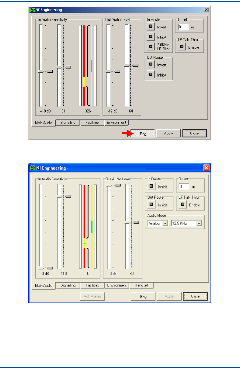
SGD-SB2025NT-TUM, Part 2
Jan 12 Page 41
SOLAR COMMISSIONING
Figure 29. NI Engineering – Main Audio (Analogue).
The ‘Main Audio’ page of the NI Engineering facility for a P25 system is shown below in
Figure 30
.
Figure 30. NI Engineering – Main Audio (P25).
5.2.1.1 In Audio Sensitivity
The input sensitivity is determined by adjustment of a coarse gain setting (left slider) and a fine
gain setting (right slider) (see
Figure 31
). The gauge on the right is an expanded view of the left
hand gauge to provide greater accuracy of setting. The current settings are shown by the marker
to the right of the slider and the numerical value at the bottom.
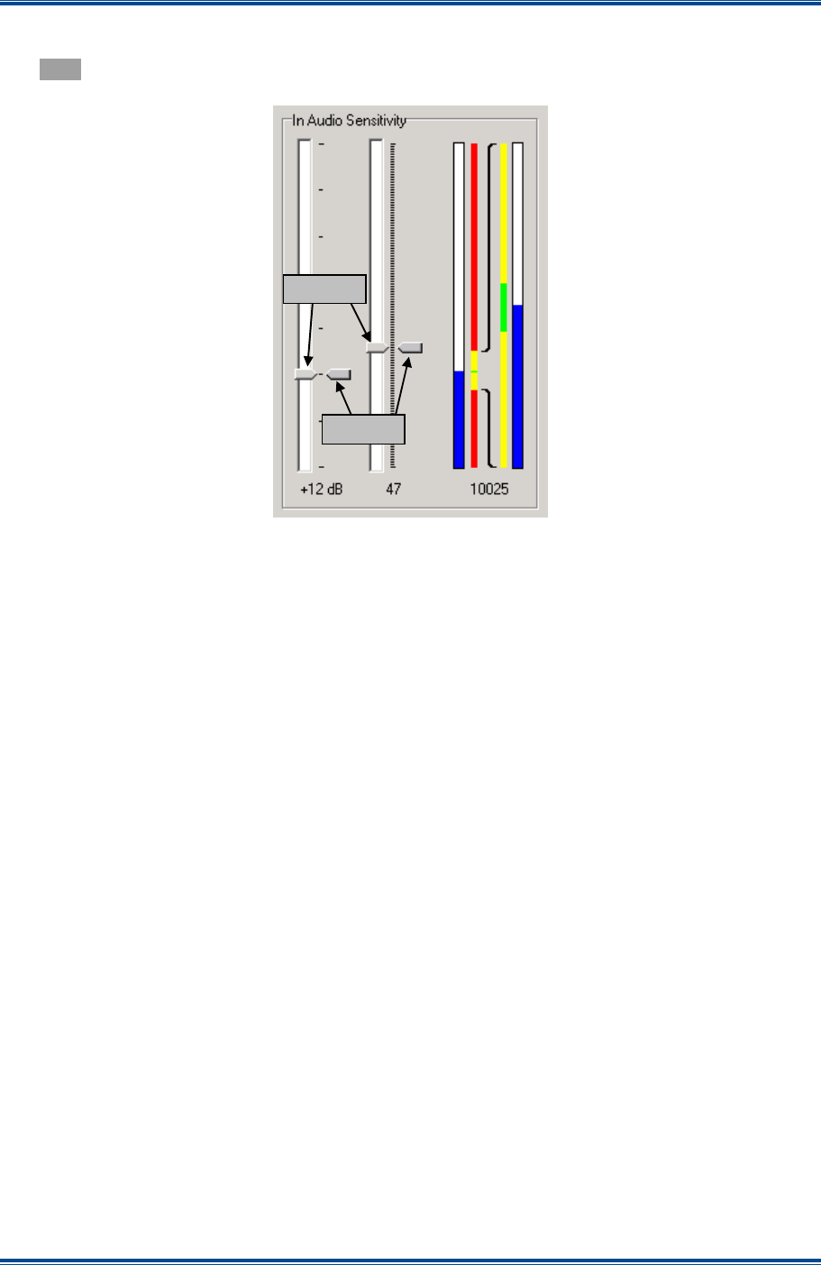
SGD-SB2025NT-TUM, Part 2
Jan 12 Page 42
SOLAR COMMISSIONING
When a level change is applied, the marker alongside the slider will turn
Blue
until the change is
confirmed, whereupon the position of the marker will match that of the slider control pointer and
turn
Grey
again.
Figure 31. Audio I/P Level adjustment.
5.2.1.2 Audio Input Setup Process
The following process is used to setup the audio input sensitivity:
1. Apply a test tone (see note) to the input at the required Peak System Level (PSL).
Note.
Due to the digitisation sampling rate, the gauge and reading will not be stable at a test
tone frequency of 1 kHz or multiples thereof (an aliasing effect). However, even a
small change (a few Hertz) will greatly stabilise the readings. A change of at least
±20 Hz is recommended to give a fully stable result.
2. Adjust the input gain control and fine slider so that the top of the blue “gauge” is aligned to
the centre of the green datum mark. (Adjusting the coarse gain control may cause a
momentary effect on the PLL status).
3. The reading at the foot of the gauge is the Solar internal PSL and a reading of 10,000 (±50)
is the target value.
4. The coarse gain setting steps are 0 db, +6 dB, +12 dB, +18 dB, +20 dB, +26 dB and +32 dB.
5. As a guide, each “click” on the fine slider nominally corresponds to change of 0.05 dB and
changes the internal input level reading by approximately 50 points.
Note.
A change in the coarse gain setting will cause the PLL to show an error and possibly
an alarm for a short duration.
Sliders
Markers
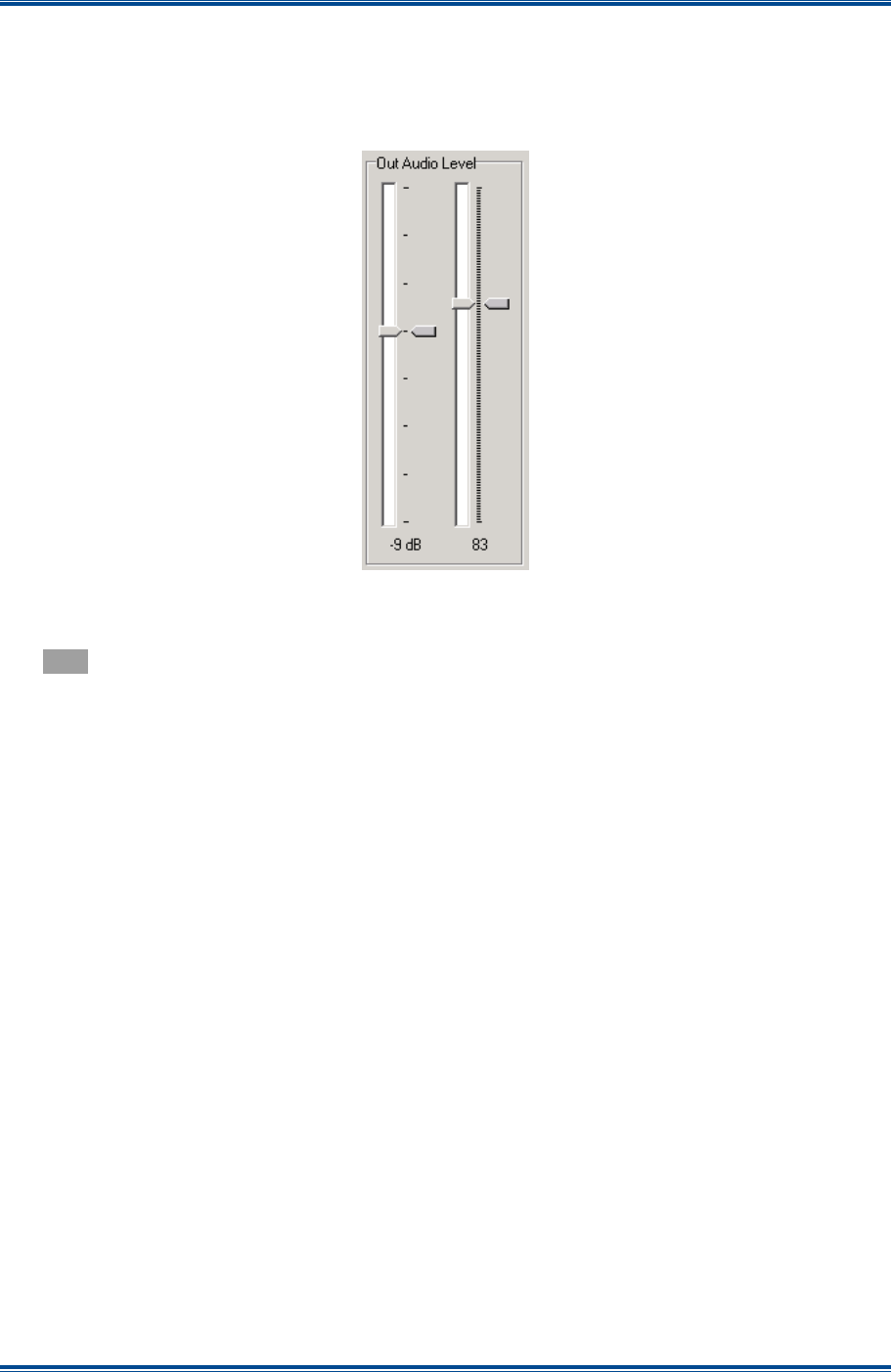
SGD-SB2025NT-TUM, Part 2
Jan 12 Page 43
SOLAR COMMISSIONING
5.2.1.3 Out Audio Level
The audio output level is set using a coarse level control (left slider) and fine level control (right
slider) (see
Figure 32
). The current settings are shown by the marker to the right of the slider and
the value at the bottom.
Figure 32. Audio Output Level adjustment.
When a level change is applied, the marker alongside the slider will turn
Blue
until the change is
confirmed, whereupon the position of the marker will match that of the slider control pointer and
turn
Grey
again.
5.2.1.4 Audio Output Setup Process
The audio output level is set using the Test Tone facility, which is described in more detail in
Section 5.2.3.3 – Test Tone
.
The following process is used to setup the audio output level:
1. Connect an audio level measuring device to the output port ensuring that a 600 Ω termination
is applied.
2. Invoke the internal ‘Test Tone’ to ‘External’ route ensuring that the test tone level is set to
maximum (0 dB).
3. Adjust the output gain control and fine slider to achieve PSL. (Adjusting the coarse gain
control may cause a momentary effect on the PLL status.)
4. The coarse gain settings are in 3 dB steps from 0 dB down to −24 dB
5. The fine slider gives a 6 dB range of control and each “click” nominally corresponds to a
change of 0.05 dB.
Whilst the preferred method is to set peak levels, it is possible to set the audio output for levels
less than peak as long as the Test Tone output level is set to match. For example, to set a 60%
system level of −10 dBm, set the Test Tone output level to −4.4 dB (60% of peak) and adjust the
output level controls to give −10 dBm.
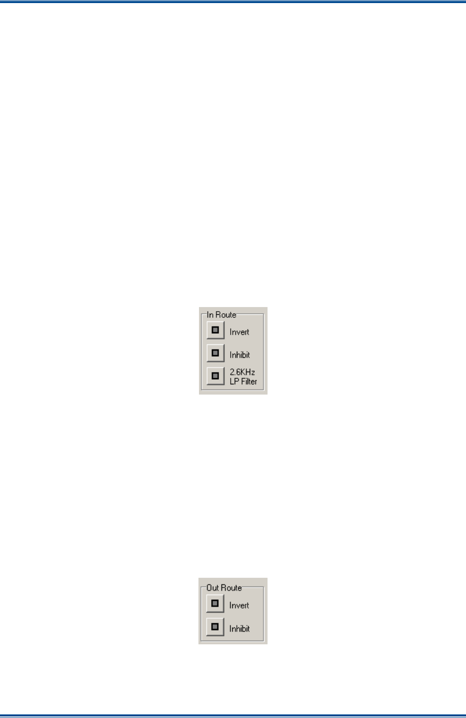
SGD-SB2025NT-TUM, Part 2
Jan 12 Page 44
SOLAR COMMISSIONING
Note.
A change in the coarse gain setting will cause the PLL to show an error and possibly
an alarm for a short duration.
5.2.1.5 In Route
The ‘In Route’ functions available for an Analogue system are shown below in
Figure 33
. For a
P25 system, only the inhibit function is available. Details of the functions are:
(a).
Invert
. When the ‘Invert’ option is selected, the phase of the audio input signal will be
inverted (phase reversal). Whilst this function is not normally required, it does provide a
useful facility in the advent that the audio wiring between NI and base station is suspected as
being reversed.
(b).
Inhibit
. When the ‘Inhibit’ option is selected, the audio signal fed in will be inhibited in the NI,
which will cause a flashing
Red
warning indication on the front panel LED Status indicators.
Depending upon the operational mode and setup configuration of the NI, these inhibits will
also result in the Tx key or voting functions being inhibited, i.e. all associated input signalling
will also be inhibited.
(c).
2.6KHz LP Filter
. When this option is selected, the incoming audio will be low-pass filtered
to 2.6 kHz to prevent signalling tones such as tone RSSI or transmit keytone from passing
through Solar.
Figure 33. In Route functions.
5.2.1.6 Out Route
The ‘Out Route’ functions available for an Analogue system are shown below in
Figure 34
. Again,
for a P25 system, only the inhibit function is available. Details of the functions are:
(a).
Invert
. When the ‘Invert’ option is selected, the phase of the audio output signal will be
inverted (phase reversal). Whilst this function is not normally required, it does provide a
useful facility in the advent that the audio wiring between NI and base station is suspected as
being reversed.
(b).
Inhibit
. When the ‘Inhibit’ option is selected, the audio and any associated signalling that is
output from the NI will be inhibited and a flashing
Red
warning indication will be visible on the
front panel LED Status Indicators.
Figure 34. Out Route functions.
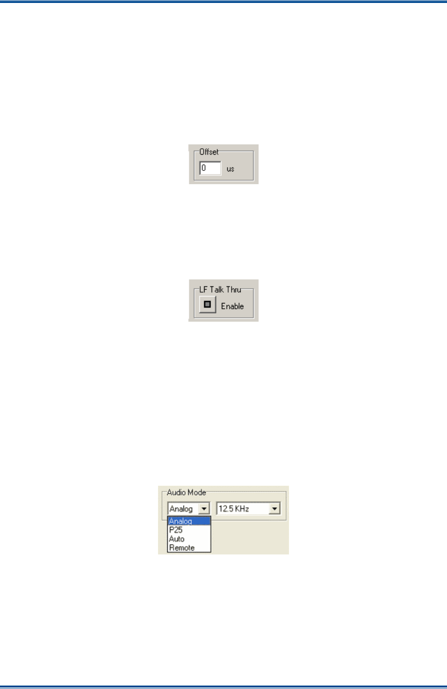
SGD-SB2025NT-TUM, Part 2
Jan 12 Page 45
SOLAR COMMISSIONING
5.2.1.7 Offset
The ‘Offset’ facility (see
Figure 35
below) is provided in order to adjust the relative delay of the
audio output if there is a need to artificially compensate for signal overlap areas that are not
equidistant from sites. The range of delay available is from 0 µs to 255 µs and the required value
is entered directly. An entry that exceeds the maximum will automatically be changed to 255 µs
when applied.
The delay setting is also applied to the CTCSS output if that is used.
Whilst an offset delay may be set on a Central NI it has no effective meaning.
Figure 35. Offset facility.
5.2.1.8 LF Talk Thru
In the event that network communications (line fail) with the TM are lost, setting this facility will
“Enable” Local Station T/T (repeat mode).
Although ‘LF Talk Thru’ may be enabled on a Central NI, it has no meaning.
Figure 36. LF Talk Thru facility.
5.2.1.9 Audio Mode (P25 only)
The ‘Audio Mode’ is only available on a P25 system and can be set to ‘Remote’, ‘Analogue’, ‘P25’
or ‘Auto’. When set to ‘Remote’, the Station NI follows the Audio Mode of the channel it is
assigned to. The Analogue modes are 12.5 kHz and 25 kHz to match the SB2025 bandwidth
setting.
Note.
On a working site, setting the Audio Mode to anything other than ‘Remote’ can end up
with this station being at odds with others on the channel, which can cause a
degradation in overall transmitted signal quality in overlap areas,
Figure 37. Audio Mode facility (P25 only).
5.2.2 Signalling
The input and output signalling, which may be dry contact, tone or a mixture of both, is configured
on the ‘NI Engineering’ ‘Signalling’ page. If this page is viewed through the TM ET there will be a
tab ‘Alarms’ for the ‘Isolated Inputs’ that is not shown on the NI ET – see
Section 12 – Alarms
for
full details of this function.
The ‘Signalling’ page of the NI Engineering facility is shown overleaf in
Figure 38
.
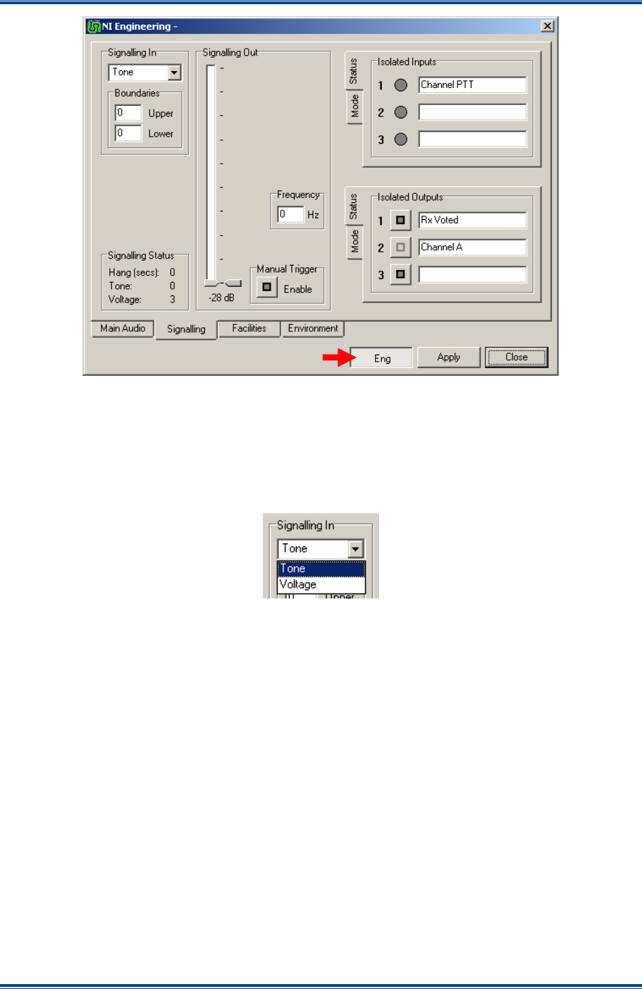
SGD-SB2025NT-TUM, Part 2
Jan 12 Page 46
SOLAR COMMISSIONING
Figure 38. NI Engineering – Signalling page.
5.2.2.1 Signalling In
The signalling input may take the form of a variable voltage or tone. The NI will automatically
determine the meaning of this input according to the mode of operation, i.e. Central or Station,
although setting to ‘Voltage’ has no meaning for an NI operating in Central mode. The type of
signalling required is selected from the drop-down list as shown in
Figure 39
.
Figure 39. Signalling In – Menu Options.
If a voltage input is used, it must be wired to the dedicated input on the NI Facilities connector (see
Table 7
). A signalling tone must be applied to the composite audio input.
Note.
On a P25 system, the Signalling tab of the NI Engineering window differs only in that
the ‘Signalling In’ box is always set to ‘Voltage’ mode because there is no tone RSSI
available from the SB2025 in P25 mode.
5.2.2.1.1 Voltage
Voltage I/P used as RSSI in Station Mode.
The voltage input range is from 0 V to +5 V and this is measured and reported as a value from 0 to
1023 respectively. The ‘Boundaries’ boxes (see
Figure 40
overleaf) define the maximum and
minimum values, and an input level between these limits will be translated into one of the 14 Solar
internal RSSI levels. An input below the minimum value will be regarded as no signal, whereas an
input greater than the maximum value will continue to be regarded as the top RSSI level. Setting a
minimum value of zero disables the function.
The setup process for the RSSI input levels is as follows:
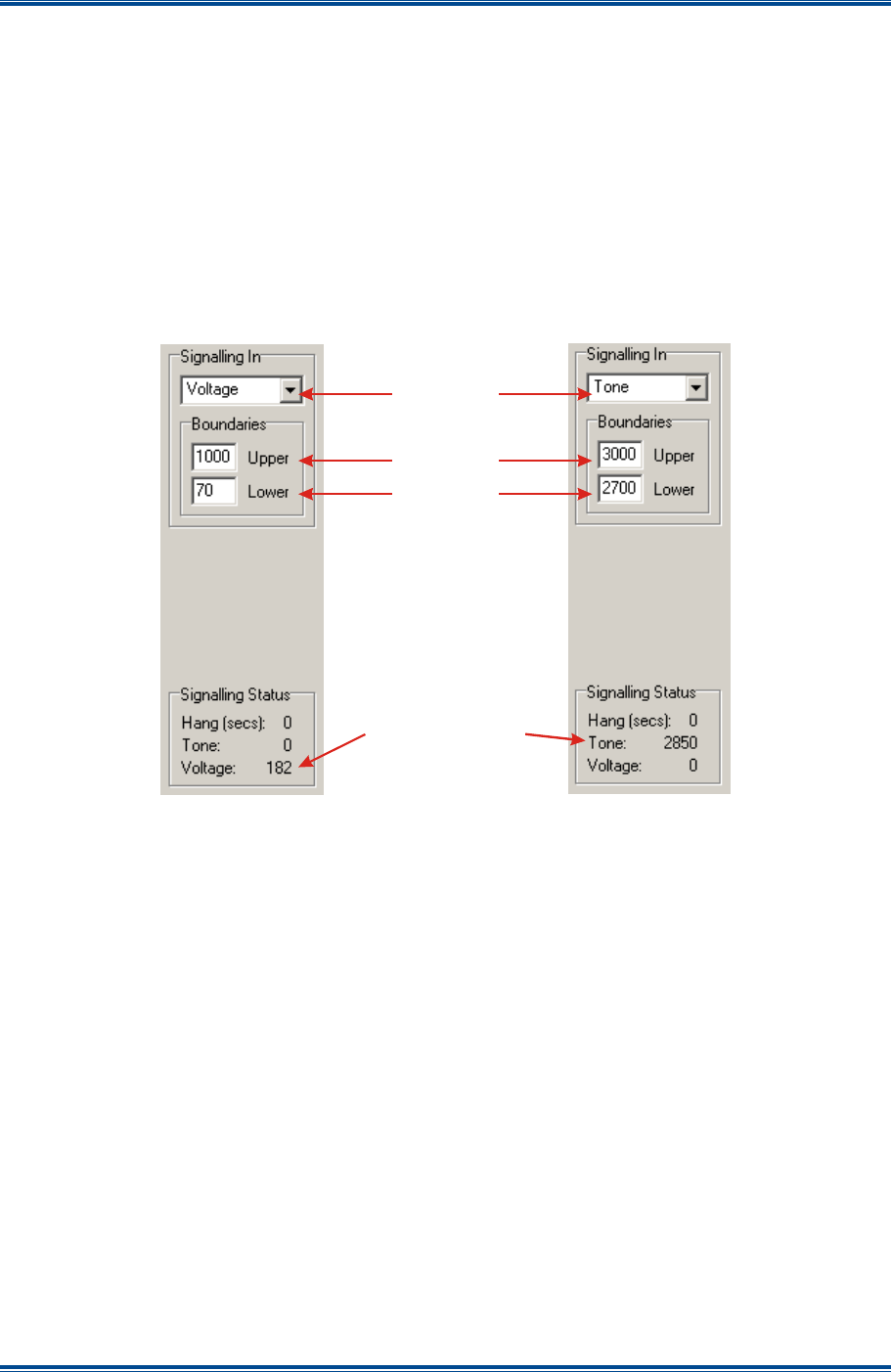
SGD-SB2025NT-TUM, Part 2
Jan 12 Page 47
SOLAR COMMISSIONING
1. Apply a signal level to the Rx of minimum RSSI, typically a mute threshold level.
2. Subtract 10 (see note) from the ‘Signalling Status’ measured value of voltage and enter this
into the minimum Boundary box.
Note.
The subtract figure above is a suggested value to help ensure that the NI does not cut
off low level signals when the receiver squelch may still be open (squelch hysteresis).
3. Apply a signal of maximum RSSI.
4. Enter the ‘Signalling Status’ measured value of voltage into the maximum Boundary box.
Figure 40. Signalling In Configurations.
5.2.2.1.2 Signalling Status
The report of the incoming signal is displayed in this area. Also shown is the ‘Hang’ time in
seconds. This is the time that the transmitters will remain keyed after the channel PTT instruction
has been removed as defined in the TM channel configuration – see
Section 5.4.3.1
.
5.2.2.2 Signalling Out
This facilitates the use of a signalling tone output. The signalling tone is enabled by setting a valid
frequency (0 Hz = Off). When enabled, the tone is switched on:
• for Station NI mode when Tx PTT is active;
• for Central NI mode when a voted signal is present.
Both level and frequency can be set as required (see
Figure 41
overleaf).
Input Type
Maximum
Minimum
Measured Value
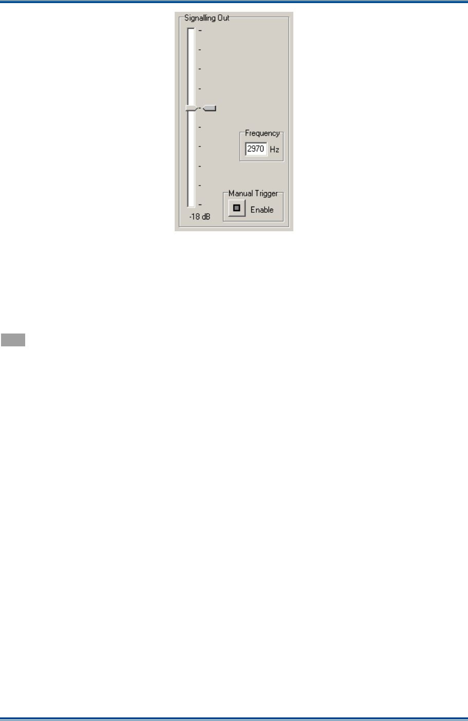
SGD-SB2025NT-TUM, Part 2
Jan 12 Page 48
SOLAR COMMISSIONING
Figure 41. Signalling Tone Output.
The frequency range is 2.5 kHz to 3.5 kHz and, consequently, values entered outside this range
will be changed to the closest limit when the ‘Apply’ button is selected. The tone level setting is in
2 dB steps covering the range of −10 dB to −28 dB relative to the peak system audio level, i.e. it is
not an absolute level. The current level setting is shown at the foot of the slider.
When a level change is applied the marker alongside the slider will turn
Blue
until the change is
confirmed whereupon the position of the marker will match that of the slider control pointer and turn
Grey
again.
Note.
For FW Config builds other than 0x7FFF, the operation of this facility may be different.
See Section 15 – Firmware Extensions for more information.
5.2.2.3 Manual Trigger
For a Station NI this facility provides a simple means to apply a Tx PTT “ON” condition for test
purposes. For a Central NI this becomes the “Rx Voted” output (if used). Whether it is a relay, a
tone or both that is activated depends on what has been configured for the function.
If this facility is used and then the network connection to the Station NI fails, rather than leaving the
Tx keyed indefinitely, under this situation the function will cancel automatically otherwise it must be
cancelled manually. However, activating the facility is indicated on the NI mode panel of the status
page on the ET as a warning – see
Section 3.2
.
5.2.2.4 Isolated Inputs
The state of the Isolated Inputs is presented on the ‘Status’ page (this is the default view) and
configured on the ‘Mode’ page. The Isolated Inputs ‘Status’ page and ‘Mode’ page are shown
overleaf in
Figure 42
.
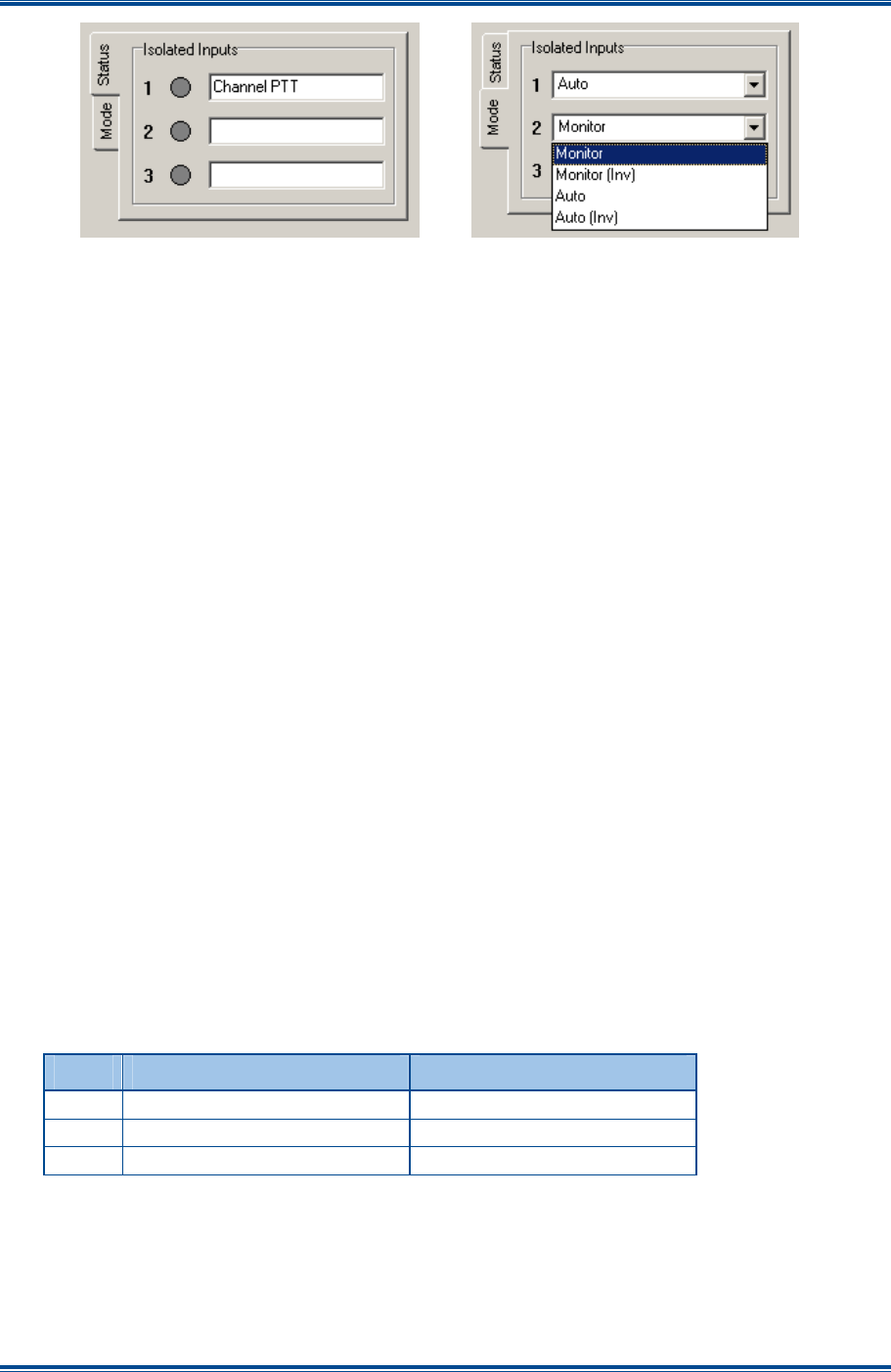
SGD-SB2025NT-TUM, Part 2
Jan 12 Page 49
SOLAR COMMISSIONING
Figure 42. Isolated Input Options.
Each input is assigned to either a ‘Monitor’ mode, which provides a visual indication of the status of
an input, or an ‘Auto’ mode, which pre-defines the duty of each input as shown overleaf in
Table 1
.
The ‘(Inv)’ option of each setting inverts the “ON” state of the input; i.e. in non-inverted mode the
indicator and any associated function is “ON” when the input is taken low, in the inverted mode the
indicator and function is “ON” when the input is taken high or left open circuit.
To change the mode of an input, carry out the following:
1. On the ‘NI Engineering’ window, select the ‘Eng’ button (IN).
2. On the ‘Signalling’ page, select the ‘Isolated Inputs – Mode’ tab to access the ‘Mode’ page.
3. On the ‘Mode’ page, for the input in question, using the drop-down list, select the mode
required.
Note.
On the Isolated Inputs Status page, there is provision for the user to enter a text label
of choice against each input as a reminder of the role assigned to the input.
4. On the ‘Signalling’ page, select the ‘Isolated Inputs – Status’ tab to access the ‘Status’ page.
5. On the ‘Status’ page, for the input in question, click in the text box and enter or amend the
text as required.
6. On the ‘NI Engineering’ window, select the ‘Apply’ button.
More than one item may be changed at a time but the action must be completed by selecting
‘Apply’. At this point, any new setting or text will turn
Blue
until full confirmation is received from
the opposing end of the system. For text labels this will take several minutes as text is given
lowest priority in the supervisory process.
Table 1. Isolated I/P Functions.
Input Central NI Station NI
#1 Channel Tx Key (PTT) Rx squelch open (COR)
#2 Controlled T/T No function assigned
#3 No function assigned SB2000 Alarm state
The use of Input #1 at a Station NI to indicate receiver squelch status is not mandatory as the
‘Signalling In’ facility can be setup to provide this function (see
Section 5.2.2.1
).
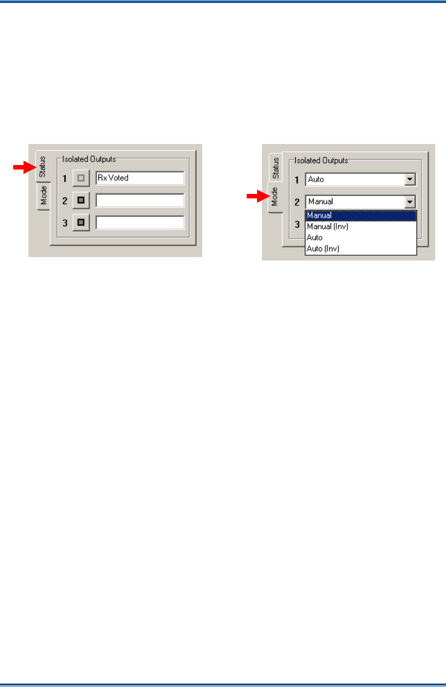
SGD-SB2025NT-TUM, Part 2
Jan 12 Page 50
SOLAR COMMISSIONING
Note.
For FW Config builds other than the standard 0x7FFF, the Auto modes may produce a
different operation to that shown in Table 1. See Section 15 – Firmware Extensions for
more information.
5.2.2.5 Isolated Outputs
Control of the isolated outputs (relays) and their current state is presented on the ‘Status’ page
(this is the default view) and configured on the ‘Mode’ page. The Isolated Outputs ‘Status’ page
and ‘Mode’ page are shown below in
Figure 43
.
Figure 43. Isolated Output Options.
Each output is assigned to either a ‘Manual’ mode, which allows manual control of the output relay
or an ‘Auto’ mode, which pre-defines the duty of the output relay as shown overleaf in
Table 2
.
Once assigned to either of the two auto modes, the button to manually activate the output
becomes unavailable (greyed out).
The ‘(Inv)’ option of each setting inverts the “ON” state of the output with respect to the button
state; i.e. in non-inverted mode the output is “ON” when the button is ‘IN’, in the inverted mode the
output is “ON” when the button is ‘OUT’.
To change the mode of an output, carry out the following:
1. On the ‘NI Engineering’ window, select the ‘Eng’ button (IN).
2. On the ‘Signalling’ page, select the ‘Isolated Outputs – Mode’ tab to access the ‘Mode’ page.
3. On the ‘Mode’ page, for the output in question, using the drop-down list, select the mode
required.
Note.
On the Isolated Outputs Status page, there is provision for the user to enter a text
label of choice against each output as a reminder of the role assigned to the output.
4. On the ‘Signalling’ page, select the ‘Isolated Outputs – Status’ tab to access the ‘Status’
page.
5. On the ‘Status’ page, for the Output in question, click in the text box and enter or amend the
text as required.
6. On the ‘NI Engineering’ window, select the ‘Apply’ button.
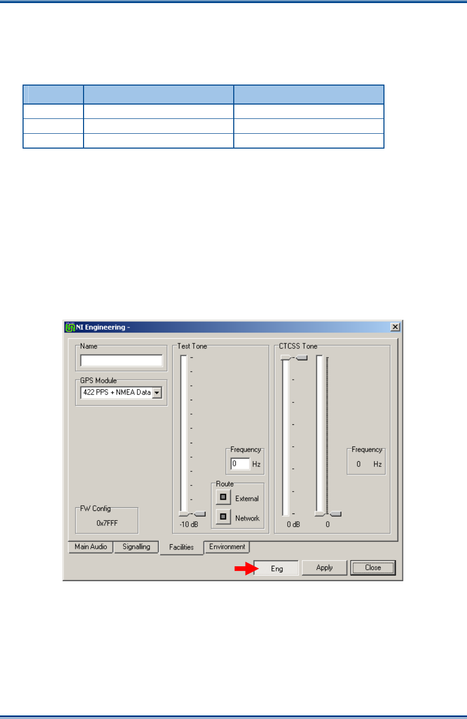
SGD-SB2025NT-TUM, Part 2
Jan 12 Page 51
SOLAR COMMISSIONING
More than one item may be changed at a time but the action must be completed by clicking ‘Apply’.
At this point any new setting or text will turn
Blue
until full confirmation is received from the
opposing end of the system. For text labels this will take several minutes as text is given lowest
priority in the supervisory process.
Table 2. Isolated O/P Functions in ‘Auto’ mode.
Relay O/P
Central NI Station NI
#1 Voted signal present Tx Key (PTT)
#2 System/Channel Alarm ON No function assigned
#3 No function assigned No function assigned
Note.
For FW Config builds other than the standard 0x7FFFF, the Auto modes may produce
a different operation to that shown in Table 2. See Section 15 – Firmware Extensions
for more information.
5.2.3 Facilities
The ‘NI Engineering – Facilities’ page provides access to: the NI text label ‘Name’; the selection of
the signals presented to the GPS module; the setting of the ‘Test Tone’ frequency and level; and
the ‘CTCSS Tone’ level.
The ‘Facilities’ page of the NI Engineering facility is shown below in
Figure 44
.
Figure 44. NI Engineering – Facilities page.
When viewing this page through the NI ET (as in
Figure 44
above), there is facility for setting NI
alarms that is not visible; this is only presented on the TM ET – see
Section 12 – Alarms
for full
details of this function.
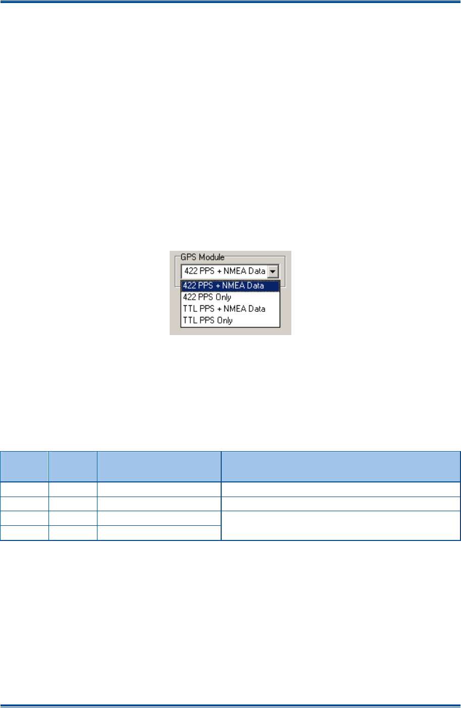
SGD-SB2025NT-TUM, Part 2
Jan 12 Page 52
SOLAR COMMISSIONING
5.2.3.1 Name
This is a user defined text label to aid identification of the NI. The name will be displayed in some
of the TM ET windows to assist the user by confirming that the NI being viewed or altered is the
correct one. To enter or change the text select the ‘Eng’ button (IN), click in the ‘Name’ text box
and amend the text as required (the limit is 19 characters). As for all settings, a change must be
completed by using ‘Apply’.
At this point the text will turn
Blue
until full confirmation is received from the opposing end of the
system, which will take several minutes as text is given lowest priority in the supervisory process.
5.2.3.2 GPS Module
The passage of audio through a NI is dependant upon packet timing, which, in turn, is governed by
the 1PPS timing signal. Therefore, it is important that the configuration and connections match the
type of timing signal to be used, as well as the signal being present and correct before full
commissioning is attempted.
As the GPS/1PPS timing signal connects to a separate and independent sub-module, these
settings will be accessible to other main module(s) that may be fitted to the Solar 2 unit.
Figure 45. GPS Module Timing Source Menu Options.
The timing signal may be one of two signal voltage types each with or without NMEA data; the
latter must be at RS422 voltage levels. The default setting is ‘422 PPS + NMEA Data’ and
changing to either of the TTL 1PPS options will necessitate that the TTL input is used on the GPS
connector (see
Part 1, Section 4.1.2.1 – GPS (1PPS Timing Signal Input
). When NMEA data is
in the selected option, loss of that data will cause a PPS fail indication even if the 1PPS signal is
still present and correct.
Table 3. NI Timing Signal Options.
1PPS
Signal
NMEA
Data Selection Option Notes
RS422 RS422 422 PPS + NMEA Data Setting for use with GPS Ae/Rx
RS422 None 422 PPS Only
TTL RS422 TTL PPS + NMEA Data
TTL None TTL PPS Only
The TTL I/P connection must be used if one of
these two options is selected
5.2.3.3 Test Tone
5.2.3.3.1 Level
The test tone level has 11 fixed values and is calibrated relative to the peak audio output level (see
Section 5.3.2.4
). It has a range of 0 dB (peak) to −10 dB (below peak) in 1 db steps plus a step of
-4.4 dB which equates to 60% of PSL.
5.2.3.3.2 Frequency
The test tone frequency range is 300 Hz to 2500 Hz and the required frequency is entered in the
box in Hz. Entering a value outside this range other than zero will cause the setting to change to
the nearest limit when the setting is applied.
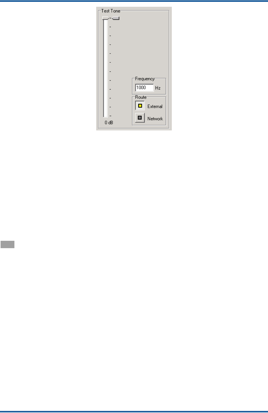
SGD-SB2025NT-TUM, Part 2
Jan 12 Page 53
SOLAR COMMISSIONING
Figure 46. Test Tone Facility.
5.2.3.3.3 Route
The test tone may be sent to either the ‘External’ (the analogue output), ‘Network’ towards the TM
or both by setting that route to “ON”. It is the selection of the ‘Route’ that activates the test tone.
Selecting the ‘Network’ route at a Station NI will need to be accompanied by a valid RSSI level
(and mute open condition if so configured) for the test tone to pass through the TM and be output
from the Central NI. The tone will be re-broadcast if channel T/T is selected.
Selecting the ‘Network’ route will result in the ‘In Audio Sensitivity’ gauge displaying a level in
sympathy with the test tone level while the network is connected. When a ‘Route’ is selected the
indication on the front status page (see
Section 2.2.1.2
) will be present to warn the user that it is
active and that normal operation is suspended.
When a level change is applied the marker alongside the slider will turn
Blue
until the change is
confirmed whereupon the position of the marker will match that of the slider control pointer and turn
Grey
again.
Note.
If a frequency of 0 Hz is entered and a ‘Route’ selection is made, no tone will be output
and the normal audio path in the ‘Route’ direction will be suspended.
5.2.3.4 CTCSS Tone
The CTCSS Tone Level is set to meet the required output using the coarse level (left slider) and
fine level (right slider) controls (see
Figure 47
overleaf). The coarse gain steps are 3 dB and the
fine slider gives a 6 dB range of control. The current settings are shown by the marker to the right
of the slider and the value at the bottom.
When a level change is applied the marker alongside the slider will turn Blue until the change is
confirmed whereupon the position of the marker will match that of the slider control pointer and turn
Grey again.
Whilst the CTCSS Tone frequency can only be set centrally at the TM to ensure all sites within a
channel generate the same CTCSS frequency (see
Section 5.4.3.2
), the frequency setting is
reported here for convenience.
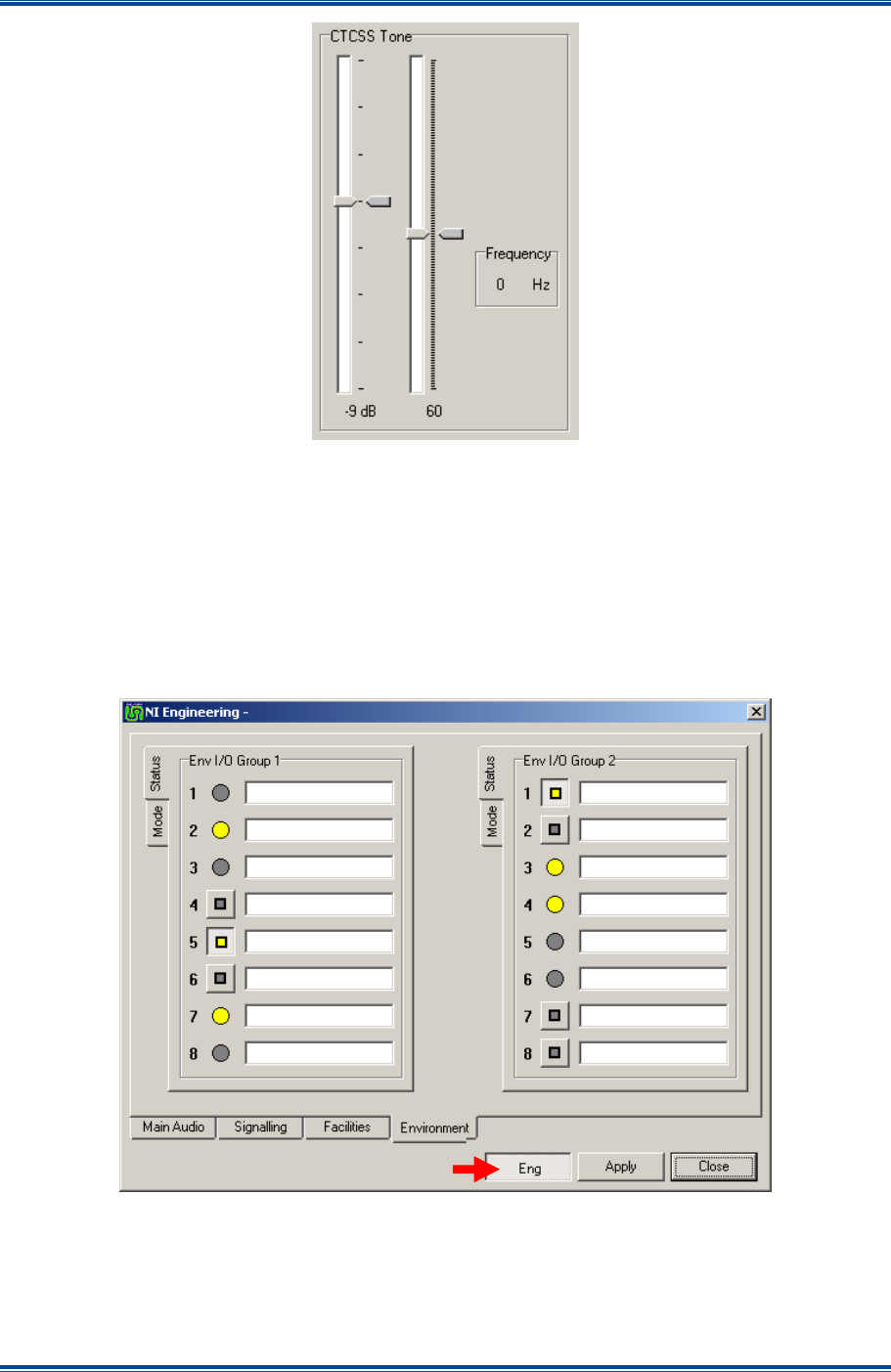
SGD-SB2025NT-TUM, Part 2
Jan 12 Page 54
SOLAR COMMISSIONING
Figure 47. CTCSS Tone level.
5.2.4 Environment
The ‘Environment I/O’ interface is an independent sub-module within the Solar 2 unit. It is
accessible from and available to any of the main modules that are fitted to the unit. Consequently,
any action or setting applied through one module is visible to and open to change through another
module. If this page is viewed through the TM ET there will be tabs for ‘Alarms’ that are not shown
on the NI ET – see
Section 12 – Alarms
for full details of this function.
The ‘Environment’ page of the ‘NI Engineering’ facility is shown below in
Figure 48
.
Figure 48. NI Engineering – Environment page.
These connections are arranged in two groups of eight, which reflects the fact that each point in
the group is electrically connected to the same physical device (integrated circuit). This has no
significance as far as operation is concerned but will limit the total load current that can be
switched by all the outputs in a group – see
Part 1, Section 3.2
. The following information applies
equally to both groups.
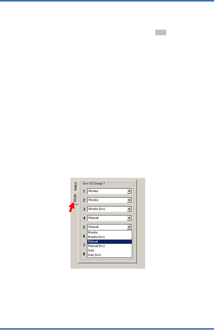
SGD-SB2025NT-TUM, Part 2
Jan 12 Page 55
SOLAR COMMISSIONING
5.2.4.1 Status
The state of the inputs and control of the outputs is presented on the ‘Status’ page for each group,
which is the default view. To change the state of an output, select the ‘Eng’ button (IN), select the
button of the required output(s) then select ‘Apply’ to invoke the change. The inner square of the
button will turn
Blue
until the change is confirmed whereupon it will turn
Grey
again.
Each item has a text label available that is designed to help the user confirm that the individual
input/output that is being examined or controlled is the correct one; the text plays no part in the
operation of the unit and can be omitted. The text entered via this page will be presented on the
main status page of the NI and on some of the TM ET windows.
To enter or change the text, select the ‘Eng’ button, click in the text box for the required
input/output and enter or amend the text as required (the limit is 20 characters). As for all settings,
a change must be completed by using ‘Apply’. At this point the text will turn
Blue
until full
confirmation is received from the opposing end of the system, which will take several minutes as
text is given lowest priority in the supervisory process.
5.2.4.2 Mode
Each connection point is able to operate as an input or an output, which is defined by the option
selected from the drop-down list. The setting of ‘Monitor’ or ‘Monitor (Inv)’ dictates that the point
will be an input; any other setting dictates the point will be an output.
The ‘Monitor (Inv)’ option inverts the “ON” state of the input; i.e. in non-inverted mode the indicator
and any associated function is “ON” when the input is taken low, in the inverted mode the indicator
and function is “ON” when the input is taken high or left open circuit.
The ‘Manual (Inv)’ option inverts the “ON” state of the output with respect to the button state; i.e. in
non-inverted mode the output is “ON” when the button is “IN”, in the inverted mode the output is
“ON” when the button is “OUT”.
Figure 49. Environment Mode settings.
Note.
For FW Config builds other than the standard 0x7FFF, whilst the indicator will function
as described above, when ‘Auto’ or ‘Auto (Inv)’ mode is selected, either setting may
invoke a different or additional action. See Section 15 – Firmware Extensions for more
information.
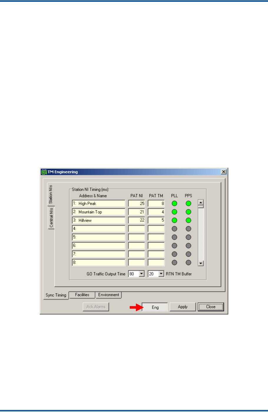
SGD-SB2025NT-TUM, Part 2
Jan 12 Page 56
SOLAR COMMISSIONING
5.3 TM
E
NGINEERING
(TM
ET
O
NLY
)
‘TM Engineering’ is accessed by clicking on the ‘Eng’ button on the TM Status panel. The settings
accessed in the following pages are stored in the TM, some being sent to the NI for configuration
purposes as part of the Solar supervisory system, others are sent for information purposes only.
The ‘TM Engineering’ window also has an ‘Eng’ button that must be selected (IN) before a change
can be made, whereupon the ‘Apply’ button will become active. Changes in settings will not
become active until the ‘Apply’ button is selected. The ‘TM Engineering’ window is closed by
selecting the ‘Close’ button or by using the close icon
in the top right hand corner. Any changes
made but not applied will be lost when the window is closed.
Also visible on the ‘TM Engineering’ window is an ‘Ack Alarms’ button, which will be unavailable
(greyed out). See
Section 12 – Alarms
for full details of this function.
5.3.1 Sync Timing
The purpose of ‘Sync Timing’ is to facilitate setting the size of the Solar packet buffers that are
crucial to the correct operation of a Solar simulcast radio network. Due to the detailed nature of
the subject, the information is presented in full detail in
Section 7 – Solar (Sync) Timing
of this
manual. The user is well advised to study this section carefully prior to system optimisation.
At the initial commissioning stage “nominal” values will be used to get the system operating.
Figure 50. TM Engineering – Sync Timing (Station NIs).
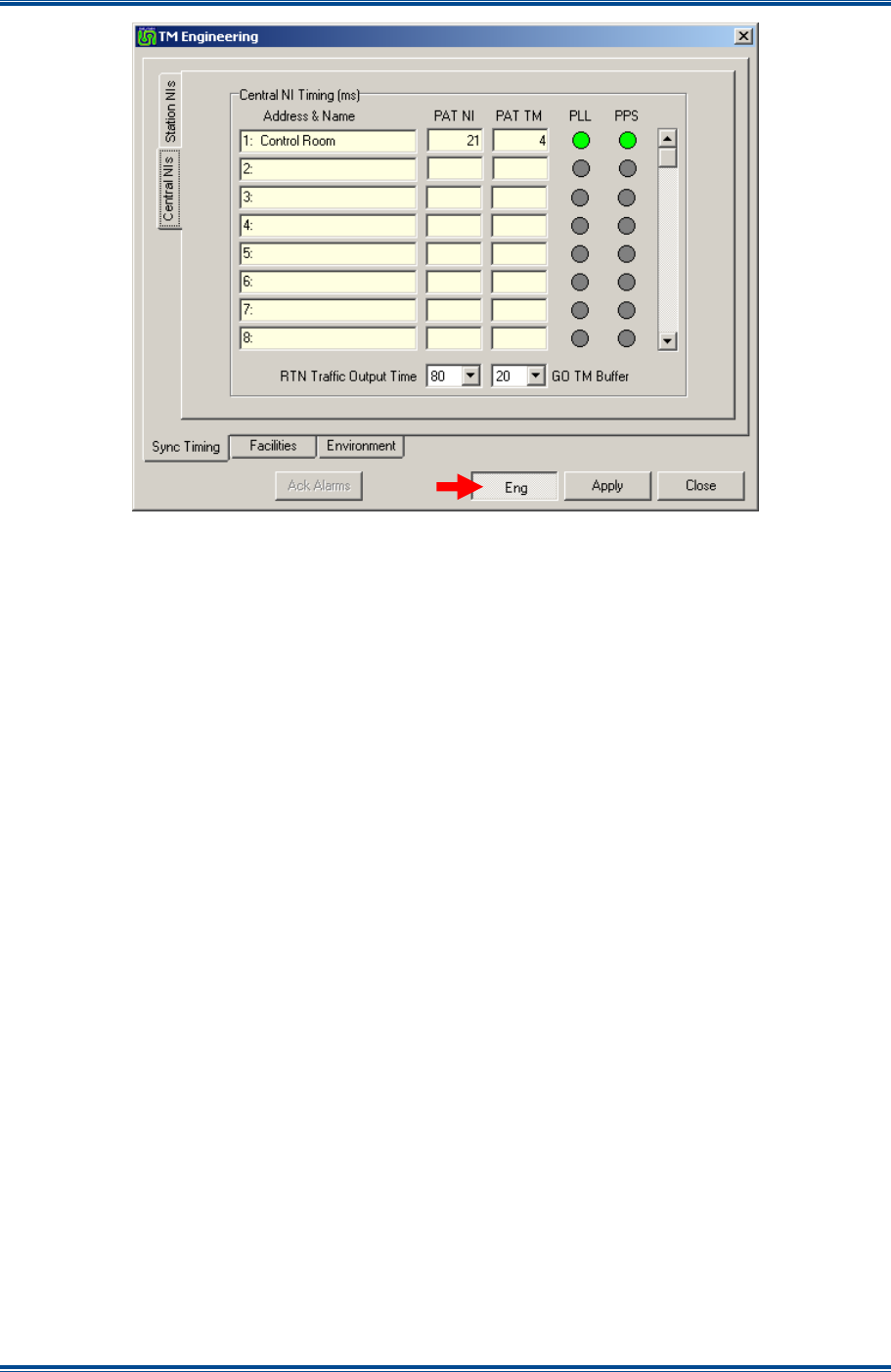
SGD-SB2025NT-TUM, Part 2
Jan 12 Page 57
SOLAR COMMISSIONING
Figure 51. TM Engineering – Sync Timing (Central NIs).
There are two ‘Sync Timing’ pages; one for the Station NI and one for the Central NI, each being
selected by the corresponding tabs as seen in
Figures 50 and 51
above. If the number of the NI
in use exceeds the capacity of the display area, the slider to the right of each table allows the
display area to be moved up and down to view every report.
Each page has two buffer settings where values are taken from the drop-down lists. As the buffer
settings are inter-dependant, the Central NI page must be used to complete the set-up process
even on a system that has no Central NI.
5.3.1.1 PAT Reports
A brief explanation of the terminology used on the ‘Sync Timing’ pages is given here for
completeness.
The ‘PAT’ values are calculated by every unit receiving packets. For each NI, that information is
passed back to the TM for display on this page, together with the figures calculated by the arrival
time of packets at the TM itself. The measurements and reports take place once a second.
‘PAT NI’ is the average time taken for packet zero to arrive at a NI (rounded up to the nearest
millisecond).
‘PAT TM’ is the average time taken for packet zero to arrive at the TM (rounded up to the nearest
millisecond).
The ‘PLL’ indication confirms the health of the phase locked loop within the NI and the ‘PPS’
indication confirms the health of the 1PPS timing signal within the NI.
Note.
The PAT value reported from a NI that is indicating loss of PPS may not be correct.
Similarly, the ‘PAT TM’ report depends on the TM PPS signal being present.
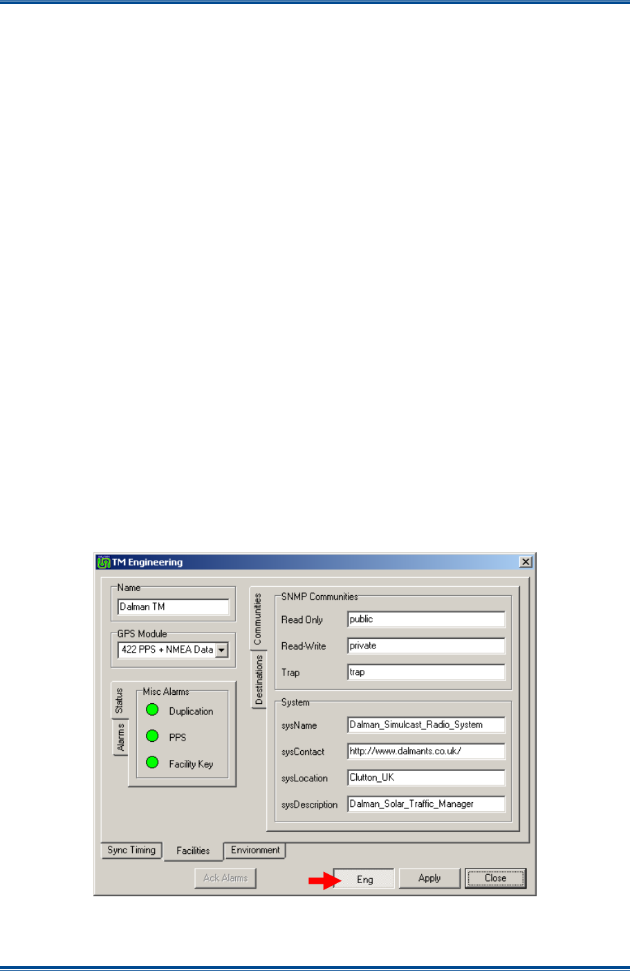
SGD-SB2025NT-TUM, Part 2
Jan 12 Page 58
SOLAR COMMISSIONING
5.3.1.2 Initial Values
The principle is to start with nominal values and assume that these settings will require adjustment
to values better suited to the IP network. This is especially true if the network has a means of
alternate routing or fallback as the configuration offering ‘worst case’ values must be considered.
Note.
These buffer parameter values are global and apply to all channels on a multi-channel
system.
It is necessary to depress the ‘Eng’ button before any setting may be selected from the drop-down
lists (there is no direct entry of values). Any changes must be saved by selecting ‘Apply’.
The suggested settings that are likely to be satisfactory for the majority of networks so that the
initial commissioning may be instigated are:
(a). ‘GO TM Buffer’ and ‘RTN TM Buffer’ set to 60 ms.
(b). ‘GO Traffic Output Time’ and ‘RTN Traffic Output Time’ set to 120 ms.
If network latency is believed to be significant, increasing all settings by a further 40 ms may be
necessary. All times are in 20 ms steps.
5.3.2 Facilities
The item of primary importance on the ‘Facilities’ page is that of selecting the right format of signal
input for the ‘GPS Module’. If the Solar 2 unit also supports an NI, the setting of the ‘GPS Module’
may have already been undertaken through that route. Apart from being able to allocate a ‘Name’
to the TM, the other areas on this page are covered in the ‘Alarms’ and ‘SNMP’ sections of this
manual.
The ‘Facilities’ page of the ‘TM Engineering’ facility is shown below in
Figure 52
.
Figure 52. TM Engineering – Facilities page.
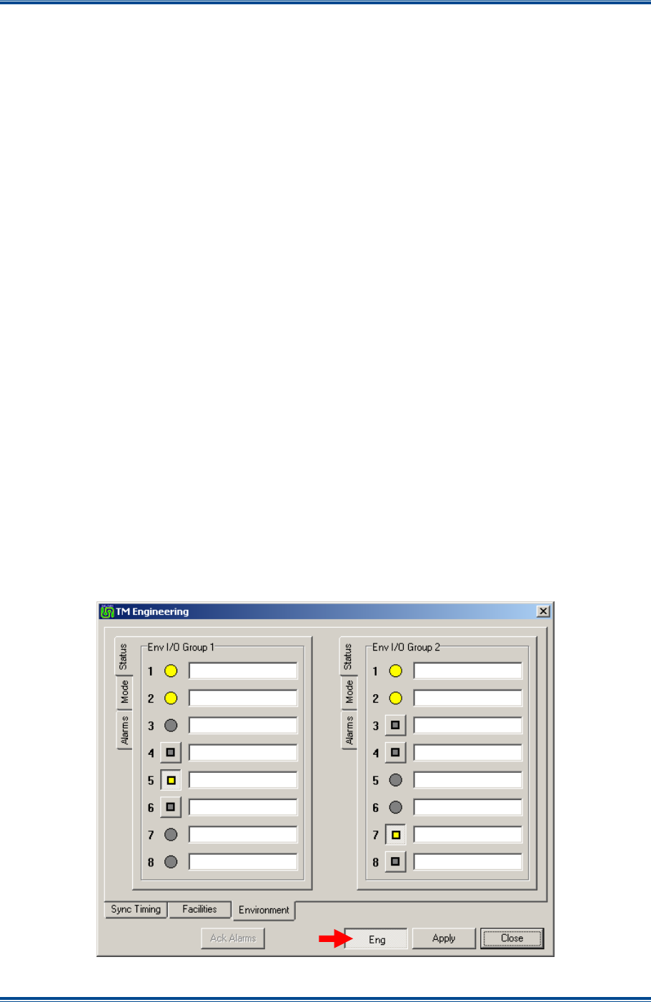
SGD-SB2025NT-TUM, Part 2
Jan 12 Page 59
SOLAR COMMISSIONING
5.3.2.1 Name
To enter or change the ‘Name’ text, select the ‘Eng’ button, click in the ‘Name’ text box and enter
or amend the text as required (the limit is 20 characters). As for all settings, a change must be
completed by using ‘Apply’, which will take immediate effect as the information remains with the
TM; i.e. it is not transmitted through the Solar supervisory system.
5.3.2.2 GPS Module
The GPS/timing interface is an independent sub-module within the Solar 2 unit. It is accessible
from and available to any of the main modules that are fitted to the unit. Consequently, any action
or setting applied through one module is visible to and open to change through another module.
Therefore, refer to
Section 5.2.3.2
on the NI for all the necessary information on the GPS module
options and settings.
5.3.2.3 Misc Alarms
The indicators shown on the ‘Status’ page are a repeat of those presented on the TM Status panel.
The “Alarm’ page is covered under
Section 12 – Alarms
.
5.3.2.4 SNMP
This feature is an option that is controlled by the ‘Facility Key’ and may not be present on all
versions of the TM. The feature is covered under
Section 14 – SNMP
.
5.3.3 Environment
The ‘Environment I/O’ interface is an independent sub-module within the Solar 2 unit. It is
accessible from and available to any of the main modules that are fitted to the unit. Consequently,
any action or setting applied through one module is visible to and open to change through another
module.
Apart from the additional pages for ‘Alarms’ (see
Figure 53
below), the options and settings are
identical to those available to an NI. Therefore, refer to
Section 5.2.3
for all the necessary
information. For full details on the ‘Alarms’ pages see
Section 12 – Alarms
.
Figure 53. TM Engineering – Environment page.

SGD-SB2025NT-TUM, Part 2
Jan 12 Page 60
SOLAR COMMISSIONING
5.4 C
HANNEL
S
ETUP
The ‘Channel Setup’ page for an Analogue system, shown below in
Figure 54
, is accessed via the
‘Setup’ button on the Channel Status Panel of the TM ET main window as shown in
Section 3.4.2
– Channel Status Panel
.
Figure 54. Channel Setup page (Analogue).
Of the parameters that are accessed from this page, those that relate to the operation of receiver
voting are probably the ones that are most likely to have the greater impact upon the successful
operation of the Solar channel. That being the case, whilst there are brief details of each
parameter in the following sections, to complete the information a more in depth description of the
receiver voting function of Solar is given in
Section 10 – Receiver Voting
.
The ‘Eng’ button must be selected to enable changes to be made and the ‘Apply’ must be selected
to complete the changes.
5.4.1 Name
This facility is used to identify each channel to ensure that settings, tests or simply observations
are being applied to or made on the correct channel when operating in a multiple channel
environment.
The ‘Name’ is entered or edited by selecting the ‘Eng’ button then clicking in the ‘Name’ text box,
which allows direct entry of characters into the text box, the limit is 20 characters. The change is
confirmed by selecting the ‘Apply’ button.
5.4.2 Voting Facilities
5.4.2.1 Minimum RSSI Difference
This sets the minimum difference between RSSI levels before the Voter makes a new selection
(sometimes referred to as level hysteresis). The RSSI level size is determined by the values
entered for the NI boundary levels and input signal type (see
Section 5.2.2.1 – Signalling In
).
5.4.2.2 Voter Override
This facilitates the testing of RTN paths. When “ON”, the Voter is forced to select this site and
pass on any speech traffic or test tones from that Station NI. When activated, the ‘Voted Level’
text shows ‘OVR’ and the Station panel displays a
Yellow
voted indication with a full RSSI level
shown as a
Blue
bar. The “OFF” state returns the channel to normal operation.

SGD-SB2025NT-TUM, Part 2
Jan 12 Page 61
SOLAR COMMISSIONING
5.4.2.3 Site Deselection Timer (Minutes)
If an in-service base station Rx squelch is open for longer than this value, that station will be
removed from the Voter list until that squelch is closed continuously for a short time (typically
10 seconds). If invoked, the Station panel will still indicate a received RSSI level but not a voted
indication.
5.4.2.4 TM triggered Talk Through
T/T or repeat mode is implemented in the digital domain within the TM, no matter how the function
is controlled or initiated. The following options refer to the manner in which T/T may be enabled, in
addition to the external application of console/control switched facility through the Central NI. If no
Central NI is in use, the setting ‘Permanent’ will need to be used.
(a).
‘None’
. T/T operation is not enabled.
Note.
T/T is still available as a controlled function via the Central NI if enabled for operation
– see Section 5.2.2.4.
(b).
‘On Central NI Fail’
. Loss of communications between the corresponding Central NI and
the TM will cause T/T to be enabled.
(c).
‘Permanent’
. T/T is permanently enabled.
Note.
When the Control Tx Key function is active, T/T will be suspended, i.e. Control Tx Key
has precedence but will not switch off the T/T function.
5.4.3 Facilities
5.4.3.1 Tx Key Hang
The ‘Tx Key Hang (sec)’ is the time that the Tx PTT is maintained after the Tx Key command has
been removed either as a direct input to the Central NI or after cessation of a received signal when
the channel is operating on T/T. This setting is maintained by a Station NI that is operating in fall
back (Line Fail) T/T.
The range is from OFF (no delay) to 5 seconds (in 1 second increments).
5.4.3.2 CTCSS
A phase coherent CTCSS tone is available from a dedicated output on the Facilities connector of a
Station NI. The tone is generated at the NI from a value that is passed from the TM. The CTCSS
frequency is entered in Hertz in the range of 50 Hz to 300 Hz inclusive (in 0.1 Hz increments). A
value entered outside of this range will be corrected to the closest limit. Entering 0 Hz indicates
that no CTCSS tone is to be generated.
This setting is maintained by a Station NI that is operating in fall back (Line Fail) T/T.
5.5 C
HANNEL
S
ETUP
P25
For a P25 system, the ‘Channel Setup’ page is slightly different and is shown overleaf in
Figure 55
. It is still accessed in the same way via the ‘Setup’ button on the Channel Status Panel
of the TM ET main window as shown in
Section 3.4.2 – Channel Status Panel
.
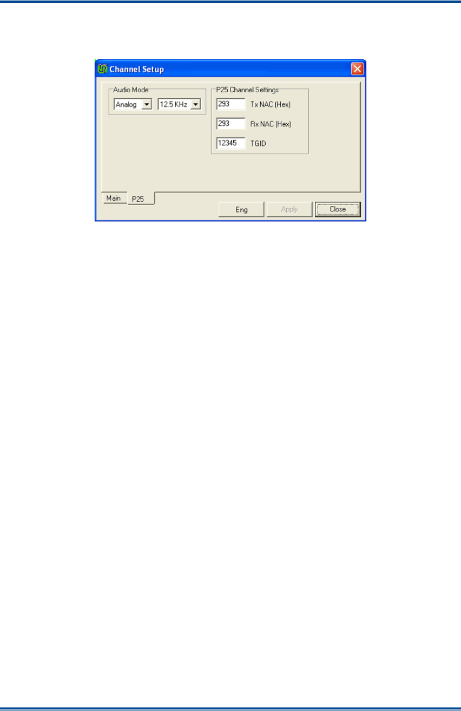
SGD-SB2025NT-TUM, Part 2
Jan 12 Page 62
SOLAR COMMISSIONING
The significant difference is that the page now contains ‘Main’ and ‘P25’ tabs, with the P25
features/parameters accessed via the P25 tab. The Main tab simply contains all the parameters
for an Analogue system, which are detailed in
Section 5.4
above.
Figure 55. Channel Setup page (P25).
The ‘Eng’ button must be selected to enable changes to be made and the ‘Apply’ must be selected
to complete the changes.
5.5.1 Audio Mode
The channel’s Audio Mode is set here. This mode will be adopted by all NIs assigned to this
channel as long as they have their individual Audio Mode set to Remote. (See
Section 5.2.1 -
Main Audio
). In Analogue or Auto mode, the channel bandwidth must be set to either 12.5 kHz or
25 kHz to match the setting in the SB2025 base stations and all the base stations must be set the
same.
5.5.2 P25 Channel Settings
The ‘P25 Channel Settings’ area is where the Tx and Rx Network Access Codes (NAC) are set.
The ‘Tx NAC’ and ‘TGID’ settings will be transmitted for all P25 calls originated by the dispatcher
and for all P25 T/T calls unless the Rx NAC is set to 0xF7F, in which case, the received NAC and
Talk Group Identification (TGID) will be transmitted.
If the ‘Rx NAC’ is set to 0xF7E or 0xF7F, the channel will respond to any P25 transmissions
irrespective of their own Tx NAC, however, if set to anything else, the received NAC must match or
the call will be ignored.
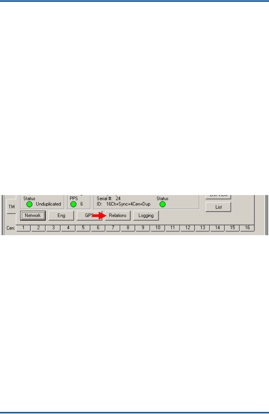
SGD-SB2025NT-TUM, Part 2
Jan 12 Page 63
SOLAR CHANNELS
6 SOLAR CHANNELS (RELATIONS)
6.1 M
ULTI
-C
HANNEL
O
VERVIEW
The ‘Facility Key’ controlled Multi-channel option of the TM allows a collection of Station NI (sites)
to be grouped together and operate as an independent sub-system of the parent Solar network.
These groupings will be referred to as a “Solar Channel” and, although it is anticipated that all base
stations or repeaters on a Solar Channel would be operating on the same radio frequency, it is not
mandatory.
The maximum capacity of a Solar TM is 32 Station NI (sites) and every TM is able to support the
maximum irrespective of any options. A TM can also support up to 16 Channels but will be
programmed for the number according to the option fitted. The Station NI can be distributed
across these channels in any mix of quantities; for example eight channels of four sites each or
four channels with eight sites each and so on. The introduction of Solar 2 has seen the feature
added to have more than one Central NI per channel in order to provide multiple presentations to
Control/Console systems. However, the maximum number of Central NIs per system remains at
16 no matter these are allocated to channels. A channel need not have a Central NI if no
Control/Console connection is required.
6.2 R
ELATIONS
F
UNCTION
6.2.1 NI to Channel Association
The facility to define which Station(s) belong to which channel and to define which Central NI, if
any, will operate a channel is accessed by clicking the ‘Relations’ button on the TM Status panel
(see
Section 3.4.1
).
Figure 56. Route to Relations page.
This will open a window that has three rows of numbered squares: Station NIs across the top;
Channels in the middle; and Central NIs across the bottom. Station squares and Central squares
will only become active when allocated to an NI. Channel squares will be active to the number
authorised on the system.
The example ‘Relations’ page, shown overleaf in
Figure 57
, shows a TM with the 16 channel
option that has six Station NIs and three Central NIs enabled. The ‘Relations’ page is available on
a single channel TM but it serves no purpose in the configuration process.
A Station NI square will be active when the corresponding Station NI panel is enabled and a
Central NI square will be active when the corresponding Central NI panel is enabled. The channel
squares that are active will correspond to the number of channels that have been enabled by the
Facility Key.
At the initial configuration stage, all Station NIs will be associated to channel #1 and the Central NI
will be related to channels on a one to one basis. Once all the NIs that form the Solar network
have been allocated to a Station or Central role and are online, the redefining of relationships
between channels and NI can be undertaken. These relationships are shown by the lines that link
the squares. It is not possible to delete a relationship only to change it.
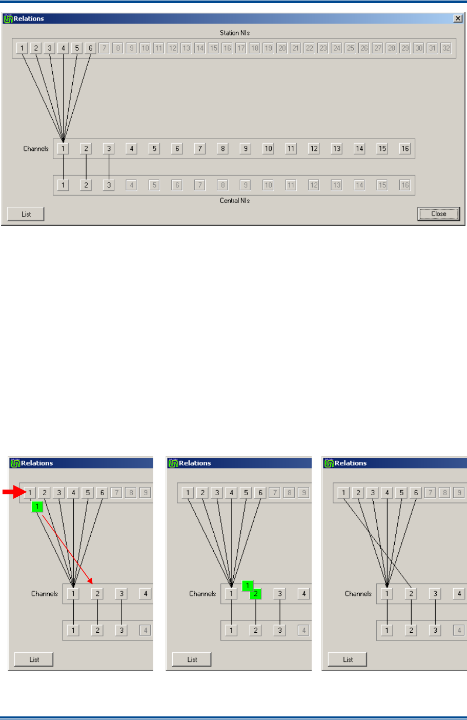
SGD-SB2025NT-TUM, Part 2
Jan 12 Page 64
SOLAR CHANNELS
Figure 57. Relations Page.
6.2.2 Moving a Station to a Different Channel
The following procedure is an example of how to move Station NI #1 from Channel #1 to
Channel #2. The process is also shown in
Figure 58
below.
1. Move the mouse pointer over Station NI#1 square, click and hold the left mouse button.
2. A square with a
Green
highlight and the number 1 in it will appear under the pointer. Drag
this to the Channel #2 square, which will also gain a
Green
highlight.
3. Release the mouse button.
4. The line linking Station NI #1 to Channel #1 will move across to Channel #2.
5. The action is complete.
Figure 58. Moving a Station NI between Channels.
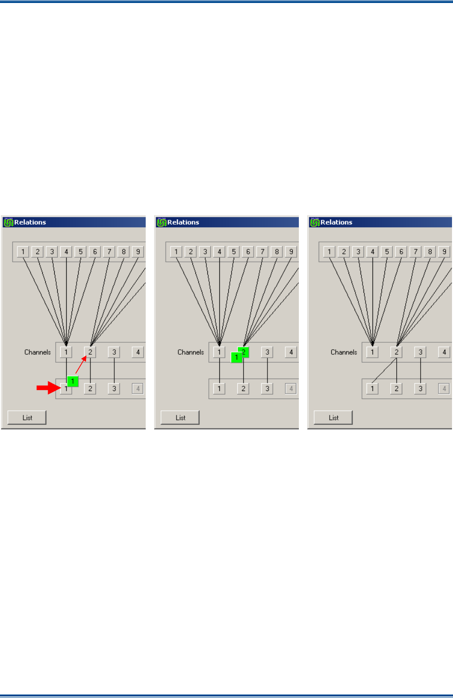
SGD-SB2025NT-TUM, Part 2
Jan 12 Page 65
SOLAR CHANNELS
6.2.3 Moving a Central NI to a Different Channel
The following procedure is an example of moving the Central NI #1 from Channel #1 to
Channel #2. The process is very much the same as moving a Station NI and is shown below in
Figure 59
.
1. Move the mouse pointer over Central NI #1, click and hold the left mouse button.
2. A square with a
Green
highlight and the number 1 in it will appear under the pointer. Drag
this to the Channel #2 square, which will also gain a
Green
highlight.
3. Release the mouse button.
4. The line linking Central NI #1 to Channel #1 will move across to Channel #2 as shown in
Figure 59
below.
5. The action is complete.
Figure 59. Moving a Central NI between Channels.
6.2.4 Disabling and Re-enabling a NI
If a Station or Central NI is disabled this will cause the relationship between that NI and the
channel to cease and the connecting line to disappear. When the NI is re-enabled, the original
relationship will be restored.
A new Central NI added to the system will normally relate to the corresponding Channel number;
i.e. Central NI #3 will connect to Channel #3, Central NI #4 to Channel #4 as so forth.
The example in
Figure 60
shows the effect of disabling Station NI #4.
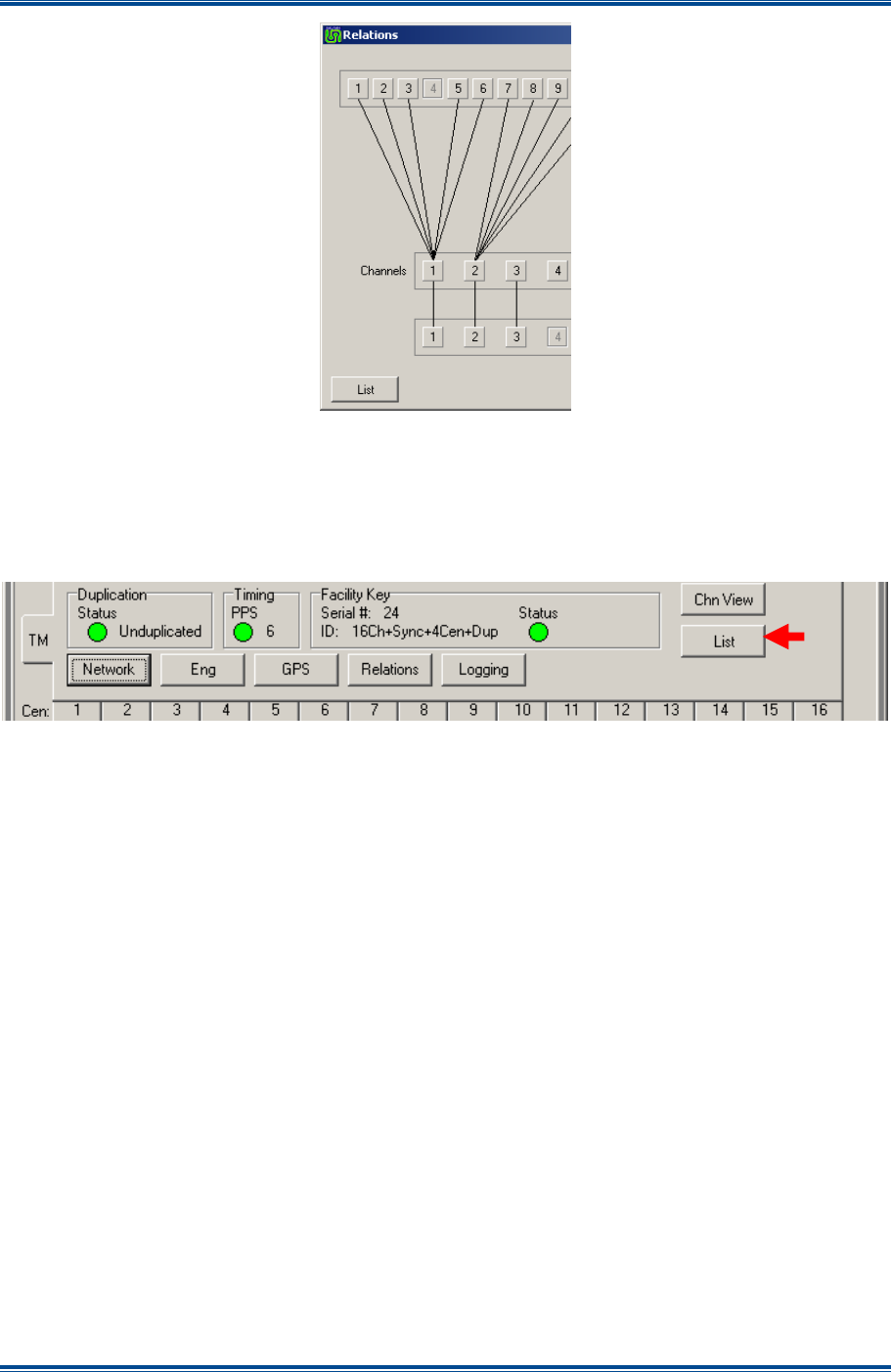
SGD-SB2025NT-TUM, Part 2
Jan 12 Page 66
SOLAR CHANNELS
Figure 60. Examples of disabled NI.
6.3 L
IST
The function of ‘List’ is to present all the NI and Channels that are on the system in a single
window for ease of identification. ‘List’ may be activated directly from the TM Status panel or via
the ‘Relations’ window.
Figure 61. Route to List facility.
There are three lists in the window; one for Stations, one for Channels and one for Centrals. Each
list is on its own page and accessed with the corresponding tab. Each member in the list will be
displayed with its ‘Name’, i.e. the text label attributed to the NI or Channel.
If an NI is currently offline, the name will still be visible but will be greyed out to indicate its offline
status as shown for Station # 4 in
Figure 62
overleaf. An NI that has been “seen” by the TM at
some stage, perhaps during the system staging process, will be retained until over-written by
another; i.e. there is no facility to delete unwanted entries.

SGD-SB2025NT-TUM, Part 2
Jan 12 Page 67
SOLAR CHANNELS
Figure 62. Pages in the ‘List’ window.

SGD-SB2025NT-TUM, Part 2
Jan 12 Page 68
SOLAR (SYNC) TIMING
7 SOLAR (SYNC) TIMING
7.1 G
ENERAL
The purpose of this section is to give the user an understanding of the way in which Solar operates
in the context of packet timing and buffering, which is core to the task of delivering consistent and
reliable audio over an IP network. There is more information on the specific subject of IP network
changes and the effects on Solar operation in
Section 11 – Troubleshooting & Maintenance
.
7.1.1 Synchronising Signals
The first and fundamental issue to be appreciated is that to synchronise multiple signals, which
each pass over different bearer circuits, means that each signal must be delayed by an amount
such that its total end-to-end delay is the same as that of the signal that passes over the route of
longest delay. In other words, hold back the quicker signals until they are each as slow as the
slowest, since it is not possible to make the slower signals travel faster. This is a core principle
and is just the same for Solar as it is for a conventional analogue borne simulcast system.
7.1.2 Network Jitter
There is an additional aspect about the use of IP that is different to conventional bearers and that
is “Network Jitter”. On a stable and robust IP network, IP packets are likely to arrive at a fairly
consistent rate. However, even on good, reliable networks there will be times when packets get
delayed slightly longer than the average, for a variety of reasons. To cater for this situation, it is
necessary to hold packets received at the destination unit in a store or buffer for a short (variable)
time, then output the data at precise intervals to iron out these variations and produce a steady
contiguous audio stream. Larger variations in the packet delivery times require larger buffers,
however, it would be poor practice to use large buffers as a means to overcome a poor quality or
unstable IP network. The user must be satisfied that the IP network is working correctly at the
outset before attempting to optimise Solar ‘Sync Timing’.
7.2 S
OLAR
I
NTERNAL
T
IMING
The 1PPS timing signal is used to generate very accurate timing frames of 20 ms duration and it is
to these frames that Solar is synchronised – this is the function of the PLL in the NI. Therefore,
each 1 second period will contain 50 such frames, which are numbered 0 to 49 with frame 0 (zero)
starting on the rising edge of the 1PPS signal. Since all internal timing events are linked to the
frame clock, Solar’s timing parameters are in 20 ms steps.
7.2.1 Determining the Timing Values
In order to operate correctly, the timing settings must be sufficient to provide buffer periods that
can cater for the longest delay exhibited on the system. It should be recognised that the longest
network delay may not occur during normal operation but under network fault conditions if a
network re-route is applied (see
Section 11.1 – Network Latency and Faults
for further
information on this topic).
The initial approach for commissioning is to set timing periods that will probably prove to be
significantly longer than the network delays. However, these settings will need to be optimised, as
it is likely to result in the end-to-end delay on the audio signal being longer than necessary, which
may be noticeable especially for T/T operation.
7.2.2 PAT Reports
To be able to select the optimum timing values, the average time taken for data packets to arrive at
each unit are calculated and displayed on the TM Sync Timing page. These times are labelled
‘PAT’ and are calculated once a second, based upon the time taken for the packet originating in
frame 0 to arrive at the destination unit. The ‘PAT TM’ figure indicates the time of packet arrival at
the TM, the ‘PAT’ NI figure indicates the time of packet arrival at an NI. Both figures are rounded
up to the nearest 1 ms.

SGD-SB2025NT-TUM, Part 2
Jan 12 Page 69
SOLAR (SYNC) TIMING
The data flow in a Solar network may be divided into four discrete parts:
• Central NI to TM.
• TM to Station NI.
• Station NI to TM.
• TM to Central NI.
‘Sync Timing’ which is part of the TM Engineering as shown in
Figures 50 and 51
and described
briefly in
Section 5.3.1 – Sync Timing
, has been arranged to reflect this separation of data flow.
One page is concerned with the data flow between Central NI and TM and the other page with the
data flow between TM and Station NI. Each one of these pages is then divided into two further
parts by considering the “GO” traffic and “RTN” traffic separately.
Individual Sync Timing values need to be entered for each direction of traffic flow for the entire
Solar network. Even though significant time differences should not be observed between the two
directions, this facility does cater for unusual network situations, e.g. asymmetric network speeds.
It is the alignment of the audio signal timing to a common and consistent overall figure at every NI
that ensures true signal phase coherence; this value is the Total Output Time or ‘TOT’. Part of the
‘TOT’ is allocated to be the TM input buffer time, ‘GO TM Buffer’ and ‘RTN TM Buffer’, the
remainder becomes the NI input buffer time, which has no specific name. Therefore, it can be
seen that the ‘GO TM Buffer’ and ‘RTN TM Buffer’ cannot be greater than their respective ‘TOT’
times and that increasing a TM input buffer size is likely to mean that the ‘TOT’ for that direction
will need to be increased accordingly.
7.2.3 Solar Buffer Size
The input buffers on Solar are capable of holding 50 packets, which means that the maximum
delay that Solar can accommodate is 1 second. As this amount of delay on a PMR system would
be totally unacceptable, this is limited in the software to 500 ms even though this figure should far
exceed the packet delays experienced in practice.
7.3 P
ARAMETER
C
HECKING
T
OOL
As an aid to setting the timing values, checking their validity and to assist with timing optimisation,
a checking tool using Excel™ is available from the Team Simoco web site. This is designed to
replicate the TM ‘Sync Timing’ page and requires entry of the four main timing values, which must
be entered first, and the PAT reports for every NI. As the spreadsheet makes extensive use of
macros, these must be enabled for the tool to function.
Using this tool, it is possible to see the effect of a progressive increase in network delay (every NI
is deemed to be affected in the same way), which helps to give an indication of whether the timing
values in use have a reasonable margin or are close to the limit.
7.4 L
OSS OF
1PPS
T
IMING
Whilst the TM expects to be connected to a timing signal (1PPS), operation can continue if the
timing signal is lost. Whilst 1PPS timing is present, the TM builds and maintains a table of the PAT
values from every NI. If 1PPS is subsequently lost, the TM will adjust its own clock timing based
upon the average PAT value from the first NI in the table that has a valid 1PPS signal, usually
Central NI #1. If Central NI #1 is also suffering from loss of 1PPS (it may be co-sited with the TM
and share the same 1PPS signal) or simply doesn’t exist, the TM will look to take timing from the
next NI in the table and so on down the table until an NI with a valid timing signal is found.
This method of timing will not give the degree of accuracy that a 1PPS signal produces. However,
it is more than sufficient to ensure that the packets arrive at all the NIs at a time that still allows full

SGD-SB2025NT-TUM, Part 2
Jan 12 Page 70
SOLAR (SYNC) TIMING
packet buffering, therefore maintaining approximate synchronisation. This fallback mode of timing
is indicated by the text ‘NI’ where the ‘SV’ number is shown alongside the 1PPS status indication
(now showing
Red
failed) on the TM status panel.
7.5 T
IMING
D
IAGRAMS
If the user wishes to gain a deeper understanding of the Solar timing process and the selection of
the correct timing values, some timing diagrams have been produced. The diagrams show the
sequential events that occur when a 20 ms sample of an audio signal presented to the input of a
NI. This is processed within Solar then passed through the bearer network and ultimately re-
constituted into the original audio signal at the destination NI.
For the purposes of clarity, the Solar network shown has been restricted to a single Central NI and
two Station NIs. Neither do the diagrams show any network devices that will be interfacing
between each Solar unit and the network itself. Therefore, it may appear that Solar is being
connected at different network data rates whereas, in practice, it will only ever connect at
10/100 Mbs (the NI is always 10 Mbs) but the data will be transported at the rate determined by the
local network speed.
7.5.1 Dynamic Diagrams
A fully dynamic copy of the core timing diagram has been produced using Microsoft™ Visio™ and
is available on the Team Simoco website. This diagram allows variables about the network
characteristics to be entered and the resultant effects on Solar timing can be examined. Two
versions of the file are available: one in Visio 2005 format; and one in the earlier Visio 2002 format.
For those who do not have a copy of Visio, a Visio viewer is available from the Microsoft™ web
site. This will allow the diagrams to be displayed but may not allow access to the dynamic aspect
of the timing diagrams, which is the feature that is most useful.
7.5.2 Operating the Visio Diagrams
The Visio diagram has two pages: one for the “Go” path; and one for the “Return” path. Each page
operates independently from the other but they both basically function in the same manner. The
results of the parameters entered are summarised in the reports box, which is also fully dynamic.
To change the parameters for each section of the network, right click on the text box displaying the
network information to open the menu list. The first menu item shown is for the NI parameters;
select that to open a data entry window, where a data rate may be selected and a delay value
entered. A network delay limit of 60 ms has been applied and, whilst it is possible to enter a higher
value, this will not be used and a notice of ‘Invalid Delay’ will be displayed. A range of network
connection speeds has been provided and the packet size changes according to the data rate,
which naturally impacts upon the network delay figure.
To make changes to the Solar setup parameters, right click on the background to open the page
menu. The first item in the menu list is ‘Solar Parameters’; select this to open the data entry
window. All entries for ‘Solar Parameters’ are from pull down lists, therefore, it is not possible to
enter an invalid value.
All shapes within the diagram have been protected to prevent the inadvertent movement of a
shape. If a shape is moved it will lose the relationship to the other shapes and the diagram will no
longer function correctly. If this situation should arise, since ‘Undo’ will not recover the severed
link, the best course of action is to delete the diagram and reload the file from the web site.

SGD-SB2025NT-TUM, Part 2
Jan 12 Page 71
DIAGNOSTICS
8 TM DUPLICATION
8.1 D
UPLICATION
O
VERVIEW
The TM lies at the heart of a Solar network and loss of the TM whether due to a unit fault or
network failure will have a severe impact upon the operational capability of the system. To mitigate
the risk there is a “Facility Key” enabled option to have a second TM acting as a hot standby unit.
This additional or Secondary TM is able to automatically takeover operation of the Solar network
should the first or Primary TM become unavailable. Once the Primary TM becomes available
again, the Secondary TM will stand down and the Solar network will return to normal mode of
operation from the Primary TM.
Apart from a possible network traffic load change in parts of the network, there is no operational or
performance difference in operating the Solar network from a Secondary TM, since it is an identical
unit to the Primary TM. To maintain correct operation, it is very important that the same firmware
release is installed in both TM. Any firmware upgrade must be applied to both units (see
Section
11.2.3 – Traffic Manager
for more information).
Solar 2 has introduced an extension to the original 1+1 configuration option in that up to five
Primary TM can now be supported by a single Secondary TM. The duplication process involving
more than one Primary TM remains fundamentally the same as for a 1+1 configuration.
Knowledge of the network design is important when considering a duplicated configuration either at
the initial installation or if an existing Solar network is upgraded to duplicated TM operation. The
reasons for this are discussed briefly below.
8.1.1 TM Resilience
To obtain the maximum benefit from employing a duplicated TM configuration, the Primary and
Secondary TM equipment should be placed at different physical locations. This approach provides
better resilience compared to placing both TMs at the same location where single points of failure
can occur. However, diverse locations can produce unwanted effects when the change in traffic
flow through the network is taken into account. These effects are discussed in detail in
Section 11
– Troubleshooting & Maintenance
and in particular
Section 11.1.3 – TM Duplication
.
8.1.2 Duplication Operation
The Primary TM sends a summary of the system configuration file to the Secondary TM every
second, which the Secondary TM acknowledges. This serves to check if any configuration
changes have been made as well as confirming to each TM that the other is operating normally. If
configuration changes have been made in any of the Primary TMs, the Secondary TM will
recognise that situation and, in order to bring itself up to date, will request the full configuration file
from the Primary TM in question. The configuration update process is completed in a few seconds
as the file is very compact. Therefore, the Secondary TM will hold and maintain as many
configurations as there are Primary TMs on the network (to a maximum of five).
Other than entering the IP address information of the Secondary TM and those of the Primary TM
to be supported, no further configuration of a Secondary TM is necessary. If a change is made to
a setting on the Secondary TM that is online and acting for a Primary TM, i.e. a Primary TM has
become unavailable, that change will be overwritten by the Primary TM when it comes back online
since it has precedence.
As stated earlier, up to five Primary TM units can be supported by one Secondary TM but this
means that the Secondary TM can only take over from one Primary TM at a time. To cater for the
situation where more than one Primary TM becomes unavailable, rather than applying a “first
come, first served” rule, which could easily lead to an arbitrary result, the IP addresses for the
Primary TMs that are entered into the table in the Secondary TM also reflect the order of priority.

SGD-SB2025NT-TUM, Part 2
Jan 12 Page 72
DIAGNOSTICS
For example, if the Secondary TM has taken over the duties of the Primary TM in position two in
the table, then loss of the Primary TM in position three will not result in any change in the function
of the Secondary TM and the Solar channel(s) operated by Primary TM number three will be
unavailable. However, if at this time Primary TM number two is brought back into service (online),
the Secondary TM will relinquish the duties of Primary TM number two and take over for Primary
TM number three. If, in this example situation, Primary TM number one (first position in the table)
is lost, the Secondary TM will cease the duties for any other Primary TM and take over for Primary
TM number one since it has highest priority.
8.1.3 Changeover Operation
Loss of the data exchange between one of the Primary TMs and the Secondary TM will cause the
Secondary TM to assume that that particular Primary TM is unavailable; consequently, the
Secondary TM will start sending data packets to every NI under the jurisdiction of the failed
Primary TM. Since every NI sends its data packets to the IP address that is taken from the source
of the incoming data packets, the changeover to a Secondary TM results in NIs ‘connecting’ to the
active TM simply by changing the destination address of their outgoing packets.
In this way, control of the system will changeover to the Secondary TM and this usually occurs
within 5 seconds. However, this time may be extended according to the network design and the
nature of the failure. The status quo will continue indefinitely until the data exchange between
Primary and Secondary resumes, at which point, the Secondary TM will cease to send data
packets to the NIs and thereby relinquishes control back to the Primary TM. The NIs will now
receive data packets from the Primary TM, which will change the destination address back to that
of the Primary TM and normal operation will return.
8.2 C
ONFIGURING FOR
D
UPLICATION
Attempting to select a duplicated option on a TM that does not have the facility enabled in the
‘Facility Key’ will fail. The three duplication options for a TM unit are detailed below.
8.2.1 Unduplicated
This option is the default stand alone mode of operation of the TM. In this configuration the TM is
effectively operating as a Primary TM but not configured for the presence of a Secondary TM.
8.2.2 Duplicated (Primary)
This option specifies that this TM will be operating in a duplicated environment and that it is
designated as a Primary TM.
To configure a TM to operate as a Primary, carry out the following:
1. Open the TM Status panel and select the ‘Network’ button (see
Section 4.3 – Setting the
TM IP Address
). The ‘TM Network Setup’ page shown in part in
Figure 63
overleaf will
open.
2. On the ‘TM Network Setup’ page, carry out the following:
2.1. Select the ‘Eng’ button.
2.2. Using the drop-down list, set the TM Duplication to ‘Duplicated (Primary)’.
2.3. Tick the ‘IP Address 1’ box, which is now active.
2.4. Enter the IP address of the Secondary TM.
2.5. Select the ‘Apply’ and then the ‘Close’ buttons.
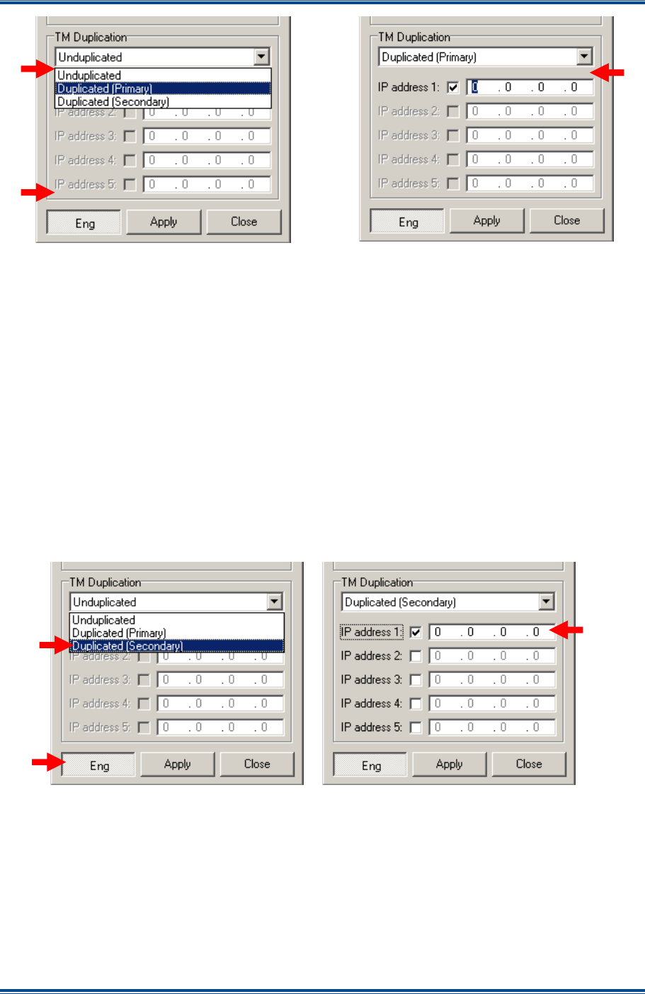
SGD-SB2025NT-TUM, Part 2
Jan 12 Page 73
DIAGNOSTICS
Figure 63. Setting for Duplicated (Primary).
Note.
If an IP address is entered that is the same as one already actively in use anywhere on
the TM this will be cleared back to 0.0.0.0 when ‘Apply’ is clicked.
The ‘Duplication Status’ text will now change to reflect the duplication setting and the colour of the
indicator will show the status – see
Section 8.2.4
below.
8.2.3 Duplicated (Secondary)
This option specifies that this TM will be operating in a duplicated environment and that it is
designated as a Secondary TM.
To configure a TM to operate as a Primary, carry out the following:
1. Open the TM Status panel and select the ‘Network’ button (see
Section 4.3 – Setting the
TM IP Address
). The ‘TM Network Setup’ page shown below in part in
Figure 64
will open.
Figure 64. Setting for Duplicated Secondary.
2. On the ‘TM Network Setup’ page, carry out the following:
2.1. Select the ‘Eng’ button.
2.2. Using the drop-down list, set the TM Duplication to ‘Duplicated (Secondary)’.
2.3. Tick the ‘IP Address 1’ box, which is now active.
2.4. Enter the IP address of the first Primary TM.
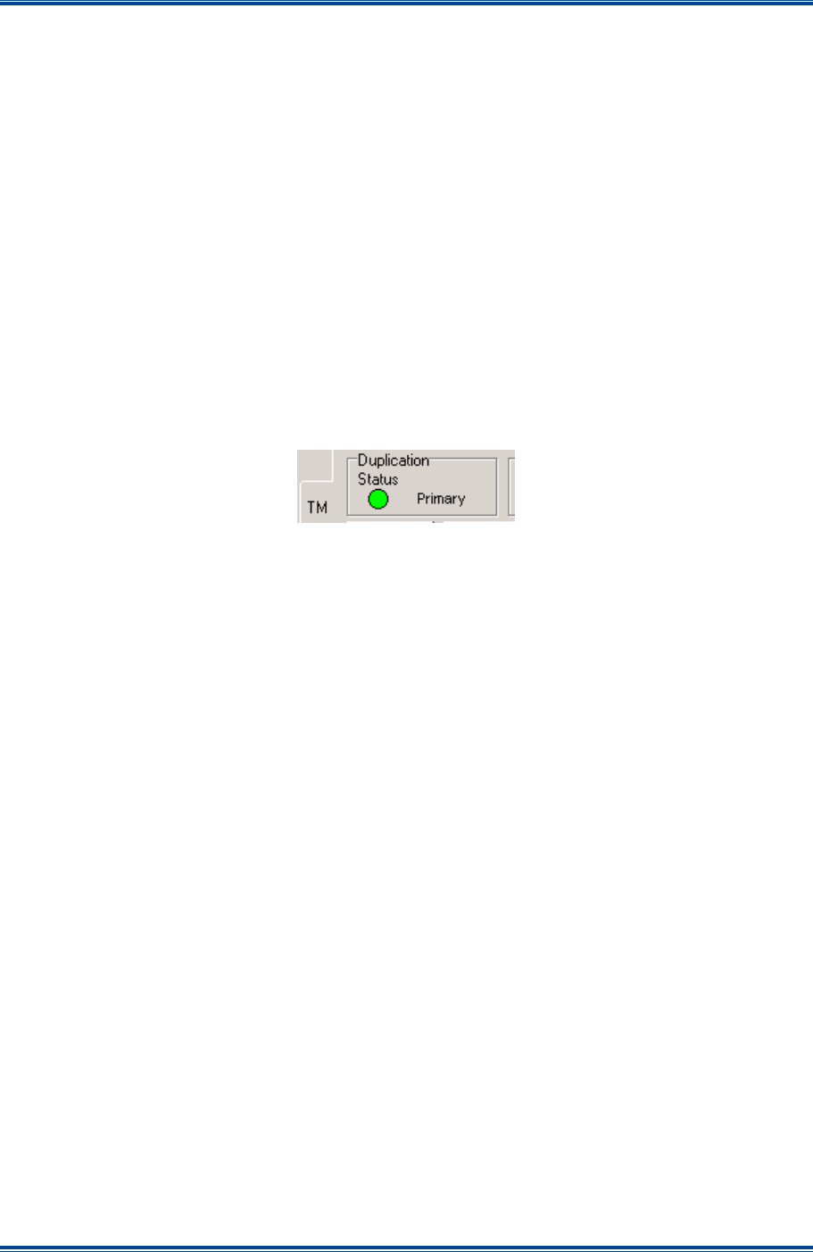
SGD-SB2025NT-TUM, Part 2
Jan 12 Page 74
DIAGNOSTICS
2.5. Repeat Paras 2.3 and 2.4 for any further Primary TMs but ticking ‘IP Address’ box 2, 3
etc in order of their priority.
2.6. Select the ‘Apply’ and then the ‘Close’ buttons.
Note.
The IP address table also reflects the priority order in which the Secondary TM will
take over from the Primary TM (highest priority is position 1, lowest priority is
position 5).
The ‘Duplication Status’ text will now change to reflect the duplication setting and the colour of the
indicator will show the status – see
Section 8.2.4
below. Once the Secondary TM is configured
and connected to the network it will quickly gain the configuration(s) from the Primary TM(s) and be
ready to operate as hot standby.
8.2.4 Duplication Status
The text alongside the Status indication on the TM Status panel will show ‘Primary’ or ‘Secondary’
according to the duplication configuration.
Figure 65. Duplication Status Indication.
Confirmation that Primary and Secondary units are operating and in communications with each
other is shown by the ‘Duplication Status’ indicator going
Green
; loss of communications will cause
the indicator to turn
Red
on both units. A
Red
Status indication does not necessarily mean that the
other TM has failed but that there is no information exchange between units. This may result from
unit failure or a network problem. However, in the case where the Secondary TM has taken over
from another Primary TM since it no longer is able to offer support to those of a lower priority, the
Secondary TM will cease communications with those units causing a
Red
Status indication to be
displayed on each.
The Status indicator may be assigned ‘Alarm’ status although an unduplicated TM will never show
a
Red
Status indication; see
Section 12 – Alarms
.
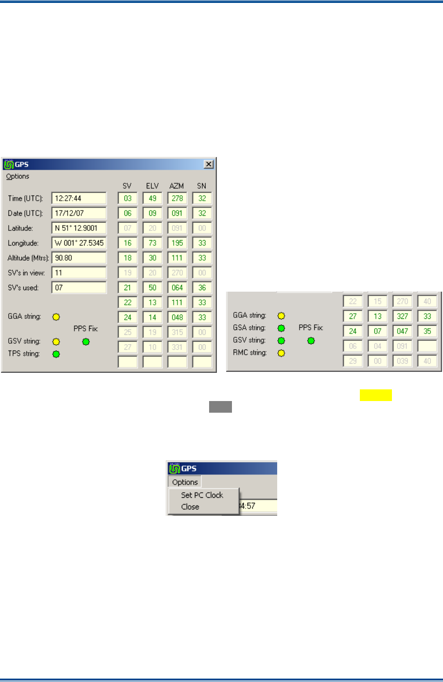
SGD-SB2025NT-TUM, Part 2
Jan 12 Page 75
DIAGNOSTICS
9 DIAGNOSTICS AND OTHER INFORMATION
9.1 GPS
If a GPS Rx is used to provide the 1PPS timing signal, it is likely that NMEA data will also be
supplied. Information is taken from the NMEA data stream about the GPS Rx and displayed on the
satellite signal report page. The ‘GPS’ button on the NI ET and the TM ET provides access to this
page, which is designed to assist in the installation and any subsequent diagnostics of the GPS
Rx. The page is identical in look and operation for both types of ET. Whilst part of the equipment
configuration is to define whether or not NMEA data is present (see
Section 5.3.2.2 – GPS
Module
), the information will always be displayed when NMEA data is connected, i.e. irrespective
of the setup configuration.
Figure 66. Satellite Signal Report.
With the exception of the ‘PPS Fix’ indication, the indicators will flash
Green
/
Yellow
to confirm
correct operation. If all indications remain
Grey
then no data is being received and further
investigation will be required.
The “string” information may differ with early models of GPS Rxs:
Figure 67. GPS Options menu.
Through the ‘Options’ menu it is possible to use Universal Time Coordinated (UTC) time from the
GPS Rx to ‘Set PC Clock’ of the PC running the ET application. This automatically takes into
account the world time zone setting of the PC. The other option is to ‘Close’ the GPS page.
9.2 F
ACILITY
K
EY
The ‘Facility Key’ is a hardware element of the TM programmed and fitted in the factory that
determines the options available. Correct operation of the ‘Facility Key’ is indicated in the area of
the TM Status panel (part shown below).

SGD-SB2025NT-TUM, Part 2
Jan 12 Page 76
DIAGNOSTICS
Figure 68. Facility Key information.
There are three aspects of information displayed about the Key:
(a). ‘
Serial #
’. This is the unique number for the ‘Facility Key’ and ties it to the original supply.
(b). ‘
ID
’. This is a short text string that outlines the facilities enabled by the Key.
(c). ‘
Status
’. This indicates the status of the ‘Facility Key’ and will show
Green
when working
correctly or turn
Red
under a fault condition. This will be accompanied by the text:
(i).
Failed
. The ‘Facility Key’ is now not working correctly having previously been working.
(ii).
Not Found
. The ‘Facility Key’ has not been detected at start-up.
The ‘Facility Key’ Status may be assigned “Alarm” status, see
Section 12 – Alarms
.
9.3 C
HANNEL
V
IEW
F
ACILITY
Although this facility is closely linked to the ‘Relations’ aspect of a multi-channel TM, it probably
becomes of most benefit during system monitoring or maintenance work.
9.3.1 Normal View
To identify which stations are on which channel, the borders around the Station panels that are
members of the channel group and the corresponding ‘Chn’ tab turn
Green
when the channel
status panel is selected. If the channel has an associated Central NI, the Central NI tab for that
channel group will also gain the
Green
border. Similarly, selection of the Central NI panel will
produce the same indications for the channel group to which that Central belongs. Every Station
panel, whether enabled or not, will be visible at all times.
9.3.2 Channel View
When a TM is operating a multi-channel environment, unless the TM configuration has segregated
the stations on a channel by channel basis, it may not be readily apparent which stations belong to
which channel. This situation becomes most noticeable if the user is trying to monitor the activity
of just one channel and stations on other channels are also active, which serves as a distraction.
9.3.3 Selecting Channel View
To enable channel view mode, on the TM Status panel, select the ‘Chn View’ button (see
Section
3.4.1 – TM Status Panel
). Once this mode is enabled, selection of any channel related item
results in only the NI (Stations and Centrals) that are members of that channel group remaining
visible. Normal operation of those NIs no longer visible continues, i.e. this mode does not affect
operation in any respect, it just changes the view presented on the TM ET.
Examples of Channel view mode are shown overleaf in
Figure 69
.
9.3.4 Returning to Normal View
Reselecting the TM Status view will cause all station panels to become visible as no channel
specific item is selected. To return fully to this view, release the ‘Chn View’ button on the TM
Status panel.
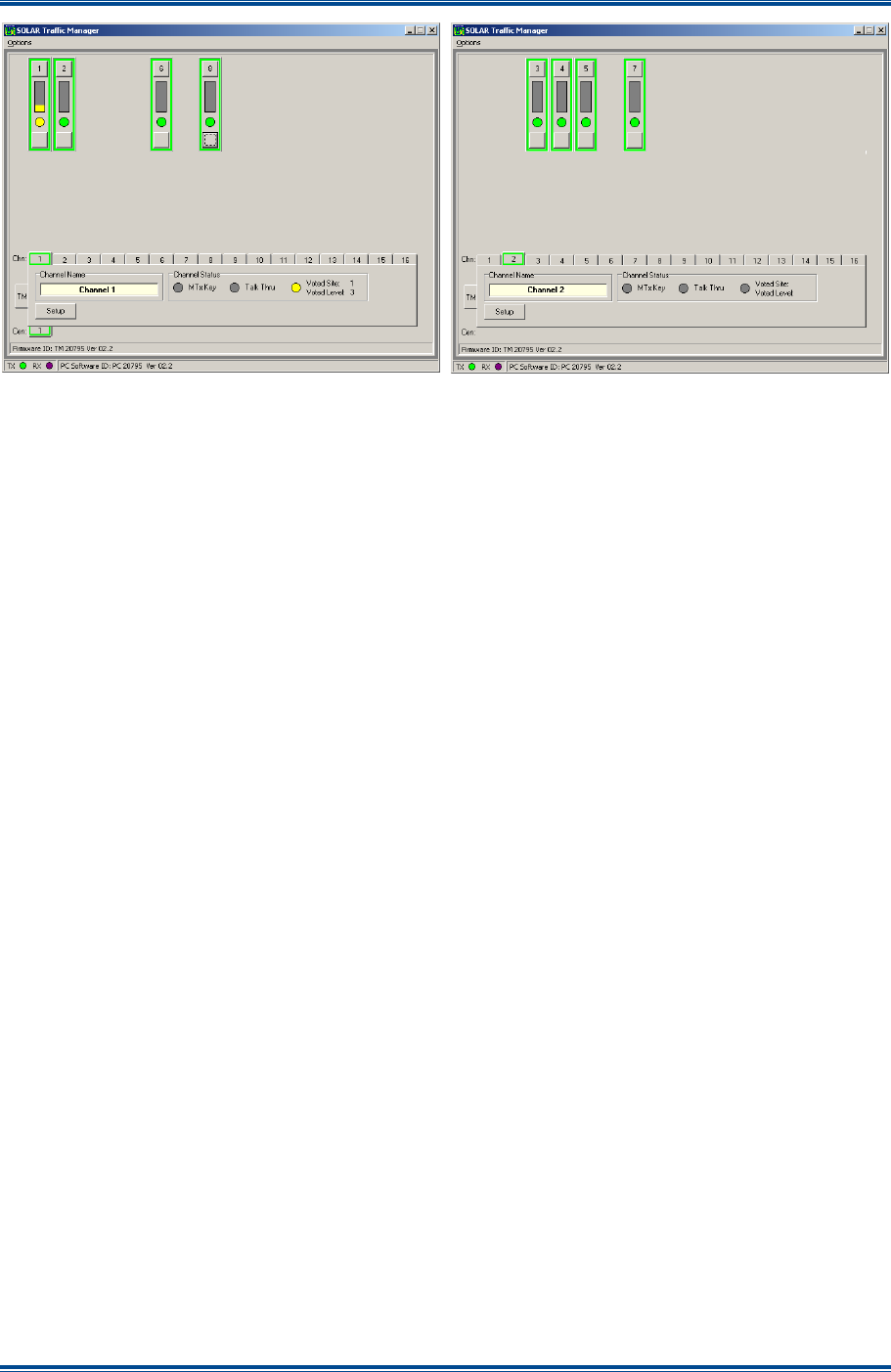
SGD-SB2025NT-TUM, Part 2
Jan 12 Page 77
DIAGNOSTICS
Figure 69. Examples of Channel View Mode.

SGD-SB2025NT-TUM, Part 2
Jan 12 Page 78
RECEIVER VOTING
10 RECEIVER VOTING
10.1 V
OTING
O
VERVIEW
The process of selecting the best signal from a collection of signals that are being returned from
several Station NIs at remote radio sites is commonly referred to as “Voting”. This terminology will
be used throughout this section.
The voting process takes place in the TM unit at a digital level. In order that the TM can make a
selection of the best incoming signal, information needs to be available on which the voting
process can operate. That information is produced by the Station NI and, upon receipt of that
information, the TM will make a comparison of the value that is being returned from every active
site and, subject to criteria, select the site delivering the highest value.
10.2 S
IGNAL
Q
UALITY
I
NFORMATION
Each and every Station NI will produce a value representative of the quality of any signal
originating from the co-sited base station Rx.
The source of this signal can be in one of two formats:
• Signal strength reading as an analogue voltage (RSSI).
• Variable tone representing the RSSI (either continuously variable or stepped).
The analogue voltage RSSI is taken to a dedicated input on the facilities connector, whereas the
variable tone is taken from the audio input that is being produced from the base station Rx.
Whatever the signal source selected (a user configurable feature), it is turned into a number that is
compared to preset boundary values (also configurable parameters), which define the minimum
threshold of operation and govern the range and resolution of the reported signal quality level. A
hard-wired signal indicating receiver mute open (COR) may also be used. The configuration
values of these parameters are likely to be the same at every radio site and that is a good way to
achieve initial setup. Subsequently, these may well be varied to suit individual site conditions, e.g.
sites with high background noise levels.
A value representing the signal quality is added to the packet of data containing the radio traffic
itself and passed back to the TM every 20 ms. This information is treated as a high priority part of
the Solar supervisory and signalling data subset information within the IP data packet.
10.3 V
OTING
P
ROCESS
For each NI, the RTN traffic audio packets are assigned to slots in a queue (a buffer) according to
the packet number. This action ensures that the packet order is correct, so that when the Voter
process compares the RSSI of packets at the head of the queue they will all have the same time of
origin (the input from main Rx to Station NI). As this is done for every NI at the same time,
synchronisation of the RTN audio is achieved.
The Voting process consists of looking for the mute open status within each packet and extracting
the RSSI value if appropriate. The RSSI values for each active site are then compared and the
packet from the site offering the highest value is passed to the Central NI for decoding. Once a
site is selected, a site offering a higher RSSI value must exceed the current RSSI value of that
from the selected site by the ‘Voter Level Difference’ parameter before a change in selection will
occur.

SGD-SB2025NT-TUM, Part 2
Jan 12 Page 79
RECEIVER VOTING
As this process is undertaken for every packet, the voting response time is 20 ms. Since the IP
data packet contains both the RSSI information, the digitised audio and simultaneously conveys
the fact that a signal is present, no audio will be lost at the start of an incoming signal due to the
delay whilst the voter makes a signal assessment. The latter situation is common with
conventional analogue voting systems as the audio is already being presented before the voter has
made a selection.
10.4 V
OTER
C
ONFIGURATION
The Firmware configuration table contains variable parameters that control the action of the Voting
process based on the Signal Quality information. These parameters have a range of movement
which may include the OFF state; they can be adjusted to give optimum performance to suit the
operational conditions.
10.4.1 Voting Parameters
The configuration table state is non-volatile and is accessed indirectly via the ET.
Table 4. Voter Adjustable Parameters.
Function Range
Level of difference in RSSI necessary before a selection
change is made. 1 to 13 in unity steps.
Deselect and ignore a site that has had mute open for x
(time). Return the site to voter availability when it’s mute
closes for a minimum of 10 seconds (not configurable).
Range OFF or x = 5 min to 30 min
in 5 min steps.
Voter Override – a means to force the selection of site x
irrespective of the incoming RSSI.
Range OFF or x = 1 to 32 – only
enabled slots may be selected.
10.5 B
EST
S
IGNAL
S
ELECTION
–
P
ARAMETERS
This relates to the measurement units used by the integrated Voting algorithm of the NI.
10.5.1 RSSI
An output is required from the base station Rx in the form of a varying voltage or a variable tone
that is input to the Station NI.
Table 5. RSSI Requirements.
Function Range
Voltage RSSI:
Voltage Input Range >0 V and <5 V DC
Conversion Resolution 14 steps
Conversion Settings
The minimum and maximum values of RSSI input are entered as
boundary values. A minimum value of zero will disable the function.
A value exceeding the maximum will not increase the RSSI further.
Tone RSSI:
Tone Input Range 2.6 kHz to 3.5 kHz – user definable.
Conversion Resolution 14 steps – equally spaced in tone range

SGD-SB2025NT-TUM, Part 2
Jan 12 Page 80
RECEIVER VOTING
10.6 S
QUELCH
I
NPUT
(COR)
This is an optional input condition, since the RSSI input itself can be used to determine that the
receiver is active once the input signal has reached the minimum boundary value. However, use
of this input is strongly recommended to prevent false voting states if an RSSI voltage is used.
This condition can often occur, as the RSSI voltage output is likely to rise when invalid signals are
received (incorrect or no CTCSS) or from high level close frequency signals such as adjacent
channel interference.
To use this input for the “Squelch” or “COR” state requires that ‘Isolated Input #1’ be assigned to
‘Auto’ in the Setup configuration of the NI (see
Section 5.2.2.4 – Isolated Inputs
). It is activated
by the application of a ground (0 V) to the input and when the RSSI signal from the receiver is
equal to or exceeds the minimum defined level the voting encode process will commence; i.e. Rx
squelch
AND
the minimum RSSI level are both required.

SGD-SB2025NT-TUM, Part 2
Jan 12 Page 81
TROUBLESHOOTING & MAINT
11 ET TROUBLESHOOTING AND MAINTENANCE
11.1 N
ETWORK
L
ATENCY AND
F
AULTS
The crucial parameters in the successful operation of Solar are the buffer times, which are set in
the ‘Sync Timing’ page of the TM ET (see
Section 7 – Solar (Sync) Timing
for details). Making
the buffers unnecessarily large will undoubtedly mean the Solar network will function but will
introduce noticeable end-to-end audio delay especially for T/T operation. It is far better to optimise
the settings to match the characteristics of the network. In order to do that requires an
understanding of the effects that can result from network issues; these are examined in the
following sub-sections.
11.1.1 Packets Arriving Late
Data packets that arrive outside of the allocated time window will be discarded. If this situation
occurs infrequently, the effect is highly unlikely to be noticed. However, if the packet loss rate
increases to a significant number, the glitches in recovered audio signal will become apparent,
necessitating an increase in the overall time allocation or a examination of the network quality or
both. If a problem occurs that causes every packet to arrive outside of the time window, the NI will
not function, i.e. neither the audio nor the signalling will be output. The NI reports lost packets on
the Setup Info page (see
Section 2.4.1.4 – Pkt Errors
).
11.1.2 Network Re-routing
One of the biggest advantages of using IP networks is the possibility to quickly re-route ‘traffic’
around a fault condition. Traditionally, this is not something that a conventional simulcast system
could easily manage, due to the change in audio characteristics that inevitably results from
changing a bearer circuit. As Solar is transported entirely at IP level, then, subject to its operating
limits, Solar is able to make good use of the network re-route feature and provide a level of
resilience not available to conventional simulcast systems.
It is quite reasonable to assume that, when a network route change occurs, the network latency or
packet delivery times to one or more NI will also change. If this results in an increase in time, the
buffer time(s) allocated could prove to be insufficient. This could easily be manifest as
performance degradation on a Solar network that has been operating perfectly up until the point
when a network re-route occurs.
Consequently, it is most important that all potential re-route conditions are carefully examined at
the commissioning stage and the effect on packet delivery times are noted, which will probably
require manually forcing a re-route to occur and analysing the effect. Once the “worst case”
situation has been identified, i.e. the one that reports the longest network delivery times, these
figures should be used to set the ‘Sync Timing’ parameters on the TM.
11.1.3 TM Duplication
If a duplicated TM configuration is to be used, then, as discussed briefly in
Section 8.1.1
, there is a
clear benefit in not locating both Primary and Secondary units together. If this approach is
adopted, there are two situations that must be considered:
(a). The network latency time between any given NI and each TM could be quite different.
(b). A network fault could result in loss of communications between the TM even though each TM
is operating normally.

SGD-SB2025NT-TUM, Part 2
Jan 12 Page 82
TROUBLESHOOTING & MAINT
11.1.3.1 Delay from NI to each TM
The Solar network settings are held in the Primary TM and passed, in their entirety, to the
Secondary TM, i.e. there is no provision to “customise” the Secondary TM in any way. Depending
upon the network “distance” between the two TMs, it is quite reasonable to expect that some NIs
will be ‘closer’ to the Primary than the Secondary and vice-versa.
If buffer settings are used that are simply taken from the results obtained from the Primary TM,
albeit that this is the best way to get the system operating at the initial commissioning stage, when
TM changeover occurs, it may be found that system performance degrades. Therefore, it would be
very easy to conclude that there is some sort of malfunction with the Secondary TM when in fact
the real reason is more subtle.
Therefore, when it comes to optimising the Solar buffer times on a duplicated configuration, the
packet delivery times must be examined when each TM is operating and the “worst case” values
used. If a duplicated configuration is used together with network re-routing, the permutations of
configurations will probably become considerable. However, unless the network architecture is
very complex, it should prove relatively easy to identify what is likely to be the worst case situation
and study that in detail in order to arrive at the optimum buffer settings.
11.1.3.2 Network Fault causing TM Changeover
Similar to the situation with a network re-route, a network failure could result in loss of
communications between the Primary and Secondary TM while both units are working normally.
This will result in the Secondary TM sending data packets to every NI while the Primary TM is still
active. Since we are assuming a fault condition that is preventing inter-TM traffic flow, it would not
be possible for any single NI to “see” both the Primary TM and the Secondary TM at the same
time, i.e. the NI would only receive packets from one TM. This would cause a “split” of the NIs
between the two TM.
The network design and the location of the fault determine which NI would be associated to which
TM. This could range from the Central NI for the channel being on one TM and all the Station NIs
being on the other TM to just one Station NI being “lost” to the Secondary. In the first scenario, the
setting ‘TM triggered Talk Thru’ ‘On Central NI Fail’ (see
Section 5.4.2.4
) would be recommended
so that the channel could still provide a fallback service when running on the Secondary TM. This
setting would of course have to be applied at the Primary TM even though the facility may not
seem appropriate when operating in that mode.
The results of network problems when using a duplicated TM configuration may be very varied but
should be entirely predictable if each fault scenario is carefully considered, even though there may
be little or nothing that can be done about the resultant effects.
11.2 F
IRMWARE
U
P
-I
SSUES
11.2.1 Availability
The latest Firmware version is posted on the Team Simoco web site; users who are on a list of
interested parties will be notified when a new version becomes available.
11.2.2 Loader – General
To up-issue the TM Firmware and NI PIC Firmware requires the use of the ET or ‘Loader’ software
applications. The Loader software is available from the Team Simoco website and, like the ET, is
an executable file, which uses the front panel USB port – it is possible to change firmware remotely
with the ET, however, the Loader application needs a direct USB connection.
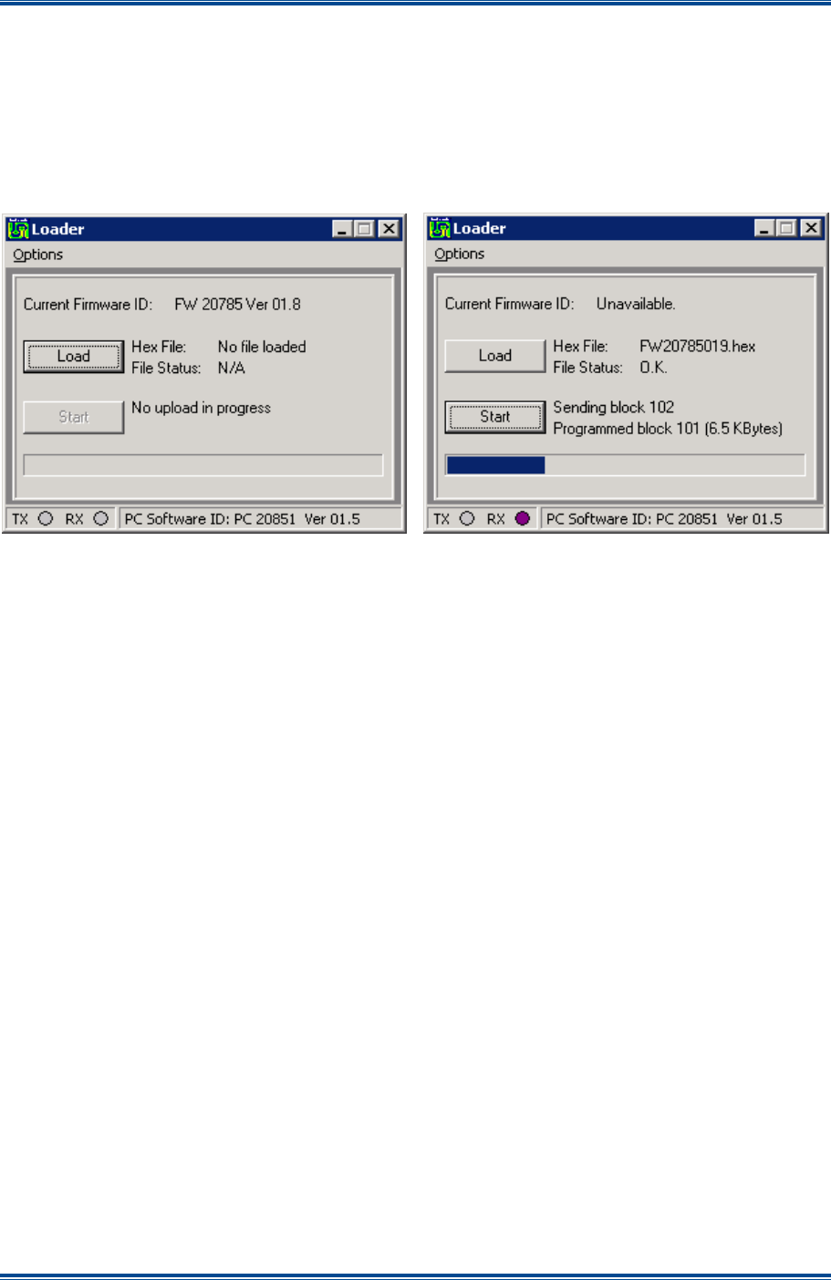
SGD-SB2025NT-TUM, Part 2
Jan 12 Page 83
TROUBLESHOOTING & MAINT
Note.
The ET cannot be used at the same time as the Loader software as they use the same
com port on the equipment.
Run the Loader application and “Connect” to the equipment in exactly the same way as for the ET.
Follow the help guidelines for using the ET in
Section 1.3
. The current Firmware version will be
reported once the connection is established.
Figure 70. Loader Application.
On the Loader application window, select the ‘Load’ button and an Open file window will be
displayed from which the folder and file may be selected; only filenames with the ‘hex’ extension
will be displayed. Navigate to and select the correct file and, on the Open file window, select the
‘Open’ button to prime the file loading. On the Loader application window, select the ‘Start’ button
to commence loading the selected file. The progress bar indicates the time to completion.
11.2.3 Traffic Manager
The TM will continue to operate normally during an up-issue. When the firmware upload is
complete the TM will restart automatically and will be running the new software within a few
seconds. Occasionally, adding new features will necessitate changing the format of the stored
configuration data, therefore, the existing stored data may not match the requirement of the new
firmware and, consequently, may need to be re-entered using the ET application. If this is going to
be necessary, suitable notification will be given in the Engineering Bulletin that accompanies all
software releases.
If operating a Solar network with duplicated TMs, it is essential that both TMs are upgraded to the
same software version. During the upgrade process it would be prudent to ensure that only one of
the TMs is operating at a time. This will prevent the situation arising when both TMs try to run the
network, which might occur after the first TM is upgraded and before the second TM is brought up
to the same version of software. Again, suitable advise of the potential for this situation arising will
be provided in the associated Engineering Bulletin.
11.2.3.1 Invalid TM firmware
When a new firmware file is offered to a TM, the TM will check the file to ensure that it is valid TM
firmware and a file that fails this check will be rejected. This check is very comprehensive so it
would be extremely unlikely that an invalid file would be loaded. Once the file check test has been
passed, the loading process will commence and each byte is checked against a checksum and
again once the whole file is loaded. Only at this stage would the file be used to replace the existing
firmware.
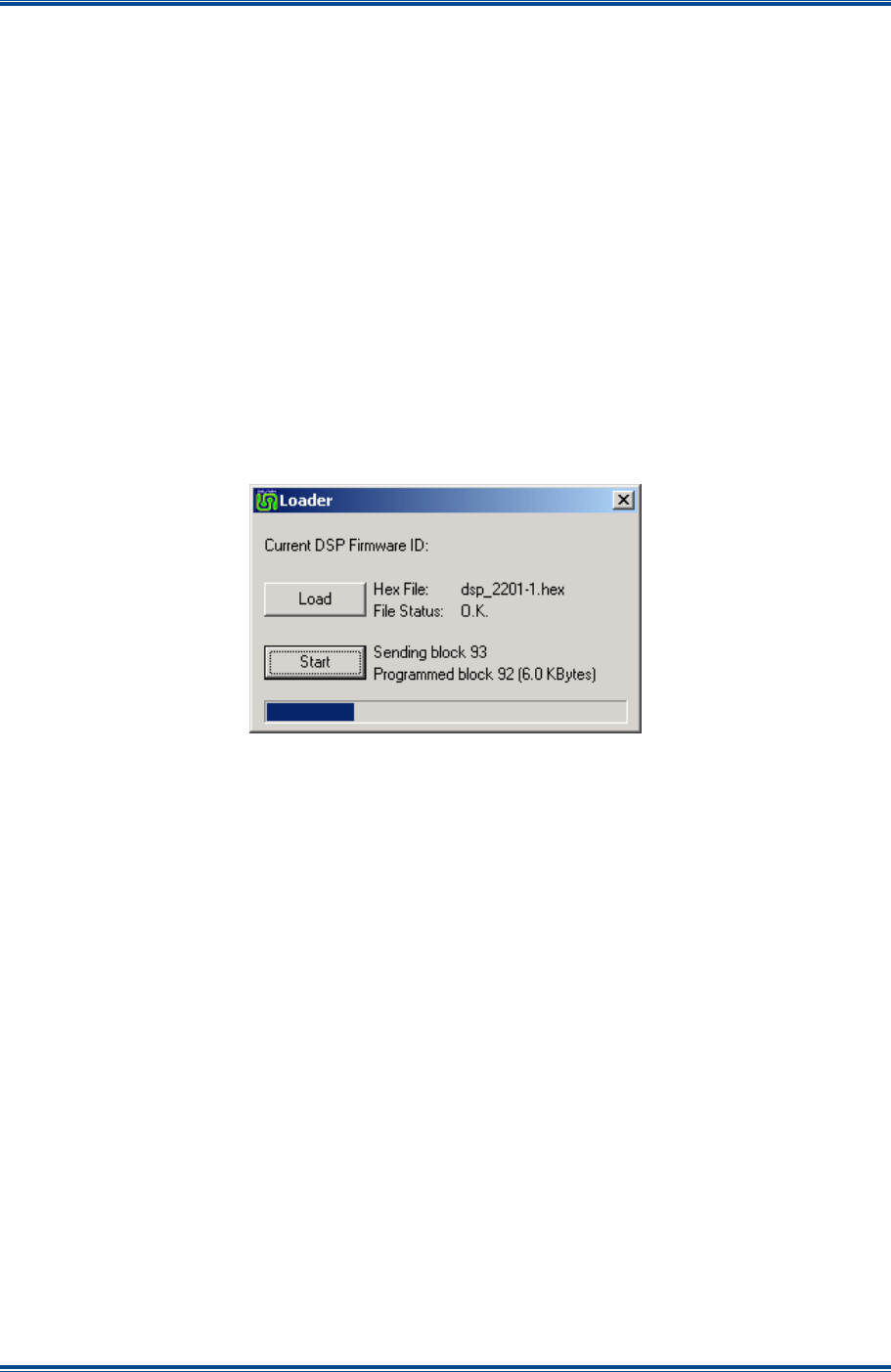
SGD-SB2025NT-TUM, Part 2
Jan 12 Page 84
TROUBLESHOOTING & MAINT
If circumstances should somehow arise that results in the firmware file being corrupted, although
the TM will not operate normally, it will run a special fall back program to allow the ‘Loader’ to be
connected so that replacement firmware can be loaded.
11.2.4 Network Interface
The NI will suspend normal operation during an upgrade. There are two Firmware programmes in
the NI:
(a).
PIC Firmware
. This is the main unit operating process and is changed using the Loader
application as detailed above.
(b).
DSP Firmware
. Digital Signals Processor (DSP) Firmware is changed using a function
integral to the NI ET.
11.2.5 NI DSP Firmware Up-issue
A DSP Firmware up-issue is executed by selecting the ‘DSP’ button of the NI ET (see
Section 2.6
). This runs the Loader application from within the ET, which is used in exactly the
same way as for the NI PIC Firmware itself.
Figure 71. NI DSP Upgrade.
On the ‘Loader’ application window, select the ‘Load’ button to open a standard Open file window.
On the Open file window, locate the appropriate DSP ‘hex’ file and select the ‘Open’ button to
prime the file for loading. On the Loader application window, select the ‘Start’ button to instigate
the upload process. The progress bar indicates the time to completion.
The NI will automatically restart following a DSP upgrade and the new firmware version will be
reported in the DSP loader sub-window and on the bottom bar of the ET main window. Close the
DSP loader sub-window with the
(close) icon (top right).

SGD-SB2025NT-TUM, Part 2
Jan 12 Page 85
ALARMS
12 ALARMS
12.1 A
LARMS
O
VERVIEW
The alarms facility of Solar is a useful feature especially for the smaller systems. It is designed to
alert the user by means of an alerter device connected to a Central NI to a situation designated as
requiring attention. Configuration of the alarms facility and any subsequent analysis into the nature
of an alarm requires use the TM ET and, therefore, is not recommended for use by non-
engineering staff. Whilst alarms may originate from a NI, the NI does not generate the alarm
condition. It is the report of a state change (an event) from a NI to the TM, as part of the normal
supervisory process, which will cause the TM to raise an alarm if that event has been so
designated, i.e. the alarm process lies entirely within the TM domain.
On larger systems or for more comprehensive system monitoring, the use of SNMP is strongly
recommended. SNMP will provide control of many aspects of a Solar network as well as being
able to take/accept user definable fault conditions. Full information on SNMP is provided in
Section 14 – SNMP
.
12.2 A
LARM
F
UNCTIONALITY
There are a number of designated events in a NI and a TM that may be selected to operate as
alarm initiation events. When an event is selected and that event is active, a flashing
Red
indication will be displayed on the ET to alert the user to the presence and source of the alarm.
An external indication of an alarm being active can be obtained from the ‘Isolated Output #2’ on a
Central NI when it is set to operate in the ‘Auto’ mode. The alarm condition will then operate that
relay in the Central NI for the channel that is exhibiting the alarm. If the alarm is from the TM itself
making it channel independent, ‘Isolated Output #2’ will be activated on every Central NI
configured for an alarm output.
12.3 A
LARM
S
ETUP
(TM
ET
O
NLY
)
Although the majority of alarms are likely to originate from NI, there is no facility to alter or examine
the alarm settings from the NI ET, as the alarm settings are managed and maintained by the TM
from the status information passed to the TM through the supervisory sub-system. The events that
may be selected to generate the alarm condition are set on a unit by unit basis through the
engineering facility.
Events that can be configured to generate an alarm condition are selected by opening the ‘Alarms’
page (the ‘Alarms’ tab) of the item and selecting the event(s) as required from the following:
(a). Environment Inputs – ‘Environment’ page.
(b). Isolated Inputs (NI only) – ‘Signalling’ page.
(c). Network Status, 1PPS Status and PLL Status – these comprise the ‘Misc Alarms’ on the
‘Facilities’ page of the NI.
(d). Duplication Status, 1PPS Status and Facility Key Status – these comprise the ‘Misc Alarms’
on the ‘Facilities’ page of the TM.
Before any change or selection can be made, the ‘Eng’ button must be selected and the ‘Apply’
button used to confirm the selection.
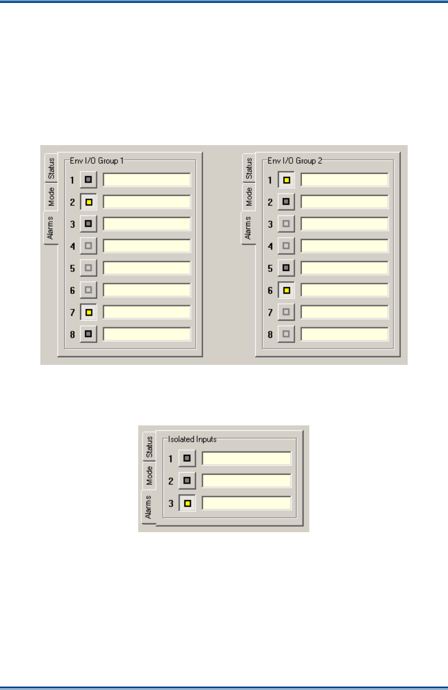
SGD-SB2025NT-TUM, Part 2
Jan 12 Page 86
ALARMS
12.3.1 Environment Inputs
Each of the environment inputs may be selected to generate an alarm whenever that input is taken
to an active state. As each on the sixteen connection points may be defined as an input or an
output, only those defined as inputs are available to assign to an alarm; those defined as outputs
do not support the alarm facility as shown by the button being unavailable.
As an example,
Figure 72
below shows that points 4, 5 and 6 in Group 1 and 3, 4, 7 and 8 in
Group 2 have been defined as outputs making them unavailable to be assigned to the alarm state.
The remaining points have been defined as inputs and, of these, 2 and 7 in Group 1 and 1 and 6 in
Group 2 have been assigned to alarm status.
Figure 72. Setting Alarms for Environment Inputs on a NI.
12.3.2 Isolated Inputs
As an example,
Figure 73
below shows that ‘Isolated Input’ #3 has been assigned to alarm status.
Figure 73. Setting Alarms for Isolated Inputs on a NI.
12.3.3 NI Misc Alarms
As an example,
Figure 74
overleaf shows that ‘Network’ and ‘PPS’ have been assigned to alarm
status.
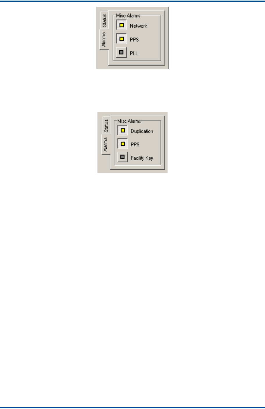
SGD-SB2025NT-TUM, Part 2
Jan 12 Page 87
ALARMS
Figure 74. Setting Misc Alarms for a NI.
12.3.4 TM Misc Alarms
As an example,
Figure 75
below shows that ‘Duplication’ and ‘PPS’ have been assigned to alarm
status.
Figure 75. Alarms Setup for a TM.
12.4 A
LARM
I
NDICATIONS
12.4.1 Alarm Active
The presence of an alarm condition will be indicated by one or more flashing
Red
borders on the
area(s) of the TM ET main window to indicate the source of the alarm(s). For a Station NI, this is
the Station panel; for a Central NI, this is the ‘Cen #N’ tab; and for the TM itself, this in the ‘TM’ tab.
If the origin of the alarm is an NI which will has a channel relationship, then the tab of the channel
group containing the NI with the alarm will also gain a flashing
Red
border. If a panel or tab was
previously selected so that it had a
Green
border prior to the alarm state, then the border will now
flash alternately
Red
and
Green
.
In
Figure 76
overleaf there are two alarms active as indicated by the flashing
Red
borders or
highlights; one is on the TM itself and the other is on Station NI#1. The Station NI#1 alarm is
causing the alarm indication on the Chan #1 tab to appear since it is a member of the Chan #1
group. To determine the exact cause of the alarm, the status view of the unit with the alarm
indication must be examined. For a NI this means clicking the button to open the remote view
window; for the TM this is shown on the TM Status panel.
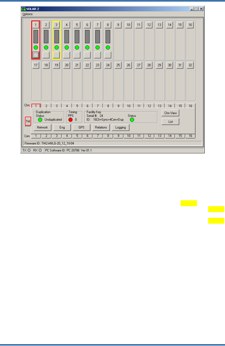
SGD-SB2025NT-TUM, Part 2
Jan 12 Page 88
ALARMS
Figure 76. Examples of Alarm Indications.
12.4.2 Alarm Acknowledge
As an alarm indication will continue to be displayed even if the original event is no longer active,
the alarm may be acknowledged so that the external alarm output, ‘Isolated Output #2’ on the
Central NI, is deactivated. This also serves as a means of recognising if a subsequent alarm
condition occurs before the first has been cleared.
When an alarm is acknowledged, the alarm indication will change to a flashing
Yellow
border if no
other alarms are present on the unit. Once an alarm is acknowledged, the flashing
Yellow
indication will cease immediately if the original alarm event is no longer active or will continue until
that alarm event becomes inactive. Individual status indicators will also adopt the flashing
Yellow
state for the alarm acknowledged condition. In
Figure 76
, Station NI#3 has an acknowledged
alarm and the following figures will show the process of other alarms being acknowledged.
Alarms are acknowledged through the ‘Engineering’ facility for the unit concerned using the ‘Ack
Alarms’ button, which will only become active if an alarm is present on the page in view. If alarms
exist on more than one page, then each page must be acknowledged individually. Only when all
alarms have been acknowledged will the common alarm indication for the unit enter the
acknowledged state.
If alarms are originating from different units, each unit will have to be acknowledged individually. If
multiple alarms are present on a channel, only when all alarms on the channel have been
acknowledged will the external alarm output cease.
The alarm example in
Figure 77
overleaf shows that the TM alarm is due to the ‘PPS’ Status
indicator on the ‘Misc Alarms’ page. The ‘Ack Alarms’ button is enabled and when it is selected,
the alarm indication changes to the acknowledged state and the ‘Ack Alarms’ button becomes
disabled. If a second alarm had been present on the same page, that too would have been
acknowledged.
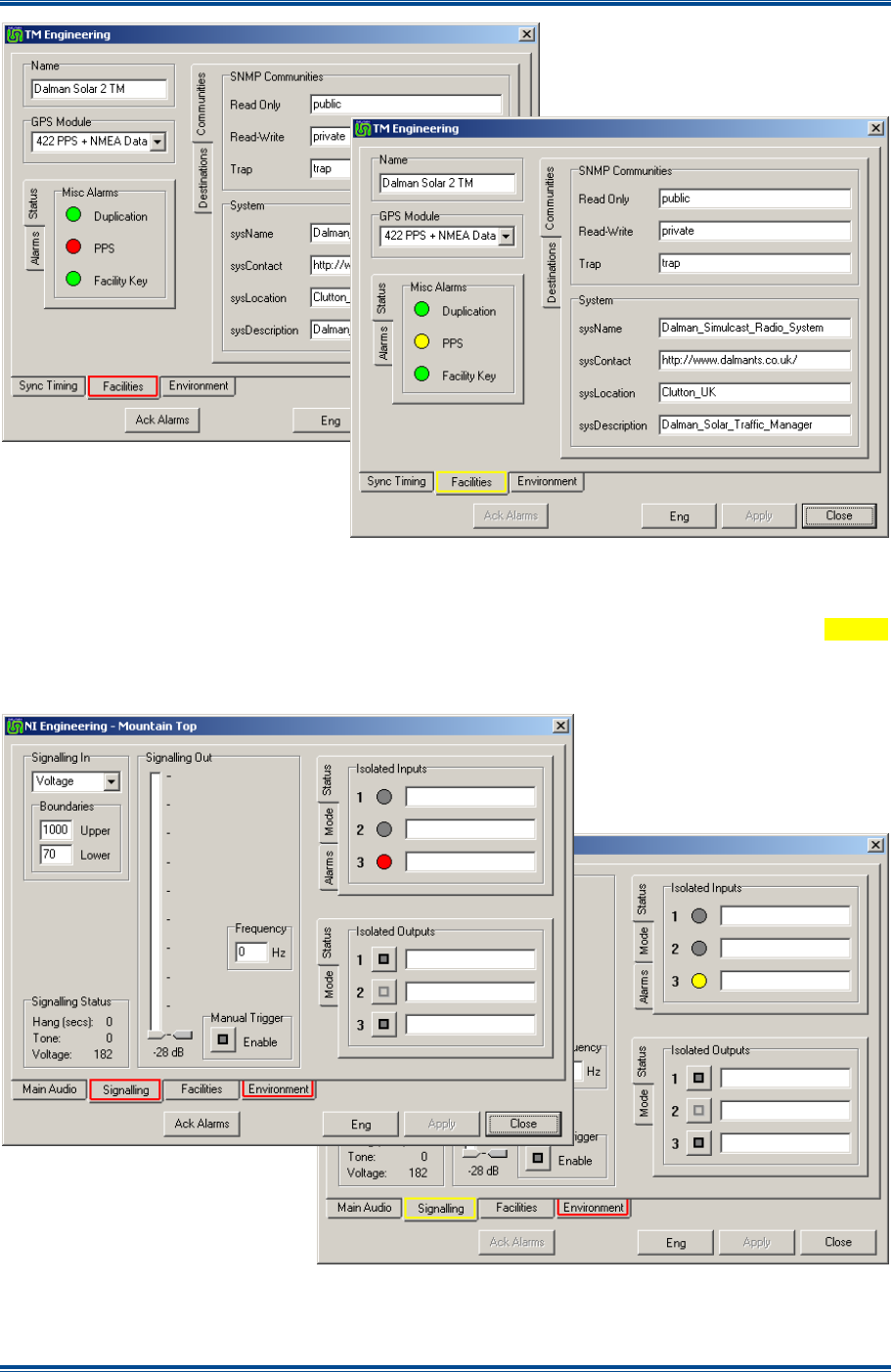
SGD-SB2025NT-TUM, Part 2
Jan 12 Page 89
ALARMS
Figure 77. PPS Alarm on the TM.
The alarm example in
Figure 78
below shows that alarms are present on the NI ‘Signalling’ and
‘Environment’ pages. The ‘Signalling’ alarm is due to ‘Isolated Input #3’ and acknowledging that
changes the flashing border on the ‘Signalling’ tab and the input indicator to flashing
Yellow
whereupon the ‘Ack Alarms’ button becomes disabled. The alarm on the ‘Environment’ page must
be acknowledged separately as shown overleaf in
Figure 79
.
Figure 78. Alarm on the NI Signalling page.
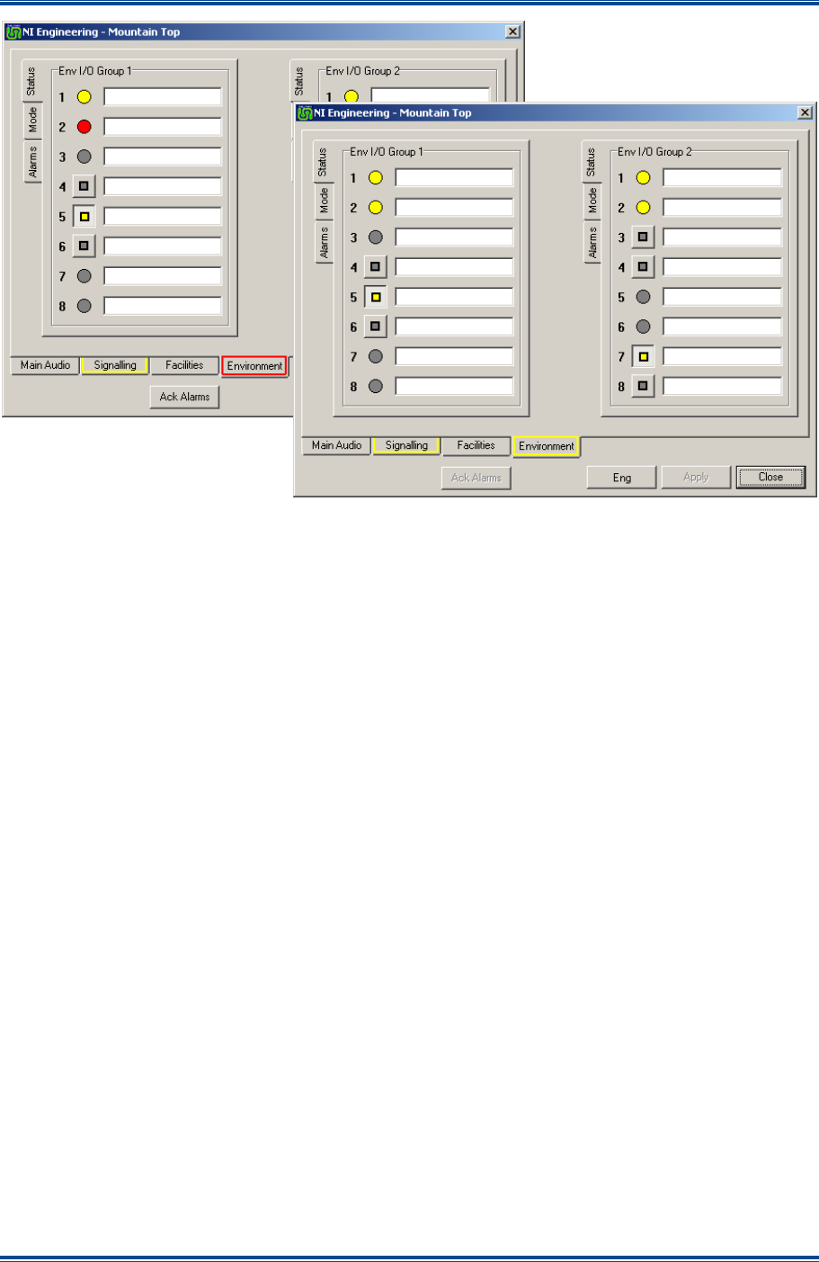
SGD-SB2025NT-TUM, Part 2
Jan 12 Page 90
ALARMS
Figure 79. Alarm on the NI Environment page.
12.5 TM
D
UPLICATION
A
LARMS
12.5.1 Alarms on a Secondary TM
Just as for the other parameters in the Secondary TM, the definition of alarm events will be taken
from the Primary TM; they cannot be different to the Primary TM or defined at the Secondary TM.
However, alarm events must be acknowledged at each TM independently.
When the Primary TM has been configured to generate alarms, if the Secondary TM subsequently
experiences an alarm event whilst offline, it will not have control of the Central NI and, therefore, is
unable to generate the external alarm function to indicate a problem. Similarly, monitoring for
alarms will be conducted through the Primary TM, consequently, an alarm on the Secondary TM
will again go unnoticed.
12.5.2 Indicating an Alarm from an Offline TM
The problem of not knowing of an alarm on an offline Secondary TM is handled by the Secondary
TM ceasing to communicate with the Primary TM. This will cause the ‘Duplication’ fail indication on
the Primary TM to be activated, therefore, it is imperative to ensure that the ‘Duplication’ alarm is
enabled so that the external alarm indication will operate.
If this situation arises, the first action will be to acknowledge the ‘Duplication’ alarm on the Primary
TM and then attempt to access the Secondary TM to examine and acknowledge the alarm. If
remote access to the Secondary TM fails, this will indicate either a total failure of the Secondary
TM unit or a network fault. If access into the Secondary TM is successful, the alarm can be
acknowledged as described earlier and any appropriate action taken.

SGD-SB2025NT-TUM, Part 2
Jan 12 Page 91
ALARMS
12.5.3 Secondary TM Alarm Acknowledged
On acknowledging the Secondary TM alarm, the Secondary TM will resume communications with
the Primary TM resulting in the acknowledged ‘Duplication’ alarm on the Primary TM ceasing.
From that point on, it will not be automatically apparent, that the original alarm on the Secondary
TM has cleared. For example, if the original problem at the Secondary TM was loss of GPS signal
(‘PPS’ fail), once this alarm is acknowledged, the return of the GPS signal will not be notified, i.e. it
will be necessary to log back into to the Secondary TM at intervals to check if the problem is still
present or has cleared. Once the original alarm has been acknowledged on the Secondary TM,
the occurrence of any other alarm or re-occurrence of the same alarm will be notified as described
above.

SGD-SB2025NT-TUM, Part 2
Jan 12 Page 92
TM LOGGING
13 TM LOGGING
13.1 O
VERVIEW
This section describes the TM Logging facility that is an inherent feature of the TM and
independent of all other options.
Information is automatically gathered by the TM; the only setup required is that of setting system
time. The data is stored in four log files, one covering each event subject. These are generated
on a daily basis and are retained for 28 days. Through the TM ET, the information held in any log
file (current or historic) may be viewed by selecting the date and the log subject. The log file view
on the ET also allows the results to be filtered to focus on the specific subjects such as channel,
equipment and type if a specific issue is being analysed.
The SB2025NT has the option to use a compact flash card instead of the usual hard disk drive and
to reduce wear and prevent premature failure the amount of logging is reduced when the CF is
fitted.
Once a log file is transferred to the ET (opened) it may then be saved to a file in “comma separated
values” (csv) format for archiving. This format makes it ideal for transfer to a spreadsheet if a more
detailed examination outside of the ET application is required. The original log files are not
accessible to the user.
13.2 E
VENT
S
UBJECTS
The log files are separated into the four event subjects: Alarms; System; Voter; and ET. A new log
file is created when the first event for that log occurs for that day. If the first event is the TM being
switched on, every log file will start with that entry showing the time the log file was created and the
fact that the TM was started. Subsequent TM restarts or reboots are logged in each file but the full
start-up information is only in the system log.
13.2.1 Alarms Log
For an event to be logged in the Alarm log, that event must be configured to alarm status. Full
information on configuring alarms and their action can be found in
Section 12 – Alarms
. The
occurrence of every alarm event is logged with the information that uniquely identifies the source
and nature of the alarm. The action of acknowledging an alarm is also logged and this action may
or may not have occurred before the status of the alarm item in question has returned to normal.
If the item had returned to normal status before the alarm is acknowledged, the alarm log will show
the alarm cleared immediately after the alarm was acknowledged. If the acknowledge occurs while
the item is still at alarm status, the alarm cleared message will be logged at the point at which the
status returned to normal, i.e. in real time.
13.2.2 System Log
The system log is focussed on recording events and conditions that might impact upon the
operation of the wider Solar network. Events that directly or indirectly involve the TM are logged
even though these might have occurred at a remote Station NI. For example, a record will be kept
of the ‘PPS’ and ‘PLL’ status for every NI, as problems with either item will result in inaccurate
measurement of the PATs, which impact upon the TM. The log will also record the error counts of
frequency and phase for a NI PLL. These are displayed in the style of ‘0Xnn’ for each value,
where “nn” is the error value in hexadecimal notation.
The event field of a system log will have many entries immediately after a TM is restarted. There
will be more than 20 log entries for the TM itself and also one per NI as each unit is enabled and
brought online.
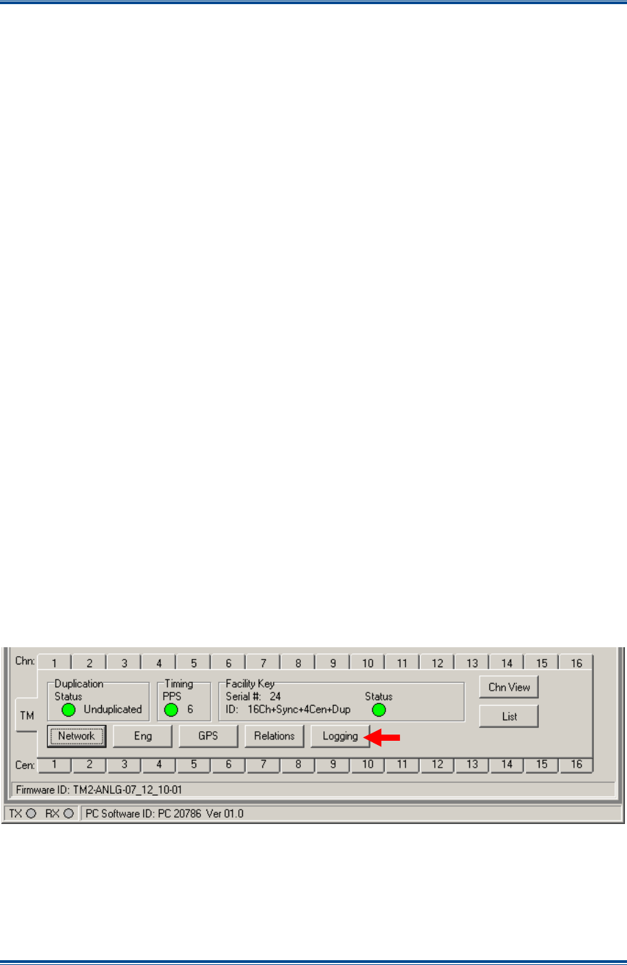
SGD-SB2025NT-TUM, Part 2
Jan 12 Page 93
TM LOGGING
The majority of entries in the system log are likely to be due to automatic functions although an
event might be due to manual action elsewhere on the system.
13.2.3 Voter Log
When a voter change occurs such as happens at the start of an incoming call or a change in voted
site selection or at the end of a call, an entry is generated in the voter log. The information
included with each entry is the RSSI signal level for every site within the channel. This information
is presented as a sub-list in the format of a series of numbers separated by commas such that:
• A value greater than zero represents a site with a valid signal.
• A value of zero represents a site with no incoming signal.
• A null value represents a site that is either not present on that channel or not enabled on the
system.
The full TM capacity of 32 stations is always output in the data field irrespective of the number of
stations on the Solar network. Therefore, it will not be unusual to see a long row of commas
running from Site 1 to Site 32. This approach ensures that opening a log file in a spreadsheet
causes each site to fall into the correct column for each station to ease station identification and
traffic analysis.
13.2.4 ET Log
Connection and disconnection of the TM ET in either serial or network mode will result in an entry
in the ET Log. Actions taken through the ET are also logged but the details of the changes made
will vary according to the nature of the change.
Configuration changes to the TM are logged in full detail as are system configuration changes, e.g.
enabling or disabling an NI, moving a station from one channel to another, changes to an IP
address and changing the alarm configuration of any item. However, engineering changes to an
NI are not logged in detail due to the almost infinite number of variations to audio and tone levels
alone that could occur; these are simply recorded as “Change to Engineering settings”.
13.3 A
CCESS
T
O
T
HE
TM
L
OGS
To gain access to any log related aspect, select the ‘Logging’ button on the TM Status panel to
open the main logging window (still a sub-window on the TM ET).
Figure 80. Route to TM Logging.
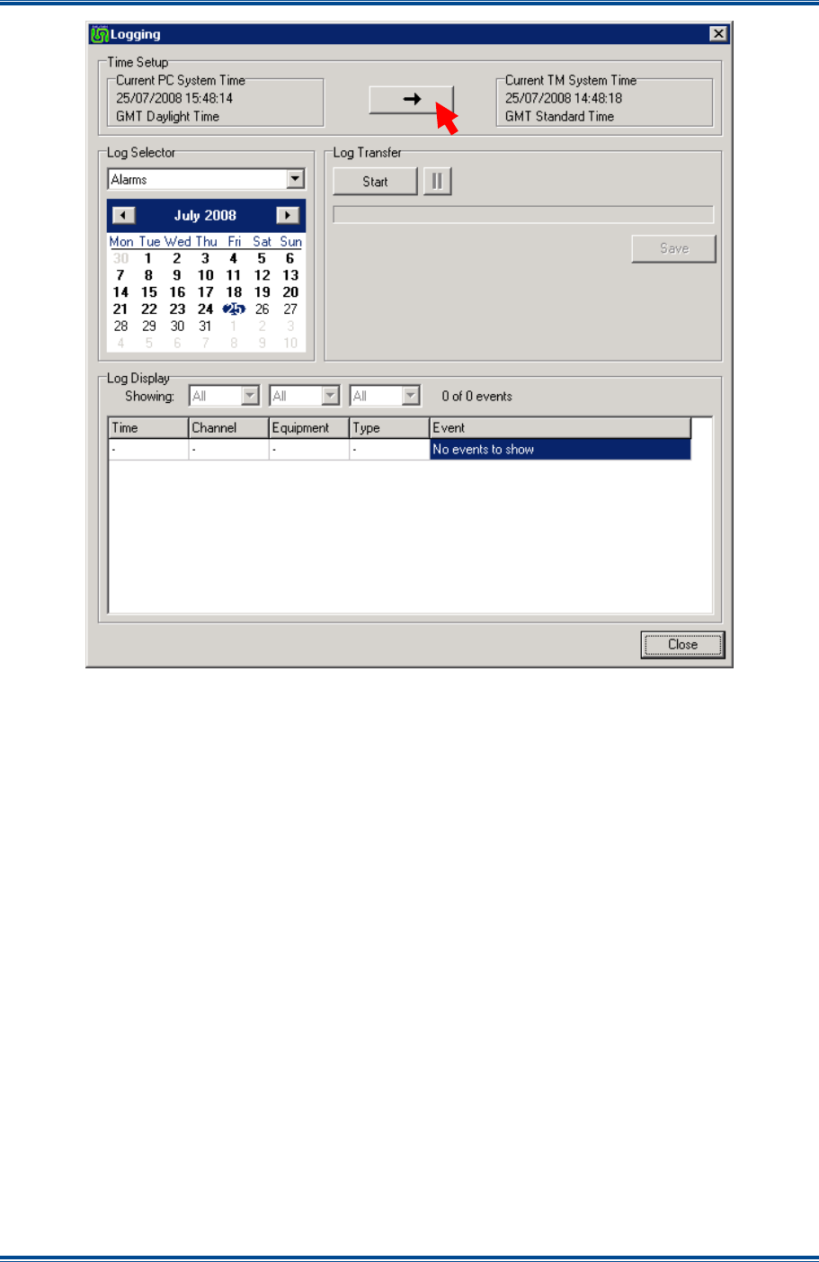
SGD-SB2025NT-TUM, Part 2
Jan 12 Page 94
TM LOGGING
Figure 81. The TM Logging window.
13.4 TM
S
YSTEM
T
IME
TM system time is taken from the TM real-time clock, which will initially need to be configured to
operate in the correct time zone. This information is gathered from the PC hosting the ET
application and the clock will remain aligned to GPS UTC time when this is available with the
appropriate time zone offset. If GPS is not directly connected to the TM, the internal clock may
need to be reset again in the future. The time used in the logs will always be local standard time,
i.e. it is not adjusted for ‘daylight time’ variations.
The four log files created will each normally encompass a 24 hour period of operation of the TM
from 00:00 to 23:59 but will cover a lesser period if the TM is only operating for part of that time.
13.4.1 Setting TM System Time
The TM system clock is automatically synchronised with UTC time from GPS at a “Time Update”
event. However, for a system that does not have a GPS directly connected and therefore UTC is
not available, the TM system clock may be set to that of the PC. To set the TM system time to that
of the PC, select the “Arrow” button in the ‘Time Setup’ panel (see
Figure 81
above).
This time change may be made even if the TM is receiving UTC information, however, the TM
system time will eventually be over-written using UTC when the Time Update event occurs. The
action of setting system time, whether manual or automatic, is itself logged in the system event log
together with the amount of adjustment made.
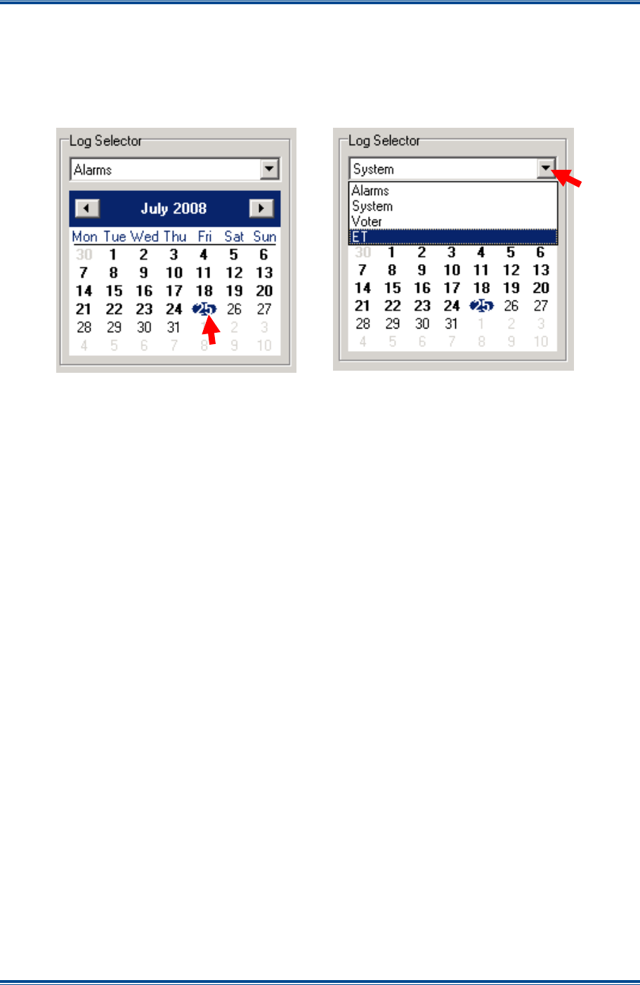
SGD-SB2025NT-TUM, Part 2
Jan 12 Page 95
TM LOGGING
13.5 L
OG
S
ELECTION
Selection of the date of the log to be transferred to the ET is made by clicking on the date required
on the calendar, which will gain the blue highlight; the default selection being the current date.
There is no need to re-select the date if the correct date is already highlighted. The log event
subject is selected from the pull-down list visible above the calendar.
Figure 82. Selecting an Alarm Log.
Dates that fall in the 28 day date range are indicated on the calendar by figures in bold text and
this is most likely to cross the monthly boundary. To select another month, click on one of the
arrow buttons positioned on either side of the name of the month; the button with the left pointing
arrow will move to the previous month and the button with the right pointing arrow will move to the
next month. It is not possible to select a month that would move beyond the twenty-eight day
range.
The fact that a date is shown in bold does not indicate that a log file is available for that date just
that the date lies within the last twenty-eight days. If no activity occurs under a particular event for
that date, no log file will have been created and an attempt to access the log file for that event on
that day will fail as shown by the text ‘No events to show’. This action will itself result in an entry
being logged in today’s system log to show that the log file for that date was not found.
13.6 T
RANSFERRING
T
HE
L
OG
Once the date and log event have been selected, select the ‘Start’ button to transfer the log to the
ET. The transfer may be cancelled with the ‘Cancel’ button or paused at any time using the pause
button, which only becomes active during the transfer process. Depending upon the size of the log
file and the speed of the ET connection (i.e. network or serial), the progress bar will indicate the
rate of transfer. A short log file will be transferred very quickly on a network connected ET
therefore the progress bar may only appear to blink.
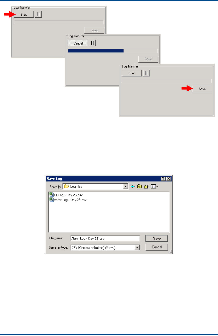
SGD-SB2025NT-TUM, Part 2
Jan 12 Page 96
TM LOGGING
Figure 83. Transferring a Log File to the ET.
13.6.1 Saving the Log
When the log transfer process is complete, the ‘Save’ button will become active and remain active
while the file is present in the ‘Log Display’ area. When the ‘Save’ button is selected, the ‘Save
Log’ file page will open allowing the selection of folder and naming of the log file. The default
filename indicates the type of event log and the date (day), this may be changed as desired
although the file type is always ‘csv’. The file name suggested is not that of the internal log file,
which is not accessible to the user.
Figure 84. Saving a Log File.
If a complete record of system operation is to be kept then saving the log files on a regular basis is
necessary as each internal log file will be deleted after twenty-eight days.
13.6.2 Log Display
Once a log file has been transferred to the ET the information will be shown in the log display area.
Each event occupies a separate line and the details of the event are separated into five data fields,
which are shown in columns. The data fields are:
(a). ‘
Time
’. The time stamp for the event taken from the TM system clock.
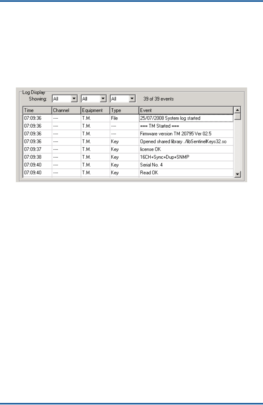
SGD-SB2025NT-TUM, Part 2
Jan 12 Page 97
TM LOGGING
(b). ‘
Channel
’. The channel number encompassing the event is displayed when appropriate. On
single channel versions this will only be “Chn 01”.
(c). ‘
Equipment
’. The equipment or hardware unit that experienced the event. Typical data is
“TM”, “Cen 01” and “Stn 02” etc.
(d). ‘
Type
’. The area of the equipment in which the event occurred. Typical data is “File”, “Key”
and “NI”, etc.
(e). ‘
Event
’. The details of the event itself. This varies widely according to both the event itself
and the log subject.
Figure 85. Example of a System Log.
A log entry that does not have information that relates to a data field will be displayed as ‘----‘ in
that column. In the above system log file display, every entry is an example of the latter situation
as these are all concerned with the TM itself, which has no channel association and so the
Channel data fields are shown as ‘----‘. Similarly the entries for TM start-up and firmware have no
‘Type’ data.
13.6.3 Filtering the Log Display
The ‘Channel’, ‘Equipment’ and ‘Type’ columns may be filtered to allow closer examination of
specific details and this feature operates in a very similar way to that available in spreadsheet
applications. Once a filter is applied, the list will be reduced and the number of events that match
that filter setting will be shown in the display header area.
The example overleaf has been constructed for handbook purposes as it is not possible to operate
all three pull down lists simultaneously even though all three columns may be filtered together.
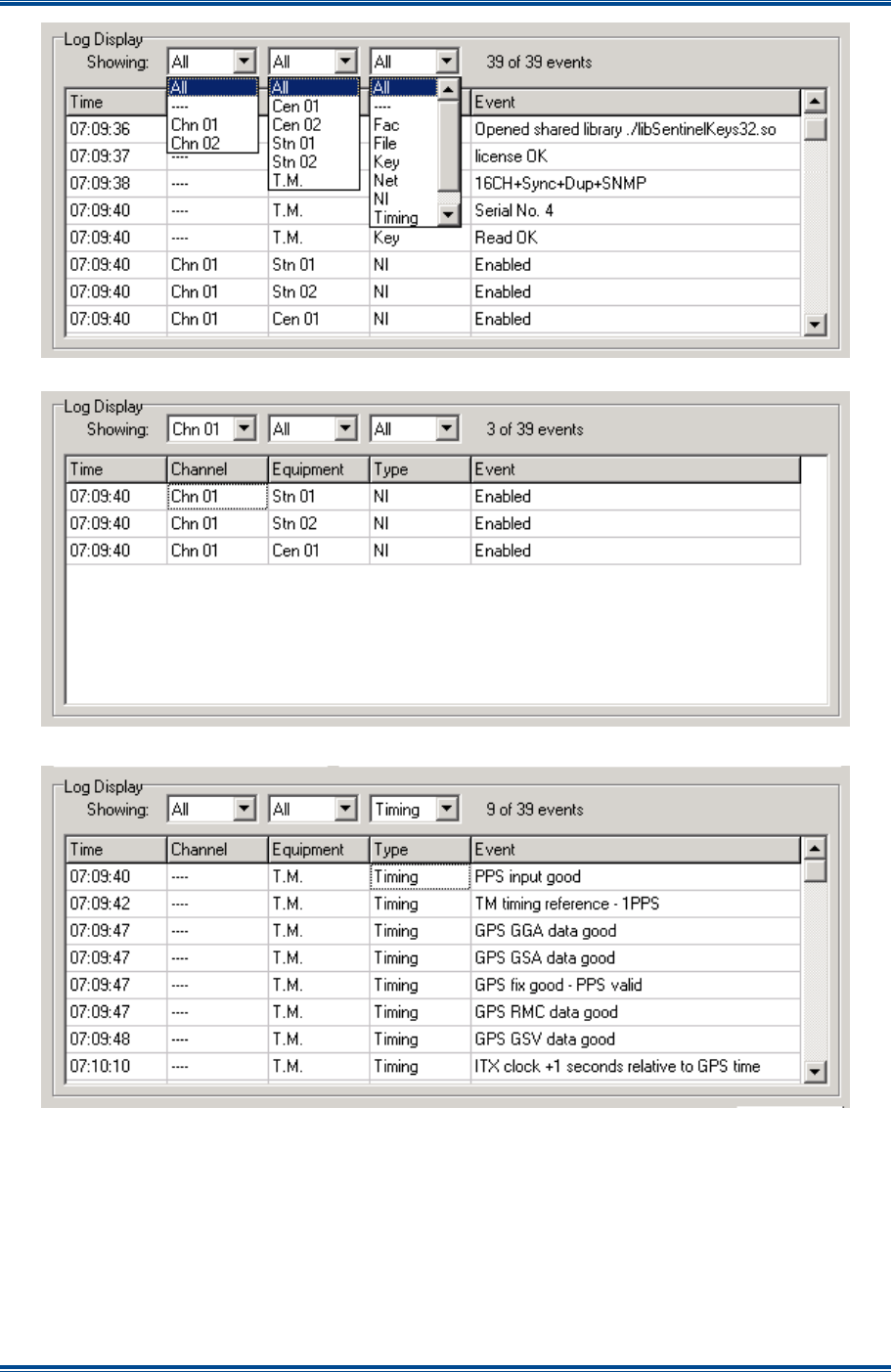
SGD-SB2025NT-TUM, Part 2
Jan 12 Page 98
TM LOGGING
Figure 86. Applying a Display Filter.
Figure 87. Filtering the Log Display on ‘Channel’.
Figure 88. Filtering the Log Display on ‘Type’.
More than one column may be filtered at the same time. To remove a filter select ‘All’ from the
drop-down list. A filter must be removed before selection of a different filter item can be made in
order to show the full list of selectable items.
The complete log file will be saved when the file save function is used even if one or more filters
are currently being applied.

SGD-SB2025NT-TUM, Part 2
Jan 12 Page 99
TM LOGGING
13.7 E
VENTS
A
CROSS
M
ULTIPLE
L
OGS
There will be events that cause a log entry to occur in more than one event log. An example of
such a situation is the loss of the PPS signal at a NI. This could be logged as an alarm (if so
configured) but would also be logged as a system event as the TM would remove the entry for that
NI from the timing table.
This highlights the fact that it might prove necessary to take information from more than one log file
to interpret the full details of an event, if a detailed investigation into the circumstances surrounding
an event is required.

SGD-SB2025NT-TUM, Part 2
Jan 12 Page 100
SNMP
14 SNMP
14.1 O
VERVIEW
O
F
SNMP
I
N
S
OLAR
This section details the setting up necessary to implement the SNMP facility and the functions that
are available through it. However, it does not go into any detail of SNMP operation, as it is
assumed the user will already have knowledge of and be familiar with SNMP. This feature is a
‘Facility Key’ enabled option which requires the Solar 2 ET and MIB file ‘DALMAN-SOLAR-MIB-
011.txt’ or higher.
SNMP is a defined standard for the data transfer between networks to be monitored and network
management systems. The use of SNMP will allow the user to monitor and control a Solar network
as well as providing indications of the operational status of the Solar network all in a manner that
suits the particular needs of the user.
To make use of the SNMP facility, the user is required to provide a NMS. There are many
commercially available NMS software packages to choose from or perhaps the user has an
existing NMS, therefore, it might be preferable to simply add the Solar SNMP to the existing NMS.
The SNMP implementation in the TM is SNMPv2 and a MIB is provided to define the data and data
structure of the information that is necessary for the NMS to operate into Solar. Certain objects
have Object Identifiers (OIDs) defined in the standard mib-2; these include the “sysDescription”,
“sysContact”, “sysName”, “sysLocation” strings and “sysUpTime”. Also defined in mib-2 are the
“Coldstart” and “Warmstart” traps sent when the TM starts up.
The SNMP facility does not replace the requirement for using the ET, since the basic configuration
of a Solar network must be undertaken using the ET before the SNMP facility itself can be realised.
Thereafter, although some of the parameters of the Solar network equipment can be accessed and
altered through SNMP, the majority can only be accessed using the ET.
14.2 C
ONFIGURING
SNMP
I
N
T
HE
TM
As long as the ‘Facility Key’ has the SNMP feature enabled, the ‘SNMP’ table of entries will be
enabled on the ‘Facility’ page of ‘TM Engineering’.
The SNMP setup information is presented under two pages: ‘Communities’ and ‘Destinations’. The
default text settings in ‘SNMP Communities’ and ‘System’ must all be changed to suit and the
appropriate IP addresses entered in ‘Destinations’.
14.2.1 SNMP Communities and System
All these entries are simple text strings but, as the purpose of those in the ‘Communities’ area is
similar to that of password access, the default settings for ‘Read Only’, ‘Read-Write’ and ‘Trap’
should be changed to protect the Solar network from unauthorised access. The ‘System’ values
are used to provide information about the monitored network. These can also be changed as
required, perhaps to make this network more readily identifiable as a Solar network if the NMS is
monitoring several networks.
To change any of the text strings, depress the ‘Eng’ button then select the item to be changed and
edit the existing string or enter a new text string as appropriate. To complete the change, the
‘Apply’ button must be selected which will automatically release the ‘Eng’ button.
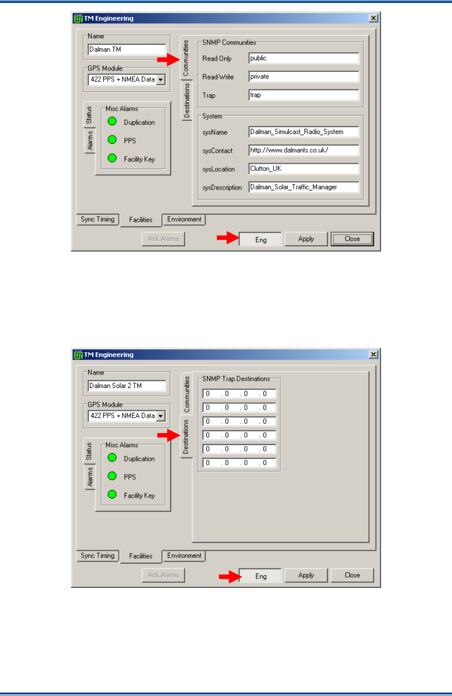
SGD-SB2025NT-TUM, Part 2
Jan 12 Page 101
SNMP
Figure 89. SNMP Text Label/Data Entry.
14.2.2 Trap Destinations
The IP addresses entered into any of these fields (to a maximum of six) will be the locations to
which any trap event notification is sent. To enter or change an IP address, depress the ‘Eng’
button and position the mouse pointer on the entry to be changed or added and click the mouse
button to activate the edit cursor (caret).
Figure 90. SNMP Trap Address Entry.
The keyboard “Tab” key will move the cursor from left to right and then down to the next address
line highlighting each item (octet value) in turn. Once the changes have been made, select the
‘Apply’ button, which will save the changes and automatically release the ‘Eng’ button.
The “Default Gateway” address entered in the main TM ‘Network’ setup will be used in conjunction
with the trap destination addresses.

SGD-SB2025NT-TUM, Part 2
Jan 12 Page 102
SNMP
14.3 D
ATA
O
RGANISATION
The data and meaning of the information that can be monitored by the SNMP NMS is detailed in a
MIB file. This file is provided by Simoco and contains all the necessary references, plain text
translations and value limitations that are applicable to every item of data that is accessible with
the NMS using SNMP.
14.3.1 Data Format
A summary of the data is set out in the following tables and the meaning of each column headings
is:
(a).
Data Item
. A short text description of the item in question.
(b).
Type
. ‘Single’ means that there is only one such item in the network; ‘Multiple’ means the
entity in question has to be uniquely addressed as many of them exist in the network. In
“Traps” the source of the event may be from multiple items.
(c).
Access
. Data may be read from the item or written to the item or both.
(d).
Data type
. The nature of the data stored for the item.
(e).
Notes
. Any supplementary information about the data item.
14.3.2 Network Interfaces (Centrals and Stations)
Table 6. SNMP Data Format for NI Info.
Data Item Type Access Data Type Notes
Maximum Number Single Read Integer 0 to 16 for Centrals : 1 to 32 for
Stations
IP Address Multiple Read IP Address
Enabled Multiple Read Integer 0 or 1
Name Multiple Read Text String
Environment Multiple Read Integer Bit representation of I/Ps and O/Ps
Alarms Multiple Read Integer Bit representation of alarms and
acknowledges
Alarm Acknowledge Multiple Read/Write Integer Acknowledges active alarms
14.3.3 Channels
Table 7. SNMP Data Format for Channel Info.
Data Item Type Access Data Type Notes
Maximum Number Single Read Integer 1 to 16
Name Multiple Read/Write Text String
Tx Key Hang Time Multiple Read/Write Integer 0 to 5 (seconds)
CTCSS Freq. Multiple Read/Write Integer 500 to 3000 (x 0.1 Hz)
RSSI Threshold Multiple Read/Write Integer 0 or 14
Voter Override Multiple Read/Write Integer 0 to 32 (Stn No : 0 = off)
Site Deselect Time Multiple Read/Write Integer 0 to 6 (5 mins : 0 = off)
TM triggered T/T Multiple Read/Write Integer 0 to 2
Channel Status Multiple Read Integer
Bit representation of voted site and
RSSI level

SGD-SB2025NT-TUM, Part 2
Jan 12 Page 103
SNMP
14.3.4 Traffic Manager
Table 8. SNMP Data Format for TM Info.
Data Item Type Access Data Type Notes
Uptime Single Read Integer Seconds since program start
Facility Key Status Single Read Integer 0 to 2
Key Serial Number Single Read Integer Unique serial number
Key Text Single Read Text String
Duplication Status Single Read Integer Bit representation of setting and
status
Alarms Single Read Integer Bit representation of alarms and
acknowledges
Alarm Acknowledge Single Read/Write Integer Acknowledges active alarms
14.3.5 Traps
Table 9. SNMP Data Format for Trap Info.
Data Item Type Data Type Notes
TM Alarms Single Integer Bit representation of active alarms
Station NI Alarms Multiple Integer Bit representation of active alarms
Central NI Alarms Multiple Integer Bit representation of active alarms

SGD-SB2025NT-TUM, Part 2
Jan 12 Page 104
FIRMWARE EXTENSIONS
15 FIRMWARE EXTENSIONS
15.1 F
IRMWARE
E
XTENSIONS
–
O
VERVIEW
The firmware installed in a NI is the same for all users. However, extension modules are
supported in the firmware, which will be created to perform specific and dedicated functions.
These extension modules will be activated according to the setting of the FW Config Byte, which is
displayed on the ‘Facilities’ page of ‘NI Engineering’ (see
Section 8.2.3 – Facilities
).
The ‘FW Config’ setting is displayed as a hexadecimal byte value and value 0x7FFF is the default
or base setting that does not implement any extension facility. This setting is only programmable
in the factory and, therefore, the user cannot elect to use a particular feature set. The NI will
perform only those duties that the equipment has been built to fulfil, although, when an extension is
enabled, individual items of that feature set may be enabled or not as desired; if none are enabled
the unit will operate as standard.
The configurations available from the NI are listed in order of the ‘FW Config’ byte value in
Table 10
. As more variants evolve they will be added to this document.
Table 10. Configuration Byte Usage.
Date Config Byte Function/Facility Section
Original 0x7FFF Standard build, no extension features available N/A

SGD-SB2025NT-TM, Part 2
Jan 12 Page 105
APPENDIX A
APPENDIX A
SOLAR CONFIGURABLE SETTINGS
The intention here is to list the user configurable settings of a Solar network in alphabetical order
and to indicate which ET has access to which. The precursor to any change is likely to need
selection of an engineering mode and the conclusion being that the change needs to be applied
(see the relevant section in the handbook for full details).
Many of the settings are accessible from either the TM ET or the NI ET and this is indicated by the
text ‘Both ET’ in the ‘ET’ column. As a Solar 2 unit may have either a TM or an NI or both fitted as
main modules and that the GPS and the Environment I/O sub-modules may be accessed through
the ET appropriate to the unit build, then these settings are shown as ‘Either’. A setting that is
available to only one of the ETs is indicated by the text ‘TM ET’ or ‘NI ET’ as appropriate. Any
further information is noted where applicable.
The ‘Type’ column indicates the nature of the setting by using the following notation:
• ‘Button’ – click in or out to enable/disable or set on/set off etc.
• ‘Check’ – check the box to enable, un-check the box to disable.
• ‘Click’ – single (momentary) action to instigate function.
• ‘Drag/drop’ – the selection is made using a ‘Drag and drop’ operation.
• ‘Enter’ – the user must enter a value (usually validated) or character string (not usually
validated).
• ‘Select’ – select the option from a pull-down list (fixed choice).
• ‘Slider’ – the setting is adjusted by dragging a slider to the required position/level.
Table A1. List of ET Settings.
Topic Description Options/Notes Type Location (ET page) ET
Alarms
Configuration and
acknowledgement of
alarm events
Enable/Disable alarm
events & acknowledge
alarms
Button Alarms (alarms
button, TM Tab) TM ET
Audio In Set audio I/P – fine
level Approx 6 dB range Slider NI Engineering (Main
audio tab) Both ET
Audio In Set audio I/P – coarse
level
0 to −18 dB, then −20
to −32 dB (6 dB steps)
Slider NI Engineering (Main
audio tab) Both ET
Audio In In route Normal/Inverted Button NI Engineering (Main
audio tab) Both ET
Audio In Enable 2.6 kHz LPF On/Off Check Setup (Misc tab) Both ET
Audio Out Set audio O/P – fine
level Approx 6 dB range Slider NI Engineering (Main
audio tab) Both ET
Audio Out Set audio O/P –
coarse level
0 dB to −21 dB (3 dB
steps) Slider NI Engineering (Main
audio tab) Both ET
Audio Out Out route Normal/Inverted Button NI Engineering (Main
audio tab) Both ET
Channel
Allocation
Relations: allocate
each NI to a channel Associate any to any Drag/drop
Relations (Relations
button, TM tab) TM ET
Channel
Facilities
Channel Name:
identify channel
Up to 20 characters
text Enter Channel Setup (Setup
button, channel tab) TM ET

SGD-SB2025NT-TM, Part 2
Jan 12 Page 106
APPENDIX A
Topic Description Options/Notes Type Location (ET page) ET
Channel
Facilities TX Key Hang 0 secs – 5 secs Select Channel Setup (Setup
button, channel tab) TM ET
Channel
Facilities TM Triggered T/T None/Perm/Central NI
fail Select Channel Setup (Setup
button, channel tab) TM ET
CTCSS CTCSS frequency 50 Hz to 300 Hz (to
0.1 Hz) Enter Channel Setup (Setup
button, channel tab) TM ET
CTCSS CTCSS out route Feature not in use Button NI Engineering
(CTCSS tab) Both ET
CTCSS CTCSS tone O/P –
fine level Approx 3 dB range Slider NI Engineering
(CTCSS tab) Both ET
CTCSS CTCSS tone O/P –
coarse level
0 dB to −21 dB (3 dB
steps) Slider NI Engineering
(CTCSS tab) Both ET
DSP Firmware
Read in FW file Load file into ET Button DSP button (Loader) NI ET
DSP Firmware
Upload FW to NI Start upload process Button DSP button (Loader) NI ET
Environment Set I/O text tables Max 20 characters Enter Setup (Labels tab) Either
Environment Configure the
environment I/Ps
Monitor/Auto with
invert options Select Setup (Misc tab) Either
Environment Configure the
environment O/Ps Manual/Auto Select Setup (Misc tab) Either
Environment Environment O/P
control O/Ps 1 to 8: On/Off Button NI Engineering
(Facilities tab) Either
GPS View GPS signals No action GPS (GPS button) Either
GPS Set PC Clock Select GPS > Options menu
(GPS button) Either
Isolated I/Ps Configure isolated
I/Ps Monitor/Auto Select Setup (Misc tab) Both ET
Isolated O/Ps Configure isolated
O/Ps (relays) Manual/Auto Select Setup (Misc tab) Both ET
NI Facilities Inhibit controls: I/P
and/or O/P On/Off Button NI Engineering
(Facilities tab) Both ET
NI Facilities Isolated (relay) O/P
controls Relay 1 to 3: On/Off Button NI Engineering
(Facilities tab) Both ET
NI Facilities Line fail T/T On/Off Button NI Engineering
(Station tab) Both ET
NI Name Set Station/Central NI
name Max 20 characters Enter Setup (Labels tab) Both ET
NI Network Set IP address Set to suit network
addressing scheme Enter NI Setup (Network
button) NI ET
NI Network Set Subnet mask Feature not in use Enter NI Setup (Network
button) NI ET
NI Network Set default gateway Feature not in use N/A NI Setup (Network
button) NI ET
NI Network Enable NI Enable/Disable Check NI Setup (Network
button) NI ET
Signalling In I/P signal type Tone/Voltage Select Setup (Signalling tab) Both ET
Signalling In Boundaries: min &
max
Tone: 2.6 – 3.5 kHz
V’age: 1 – 1023 Enter Setup (Signalling tab) Both ET
Signalling Out
O/P tone frequency 2.5 kHz – 3.6 kHz Select Setup (Signalling tab) Both ET
Signalling Out
O/P tone level −10 dB to −28 dB
(2 dB steps) Slider Setup (Signalling tab) Both ET
SNMP Setup ‘Communities’
parameters (3 entries)
Plain text (password) Enter SNMP (SNMP button,
TM tab) TM ET
SNMP Setup ‘System’
parameters (4 entries)
Plain text (info) Enter SNMP (SNMP button,
TM tab) TM ET

SGD-SB2025NT-TM, Part 2
Jan 12 Page 107
APPENDIX A
Topic Description Options/Notes Type Location (ET page) ET
SNMP Setup ‘Trap’
destinations (up to 6)
One IP address per
destination Enter SNMP (SNMP button,
TM tab) TM ET
Solar Event
Log Set System Time Action as required Click Logging (Logging
button, TM tab) TM ET
Solar Event
Log Read Log File Select Type & Date Select Logging (Logging
button, TM tab) TM ET
Solar Event
Log Transfer Log File Start transfer Click Logging (Logging
button, TM tab) TM ET
Solar Event
Log Filter Log File Action as required Select Logging (Logging
button, TM tab) TM ET
Solar Event
Log Save Log File Action if required Click Logging (Logging
button, TM tab) TM ET
Solar Timing GO Traffic O/P Time
(Station NI)
40 ms – 200 ms
(20 ms steps) Select Sync Timing (Sync
button, TM tab) TM ET
Solar Timing RTN Traffic O/P Time
(Central NI)
40 ms – 200 ms
(20 ms steps) Select Sync Timing (Sync
button, TM tab) TM ET
Solar Timing GO TM Buffer
(Central NI)
20 ms – 140 ms
(20 ms steps) Select Sync Timing (Sync
button, TM tab) TM ET
Solar Timing RTN TM Buffer
(Station NI)
20 ms – 140 ms
(20 ms steps) Select Sync Timing (Sync
button, TM tab) TM ET
Test Tone Test tone route External/Network/Off Button NI Engineering
(Facilities tab) Both ET
Test Tone Test tone frequency 300 Hz – 2500 Hz Enter NI Engineering
(Facilities tab) Both ET
Test Tone Test tone level 0 dB to −10 dB (1 dB
steps & −4.4 dB) Slider NI Engineering
(Facilities tab) Both ET
Timing Source
(NI)
Select 1PPS and
NMEA data source
RS422/TTL: with/
without NMEA data Select Setup (Misc tab) Either
Timing Source
(TM)
Select 1PPS and
NMEA data source
RS422/TTL: with/
without NMEA data Select Sync Timing (Setup
button, TM tab) Either
TM
Duplication Duplication mode Unduplicated
Dupl.(Pri), Dupl.(Sec) Select TM Setup (Network
button, TM tab) TM ET
TM
Duplication IP address Set to address of
“other” TM Enter TM Setup (Network
button, TM tab) TM ET
TM Network TM IP address Set to suit network
addressing scheme Enter TM Setup (Network
button, TM tab) TM ET
TM Network Set subnet mask Set to suit network
addressing scheme Enter TM Setup (Network
button, TM tab) TM ET
TM Network Default gateway Set to suit network
addressing scheme Enter TM Setup (Network
button, TM tab) TM ET
TM Setup –
Central NI IP Address Set to IP address of
required Central NI Enter Network button on
Central panel TM ET
TM Setup –
Central NI
Enable/Disable each
Central NI Enable/Disable Check Network button on
Central panel TM ET
TM Setup –
Station NI IP Address Set to IP address of
required Station NI Enter Numbered button on
Station panels TM ET
TM Setup –
Station NI
Enable/Disable each
Station NI Enable/Disable Check Numbered button on
Station panels TM ET
Voting (Chan)
Facilities
Minimum RSSI
Difference Select from 1 – 13 Select Channel Setup (Setup
button, channel tab) TM ET
Voting (Chan)
Facilities
Site Deselection
Timer
0 min – 30 min (5 min
steps) Select Channel Setup (Setup
button, channel tab) TM ET
Voting (Chan)
Facilities Voter Override Off/any enabled NI Select Channel Setup (Setup
button, channel tab) TM ET

SGD-SB2025NT-TM, Part 2
Jan 12 Page 108
APPENDIX A
Intentionally left blank.

Team Simoco Ltd, Field House, Uttoxeter Old Road, Derby DE1 1NH
Tel: +44 (0) 1332 375500
Fax: +44 (0) 1332 375501
www.teamsimoco.com
ComGroup Australia Pty Ltd, 1270 Ferntree Gully Road, Scoresby, Victoria, 3179, Australia
Tel: +61 (0)3 9730 3800
Fax: +61 (0)3 9730 3988
www.comgroup.net.au