Simoco Wireless Solutions SDP600AC SDP650AC and SDP660AC VHF Portable Radio Transceivers User Manual
Simoco Australasia Pty Ltd SDP650AC and SDP660AC VHF Portable Radio Transceivers
User Manual
SDP650 PORTABLE RADIO
USER MANUAL
TNM-U-E-0115, Issue – 1.1B
July 2013
Field House,
Uttoxeter Old Road
Derby
DE1 1NH
Tel: +44 (0) 1332 375500
FAX: +44 (0) 1332 375501
http://www.simocogroup.com
1270 Ferntree Gully Road,
Scoresby
Victoria, 3179
Australia
Tel: +61 (0)3 9730 3999
FAX: +61 (0)3 9730 3988
http://www.simocogroup.com
©Simoco 2013

SDP650 – USER MANUAL TNM-U-E-0115
Jul 13 (Iss. 1.1) Page 2 PREFACE
PREFACE
D
ECLARATION
This User Manual covers the Digital Mobile Radio (DMR) Operating Instructions for the SDP650
Portable Radio Transceiver.
Any performance figures quoted are subject to normal manufacturing and service tolerances. The
right is reserved to alter the equipment described in this manual in the light of future technical
development.
Changes or modifications not expressly approved by the party responsible for compliance could
void the user’s authority to operate the equipment.
C
OPYRIGHT
All information contained in this document is the property of Simoco. All rights are reserved. This
document may not, in whole or in part, be copied, photocopied, reproduced, translated, stored, or
reduced to any electronic medium or machine-readable form, without prior written permission from
Simoco.
C
OMPUTER
S
OFTWARE
C
OPYRIGHTS
The AMBE+2
TM
voice coding Technology embodied in this product is protected by intellectual
property rights including patent rights, copyrights and trade secrets of Digital Voice Systems, Inc.
This voice coding Technology is licensed solely for use within this Communications Equipment.
The user of this Technology is explicitly prohibited from attempting to extract, remove, decompile,
reverse engineer, or disassemble the Object Code, or in any other way convert the Object Code
into a human-readable form. U.S. Patent Nos. #6,912,495 B2, #6,199,037 B1, #5,870,405,
#5,826,222, #5,754,974, #5,701,390, #5,715,365, #5,649,050, #5,630,011, #5,581,656,
#5,517,511, #5,491,772, #5,247,579, #5,226,084 and #5,195,166.
D
ISCLAIMER
There are no warranties extended or granted by this document. Simoco accepts no responsibility
for damage arising from use of the information contained in the document or of the equipment and
software it describes. It is the responsibility of the user to ensure that use of such information,
equipment and software complies with the laws, rules and regulations of the applicable
jurisdictions.
E
QUIPMENT AND
M
ANUAL
U
PDATES
In the interests of improving the performance, reliability or servicing of the equipment, Simoco
reserves the right to update the equipment or this document or both without prior notice.

SDP650 – USER MANUAL TNM-U-E-0115
Jul 13 (Iss. 1.1) Page 3 PREFACE
E
RRORS AND
O
MISSIONS
The usefulness of this publication depends upon the accuracy and completeness of the information
contained within it. Whilst every endeavour has been made to eliminate any errors, some may still
exist. It is requested that any errors or omissions noted should be reported to either of the
following who are part of the Simoco group:
Field House
Uttoxeter Old Road, Derby.
DE1 1NH. UK
1270 Ferntree Gully Road, Scoresby
Victoria. 3179
Australia
Tel: +44 (0) 871 741 1050 Tel: +61 (0)3 9730 3999
E-mail: customer.service@simocogroup.com E-mail: inquiry.aus@simocogroup.com
D
OCUMENT
H
ISTORY
Issue Date Comments
1.0 January 2013 Initial Issue.
1.1 July 2013 Additional General Precaution added, plus changes to Support
page email addresses.
R
ELATED
D
OCUMENTS
1. TNM-M-E-0033. SDP600 Series DMR Portable Radio Transceivers – Service Manual,
Issue 1.0.
2. TNM-U-E-0117. SDP650 Portable Radio – Brief User Guide, Issue 1.1, dated July 2013.
3. TNM-U-E-0118. PAR-600CRG1 Single Rapid Charger – SDP650/660 Instruction Manual,
Issue 1.0, dated January 2013.
To order printed copies of this or any of the above publications, please contact Simoco. See the
Support page for contact information.
A comprehensive list of documentation is available for download on the Simoco website
http://www.simocogroup.com via the Partner Portal.

SDP650 – USER MANUAL TNM-U-E-0115
Jul 13 (Iss. 1.1) Page 4 CONTENTS
TABLE OF CONTENTS
Page
Title Page ......................................................................................................................................1
Preface .......................................................................................................................................... 2
Table of Contents (This List) ....................................................................................................... 4
List of Figures ..............................................................................................................................6
List of Tables ................................................................................................................................ 6
Personal Safety ............................................................................................................................7
Warnings ....................................................................................................................................... 7
Compliance with RF Energy Exposure Guidelines (United States and Canada) ......................9
General Notes ............................................................................................................................. 12
Support – Contact Information .................................................................................................. 13
Abbreviations .............................................................................................................................14
Glossary ...................................................................................................................................... 15
1
INTRODUCTION..................................................................................................................16
1.1
O
VERVIEW
........................................................................................................................16
1.2
C
ONFIGURATION
...............................................................................................................16
1.3
F
EATURES
........................................................................................................................16
2
GETTING STARTED ........................................................................................................... 17
2.1
P
REPARING THE
R
ADIO
F
OR
U
SE
....................................................................................... 17
2.1.1
Charging the Battery............................................................................................... 17
2.1.1.1
Procedure...................................................................................................... 17
2.1.2
Fitting the Battery ...................................................................................................18
2.1.3
Fitting the Antenna .................................................................................................18
2.1.4
Fitting the Belt Clip .................................................................................................19
2.1.5
Fitting Audio Accessory/Programming Cable..........................................................19
2.2
C
ONFIGURATION
...............................................................................................................19
3
FRONT PANEL CONTROLS............................................................................................... 20
4
FUNCTIONS AND FACILITIES ...........................................................................................23
D
ISPLAY
....................................................................................................................................23
4.1
S
WITCH
O
N
/S
WITCH
O
FF
...................................................................................................23
4.2
A
DJUSTING THE
V
OLUME
...................................................................................................23
4.3
S
ELECTING A
Z
ONE
........................................................................................................... 24
4.4
S
ELECTING A
C
HANNEL
..................................................................................................... 24
4.5
M
AKING A
C
ALL
(T
RANSMITTING
)....................................................................................... 24
4.6
R
ECEIVING
........................................................................................................................25
4.6.1
Received Individual Calls........................................................................................ 25
4.7
E
MERGENCY
A
LARM
......................................................................................................... 25
4.7.1
Receiving Emergency Calls.................................................................................... 25
4.7.2
Making an Emergency Call..................................................................................... 25
4.8
S
CAN
F
UNCTIONS
............................................................................................................. 26

SDP650 – USER MANUAL TNM-U-E-0115
Jul 13 (Iss. 1.1) Page 5 CONTENTS
4.8.1
Scan Screen........................................................................................................... 26
5
MENU SYSTEM...................................................................................................................28
5.1
M
ENU
N
AVIGATION
............................................................................................................ 28
6
MENU SCREENS ................................................................................................................30
6.1
C
HANNEL
M
ENU
................................................................................................................30
6.2
Z
ONE
M
ENU
...................................................................................................................... 30
6.3
S
ETUP
M
ENU
....................................................................................................................31
6.4
U
SER
O
PTIONS
M
ENU
....................................................................................................... 31
6.5
M
UTE
A
DJUST
M
ENU
......................................................................................................... 31
6.6
C
ONTACT
M
ENU
................................................................................................................32
6.7
R
ADIO
I
NFORMATION
......................................................................................................... 33
6.8
RSSI M
ENU
...................................................................................................................... 33
6.9
C
ALL
L
OG
........................................................................................................................33
6.10
S
CAN
M
ENU
...................................................................................................................... 34
6.11
C
ONTRAST
M
ENU
..............................................................................................................34
6.12
A
LERT
V
OLUME
M
ENU
....................................................................................................... 35
6.13
S
PEAKER
V
OLUME
M
ENU
..................................................................................................35
6.14
K
EY
B
EEPS
....................................................................................................................... 35
6.15
B
ACKLIGHT
....................................................................................................................... 36
6.16
B
RIGHTNESS
M
ENU
........................................................................................................... 36
7
SPECIAL FUNCTIONS........................................................................................................ 38
7.1
C
HANNEL
U
P
A
ND
D
OWN
..................................................................................................38
7.2
Z
ONE
U
P AND
D
OWN
......................................................................................................... 38
7.3
S
CAN
O
N
/O
FF
...................................................................................................................38
7.4
S
KIP
.................................................................................................................................38
7.5
T
ALK
A
ROUND
O
N
/O
FF
..................................................................................................... 38
7.6
L
OW
P
OWER
..................................................................................................................... 38
7.7
G
O
T
O
C
HANNEL
1, 2, 3
OR
4............................................................................................38
7.8
M
ENU
............................................................................................................................... 38
7.9
S
HORTCUTS
...................................................................................................................... 38
7.10
R
ESET
..............................................................................................................................38
7.11
S
PEAKER
M
UTE
................................................................................................................39
7.12
U
NDEFINED
....................................................................................................................... 39
7.13
M
AN
D
OWN
....................................................................................................................... 39
7.14
L
ONE
W
ORKER
................................................................................................................. 40
7.15
DMR A
LL
C
ALL
................................................................................................................40
7.16
D
IAL
S
TRINGS
...................................................................................................................40
8
ACCESSORIES ................................................................................................................... 41
APPENDICES
A ALERT TONES AND MESSAGES.

SDP650 – USER MANUAL TNM-U-E-0115
Jul 13 (Iss. 1.1) Page 6 CONTENTS
LIST OF FIGURES
Page
Figure 1. Fitting the Battery. ......................................................................................................... 18
Figure 2. Fitting the Antenna. ....................................................................................................... 18
Figure 3. Fitting the Belt Clip. .......................................................................................................19
Figure 4. Fitting Audio Accessory/Programming Cable................................................................. 19
Figure 5. SDP650 Controls........................................................................................................... 20
Figure 6. Default screen. ..............................................................................................................23
Figure 7. Typical display sequence after Switch On. .................................................................... 23
Figure 8. Menu Navigation (Example). .........................................................................................29
Figure 9. Channel Menu............................................................................................................... 30
Figure 10. Zone Menu. .................................................................................................................30
Figure 11. Setup Menu................................................................................................................. 31
Figure 12. User Options Menu. .................................................................................................... 31
Figure 13. Mute Adjust screen...................................................................................................... 32
Figure 14. Contact Menu screen. .................................................................................................32
Figure 15. Radio Information Menu. .............................................................................................33
Figure 16. Radio Information screens........................................................................................... 33
Figure 17. RSSI Menu.................................................................................................................. 33
Figure 18. Call Log Menu screen.................................................................................................. 34
Figure 19. Scan Menu. .................................................................................................................34
Figure 20. Contrast Menu screen. ................................................................................................ 34
Figure 21. Alert Volume Menu screen. .........................................................................................35
Figure 22 Speaker Volume Menu.................................................................................................35
Figure 23. Key Beeps Menu screen. ............................................................................................36
Figure 24. Backlight Menu screen. ............................................................................................... 36
Figure 25. Brightness Menu screen.............................................................................................. 36
LIST OF TABLES
Page
Table 1. Charge Indications.......................................................................................................... 18
Table 2. SDP650 – Controls......................................................................................................... 21
Table 3. LED Indications. ............................................................................................................. 21
Table 4. SDP650 and SDP660 DMR Portable Radio Accessories................................................41
Table A1. Alert Tones................................................................................................................... 43

SDP650 – USER MANUAL TNM-U-E-0115
Jul 13 (Iss. 1.1) Page 7 PERSONAL SAFETY
PERSONAL SAFETY
S
AFETY
P
RECAUTIONS
These Safety Precautions, Warnings and Cautions advise personnel of specific hazards which may
be encountered when using the equipment covered in this manual and that control measures are
required to prevent injury to personnel, and damage to equipment and/or the environment.
Before using this equipment, personnel are to acquaint themselves with all risk assessments
relevant to the work site and the task. They must then comply with the control measures detailed
in those risk assessments.
References covering safety regulations, health hazards and hazardous substances are detailed
under the WARNINGS section below. These are referred to in this user manual when they are
encountered.
G
ENERAL
P
RECAUTIONS
Do NOT operate your portable radio, without a hands-free kit, whilst driving a vehicle.
Do NOT operate your radio in an explosive atmosphere – unless the radio’s level of IECEx
approval is approved for use in that atmosphere.
Obey the ‘Turn Off Two-way Radios’ signs where these are posted, e.g. on a petrol station
forecourt.
Do NOT touch the antenna while the radio is transmitting.
Do NOT use or store the batteries above +60 °C.
Do NOT dispose of batteries in a fire.
Do NOT operate the radio if the antenna has become disconnected or damaged.
Only recharge batteries in an approved battery charger.
H
AZARDOUS
S
UBSTANCES
Before using any hazardous substance or material, the user must be conversant with the safety
precautions and first aid instructions:
• On the label of the container in which it was supplied.
• On the material Safety Data Sheet.
• In any local Safety Orders and Regulations.
W
ARNINGS
Lithium Batteries
WARNING
LITHIUM BATTERIES. THIS EQUIPMENT USES LITHIUM ION
BATTERIES. REFER TO THE CONTROL OF SUBSTANCES
HAZARDOUS TO HEALTH REGULATIONS (COSHH) 2002 AND/OR THE
APPROPRIATE SAFETY DATA SHEET.
SDP650 – USER MANUAL TNM-U-E-0115
Jul 13 (Iss. 1.1) Page 8 PERSONAL SAFETY
Radio Frequency Radiation
WARNING
RADIO FREQUENCY RADIATION. A RADIO FREQUENCY (RF)
RADIATION HAZARD EXISTS IN THIS EQUIPMENT. TO AVOID RF
INJURY, DO NOT TOUCH THE ANTENNA WHEN THE TRANSMITTER IS
IN USE. DO NOT OPERATE TRANSMITTER WITH THE ANTENNA
DISCONNECTED.
Dangerous Voltages
Dangerous voltages exist in this equipment, for the appropriate Safety precautions, refer to the
relevant Electrical Safety Regulations appropriate to the country of operation.
WARNING
DANGEROUS VOLTAGES. DANGEROUS VOLTAGES EXIST IN ALL THE
BATTERY CHARGERS USED WITH THIS RADIO. FOR THE
APPROPRIATE SAFETY PRECAUTIONS REFER TO THE RELEVANT
ELECTRICAL SAFETY REGULATIONS APPROPRIATE TO THE
COUNTRY OF OPERATION.
HINTS FOR USING THE RADIO
When transmitting, hold the radio a few centimetres from your mouth and speak across it, rather
than into it. The microphone is located near the bottom left hand corner of the portable radio.
Keep the length of your conversation to a minimum to conserve battery life.
When it is possible to move location, avoid making calls from known poor signal-strength areas
such as the radio systems fringe areas (limit of range) or from screened or shadowed areas, e.g.
an underground car park or underpass.

SDP650 – USER MANUAL TNM-U-E-0115
Jul 13 (Iss. 1.1) Page 9 RF ENERGY COMPLIANCE
COMPLIANCE WITH RF ENERGY EXPOSURE GUIDELINES
(UNITED STATES AND CANADA)
RF E
NERGY
E
XPOSURE
A
WARENESS AND
C
ONTROL
I
NFORMATION AND
O
PERATIONAL
I
NSTRUCTIONS FOR
FCC O
CCUPATIONAL
U
SE
R
EQUIREMENTS
Before using your Simoco portable two-way radio, read this important RF energy awareness and
control information and operational instructions to ensure compliance with the Federal
Communication Commission’s (FCCs) RF exposure guidelines.
NOTICE.
This radio is intended for use in Occupational/Controlled conditions in a portable
application where users have full knowledge of their exposure and can exercise control
over their exposure to meet the occupational limits in FCC/ICNIRP and International
Standards. This radio device is NOT authorised for general population consumer use.
This two-way radio uses electromagnetic energy in the Radio Frequency (RF) spectrum to provide
communications between two or more users over a distance. It uses RF energy or radio waves to
send and receive calls. RF energy is one form of electromagnetic energy. Other forms include,
but are not limited to, electric power, sunlight and x-rays. RF energy, however, should not be
confused with these other forms of electromagnetic energy, which, when used improperly, can
cause biological damage. Very high levels of x-rays, for example, can damage tissues and genetic
material.
Experts in science, engineering, medicine, health and industry work with organizations to develop
standards for safe exposure to RF energy. These standards provide recommended levels of RF
exposure for both workers and the general public. These recommended RF exposure levels
include substantial margins of protection. All Simoco two-way radios are designed, manufactured
and tested to ensure they meet government established RF exposure levels. In addition,
manufacturers also recommend specific operating instructions to users of two-way radios. These
instructions are important because they inform users about RF energy exposure and provide
simple procedures on how to control it. Please refer to the following websites for more information
on what RF energy exposure is and how to control your exposure to assure compliance with
established RF exposure limits.
http://transition.fcc.gov/oet/rfsafety/rf-faqs.html
http://www.osha.gov/SLTC/radiofrequencyradiation/
Federal Communications Commission Regulations
The FCC rules require manufacturers to comply with the FCC RF energy exposure limits for
portable two-way radios before they can be marketed in the United States (US). When two-way
radios are used as a consequence of employment, the FCC requires users to be fully aware of and
able to control their exposure to meet occupational requirements. Simoco two-way radios have an
exposure awareness label attached to the equipment directing users to specific awareness
information. Do not remove this exposure awareness label from the device. Additionally, your
Simoco user manual or separate safety booklet includes information and operating instructions
required to control your RF exposure and to satisfy compliance regulations.
Compliance with RF Exposure Standards
Simoco two-way radios are designed and tested to comply with a number of national and
international standards and guidelines (listed below) for human exposure to RF electromagnetic
energy. This radio complies with the IEEE (FCC) and International Commission on Non-Ionizing
Radiation Protection (ICNIRP) exposure limits for Occupational/Controlled RF exposure
environments at operating duty factors of up to 50% talk 50% listen and is authorised by the FCC

SDP650 – USER MANUAL TNM-U-E-0115
Jul 13 (Iss. 1.1) Page 10 RF ENERGY COMPLIANCE
for occupational use. In terms of measuring RF energy for compliance with these exposure
guidelines, your radio generates measurable RF energy only while it is transmitting (during talking),
not when it is receiving (listening) or in standby mode.
Your Simoco two-way radio complies with the following RF energy exposure standards and
guidelines:
• United States Federal Communications Commission, Code of Federal Regulations; 47CFR
part 2 sub-part J.
• American National Standards Institute (ANSI)/Institute of Electrical and Electronic Engineers
(IEEE) C95.1-1992.
• Australian Communications Authority Radio Communications Standard et seq.
• Institute of Electrical and Electronic Engineers (IEEE) C95.1-1999 Edition.
• Industry Canada RSS-102.
RF Exposure Compliance and Control Guidelines and Operating Instructions
To control exposure to yourself and others and ensure compliance with the
Occupational/Controlled environment exposure limits always adhere to the following procedures.
Guidelines:
• User awareness instructions should accompany the device when transferred to other users.
• This radio meets the FCC RF exposure guidelines when used with the Simoco accessories
supplied or designated for the product. The designated Simoco belt clip type is PAR-
600CLIP and the extension speaker microphone types are PAR-9180LMS2-2, PAR-
9180LMW1 and PAR-600LMS4. Use of other accessories may not ensure compliance with
the FCC’s RF exposure guidelines and may violate FCC regulations.
• Do not use this device if the operational requirements described herein are not met.
Instructions:
• Transmit no more than the rated duty factor of 50% of the time. To transmit (talk), push the
Push-To-Talk (PTT) button. To receive calls (listen), release the PTT button. Transmitting
50% of the time, or less, is important because the radio generates measurable RF energy
exposure only when transmitting (in terms of measuring for standards compliance).
• Do not operate the radio without an approved antenna attached, as this may cause the FCC
RF exposure limits to be exceeded. With this product, only use an antenna supplied or
approved by Simoco.
• Always keep the radio at least 5 cm (2.0 inches) from the face when transmitting and at least
10 mm (0.4 inches) from the body. This radio has been tested for RF exposure compliance
at the distances listed in Table 1.
Table 1. RF Exposure Compliance Distances
Frequency Band Bodyworn Handheld in front of Face
AC: 136 MHz – 174 MHz 10 mm (0.4 inches) 25 mm (1.0 inches)
TU: 400 MHz – 480 MHz 10 mm (0.4 inches) 25 mm (1.0 inches)
UW: 440 MHz – 520 MHz 10 mm (0.4 inches) 25 mm (1.0 inches)

SDP650 – USER MANUAL TNM-U-E-0115
Jul 13 (Iss. 1.1) Page 11 RF ENERGY COMPLIANCE
Approved Accessories
• This radio meets the FCC RF exposure guidelines when used with the Simoco accessories
supplied or designated for the product. Use of other accessories may not ensure compliance
with the FCCs RF exposure guidelines and may violate FCC regulations.
• To obtain a list of Simoco approved accessories please see the Simoco Group Departmental
contact details on the Support page and either contact the relevant Technical Support
Helpline or Customer Services, visit the following website, which lists approved accessories:
http://www.simocogroup.com
For additional information on exposure or other information, please see the Simoco Group
Departmental contact details on the Support page and contact the relevant Technical Support
Helpline or Customer Services.

SDP650 – USER MANUAL TNM-U-E-0115
Jul 13 (Iss. 1.1) Page 12 GENERAL NOTES
GENERAL NOTES
M
ANUAL
C
OMPILATION
This manual provides detailed information on the use of the SDP650 DMR Portable Radio
Transceiver including Getting Started, Front Panel Controls, Basic Functions and Facilities, Menu
System, Menu Screens, Special Functions and Accessories.
Details of both the “default” and “optional” system configurations have been included in this User
Manual, therefore, some material may not be relevant to every system. Configuration is dependent
upon the specification by the customer when the equipment was ordered and installed.
P
AGINATION
This manual is divided into a number of sections, each section deals with one aspect of the
system.
Following initial issue, any page that has been amended or updated will also bear an updated
reference.

SDP650 – USER MANUAL TNM-U-E-0115
Jul 13 (Iss. 1.1) Page 13 SUPPORT
SIMOCO SUPPORT
C
ONTACT
I
NFORMATION
At Simoco we welcome your comments, feedback and suggestions. Departmental contacts have
been provided for your quick reference below.
UK Customer Services
Email: customer.service@simocogroup.com
Tel: UK: 08717 411 050
International: +44 (0) 1332 375 671
Fax: UK: 08717 411 049
International: +44 (0) 1332 376 672
Sales
E-mail sales@simocogroup.com
Marketing
E-mail marketing@simocogroup.com
Technical Support
E-mail: techsupport@simocogroup.com
Technical Support Helpline
Tel: UK: 08717 411 040
International: +44 (0) 1332 375 671
Australian Customer Services
Email: inquiry.aus@simocogroup.com
Tel: Within Australia: 1300 363 607
International: +61 3 9730 3999
US Customer Services
Email: customerservice@simocoamericas.com
Tel: +1 (0) 877 848 3876
Technical Support
E-mail: techsupport@simocoamericas.com

SDP650 – USER MANUAL TNM-U-E-0115
Jul 13 (Iss. 1.1) Page 14 ABBREVIATIONS
ABBREVIATIONS
The following abbreviations are used through out this document. Whenever practicable, wherever
the abbreviation is first used the full meaning is given with the abbreviation in parenthesis, after
that only the abbreviation will be used.
LIST OF ABBREVIATIONS
Abbreviation Meaning
AC Alternating Current
ANSI American National Standards Institute
CC Colour Code
COSHH Control Of Substances Hazardous to Health
CTCSS Continuous Tone Controlled Squelch System
DCS Digital Coded Squelch
DMR Digital Mobile Radio
DSP Digital Signals Processor
FCC Federal Communications Commission
FDMA Frequency Division Multiple Access
FPP Field Personality Programmer
GPS Global Positioning System
ICNIRP International Commission on Non-Ionizing Radiation Protection
ID Identification
IECEx International Electrotechnical Commission system for the certification to
standards for electrical equipment for Explosives atmospheres.
IEEE Institute of Electrical and Electronics Engineers
LCD Liquid Crystal Display
LED Light Emitting Diode
PABX Private Automatic Branch Exchange
PSTN Public Switched Telephone Network
PTT Push (Press) To Talk
RF Radio Frequency
RSSI Received Signal Strength Indicator
Rx Receiver
SDM Simoco Digital Mobile
SDP Simoco Digital Portable
SUID Subscriber Unit Identification
TGID Talk Group Identification
Tx Transmitter
UID Unit Identification
US United States

SDP650 – USER MANUAL TNM-U-E-0115
Jul 13 (Iss. 1.1) Page 15 ABBREVIATIONS
GLOSSARY OF TERMS
The table below contains a list of the common terms used through out this document and their
meanings.
Term Meaning
‘……’ Reference to a setting or feature (exactly as it is displayed) that may be
selected or enabled either directly or through a software application, e.g.
‘Menu’, ‘Control’, ‘Switch’.
Channel A logical combination of RF Frequency, Default Talk Group Indentity (TGID),
other channel associated parameters (CTCSS, scan etc)
CTCSS A sub-audio tone used for validating a received signal (also known as a PL
tone).
FPP Field Personality Programmer or Field Programmer. A Software Application
used for configuring the radio options and parameters.
Monitor Mode of Radio Receive. Any DMR signal regardless of Colour Code or TGID
will be heard.
Normal Mute Mode of Radio Receive. Only signals with matching Colour Code will be
heard.
Push To Talk The action or signal that causes the equipment to be placed into transmit
mode or to be keyed.
Radio Unit ID Unique identifier allocated to each radio (range: 0 – 16,000,000).
Scanning A process of selecting the first-found, permitted signal from one of several
possible radio channels carrying different signals, by sequentially scanning the
channels.
Selective Mode of Radio Receive. Only signals with matching Colour Code and TGID or
Unit ID will be heard.
Vote/voting A process to select a permitted radio signal of adequate signal quality from
one of several possible radio channels carrying the same signal, by
sequentially scanning the channels before and at the start of signal reception.
Zone A collection of channels (usually organised by functional group of users).

SDP650 – USER MANUAL TNM-U-E-0115
Jul 13 (Iss. 1.1) Page 16 INTRODUCTION
1 INTRODUCTION
1.1 O
VERVIEW
The SDP600 Series Radios are versatile Digital Signal Processor (DSP) controlled, two-way
portable radios. The SDP600 Series Radio is available in a number of frequency bands for specific
applications.
The radios are software programmable and can be customised to the operational requirements of
a customer’s particular fleet. Simoco representatives can help in programming the radio facilities
to meet a customer’s present and future requirements.
A comprehensive range of accessories is available to compliment the SDP600 Series Radios
including: chargers, antennas, remote speaker microphones, covert/surveillance kits, holsters and
carry cases. Refer to Simoco for comprehensive descriptions and pricing.
The SDP650 model offers seven function keys but no keypad.
This User Guide describes the facilities that are currently available and can be programmed into
the SDP650 Portables Radio.
1.2 C
ONFIGURATION
Before the SDP650 radio can be used it must be configured using the Field Personality
Programmer (FPP). The configuration process loads the customised channels, signalling and user
options so that the radio will operate with the user’s system.
1.3 F
EATURES
The SDP650 portable radio has the following features:
• Integrated Man Down - motion and positional sensor for full employee safety.
• IP67 performance for best in class resistance to water and dust.
• Ear-piece speaker for full-duplex calling mode.
• Bluetooth, enhances the radio with wireless accessories and applications.
• Integral Global Positioning System (GPS) Antenna for dedicated satellite performance placed
optimally within the radio.
• High output main speaker for loud & clear digital audio.
• 7-colour Light Emitting Diode (LED) with all-round viewing for clear indication of radio status.
• Easy access to emergency button for no-doubt notification.
• Ergonomic push-to-talk.
• Selector knob enhances usability, for control of volume and brings smart-phone speed-
scrolling to the radio.
• IP67 rated side-connector.
• Battery life 40% greater than equivalent analogue and Frequency Division Multiple Access
(FDMA) technologies.
• Simple display for easy four character channel identification.
• Two side programmable keys and two front programmable keys.
• Easy access up-and-down channel change.
SDP650 – USER MANUAL TNM-U-E-0115
Jul 13 (Iss. 1.1) Page 17 GETTING STARTED
2 GETTING STARTED
This User Manual covers the basic operation of the Simoco SDP650 Digital Portable radios.
The radios are software programmable and can be customised to the operational requirements of
a customer’s specific needs. Simoco representatives can help in programming the radio facilities
to meet a customer’s present and future requirements.
Users should check with their Simoco dealer or system administrator about the features
programmed into the radio and specifically about:
• Whether any preset conventional channels are programmed into the radio?
• Which buttons have been programmed to access other features?
• The optional accessories that may be required?
2.1 P
REPARING THE
R
ADIO
F
OR
U
SE
2.1.1 Charging the Battery
WARNING
LITHIUM BATTERIES. THIS EQUIPMENT USES LITHIUM ION
BATTERIES. REFER TO THE PERSONAL SAFETY PAGES.
The SRP650 radio is powered by either a 2200 mAh or a 3000 mAh Lithium Ion battery. To avoid
damage and comply with warranty terms, the battery should be charged with a Simoco Standard
Battery charger.
For best performance, new batteries should be charged for 5 hours before initial use.
2.1.1.1
Procedure
This charging procedure assumes that the PAR-600CRG1 Single Rapid Charger is used. For full
details on this charger, please refer to TNM-U-E-0118, PAR-600CRG1 Single Rapid Charger –
SDP650/660 Instructional Manual [3].
1 Connect the AC power adapter to an AC mains supply and to the socket on the back of the
charger.
2 Switch on the mains power. The Red LED on the charger will flash briefly. The charger is
now in standby mode.
3 Switch the radio off.
4 Place the battery pack, or the radio with the battery attached, into the charging slot on the
charger.
5 Check that the Red LED on the charger is illuminated.
6 The fast charging process will be initiated. When the battery pack is fully charged, the Green
LED on the charger will be illuminated (see Table 2 overleaf).
SDP650 – USER MANUAL TNM-U-E-0115
Jul 13 (Iss. 1.1) Page 18 GETTING STARTED
Table 2. Charge Indications.
LED States
Charge State Red LED Green LED
Battery absent Off Off
Fast Charge On Off
Charge Complete Off On
Charge suspended (High or Low Temp
1 Hz Flashing Off
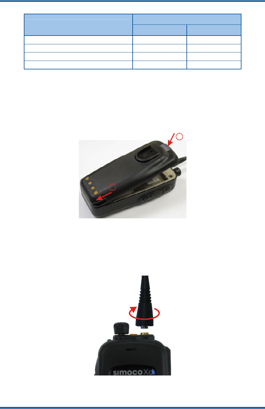
2.1.2 Fitting the Battery
Insert the battery into the bottom of the radio. (See arrow 1 in Figure 1 below).
Press down slightly on the battery release clip located at the top of the battery until a click is heard.
(See arrow 2).
Figure 1. Fitting the Battery.
To remove the battery, turn the radio off. Slide the battery release clip downwards to release the
battery.
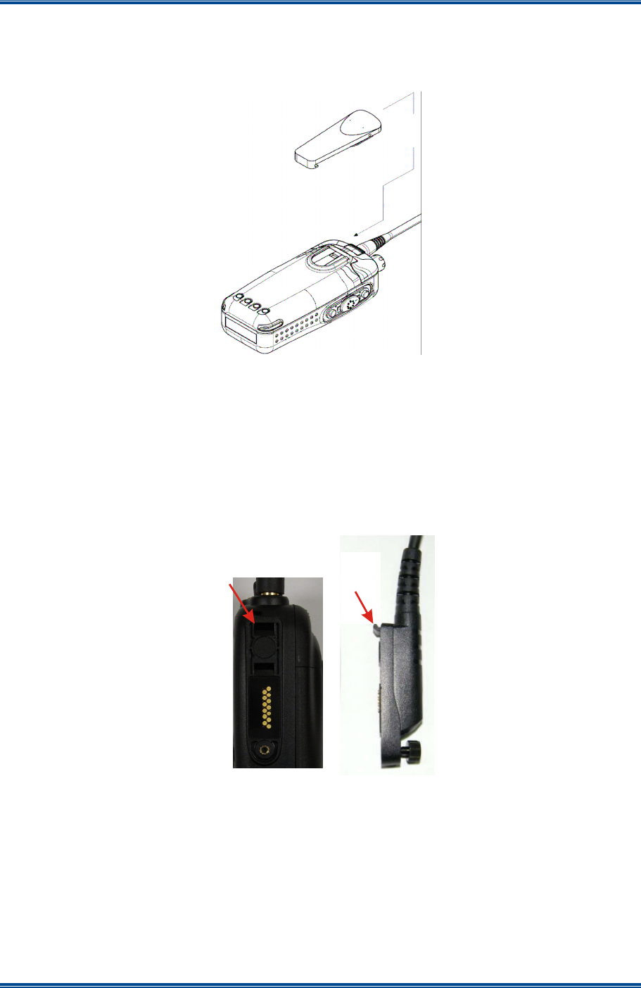
2.1.3 Fitting the Antenna
With the radio turned off, locate the antenna in its threaded socket and turn clockwise to tighten.
Figure 2. Fitting the Antenna.
To remove the antenna, ensure the radio is turned off and turn the antenna counterclockwise.
1
2
SDP650 – USER MANUAL TNM-U-E-0115
Jul 13 (Iss. 1.1) Page 19 GETTING STARTED
2.1.4 Fitting the Belt Clip
Align the belt clip with the grooves of the belt clip housing on the back of the battery. Push the belt
clip downwards until a click is heard.
Figure 3. Fitting the Belt Clip.
2.1.5 Fitting Audio Accessory/Programming Cable
1 On the side of the radio, release the retaining screw and remove the accessory socket cover.
2 On the audio accessory/programming cable, locate the tab lug of the connector into either
the top or bottom tab hole on the side of the radio as required (see Figure 4 below).
3 Tighten the screw to secure the audio accessory/programming cable to the radio.
Figure 4. Fitting Audio Accessory/Programming Cable.
2.2 C
ONFIGURATION
Before the SDP650 radio can be used it must be configured using the FPP. The configuration
process loads the customised channels, signalling and user options so that the radio will operate
with the user’s system.
Tab
Lug
Top
Tab
Hole
SDP650 – USER MANUAL TNM-U-E-0115
Jul 13 (Iss. 1.1) Page 20 FRONT PANEL CONTROLS
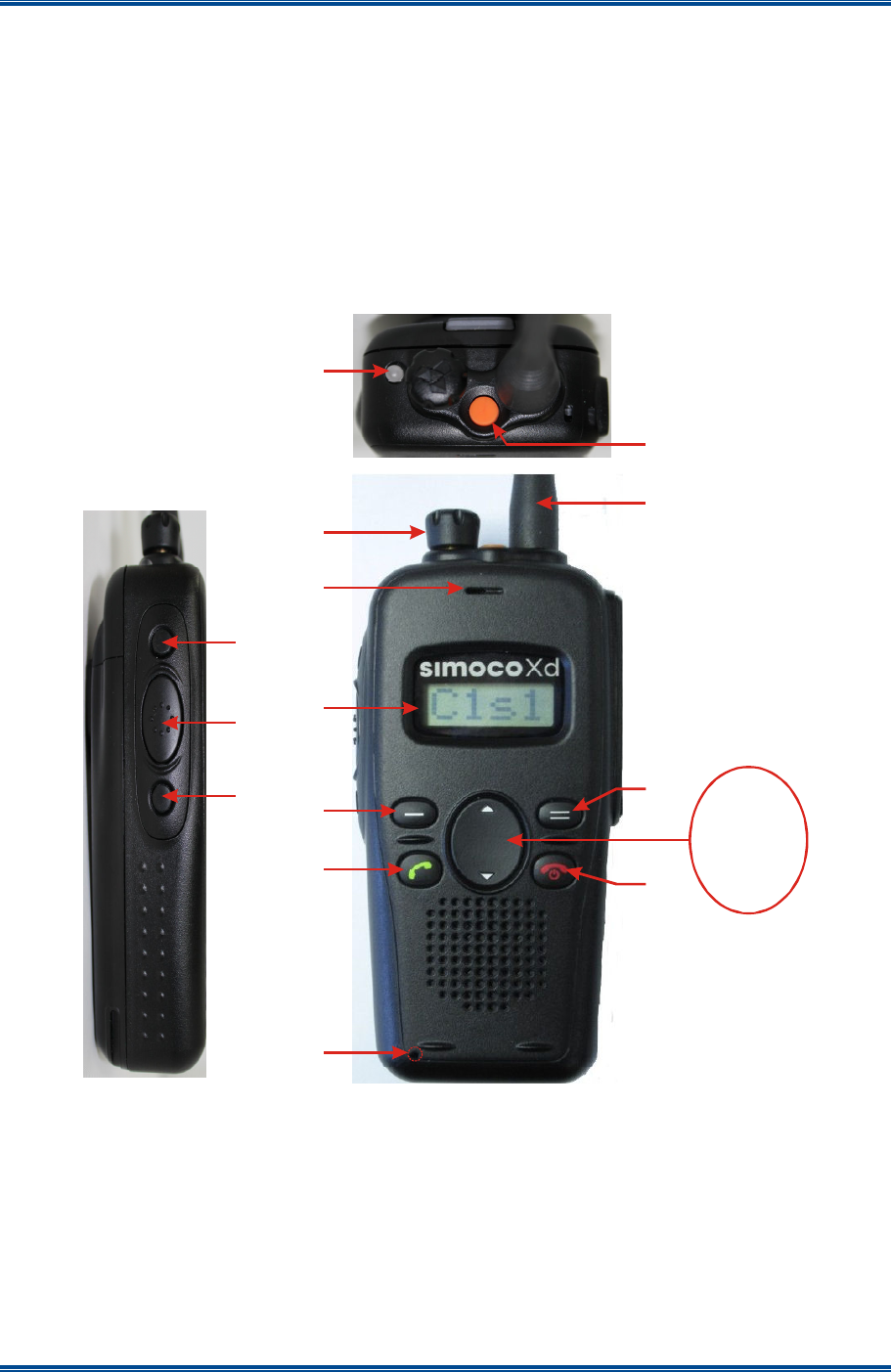
3 FRONT PANEL CONTROLS
The SDP650 portable Radios have the following features:
• Multiple programmable dedicated Function Buttons.
• Function buttons also have a second function provided by a longer button press.
• Multi-coloured LED for a clear indication of radio status.
• Simple display for easy four character channel identification.
The Controls of the SDP650 Portable radio are shown below in Figures 5.
Figure 5. SDP650 Controls.
The functions of each of the controls are detailed overleaf in Table 3.
Nav
Up
Nav
Down
1
2
3
4
5
6
7
8
9
10
11
12
13
14
15

SDP650 – USER MANUAL TNM-U-E-0115
Jul 13 (Iss. 1.1) Page 21 FRONT PANEL CONTROLS
Table 3. SDP650 – Controls.
No. Control Label
Function
1 Tx/Rx/Power
LED
Multi coloured LED. See Table 4 below for full details of colour indications.
2 Volume
Multifunction knob. Provides volume control (rotate clockwise to increase the
volume; counterclockwise to decrease the volume). Also provides channel
and zone selection, in conjunction with side-buttons F6 and F13.
3 Earpiece
4 Antenna
5 Function Key
F5
Prog. function key. Default – Emergency/Alarm.
6 Function Key
F6
Prog. function key. Allows multifunction knob to select zone if held down.
7 PTT Push To Talk. Hold the radio 10 cm from the mouth. Press and hold the PTT
switch and speak. Release the PTT switch to listen.
8 Function Key
F13
Prog. function key. Allows multifunction knob to select channel if held down.
9 Display
10 Function Key
F1
Menu Prog. function key. Default – Menu Select.
11 Function Key
F11 Prog. function key. Default – Start Call.
12 Function Key
F12 Prog. function key. Default – End Call, Cancel, power On/Off.
13 Function Key
F4
Prog. function key. Default – Back.
14 Nav-Up F7 ▲ Prog. function key. Default – Up key for scrolling.
Nav-Down F8 ▼ Prog. function key. Default – Down key for scrolling.
15 Microphone
The details of the multi-coloured LED indications are contained below in Table 4.
Table 4. LED Indications.
LED Colour
Meaning
LED Off. Radio is in idle state (no call activity).
Green Receiving a valid incoming signal.
Green Flashing Radio in talk-back hang time. (FPP defined parameter for digital channel).
Red Radio is transmitting.
Red Flashing Emergency Mode active. This is a FPP defined parameter
Orange Flashing Low Battery.
Blue Flash 1 * Bluetooth enabled, not paired. (Flash Rate: Every 3 secs, 10% duty cycle).
Blue Flash 2 * Bluetooth enabled, paired. (Flash rate: Every 1 sec, 10% duty cycle).
Blue Flash 3 * Bluetooth enabled, active. (Flash Rate: Every 200 ms, 50% duty cycle).
* Bluetooth facility – for future development.

SDP650 – USER MANUAL TNM-U-E-0115
Jul 13 (Iss. 1.1) Page 22 FRONT PANEL CONTROLS
SDP650 – USER MANUAL TNM-U-E-0115
Jul 13 (Iss. 1.1) Page 23 FUNCTIONS
4 FUNCTIONS AND FACILITIES
D
ISPLAY
The display shows text information relevant to the selected Menu Screen.
Figure 6. Default screen.
The Name field (e.g. C1s1) shows the selected entry from the current screen (e.g. from the
Channel List).
The F1 button is used to access the available Menu options. Where menu selection is not
required, this button can be reprogrammed to perform other functions in this screen.
The Nav Up (▲) and Nav Down (▼) buttons scroll up and down through the available selections
within a Menu Screen.
The F1, F2, F3 and F4 buttons are programmable function buttons, in this screen.
4.1 S
WITCH
O
N
/S
WITCH
O
FF
Press and hold down the On/Off button for approximately 2 seconds to switch the radio ON.
The display will illuminate and briefly show an “Opening Message” (arranged by your dealer) and
the Selcall Identity of the radio (if used).
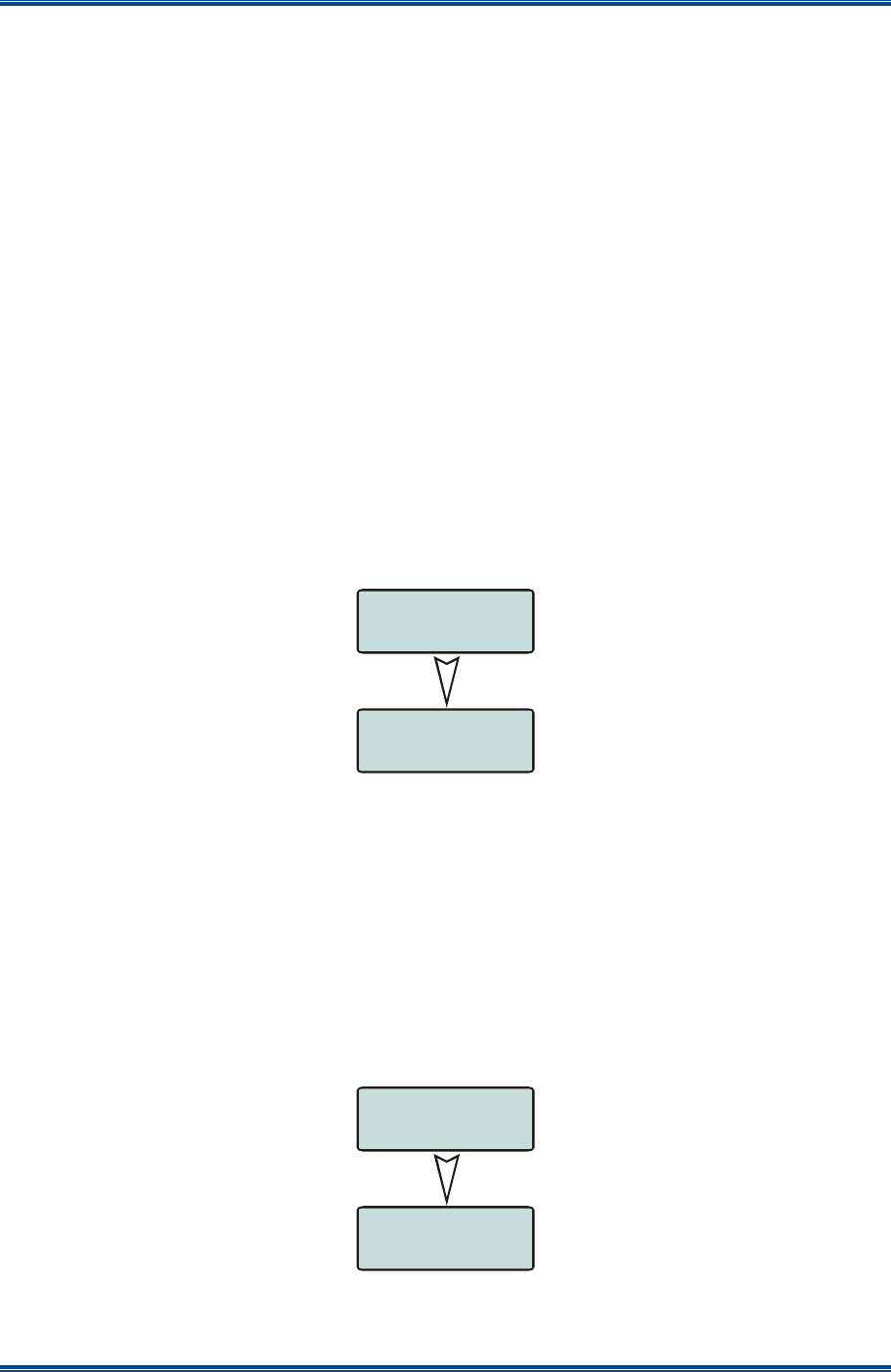
After a brief time the display will show the selected channel (see Figure 7 below), at which time the
radio is ready for use.
Figure 7. Typical display sequence after Switch On.
Pressing and holding the On/Off button for approximately 2 seconds will switch the radio Off.
If the radio Inactivity Timer is enabled, the radio will automatically turn off after several hours of
inactivity (i.e. no buttons pressed). The radio will emit warning beeps for 10 seconds prior to
switching off. Pressing any button will reset this timer.
The radio can also be set up to switch on automatically with the Vehicle Ignition whenever the
vehicle is started.
4.2 A
DJUSTING THE
V
OLUME
After turning the radio on, to adjust the volume, rotate the volume control knob clockwise to
increase it or counter-clockwise to decrease it.
C
1
s
1
C
1
s
1

SDP650 – USER MANUAL TNM-U-E-0115
Jul 13 (Iss. 1.1) Page 24 FUNCTIONS
4.3 S
ELECTING A
Z
ONE
Zones are groups of channels that are intended to be used in a particular geographical or
functional zone (e.g. North, South, Security, Fire Control). The radio supports up to 40 zones,
each with a maximum of 250 channels. A radio must have at least one zone defined to be
functional and a channel may be used in more than one zone.
A Zone can be selected as follows:
1 Through menu selection:
1.1 Go to the Zone menu, use the ▲ and ▼ keys to choose the required zone and press
the F1 key to select it.
2 By using the function keys:
2.1 From the main default screen, a zone can quickly be selected by pressing the ‘Zone
Up’ or ‘Zone Down’ function keys when these have been programmed.
4.4 S
ELECTING A
C
HANNEL
The radio can have up to 2000 channels in its channel database.
A channel can be selected as follows:
1 Through menu selection:
1.1 Go to the Channel menu, use the ▲ and ▼ keys to choose the required channel and
press theF1 key to select it.
2 By using the function keys:
2.1 From the main default screen, a channel can quickly be selected by pressing the
‘Channel Up’ or ‘Channel Down’ function keys when these have been programmed.
4.5 M
AKING A
C
ALL
(T
RANSMITTING
)
Select the Zone/Channel required on which to make the call.
To avoid interfering with other users of the channel, listen first to ensure no transmissions are
occurring.
To transmit, to the selected channel’s default radio talk group, hold the radio or microphone about
10 cm in front of the mouth and press the PTT switch. Wait until the radio indicates that the Tx is
transmitting and then speak clearly in a normal conversational manner.
In most systems it is important to wait a short time (0.5 secs) between pressing the PTT button and
commencing to speak. This allows the transmission path to be properly established (or not) and
avoids lost or distorted speech.
On some channels, the radio may provide alert tones to indicate the success or failure of the
establishment of the transmission path. Only speak after the tone indicating the transmission's
successful establishment. The radio’s LED will also turn Red to show that the transmitter is active
Use the correct operating procedure and keep transmissions as short as possible.
Release the PTT switch as soon as you have completed your message in order to hear any
replies. The radio cannot listen and talk to groups simultaneously.

SDP650 – USER MANUAL TNM-U-E-0115
Jul 13 (Iss. 1.1) Page 25 FUNCTIONS
If you wish to talk to other groups or individuals these can be selected on the contact menu or
dialled before pressing the PTT.
Notes:
(i).
A channel may be programmed as Receive-only or Transmit Inhibit, which can
disallow PTT. A continuous tone will be heard if PTT is attempted.
(ii).
A Transmit Limit Timer may be setup that limits a single continuous transmission.
The last 10 seconds before the timer expires may be accompanied by warning tones.
A call can be made as follows:
1 Go to the ‘Contact’ or ‘Call Log’ menus.
2 Use the ▲ and ▼ keys to select the contact you wish to call.
3 Press the PTT key to transmit the call.
4.6 R
ECEIVING
The radio will listen on the displayed Channel. Changing channels can be achieved by either:
• Pressing the ▲ ▼ buttons; or
• Pressing a “Go-to-Channel” Function Button, refer to Section 7.7.
When receiving a call, press the PTT key within the preset time period to call back.
4.6.1 Received Individual Calls
Unanswered received Individual calls addressed to the radio are stored in radio memory.
The caller UID may be viewed, answered and deleted by the user as desired.
A newly received individual call addressed to the radio sounds an alert tone periodically until the
user presses any key.
If the caller UID of a newly received unanswered call is already in the Call Log list, the old Call Log
record of that UID will be replaced by the new record and added to the top of the list.
To view/answer/delete received call records, select the Call Log menu option.
4.7 E
MERGENCY
A
LARM
4.7.1 Receiving Emergency Calls
When an emergency call is being received, a message will be displayed on the default screen
‘EMG’ indicating the radio unit sending the emergency call.
4.7.2 Making an Emergency Call
When the emergency key is pressed and held for a time determined by the FPP, the radio will
change to emergency mode. Under emergency mode, the radio can operate in three FPP
configurable modes:
• Frozen. The screen will freeze in the state it was in before the emergency mode became
active. The Emergency mode message will not be displayed, thus, showing no sign to the
observer that the emergency mode has been triggered.

SDP650 – USER MANUAL TNM-U-E-0115
Jul 13 (Iss. 1.1) Page 26 FUNCTIONS
• Blank. The screen will blank giving no indication to others that the radio is in emergency
mode.
When emergency mode is triggered, the radio can be configured by the FPP to transmit and
receive on a cyclic basis with FPP programmed time periods.
During Tx, the radio will generate an emergency broadcast call on either the currently selected
channel or an FPP nominated channel.
Others may listen to the automatic transmissions to hear conversations near the radio.
The power button is not operable in emergency alarm mode.
The radio can be programmed to exit emergency alarm mode when the number of programmed
cycles is completed or to remain in emergency alarm mode. To terminate the emergency alarm
mode, the battery must be disconnected and re-connected.
4.8 S
CAN
F
UNCTIONS
The Scan Function allows the sequential searching of up to 16 channels, if the selected zone
channel is programmed as a Scan channel, for a valid signal (Carrier + CTCSS/DCS tone for
Analogue FM or Colour Code for DMR). When found, the radio will stop on that channel until the
signal disappears again.
If scanning is enabled on your radio, press the F4 button from the Main Channel Screen to enter
Scan Mode, or select a channel that has been programmed as a scan channel. Once selected, the
scanning will either start automatically, if programmed, or the programmed scan function button will
need to be pressed. (FPP configurable).
While listening on the channel, the user is able to PTT on that channel. After the signal
disappears, the radio will remain listening on the channel for a short time (FPP configurable,
typically 4 seconds for scanning and 2 seconds for voting) before resuming scanning.
If a Priority Channel is assigned to Scan mode, the radio will interleave a check of this channel
between each normal Scan channel. The radio may also check the Priority Channel every few
seconds while stopped on a channel. If a signal is found on the Priority Channel then the radio will
switch to that channel immediately.
4.8.1 Scan Screen
The display screen during scanning shows the name of the current Scan-Group (e.g. West), which
can be changed using the ▲ ▼ buttons. (User Scan Groups can be edited by the User).
The Scan Screen does not time-out.
Press the F4 button to exit to the Main Channel screen.
The ▲ and ▼ buttons allow access to the other screens (not Main Channel Screen). When these
other menus time-out, the display returns to the Scan Screen.
In the Scan Screen the function buttons are assigned as follows:
• F1 Go to other Menus.
• F3 Skip channel (only while receiving a signal).
• F4 Exit scanning.

SDP650 – USER MANUAL TNM-U-E-0115
Jul 13 (Iss. 1.1) Page 27 FUNCTIONS
The F3 button temporarily deletes (skips) the channel from the Scan-Group. Skip is only active
when stopped on a channel. Skipped channels are restored when a different Scan Group is
selected or if Scan is exited. The Priority Channel cannot be skipped.

SDP650 – USER MANUAL TNM-U-E-0115
Jul 13 (Iss. 1.1) Page 28 MENU SYSTEM
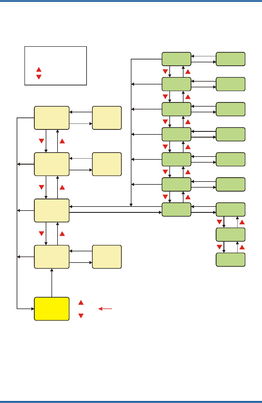
5 MENU SYSTEM
This section details the operation of the menu system for the SDP650 Portable Radio.
The SDP650 radio software uses a programmed menu structure to enable the operator to access
the radio options. The structure of the menu can be configured using the FPP to meet a
customer’s specific needs. In simple configurations, no menu can be programmed. An example
menu structure for a radio is illustrated overleaf in Figure 8.
Pressing the F1 key from the top-level channel screen enters the menu system. The F4 is
generally the “Back” key.
The possible menus are:
• Channel.
• Zone (this is usually the first menu as it is often accessed).
• Contact.
• Radio Info.
• Mute Adjust
• User Options.
• Settings.
• Backlight.
• Brightness.
• Contrast.
• Key Beeps.
• Speaker Volume.
• Alert Volume.
•
• Text Message.
The presence and order of the above menu selections is determined by the FPP configuration.
The Settings menu is a special case entry. Settings is a subgroup that can have any of the list of
menu selections assigned to it. This means that, if required, the lesser used selections can be
partly hidden away under the Setup subgroup but still remain accessible.
The order and presence of the Settings subgroup selections is determined by the FPP. For
instance Info, Radio Status and Contrast could be placed under Settings.
The Options menu group is also a menu subgroup. This subgroup contains the five configuration
options of: Backlight; Brightness; Speaker Volume; Alert Volume; and Key Beeps.
5.1 M
ENU
N
AVIGATION
Pressing the F1 key selects Menu mode from the main Channel Screen. Once in menu mode, the
▼ and ▲ keys cycle through the menus.
To exit Menu mode, press the F4 key or the Menu timeout will exit automatically. Generally,
pressing the F4 key while in a menu backs up to the next highest level of menu and the F1 key
selects the menu option.
SDP650 – USER MANUAL TNM-U-E-0115
Jul 13 (Iss. 1.1) Page 29 MENU SYSTEM
The ▼ and ▲ keys are used to navigate through a list of options such as channels, or to
increase/decrease a value.
Figure 8. Menu Navigation (Example).
Select
Zone
Select
Back
Select
ENTRY POINT = Default Screen
Normal
Channel
Screen
Channel
Back
Back
Back
Back
Back
Back
Back
Back
Back
Back
Back
Back
Back
Back
Back
Back
Back
Back
Back
Back
Menu #1
Zone Select
Note:
Example menus only shown.
Other Menus may be configured with the FPP.
Submenu
Submenu
Submenu
Submenu
Submenu
Submenu
Key Beeps
ON/OFF
Backlight
ON/OFF
(Other User
Menu items)
RSSI
Mute
Adjust
Radio Info
Contrast
Options
Menu #2
Settings Menu
Menu #3
(Optional)
Menu #x
(Optional) Menu #x
Menu #3
Back
Select
F1 Key
F4 Key
Up Key
Down Key
Submenu Selections
Test Mode
Help
Select
Select
Select
Select
Select
Select
Select
Select
Select
Select
SDP650 – USER MANUAL TNM-U-E-0115
Jul 13 (Iss. 1.1) Page 30 MENU SCREENS
6 MENU SCREENS
The menu structure on the SDP650 is configurable using the FPP. A system administrator usually
tailors the order and presence of the menu options to specific customer requirements.
This section describes all the menus that are currently available.
Normally, the menus are divided into three menu lists. These are the Main Menu list, the Setup
Menu list and the User Options Menu list.
In the default configuration, the Main Menu contains the Channel, Zone and Setup menus. This
allows access to the second ‘Setup’ menu level.
The Main Menu can be accessed from the default screen by selecting the F1 button.
To access any of the menu options from the Main, Setup or User Options Menus, use the ▲ and
▼ keys to scroll through the lists until the required menu option is displayed and then press the F1
button.
Pressing the F4 key at any point will go back to the previous screen.
6.1 C
HANNEL
M
ENU
The Channel menu allows the user to select the communication channel to be used within a Zone.
Figure 9. Channel Menu.
The Channel Screen shows the currently selected channel. Use the ▲ and ▼ keys to scroll
through the other available channels and press the F1 key to select it.
Radio channels may be configured with the FPP as specific frequencies or as auto-scan types.
When an auto-scan channel is selected, it will immediately go into scan mode. Selecting another
non-auto-scan channel will stop the scan.
6.2 Z
ONE
M
ENU
The Zone menu allows the user to change Zones. A Zone is normally defined as a group of radio
channels with a common operational role.
Figure 10. Zone Menu.
Use the ▼ and ▲ keys to choose the required Zone. Press the F1 key to select the required
Zone. The radio will return to the default screen and select the first channel in the new Zone.
CHAN
C
1
s
1
ZONE
Zn
01
SDP650 – USER MANUAL TNM-U-E-0115
Jul 13 (Iss. 1.1) Page 31 MENU SCREENS
Direct access to the ‘Zone’ menu from other screens can also be programmed to one of the
function buttons with the FPP.
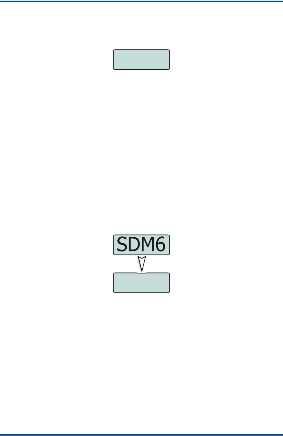
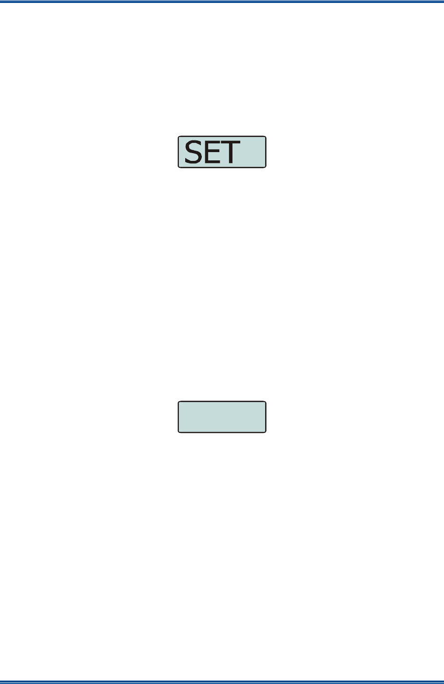
6.3 S
ETUP
M
ENU
The Setup Menu allows the user to access a programmable selection of the menu options. These
menu options can be programmed into the Setup Menu with the FPP. The FPP User can choose
to add any, all or none of the menu options to the Setup menu as required. If the Setup Menu
option is not included in the Main Menu list, the Setup Menu will not be accessible to the radio
user.
Figure 11. Setup Menu.
From the Setup menu screen, press F1 to access the sub-menu options. Using the ▼ and ▲
keys, scroll through the available Setup sub-menu options. Press the F1 key to access the menu
option required.
The Setup menu structure may include, for example:
• Radio Info (Radio software and hardware information);
• RSSI (Received Signal Strength Indication);
• Mute Adjust; or
• Help.
6.4 U
SER
O
PTIONS
M
ENU
The User Options menu allows the user access to a preset selection of menu options for user radio
interface configuration items. These include the backlight timeout period, the backlight brightness,
the display contrast, speaker and alert tone volume control limitations, and the key beeps function.
Figure 12. User Options Menu.
From the User Options menu screen, press F1 to access the sub-menu options. Using the ▼ and
▲ keys, scroll through the available sub-menu items. Press the F1 key to access the menu option
required.
If required, these user option functions can also be assigned directly to the radio’s function buttons.
Information on each of the User Options menu items is contained later in this section.
6.5 M
UTE
A
DJUST
M
ENU
The Mute Adjust menu allows the user to select the threshold at which the radio makes weaker or
distorted received audio signals available to the user.
OPT
SDP650 – USER MANUAL TNM-U-E-0115
Jul 13 (Iss. 1.1) Page 32 MENU SCREENS
Figure 13. Mute Adjust screen.
The default Mute Adjustment range is from 0 – 15. The mute adjustment setting will be applied to
all the radio’s analogue channels.
The SDM600 series radios have a carrier noise mute and it is recommended that a default mute
setting of 4 is used. This means that, with a setting of 4, the mute will open at the point where an
analogue signal is sufficiently noise free to be intelligible.
Other settings are as follows:
• 0 No muting. Allows all decodable signals to the radio user’s audio output device
(loudspeaker, headset etc.).
• 4 Normal default setting.
• 8 Only reasonably strong signals will be heard.
• 15 Only very strong or near perfect signals will be heard.
Use the ▼ and ▲ keys to adjust the mute threshold. Press the F1 key to save the selected mute
setting and return to the previous screen.
Direct access to the ‘Mute Adjust’ screen from other screens can also be programmed to one of
the function buttons with the FPP.
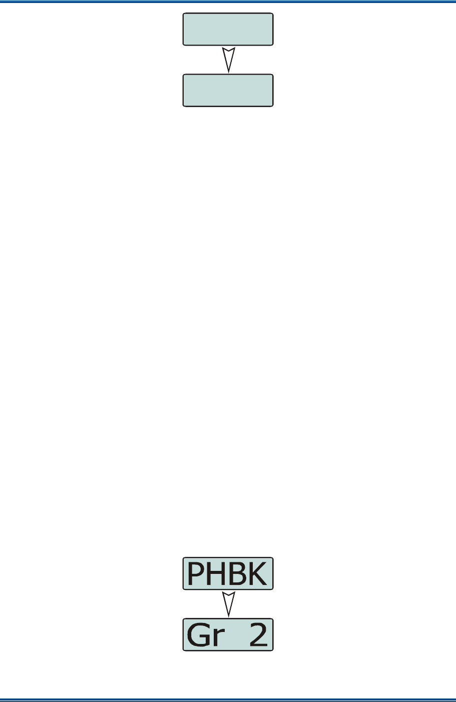
6.6 C
ONTACT
M
ENU
The Contact Menu allows user to select the communication entity they wish to call, e.g. individual
radio unit (UID or SUID), talk group of radio units (TGID), dialled external network access gateway
(phone, internet, other radio networks, dispatchers), and PABX/PSTN.
Up to 20 Contact Lists can be created and programmed into the Radio with the FPP. Each
Contact List can have up to 600 entries. Each Contact List is assigned on a per “Channel” basis in
the Zone set up section of the FPP.
Therefore, the Contact list displayed via the Contact menu is the Contact List assigned to the
radio’s currently selected Channel. This ensures that a user can’t select a Contact who uses a
different mode than the one selected.
Figure 14. Contact Menu screen.
Use the ▼ and ▲ keys to scroll through the available contacts.
4
MUTE
p
SDP650 – USER MANUAL TNM-U-E-0115
Jul 13 (Iss. 1.1) Page 33 MENU SCREENS
Pressing the PTT key will place a call to the selected contact.
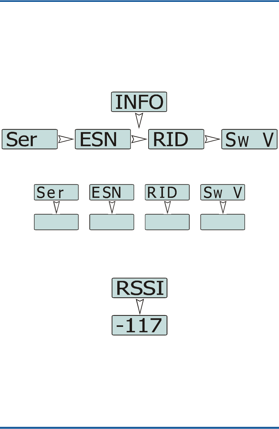
6.7 R
ADIO
I
NFORMATION
The Radio Information menu provides the User with information about the specific radio such as
the Radio ID, Serial Number, Software Version, etc.
The ‘Radio Info’ screens are read-only screens.
Press the F1 key to access the different information screens. Using the ▼ and ▲ keys, select the
required radio information item from the list.
Figure 15. Radio Information Menu.
Press the F1 key to display the specific information screen. Press the F4 key to return to the next
highest menu level.
Figure 16. Radio Information screens.
6.8 RSSI M
ENU
The RSSI menu displays the signal strength of the received RF signal. The current display is in
dBm re 50 Ω and 1 mW, and the reading is typically accurate to within ±2 dBm.
Figure 17. RSSI Menu.
A lower RSSI number indicates a stronger signal, i.e. –80 dBm is a stronger signal than –100 dBm.
6.9 C
ALL
L
OG
The Call Log menu displays the list of received individual call records for the radio. The most
recently received call record is displayed at the top of the list.
0
1
2
V
1
1
1
1
4
2
9
1
0
3
SDP650 – USER MANUAL TNM-U-E-0115
Jul 13 (Iss. 1.1) Page 34 MENU SCREENS
Figure 18. Call Log Menu screen.
The stored record will display either the name of the caller from the phone book or, if the ID is not
known to the Contact list, the user ID will be displayed.
The Call Log list can be used like the Contacts menu to re-call radio entities that have called
before.
The ▼ and ▲ keys can be used to scroll through the Call Log. Pressing the F1 key will display the
details of selected call record.
Pressing the PTT key will place a call to the selected contact.
To return to the previous Menu level, press the F4 key.
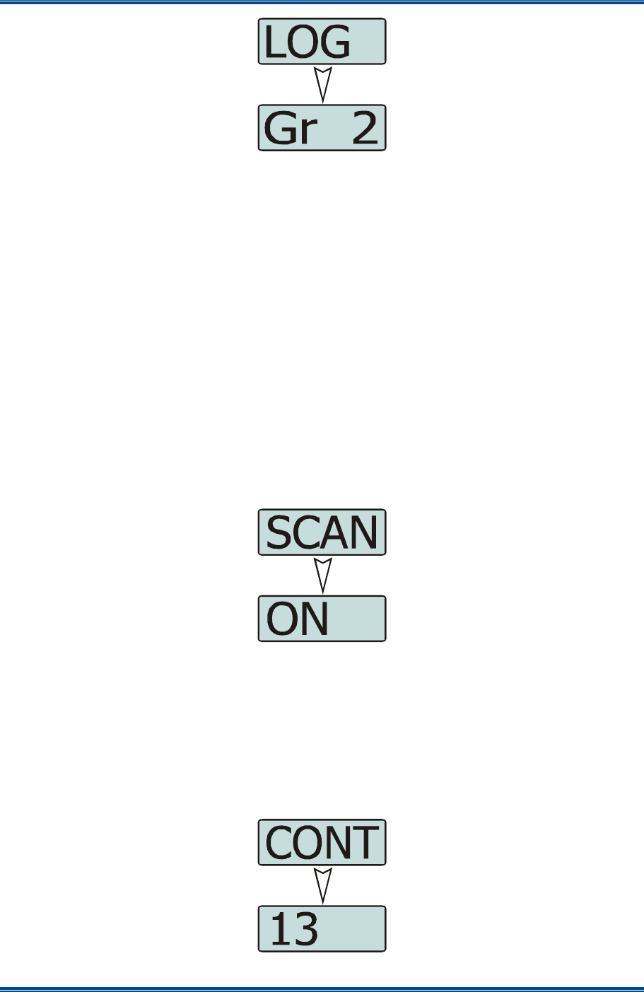
6.10 S
CAN
M
ENU
The Scan menu allows the User to manually start and stop the channel scanning process on the
current channel, if the channel is programmed as a “scan” channel in the FPP.
This Scan function can be programmed to a toggle key.
Figure 19. Scan Menu.
Use the ▼ and ▲ keys to select either the scan On or Off function. Press the F1 key initiate the
action.
6.11 C
ONTRAST
M
ENU
The Contrast menu allows the user to change the “contrast” of control units display (when
adjustable). This optimises the LCD display drives for the best contrast at varying viewing angles
and lighting conditions.
Figure 20. Contrast Menu screen.
p
SDP650 – USER MANUAL TNM-U-E-0115
Jul 13 (Iss. 1.1) Page 35 MENU SCREENS
Use the ▼ and ▲ keys to choose the required contrast level. Press the F1 key to save the
selected contrast level and return to the main default screen.
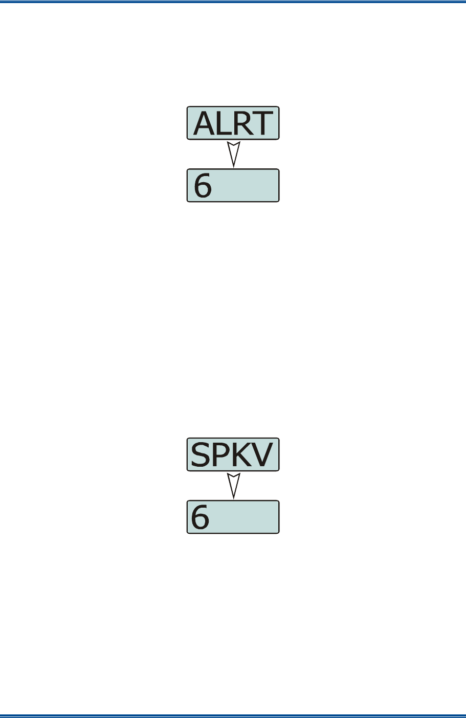
6.12 A
LERT
V
OLUME
M
ENU
This menu allows the user to set the offset of the Alert Volume in relation to the current Volume
setting. Thus, the alert tones can be made louder or softer than the main voice audio.
Figure 21. Alert Volume Menu screen.
The level can be set in 33 steps over the range 0 to 32, with 0 (zero) being about the same as the
voice level.
Use the ▼ and ▲ keys to select the relative alert volume level. A beep will sound at the indicated
level each time the setting is changed.
To accept and save the setting and return to the previous screen, press the F1’ key.
Note.
A minimum Alert Level may be set by the FPP to ensure that the Alerts can always be
heard from the speaker.
6.13 S
PEAKER
V
OLUME
M
ENU
This menu allows the User to set the start-up value of the radio’s audio volume control for user
comfort.
Figure 22 Speaker Volume Menu.
The level can be set in 33 steps over the range 0 to 32, with 0 (zero) delivering no sound, 16 is
normal level and 32 giving the maximum possible output from the speaker.
Use the ▼ and ▲ keys to select the relative speaker volume level. A beep will sound at the
indicated level each time the setting is changed.
To accept and save the setting and return to the previous screen, press the F1 key.
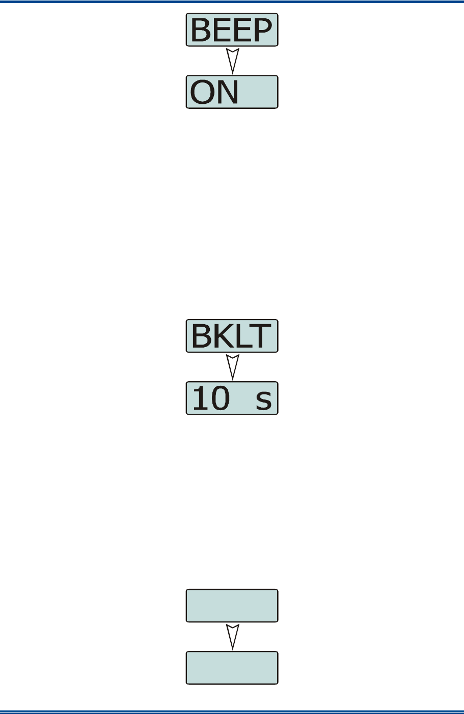
6.14 K
EY
B
EEPS
The Key Beeps menu allows the User to enable or disable the acoustic feedback signals
associated with pressing the function keys on the control unit.
SDP650 – USER MANUAL TNM-U-E-0115
Jul 13 (Iss. 1.1) Page 36 MENU SCREENS
Figure 23. Key Beeps Menu screen.
Use the ▼ and ▲ keys to select the key beeps On or Off as required.
Press the F1 key to initiate the action and return to the main default screen.
6.15 B
ACKLIGHT
The Backlight menu allows the User to select the timeout period of the control unit’s backlight.
When the Backlight is enabled, the control screen will be illuminated whenever there is any user
activity. The backlight will remain on with no further user activity for the set period, after which, the
backlight will turn off.
The maximum backlight timeout period is programmed by the FPP. The numerical values on the
display are in seconds. The choices available for the backlight timeout period are: Always Off;
Always On, 2, 5, 10 and 20 secs.
Figure 24. Backlight Menu screen.
Note.
Received radio traffic events will not prevent the backlight timeout.
Use the ▼ and ▲ keys to select the required backlight timeout period.
To accept and save the setting and return to the previous screen, press the F1 key.
6.16 B
RIGHTNESS
M
ENU
The Brightness menu allows the User to set the intensity of the control unit’s display and key
backlighting where this is possible.
Figure 25. Brightness Menu screen.
16
BRHT

SDP650 – USER MANUAL TNM-U-E-0115
Jul 13 (Iss. 1.1) Page 37 MENU SCREENS
Use the ▼ and ▲ keys to select the required brightness level.
To accept and save the setting and return to the main default screen, press the F1 key.

SDP650 – USER MANUAL TNM-U-E-0115
Jul 13 (Iss. 1.1) Page 38 SPECIAL FUNCTIONS
7 SPECIAL FUNCTIONS
Special functions can be programmed to each of the keys/buttons on the SDP650 Portable Radio
by the FPP. These special functions can be simple short cuts to specific menus or an on/off toggle
facility for specific actions.
7.1 C
HANNEL
U
P
A
ND
D
OWN
These function keys will change the channel in the upward or downward directions.
7.2 Z
ONE
U
P AND
D
OWN
These function keys will change the zone in the upward or downward directions.
7.3 S
CAN
O
N
/O
FF
These function keys will start and stop Scanning.
7.4 S
KIP
The Skip function removes a scan channel from the scan list if the Skip button is pressed while
stopped on that channel. The channel is only restored to the list when the channel is re-selected.
7.5 T
ALK
A
ROUND
O
N
/O
FF
On a repeater channel only, a Talk Around function key allows the radio to transmit on the base
station’s output channel, so the user can talk directly to other mobiles on the channel, while the
repeater is out of service or out of range.
When the key is pressed again (or the Channel is changed) the mobile’s Tx channel reverts to its
normal setting.
Talk Around mode is indicating to the user by a double beep at the start of each PTT.
7.6 L
OW
P
OWER
The Low Power function key forces the radio to low power. Pressing the function button again puts
the radio back to the power level defined for the current channel. The “forced low power state” is
not affected by channel/zone changes.
7.7 G
O
T
O
C
HANNEL
1, 2, 3
OR
4
These functions allow specific zones and channels to be allocated to the keys rather than having to
navigate through the menu system or using the ▲ and ▼ buttons.
7.8 M
ENU
The Menu function key is used for accessing the menu system.
7.9 S
HORTCUTS
These are specific functions that provide direct access to the ‘Channel’, ‘Zone’, ‘Contact’ and ‘Mute
Adjust’ menus.
7.10 R
ESET
The Reset function is usually assigned to the F6 key, and is used as a cancel function when in a
menu or as a backspace when entering keypad dial-strings.

SDP650 – USER MANUAL TNM-U-E-0115
Jul 13 (Iss. 1.1) Page 39 SPECIAL FUNCTIONS
7.11 S
PEAKER
M
UTE
The speaker mute function key will mute the audio output to the speaker. Pressing the function
button again will again allow audio to be heard at the speaker.
7.12 U
NDEFINED
No function is assigned to the relevant key.
7.13 M
AN
D
OWN
The Man Down function provides support for the radio's automatic alarm sequence to be executed
if the radio's inbuilt accelerometer senses certain unusual patterns in the orientation and
movement of the radio.
The detection process uses an orientation "learning" period, immediately after the man down
function is enabled, to establish the how the radio is normally held.
Once this is established, any significant and prolonged deviation from this orientation or an
unexpected acceleration is considered to be an alarm event.
The radio also senses normal walking movement. If this stops for a period of time, this is also
considered an alarm event.
Once the Man Down function is triggered, a warning beep will sound and the operator has a set
time to disarm the sending of an Alarm Status using a programmed "Man Down" button (see
buttons).
The Man Down system sequence is:
•
Radio's man down system is enabled by selecting the Man Down function by pressing the
allocated Man Down button.
•
Radio uses a 3D accelerometer to determine the direction of the gravity's 1 g downward
acceleration. The direction of this force is averaged during the "training" time.
•
Once trained, the gravity component of the acceleration is removed, leaving only
movement, impacts and mis-orientation acceleration to be sensed.
•
User movement is monitored for the normal patterns of acceleration associated with the
walking movement.
•
Mis-orientation is indicated by the gravity force not being cancelled by the "trained" counter-
force.
•
Falls, impacts and other unexpected trauma can be sensed by sudden accelerations that
exceed the force of gravity.
•
If any of these events occur, the Man Down audible alert is triggered.
•
The user has the set time to cancel the alert or the radio will enter the emergency alarm
mode (see Alarm).
Then the Man Down system uses the radio's emergency automatic voice transmission sequencer,
programmed by the Alarm settings, to monitor the audio at the scene of the incident.

SDP650 – USER MANUAL TNM-U-E-0115
Jul 13 (Iss. 1.1) Page 40 SPECIAL FUNCTIONS
7.14 L
ONE
W
ORKER
Lone Worker is used to initiate emergency alarm mode when the user is unresponsive after a
predetermined time. A data message is also sent to the device management software (via the
gateway) indicating that the worker may be incapacitated.
The Lone Worker countdown is reset after any user activity with the radio- either PTT or “Lone
Worker” button are pressed.
7.15 DMR A
LL
C
ALL
This function is used as a short sequence of key presses for “All Call” dial string (******#). In order
to initiate All Call. The user should press PTT within 5 seconds after “DMR All Call” button is
pressed.
7.16 D
IAL
S
TRINGS
The dial plan specifies a sequence of digit number in contact list that can be programmed in
SDP650, via FPP, to initiate connectivity to a remote party using another terminal in the network.
Additionally, Dial Strings may be entered to alter a terminal’s behaviour or configuration without
initiating a call.
In the SDP650, Dial Strings may only be stored in the contacts lists.

SDP650 – USER MANUAL TNM-U-E-0115
Jul 13 (Iss. 1.1) Page 41 ACCESSORIES
8 ACCESSORIES
The accessories that are available for the SDP650 Portable Radio are listed below in Table 5.
Contact Simoco for further information.
Table 5. SDP650 DMR Portable Radio Accessories.
Part No. Description Notes
PAR-600BATL2 SDP Standard 2200 mAh Li-ion Battery
PAR-600BATL3* SDP High Capacity 3000 mAh Li-ion
Battery
* Available Q2 2013
PAR-9180LMS2-2 Speaker Microphone with two buttons
Combined speaker and microphone for
light duty use incorporating two
programmable function keys.
PAR-600LMS4 Speaker Microphone with four buttons
Combined medium duty speaker and
microphone incorporating four
programmable function keys.
PAR-9180LMW1 Speaker Microphone – IP67
TBC* SDP Standard Case
* Available Q2 2013
TBC* SDP Heavy Duty Case
* Available Q2 2013
PAR-600CRG1 SDP Single Charger Unit
Excludes Power Supply (PA-ADAPTOR)
Charger capable of charging one
portable radio at a time.
PA-ADAPTOR-UK SDP Single Charger PSU UK
230 V AC with 3 pin UK fitting
PA-ADAPTOR-EU SDP Single Charger PSU EU
230 V AC with 3 pin EU fitting
PA-ADAPTOR-SA SDP Single Charger PSU SA
230 V AC with 3 pin SA fitting
PA-PSU1A5 SDP Single Charger PSU
Excludes Mains Cord (PA-ACCORD-
XX8)
PAR-600CRG2 SDP Dual Charger Unit
Excludes Power Supply (PA-PSU3A0) Charger for two portable radios
PA-PSU-3A5 SDP Dual Charger PSU
PA-ACCORD-UK8 UK Mains Cord for PA-PSU3A0
IEC C7 to UK 3 Pin, 1.8 m
PA-ACCORD-EU8 EU Mains Cord for PA-PSU3A0
IEC C7 to Euro 2 Pin, 1.8 m
PA-ACCORD-SA8 SA Mains Cord for PA-PSU3A0
IEC C7 to SA 3 Pin, 1.8 m
PAR-600GRG6* SDP Six Way Charger with separate
Power Supply
Charger for up to six portable radios.
* Available Q2 2013
6102 500 00531 VHF helical Stubby Antenna
136 MHz – 174 MHz.
* Available Q2 2013
6102 500 00541* VHF Moulded Helical Antenna
Un-cut 136 Mhz – 174 MHz (includes
cutting chart).
* Available Q2 2013
6102 500 00431 UHF Whip Antenna ¼ Wave
400 MHz – 480 MHz (Green)
6102 500 00441 UHF Helical Antenna
400 MHz – 440 MHz (Orange)
6102 500 00451 UHF Helical Antenna
435 MHz – 485 MHz (White)
PAR-600CLIP SDP 2.5” Belt Clip
Belt Clip for belt widths of up to 50 mm.
The clip slots onto the rear of the battery.
PA-LMEP SDP 1 wire Surveillance Kit
(Rx only)
PA-ACON SDP Antenna to BNC Adapter

SDP650 – USER MANUAL TNM-U-E-0115
Jul 13 (Iss. 1.1) Page 42 ACCESSORIES
Part No. Description Notes
PAR-9180PRLDU SDP Programming Lead USB
Universal Serial Bus (USB) programming
lead for use with the FPP when
configuring the radio.
SA-600IMD Intelligent Man-Down License
SA-600MST* Multi-Site Trunking License
* Available Q2 2013

SDP650 – USER MANUAL TNM-U-E-0115
Jul 13 (Iss. 1.1) Page 43 APPENDIX A
APPENDICES
A1 ALERT TONES AND MESSAGES
A
LERT
T
ONES
The Alert Tones supported by the SDP600 Series Portable Radios are listed below in Table A1.
Table A1. Alert Tones.
Tone Frequency, Tone Duration,
Repeats Description
Key Beep 940 Hz 60 ms Generated by key presses. Key Beeps can be
enabled or disabled in the FPP.
Also used when Rotary Knob is changed.
Error Beep 440 Hz 50 ms x5 Generated by invalid key or unsuccessful radio
events.
Normal Alert 440 Hz 320 ms If attempt to skip channel if only 1 remaining channel
in scan group.
Power-Off
Complete
880 Hz 1 sec Alert tone generated after radio saves its data and is
ready to power down.
PTT Grant 1000 Hz 30 ms Generated after PTT request granted and radio
starts transmitting.
Call Alert 2000 Hz 100 ms x5 When receiving a message.
Emergency 600 Hz 160 ms, 1800 Hz 100 ms Generate a short confidence beep when alarm mode
is activated. This short beep can be
enabled/disabled in FPP.
Man Down 1000 Hz 100 ms, 1152 Hz 100 ms
1400 Hz 100 ms, 1600 Hz 100 ms
Generate at low volume during after FPP defined ‘Tilt
Delay’. If Man-Down still down, then generate at full
volume for FPP defined ‘Alert Delay’ period.
Times UP
Alert
(940 Hz 60 ms, 0 Hz 1 sec) x5 5 short beeps repeated at 1 second intervals.
Used 5 sec before Transmit limit timer expires.
Used 5 sec before Lone Worker time limit expires.

SIMOCO GROUP
Global Headquarters: Field House, Uttoxeter Old Road, Derby DE1 1NH
UK: Tel: 08717 411 050
Fax: 08717 411 049
International: Tel: +44 (0) 1332 375 671
Fax: +44 (0) 1332 375 672
www.simocogroup.com