Simoco Wireless Solutions SDP600UW UHF Portable Transceiver User Manual 2
Simoco Australasia Pty Ltd UHF Portable Transceiver 2
UserManual.wiki
>
Simoco Wireless Solutions
>
SDP600UW User Manual
>
User Manual 2
Contents
1.
User Manual 1
2.
User Manual 2
User Manual 2
Navigation menu
Upload a User Manual
Namespaces
Wiki Guide
HTML
PDF
Info
Views
User Manual
Discussion / Help
Navigation
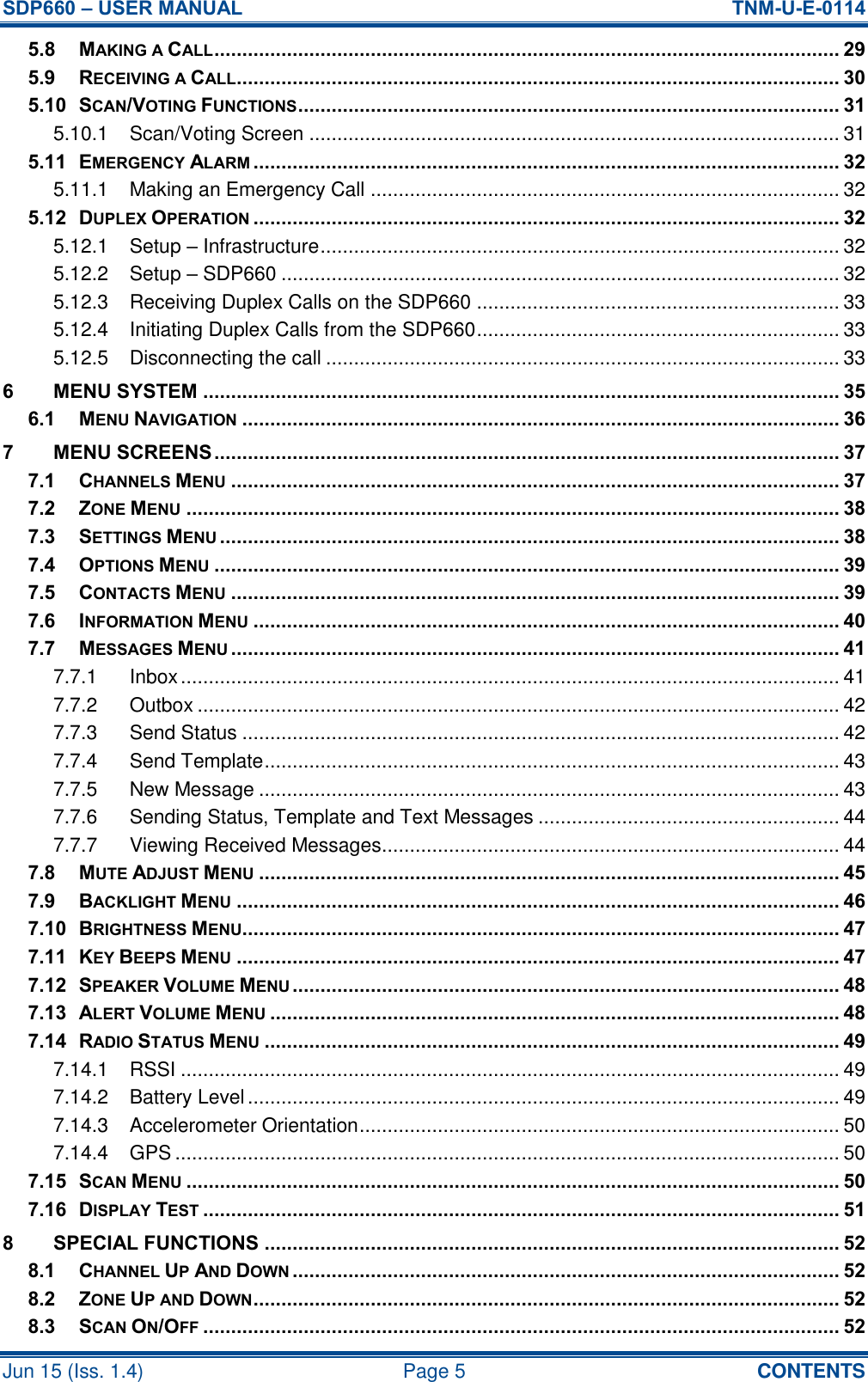
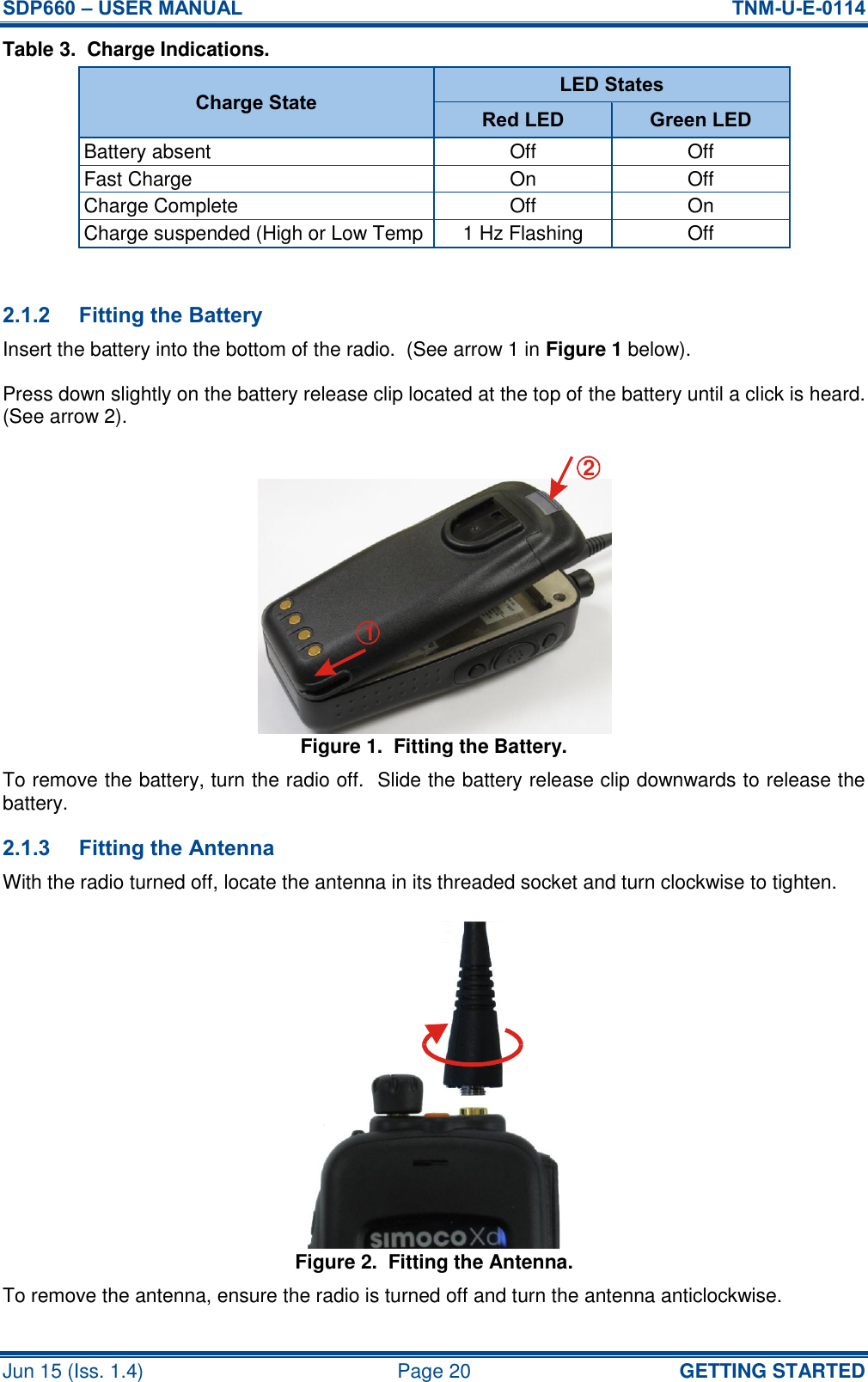
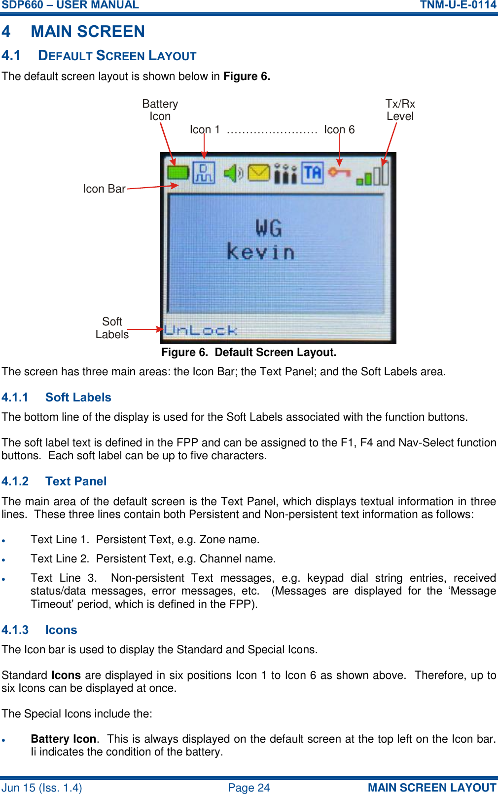
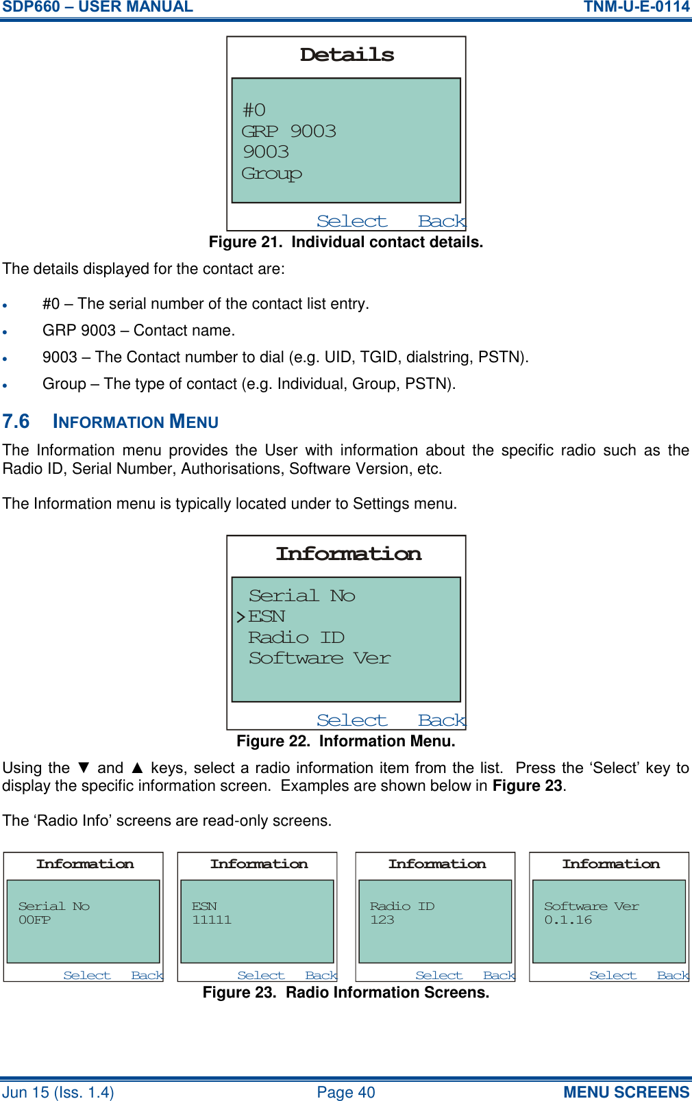
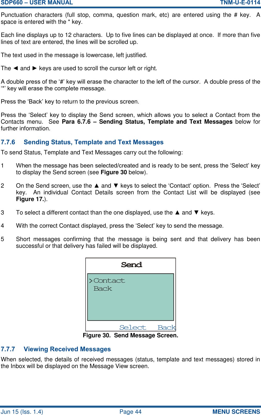
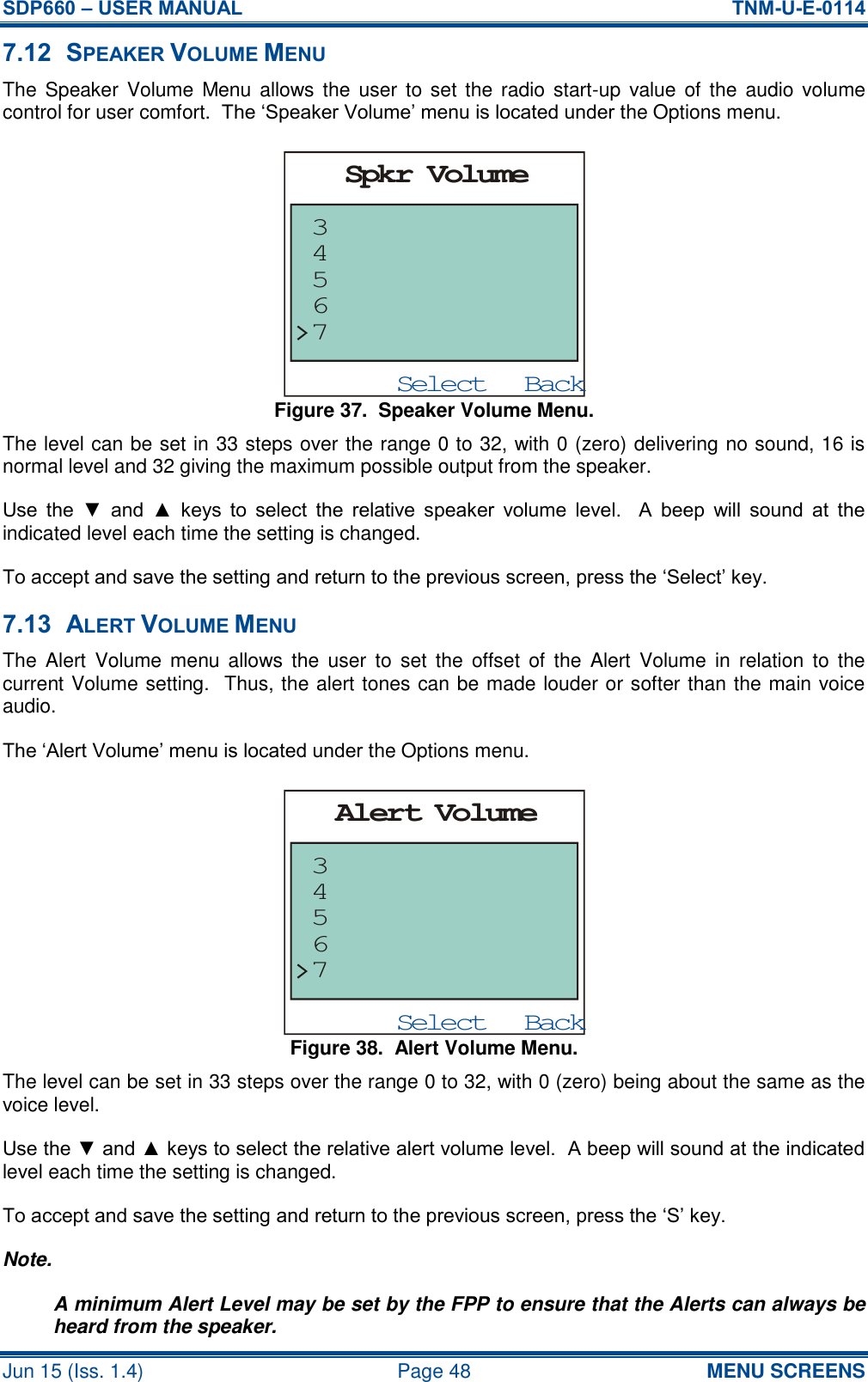
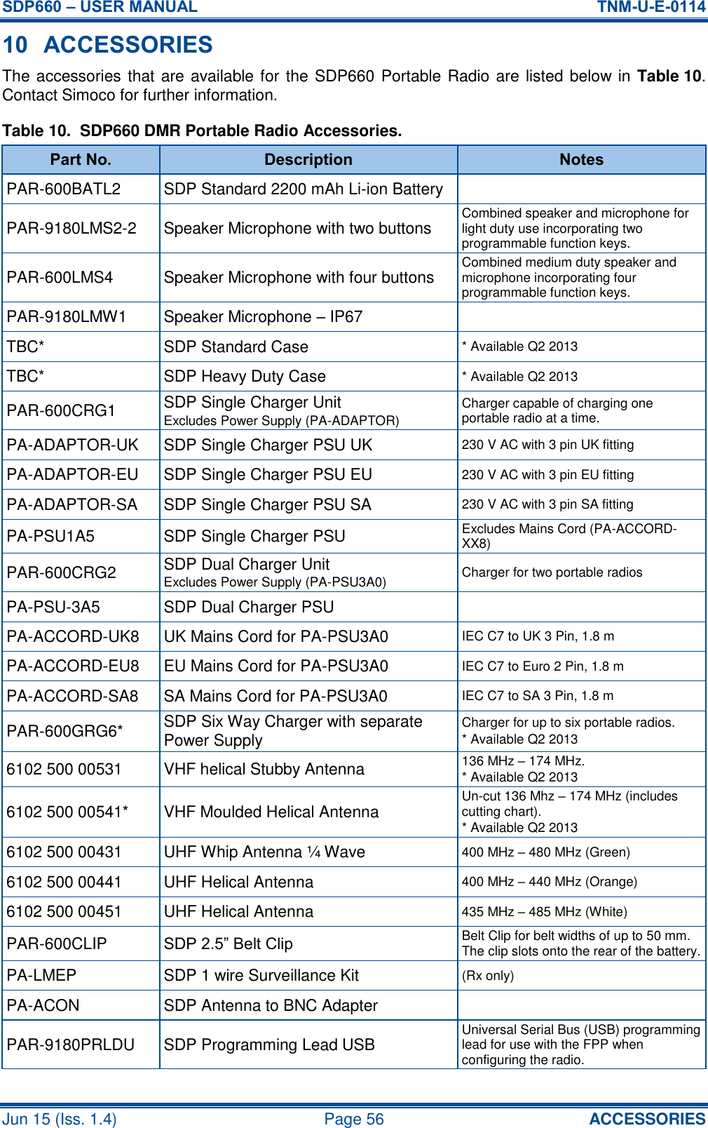
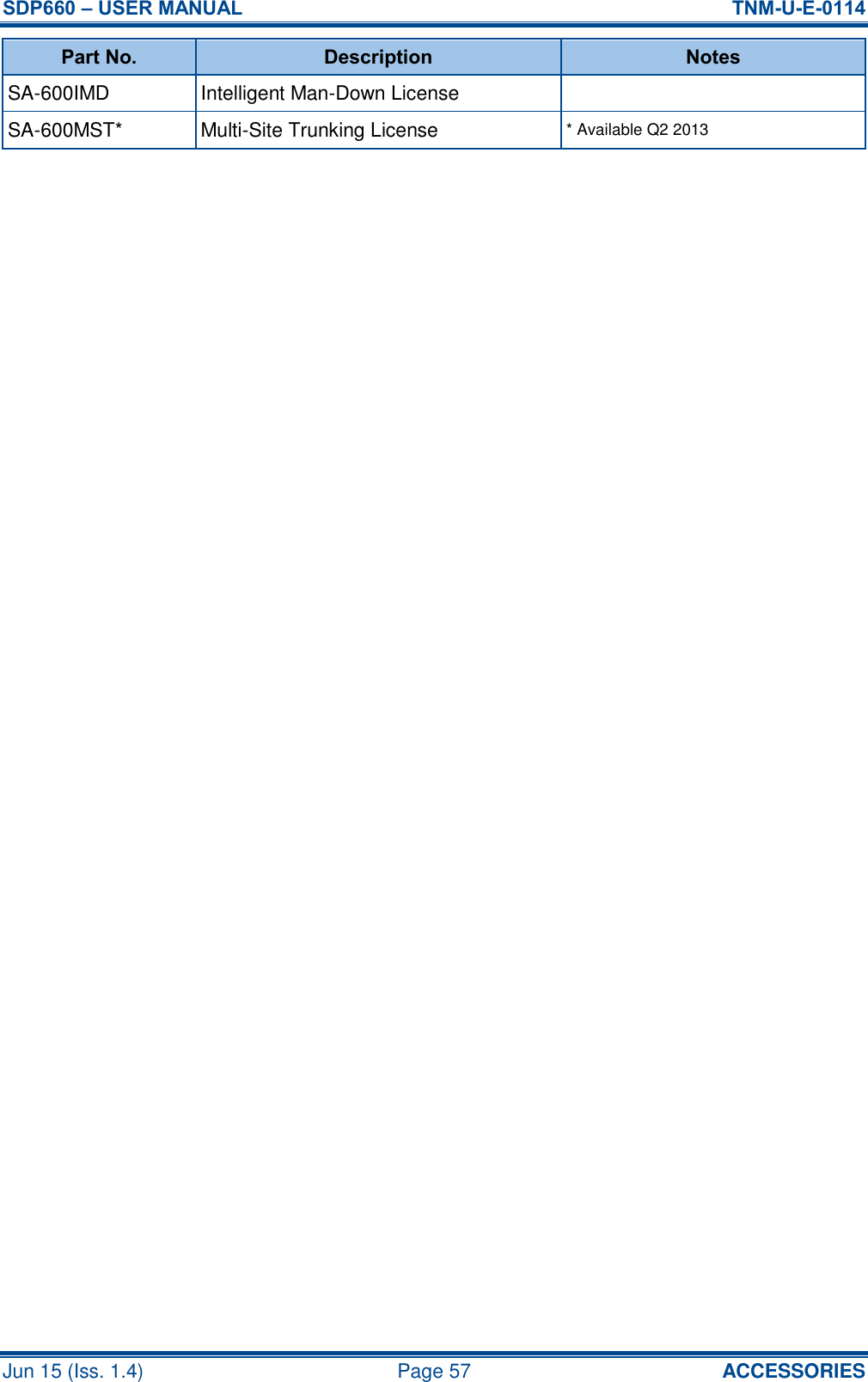
![SDP660 – USER MANUAL TNM-U-E-0114 Jun 15 (Iss. 1.4) Page 19 GETTING STARTED 2 GETTING STARTED This User Manual covers the basic operation of the Simoco SDP660 Digital Portable radio. The radio is software programmable and can be customised to the operational requirements of a customer’s specific needs. Simoco representatives can help in programming the radio facilities to meet a customer’s present and future requirements. Users should check with their Simoco dealer or system administrator about the features programmed into the radio and specifically about: Whether any preset conventional channels are programmed into the radio? Which buttons have been programmed to access other features? The optional accessories that may be required? 2.1 PREPARING THE RADIO FOR USE 2.1.1 Charging the Battery WARNING LITHIUM BATTERIES. THIS EQUIPMENT USES LITHIUM ION BATTERIES. REFER TO THE PERSONAL SAFETY PAGES. Your radio is powered by a 2200 mAh Lithium Ion battery. To avoid damage and comply with warranty terms, the battery should be charged with a Simoco Standard Battery charger. For best performance, new batteries should be charged for 5 hours before initial use. 2.1.1.1 Procedure This charging procedure assumes that the PAR-600CRG1 Single Rapid Charger is used. For full details on this charger, please refer to TNM-U-E-0118, PAR-600CRG1 Single Rapid Charger – SDP650/660 Instructional Manual [3]. 1 Connect the AC power adapter to an AC mains supply and to the socket on the back of the charger. 2 Switch on the mains power. The Red LED on the charger will flash briefly. The charger is now in standby mode. 3 Switch the radio off. 4 Place the battery pack, or the radio with the battery attached, into the charging slot on the charger. 5 Check that the Red LED on the charger is illuminated. 6 The fast charging process will be initiated. When the battery pack is fully charged, the Green LED on the charger will be illuminated (see Table 3 overleaf).](https://usermanual.wiki/Simoco-Wireless-Solutions/SDP600UW.User-Manual-2/User-Guide-2647672-Page-19.png)