Simoco Wireless Solutions SRM9000AC VHF MOBILE TRANSMITTER User Manual SRM9000 Service Manual 231104
Simoco Australasia Pty Ltd VHF MOBILE TRANSMITTER SRM9000 Service Manual 231104
Contents
- 1. USERS MANUAL 1
- 2. USERS MANUAL 2
- 3. USERS MANUAL
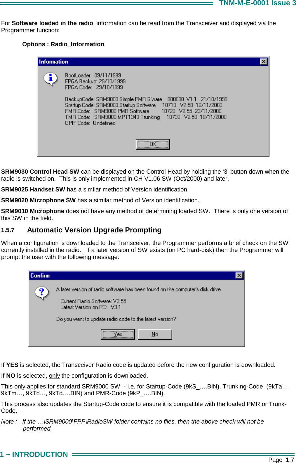
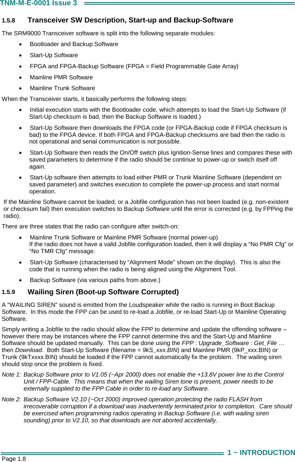
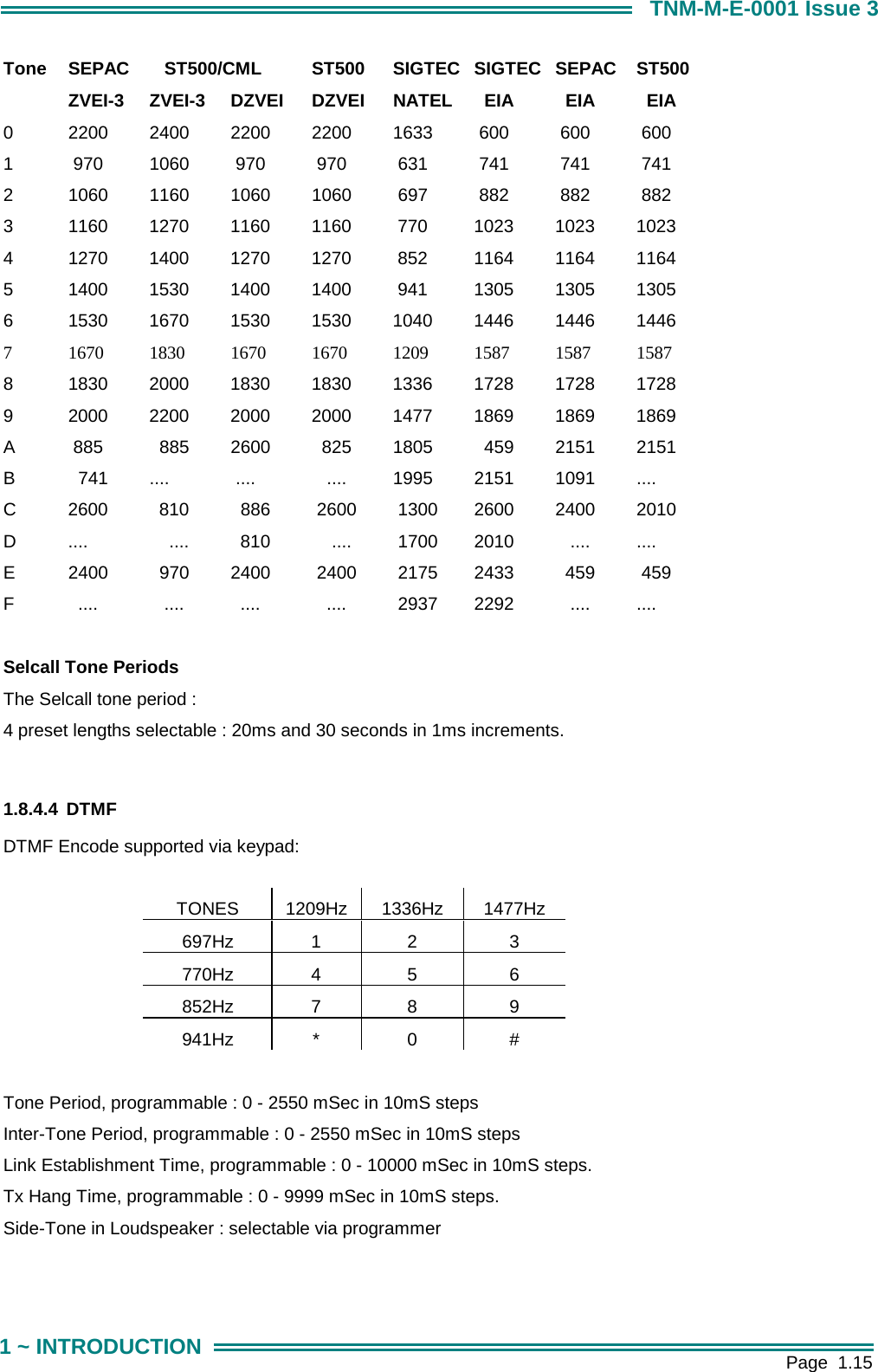
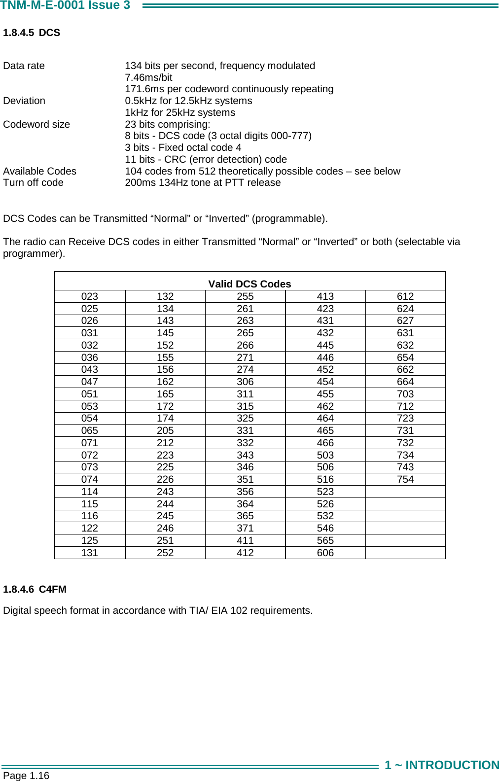
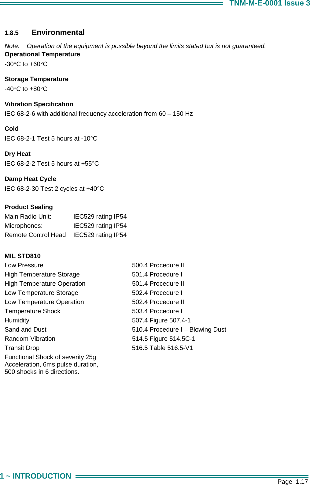
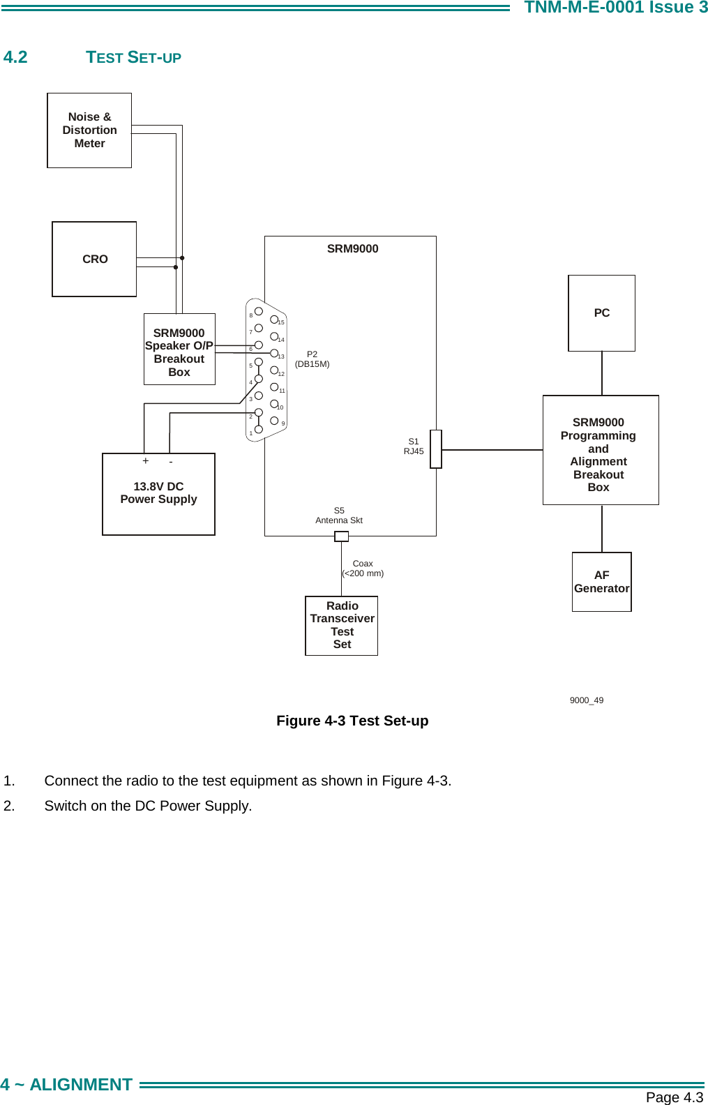
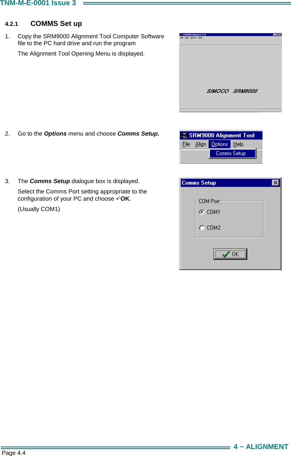
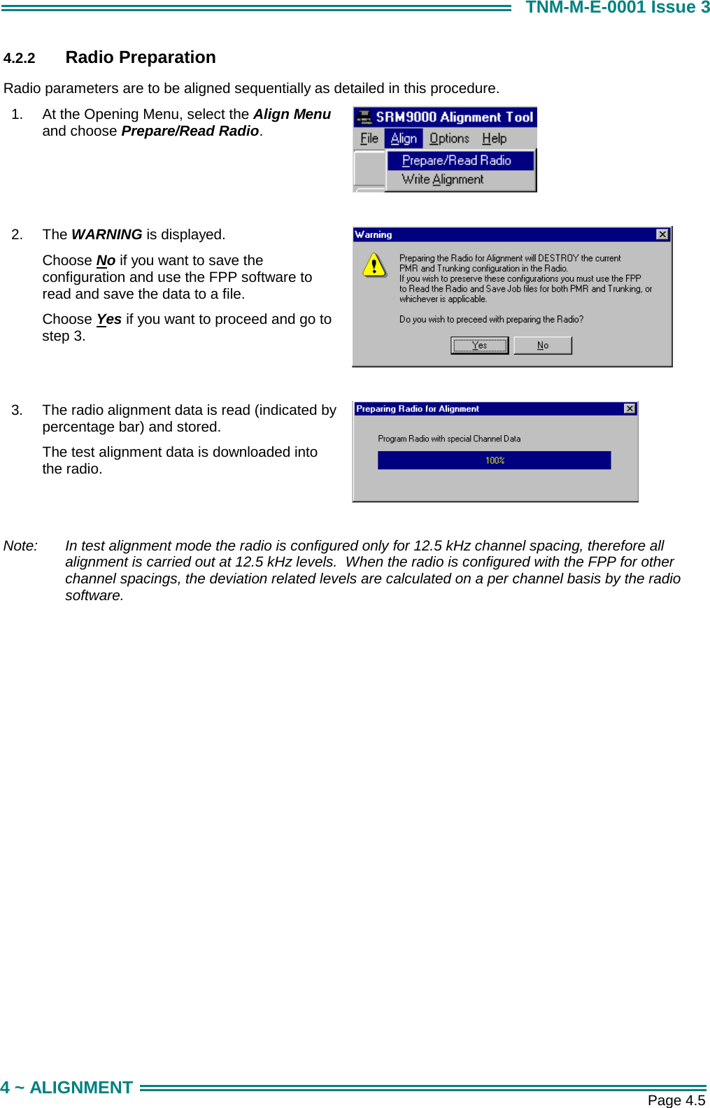
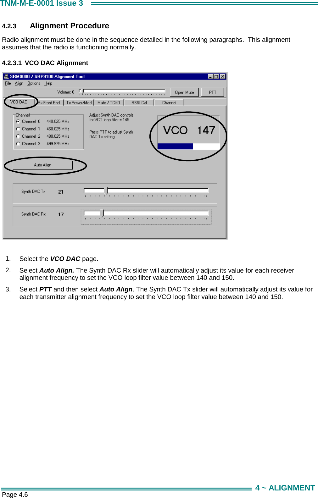
USERS MANUAL 1