Simoco Wireless Solutions SRM9000TU UHF MOBILE TRANSCEIVER User Manual USERS MANUAL
Simoco Australasia Pty Ltd UHF MOBILE TRANSCEIVER USERS MANUAL
Contents
- 1. SERVICE MANUAL
- 2. USERS MANUAL
USERS MANUAL
SRM9022
Mobile Radio
Conventional – PMR
Operating Instructions
TNM-U-E-0063 Issue 2
March 2007
TMC Radio Pty. Ltd.
1270 Ferntree Gully Road
Scoresby
Victoria, 3179
Australia
ISO9001 Lic.QEC20848
SAI Global

SRM9022 ~ PMR MOBILE RADIO USER GUIDE
© TMC Radio 2007 page 2 TNM-U-E-0063 Issue 2
ASSOCIATED DOCUMENTATION
The following documentation is available for use with the SRM9000 series of
products:
TNM-I-E-0005 SRM9000 Series Installation Instructions
TNM-M-E-0001 SRM9000 Service Manual
TNM-U-E-0012 SRM9020 Trunked Operating Instructions
TNM-U-E-0013 SRM9020 PMR Operating Instructions
TNM-U-E-0004 SRM9030 Trunked Operating Instructions
TNM-U-E-0003 SRM9030 PMR Operating Instructions
To order copies of any of the above publications, or any other TMC Radio product,
contact TMC Radio on +61 3-9730-3800 or send a Fax on +61 3-9730-3968.
ABOUT THIS DOCUMENT
This publication is copyright and no part may be reproduced without prior permission
of TMC Radio.
Due to our policy of continuous improvement to our products and services, technical
specifications and claims, correct at time of publication, may be subject to variation
without prior notice.
TMC Radio has endeavoured to ensure that the information in this document is fairly
and accurately stated, but does not accept liability for any errors or omissions.

SRM9022 ~ PMR MOBILE RADIO USER GUIDE
© TMC Radio 2007 page 3 TNM-U-E-0063 Issue 2
SAFETY
1. Do NOT operate your radio, without a handsfree kit, whilst driving a
vehicle.
2. Do NOT operate your radio in an explosive atmosphere.
Obey the 'Turn Off Two-way Radios' signs where these are posted, e.g.
on a petrol station forecourt.
3. Do NOT touch the antenna while the radio is transmitting.
4. Do NOT operate the radio if the antenna has become disconnected or
damaged.
HINTS FOR USING THE RADIO
• When speaking, hold the microphone a few centimeters from your mouth and
speak across it, rather than into it.
• Keep the length of your conversation to a minimum and replace the microphone
on its cradle after use.
• When it is possible to move location, avoid making calls from known poor signal-
strength areas such as the radio systems fringe areas (limit of range) or from
screened or shadowed areas, e.g. an underground car park or underpass.
• To avoid unnecessary drain on the vehicle battery, keep the engine running when
using the radio for extensive periods of time.

SRM9022 ~ PMR MOBILE RADIO USER GUIDE
© TMC Radio 2007 page 4 TNM-U-E-0063 Issue 2
CONTENTS
1. INTRODUCTION .................................................................................................7
1.1 Overview......................................................................................................7
1.2 Installation...................................................................................................7
1.3 Conventions................................................................................................7
2. FRONT PANEL CONTROLS ..............................................................................8
3. MENU SYSTEM...................................................................................................9
3.1 Menu Navigation.........................................................................................9
4. MAIN MENU SCREENS....................................................................................11
4.1 Channels Screen.......................................................................................11
4.2 Phonebook Screen ...................................................................................12
4.3 Status Screen............................................................................................12
4.4 Send Message Screen..............................................................................13
4.5 Stored Calls Screen (Selcall) ...................................................................14
4.6 Stored Calls Screen (Data Messages).....................................................15
4.7 Setup Screen.............................................................................................16
5. COMMON FUNCTIONS AND FACILITIES .......................................................17
5.1 Switch-On/Switch-Off...............................................................................17
5.1.1 Volume Adjustment ................................................................................. 17
5.2 Receiving...................................................................................................17
5.3 Transmitting..............................................................................................18
5.4 SELCALL Functions.................................................................................19
5.4.1 Receiving a Selcall.................................................................................. 19
5.4.2 Sending a Selcall .................................................................................... 19
5.4.3 Other Selcall Functions ........................................................................... 19
5.5 Scan Functions.........................................................................................20
5.5.1 Scan Screen............................................................................................ 20
5.5.2 Scan-Edit Screen .................................................................................... 21
5.6 DTMF Operation........................................................................................22
5.7 External alert.............................................................................................22
5.8 Auxiliary Output........................................................................................22
6. SETUP...............................................................................................................23
6.1 Setup Sub-Menus .....................................................................................23
6.1.1 User Options ........................................................................................... 23
6.1.2 Mute Adjust ............................................................................................. 24
6.1.3 Contrast................................................................................................... 24
6.1.4 Alert Volume............................................................................................ 24

SRM9022 ~ PMR MOBILE RADIO USER GUIDE
© TMC Radio 2007 page 5 TNM-U-E-0063 Issue 2
6.1.5 Radio Information.................................................................................... 25
6.1.6 Phone Book Menu................................................................................... 25
6.1.7 Phone Book Edit Menu ........................................................................... 26
6.1.8 Mode Selection ....................................................................................... 28
7. SPECIAL FUNCTION BUTTONS......................................................................29
7.1 Monitor.......................................................................................................29
7.2 Squelch Defeat..........................................................................................29
7.3 Reset..........................................................................................................29
7.4 Scan...........................................................................................................29
7.5 Auxiliary.....................................................................................................29
7.6 Send-2........................................................................................................29
7.7 Transpond .................................................................................................29
7.8 CTCSS .......................................................................................................29
7.9 Mute ...........................................................................................................29
7.10 External Alert.........................................................................................29
7.11 Goto Chan A, B, C, D.............................................................................29
7.12 Special Enc 1…8 ...................................................................................29
7.13 Alarm......................................................................................................29
7.14 Repeater Defeat.....................................................................................29
7.15 Low Power .............................................................................................30
7.16 DTMF Mode............................................................................................30
7.17 Scrambler On/Off ..................................................................................30
7.18 Send DTMF1/2 .......................................................................................30
7.19 Lock / Unlock Key .................................................................................30
8. OPTIONS...........................................................................................................31
8.1 Quick Release Transceiver Kit (MA-QRCRADLE)..................................31
8.2 Microphone/Control Head Extension Lead.............................................31
8.3 Type 1 Parallel I/O Expansion Option .....................................................31
8.4 Internal GPS Option..................................................................................31
8.5 Cross-linked Cable ...................................................................................31
8.6 600 Ohm Interface Option ........................................................................31
8.7 Type 2 I/O Option......................................................................................31
8.8 Dual Control Head Option........................................................................31
8.9 Dual Transceiver Option ..........................................................................31
8.10 Desk Top Base Kit.................................................................................31
9. TROUBLESHOOTING ......................................................................................32

SRM9022 ~ PMR MOBILE RADIO USER GUIDE
© TMC Radio 2007 page 6 TNM-U-E-0063 Issue 2
10. APPENDIX A - ALERT TONES AND MESSAGES.......................................34
11. APPENDIX B - GLOSSARY ..........................................................................35
12. APPENDIX C – COMPLIANCE WITH RF ENERGY EXPOSURE
GUIDELINES (UNITED STATES AND CANADA) ...................................................36

SRM9022 ~ PMR MOBILE RADIO USER GUIDE
© TMC Radio 2007 page 7 TNM-U-E-0063 Issue 2
1. INTRODUCTION
1.1 OVERVIEW
The SRM9000 Series Radios are versatile Digital Signal Processor (DSP) controlled,
two-way mobile radios. The SRM9000 Series is available in a number of frequency
bands and versions for specific applications. This manual describes the operation of
the SRM9022 PMR Controller Microphone variant.
The radio consists of a Transceiver unit that may be mounted in the vehicle boot or
under a seat, and a Controller Microphone, which is designed to mount on the
vehicle console or within view and reach of the operator.
The radio is software programmable and can be customised to the operational
requirements of your particular fleet. Your TMC Radio representative can help in
programming your radio facilities to meet your present and future requirements.
This guide describes the facilities that are currently available and can be
programmed into the SRM9022.
1.2 INSTALLATION
As the installation of your SRM9022 Radio is a technical and possibly hazardous
operation, we recommend that it is installed and set up for use by your dealer or an
authorised installer. However, if you need information regarding the correct
procedures for installation, please refer to the SRM9000 Series Installation
Instructions supplied with the radio.
1.3 CONVENTIONS
Where the word “generally” or “may” is used to describe a facility, this operation is an
option that may be enabled with the Radio Field Personality Programmer (FPP).
SRM9022 ~ PMR MOBILE RADIO USER GUIDE
© TMC Radio 2007 page 8 TNM-U-E-0063 Issue 2
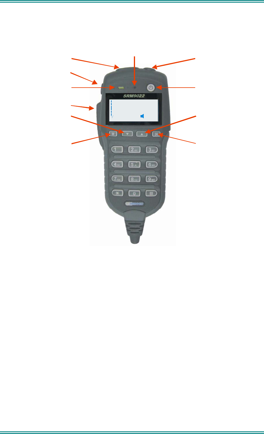
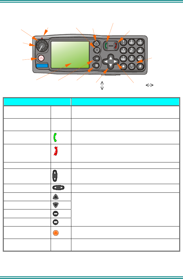
2. FRONT PANEL CONTROLS
Power On/Off
Function #5 (F5)
Volume Up/Down
Function #6 (F6)
RX/TX LED
Microphone
Push To Talk
Menu or
Function #1 (F1)
Function #2 (F2)
Dow n or Up &
Function #3 (F3)
OK &
Function #4 (F4)
501
Mt Oberon
ME NU SCA N
Figure 2-1 SRM9022 Controller Mic. Key Layout

SRM9022 ~ PMR MOBILE RADIO USER GUIDE
© TMC Radio 2007 page 9 TNM-U-E-0063 Issue 2
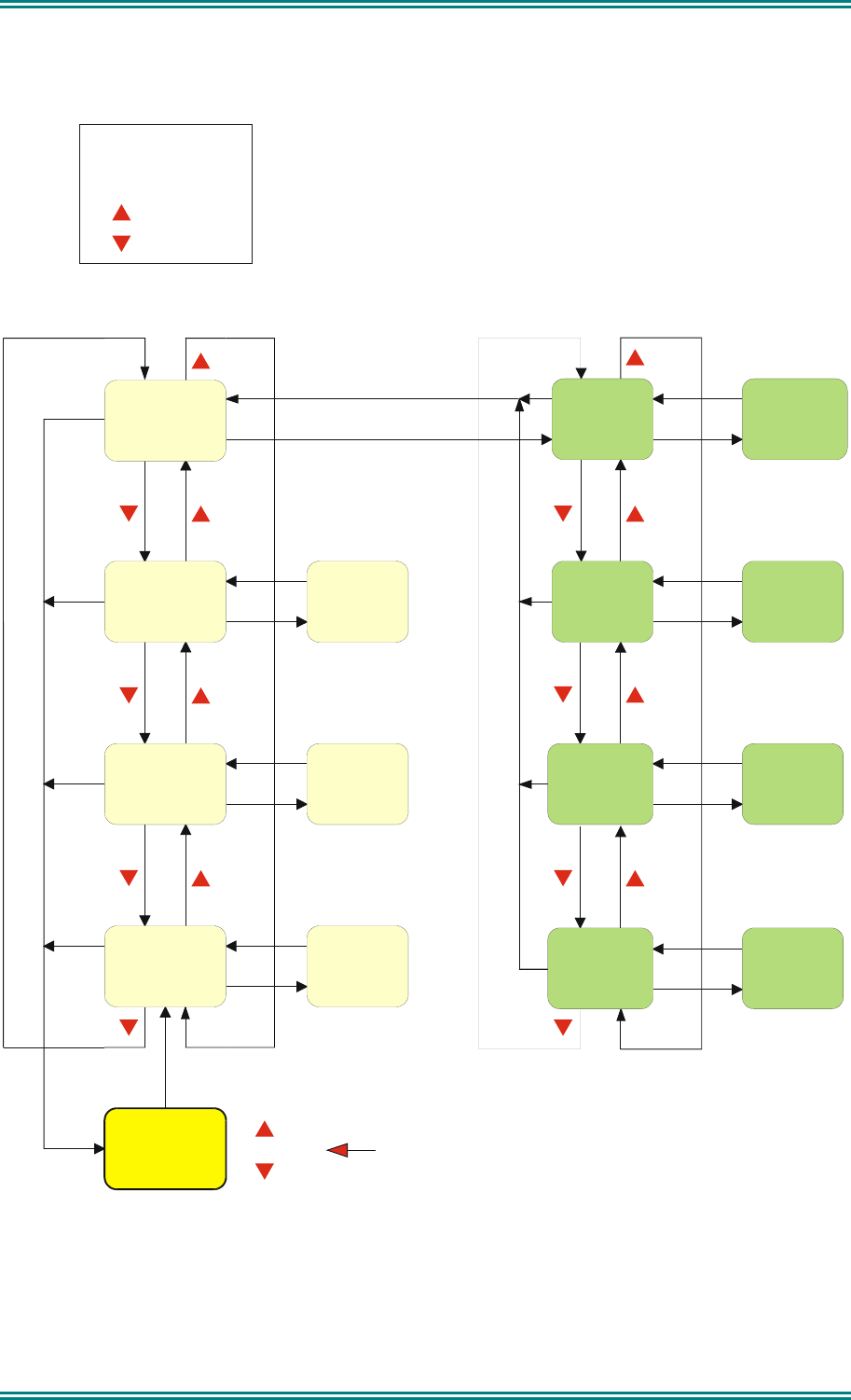
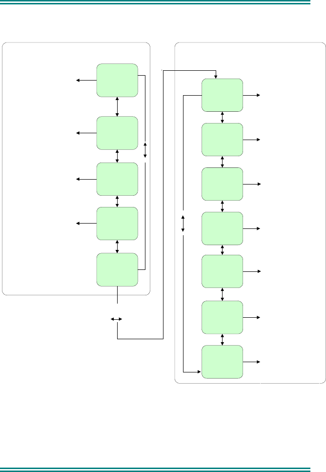
3. MENU SYSTEM
The SRM9022 radio software uses a programmed Menu structure to enable the
operator to access the radio options. The structure of the menu can be programmed
to meet the specific needs of individual customers.
Figure 3-1 (overleaf) illustrates the menu structure of the radio. Note that the order
and presence of each menu is determined by the configuration of the radio
programmed by the Field Programmer.
There are setup sub-menus that provide access to radio setup parameters.
Possible Menu entries are:
• Phone Book
• Status
• Stored Calls
• Mute Adjust
• Send Message
• Setup
• Phone Book Edit
• Contrast
• Alert Volume
• Radio Information
• Mode Selection
• Received Signal Strength Indication (RSSI)
To assist the user in menu key selection, a soft menu label will often appear above
the function keys. The label shows the user the current function for that key which
may change between different menus.
Programming of menus is a configuration task normally performed by the system
manager using FPP software.
3.1 MENU NAVIGATION
The “M” key is generally used to select Menu mode from the main Channel Screen.
Once in Menu mode, the ▲ and ▼ keys cycle through the menus.
To exit Menu mode, press the “M” key again or the Menu timeout will exit
automatically. Generally, pressing “M” key while in a menu backs up to the next
highest level of menu and the “OK” button selects the function.
The ▲ and ▼ keys are generally used to navigate through a list of options such as
channels, or increase/decrease a value.
SRM9022 ~ PMR MOBILE RADIO USER GUIDE
© TMC Radio 2007 page 10 TNM-U-E-0063 Issue 2
Channel
Screen
Phonebook
Menu #1
Status
Menu #2
Stored Calls
Menu #3
Setup
Menu #4
Lists Users
and Names
List of
Status
Selections
SubMenu #3
SubMenu #4
Alert
Volume
Phone Book
Edit
User
Options
Contrast
ENTRY POINT = Default Screen
Channel
List / Delete
Stored
Calls
Note: Example Menus only shown.
Other Menus may be configured with the FPP
Up Key
Down Key
M Key
OK Key
SubMenu #1
SubMenu #2 SubMenu
#X
Screen
Phone Book
Edit
Screen
User
Options
Screen
Alert
Volume
Screen
M
OK
M
M
M
M
M
OK
OK
M
M
OK
OK
M
M
M
OK
OK
M
M
M
OK
M
OK
M
Figure 3-1 Menu Navigation
SRM9022 ~ PMR MOBILE RADIO USER GUIDE
© TMC Radio 2007 page 11 TNM-U-E-0063 Issue 2
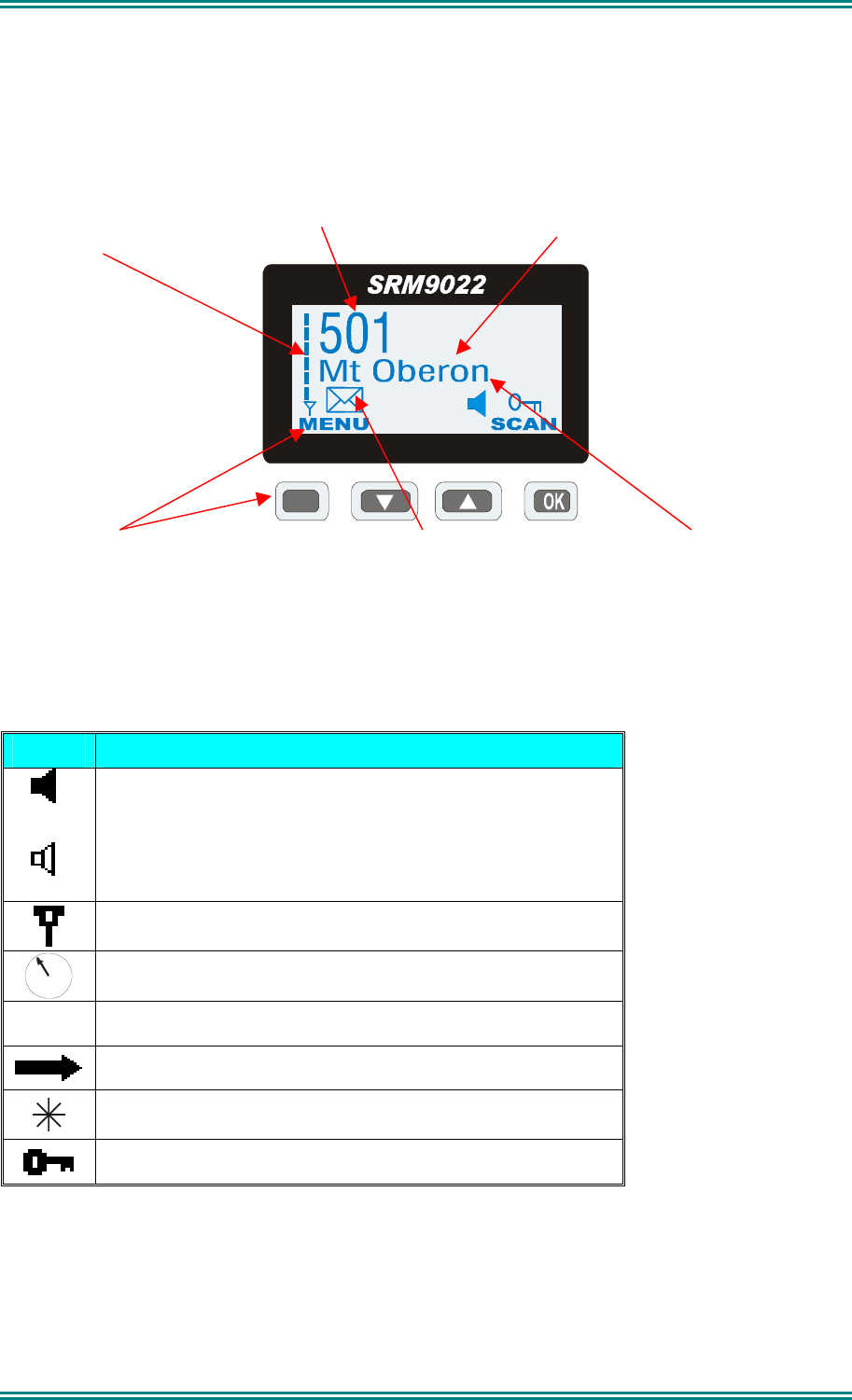
4. MAIN MENU SCREENS
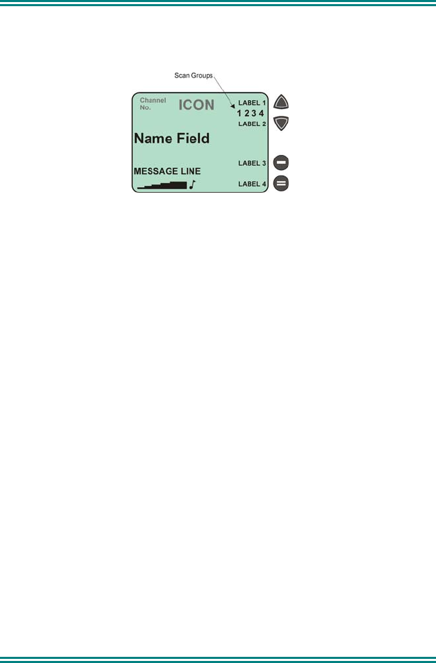
4.1 CHANNELS SCREEN
The Channels Screen shows the current channel and allows it to be changed.
The RSSI Bars indicate the
signal strength of the current
channel.
Channel Number The Name Field shows the
selected entry from the current
Screen (e.g. from Channel List).
M
Displayed Labels show the
current function of the F1 & F4
buttons. Pressing one of these
buttons will execute the function.
The ICON Line displays
various icons as described
in the table below.
The Message Line provides
additional information in the
current Screen. (e.g. name of
Voting or MultiAx channel when
stopped on a channel)
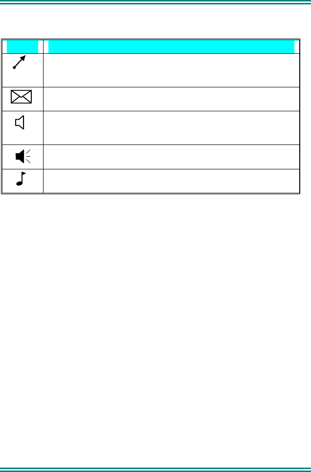
Several Icons can be displayed as shown below:
ICONS INDICATION
A filled speaker icon indicates that a signal is present and the
radio is unmuted.
The outline speaker icon indicates that a signal is present
and the radio is muted. This could be another user group,
for instance.
Received Signal Strength Indication (RSSI). A stronger
signal will display more bars.
Scan Indicator. When radio is on a scan channel and
scanning, the arrow will rotate.
The envelope icon indicates there is one or more stored calls
Transmit indicator
The asterisk symbol indicates whether the radio has been
“called” or is in the “on-call” state.
Keylock
The Keypad may be used to enter numbers directly, which temporarily appear on the
Message-Line (overwriting the Channel Name), e.g. Changing channels from the
keypad can be done by entering the channel number and pressing the ‘#’ button.
Note: If DTMF is enabled then pressing keypad buttons will send the corresponding
DTMF tone.
SRM9022 ~ PMR MOBILE RADIO USER GUIDE
© TMC Radio 2007 page 12 TNM-U-E-0063 Issue 2
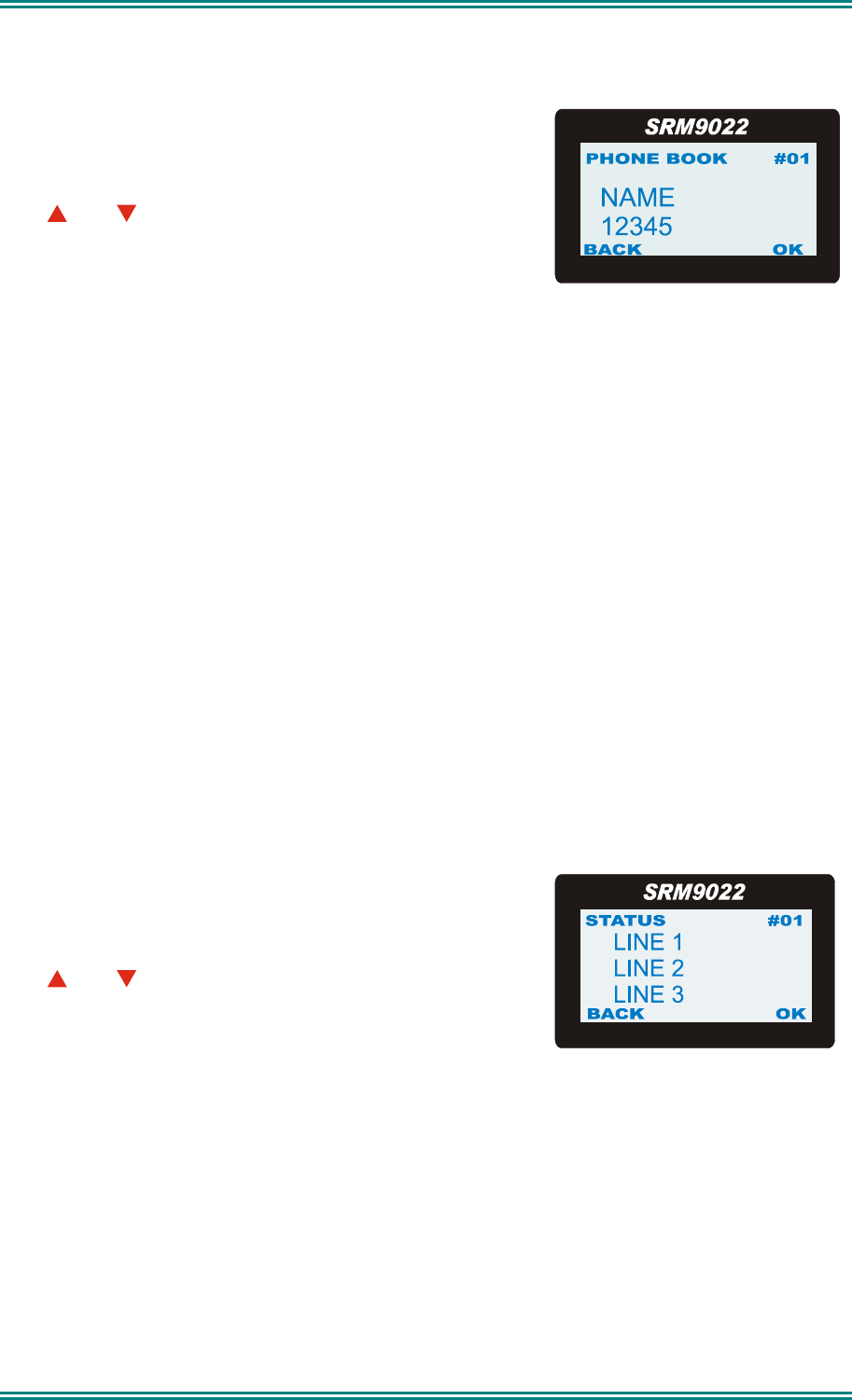
4.2 PHONEBOOK SCREEN
The Phonebook lists the Radio Users and their selcall
codes. Selcall Identity information is stored for
various users and calls can be sent from this Screen.
The and buttons scroll through the Phonebook
entries.
Pressing the OK button will place a call to the displayed identity.
Alternatively, if the Identity Number is known, the Keypad can be used to enter the
number, which is sent when the OK button is pressed.
The F6 button will backspace through keypad entered numbers, or it will exit back to
the Idle Screen if none.
The Back button returns you to the Menu Select Screen.
Refer to section 6.1.6 for details on Phonebook sub-menus.
Notes:: 1. If the Selcall requires a Status to be included then the Saved-Status-Value
will be used. (See description of Status below.)
2 . The Identity shown on the display when this Screen is exited may be
referenced from other Menu Screens and is called the Current-Phonebook-
Entry.
4.3 STATUS SCREEN
The Status Screen is used to send short pre-programmed messages, eg. “at lunch” ,
“job complete” and so on.
This Screen can only be accessed if Selcall is used.
The Selcall Status is selected here and can be sent
from this Screen.
The and buttons scroll through the Status List
entries.
Pressing the OK button will send the displayed Status to the Current-Phonebook-
Entry.
Alternatively, if the Status Number is known, the Keypad can be used to enter the
number, which is sent (to Current-Phonebook-Entry) when the OK button is pressed.
The F6 button will backspace through keypad entered numbers, or it will exit back to
the Idle Screen if none.
The Back button returns you to the Menu Select Screen.
Notes: 1. When a Status is sent, it becomes the current Saved-Status-Value, and can be
used at a later time from other Menu Screens.
SRM9022 ~ PMR MOBILE RADIO USER GUIDE
© TMC Radio 2007 page 13 TNM-U-E-0063 Issue 2
2. The Saved-Status-Value can also be set from the Channel or Phonebook
Screens by entering the number (from the Keypad) and pressing the * button. The
value is saved but not sent.
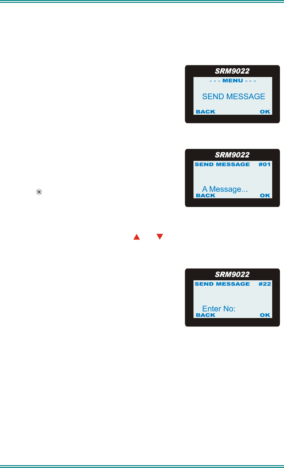
4.4 SEND MESSAGE SCREEN
This Screen allows the user to send a free-form text
message to another radio user in a similar manner to
a cellphone “SMS”.
After selecting the Send Message menu option with
the OK button, a flashing cursor will appear on the
lower LHS of the screen. The line above the flashing
cursor shows the current cursor location.
Each key is labelled with up to 4 text characters. The
text characters are entered by pressing the keypad -
once for the first character, twice for the second, and
three times for the third, and so on.
Note: The key can be used to display up to 28
characters.
After a short delay, the cursor will advance to the
next character entry.
To move the cursor left or right, use the and
buttons.
To delete a character, move the cursor over the
character, then press the F6 function.
A total of 237 characters may be entered.
When the message is complete, press the OK button to send it. The screen will then
ask for the address to send it to with “Enter No.”. Enter the data address and then
press OK. The message will be sent.
After the message is sent, the display will indicate whether the message delivery was
successful.
SRM9022 ~ PMR MOBILE RADIO USER GUIDE
© TMC Radio 2007 page 14 TNM-U-E-0063 Issue 2
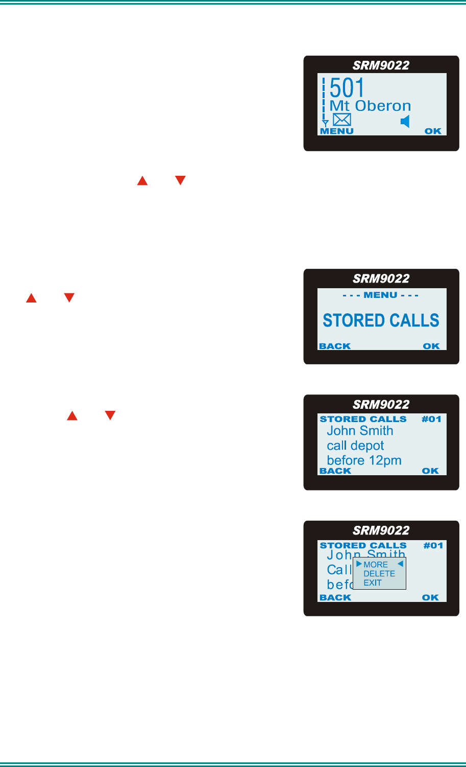
4.5 STORED CALLS SCREEN (SELCALL)
This Screen allows the ten most recent missed
Selcalls (ones not answered before the alert-tone
stops) and received Status Selcalls to be reviewed.
The
icon will show in the Main Channel Screen
when there is an entry in this Screen. A "Bip" tone is
emitted every few seconds when a new call is stored
here.
Press the M key and the and buttons to access the Stored Calls Screen. The
most recent call is shown whenever this Screen is accessed.
The displayed text identifies the caller (e.g. John Smith) and, if used, Status text
(e.g. Call Depot) is displayed on the Message Line.
Press the Back button to return to the Menu Select Screen without making a call.
The and buttons scroll through any other Stored
Calls. The number displayed in the top RHS side of
the screen (eg #05) shows the queued position of the
entry.
For other functions, press OK for the options pop-up
menu. The and buttons allow selection within
the pop-up box.
To view more of a long message that does not fit on
the screen, select More in the pop-up window.
To delete the currently displayed message, select
Delete in the pop-up window.
To exit and return to the channel screen, select Exit
in the pop-up window
SRM9022 ~ PMR MOBILE RADIO USER GUIDE
© TMC Radio 2007 page 15 TNM-U-E-0063 Issue 2
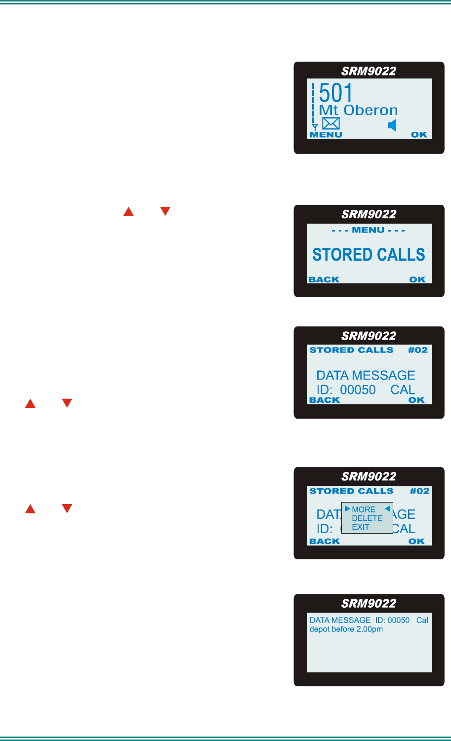
4.6 STORED CALLS SCREEN (DATA MESSAGES)
Received data messages are stored in the Stored
Calls screen. Data messages may be up to 237
characters in length.
The
icon will show in the Main Channel Screen
when there is an entry in this Screen. A "Bip" tone is
emitted every few seconds when a new call is stored
here.
Use the M key and the and buttons to select the
Stored Calls screen. The most recent call is shown
whenever the Stored Calls Screen is accessed.
(Note that data messages may also be displayed
immediately when received, if configured to do so by
the FPP.)
The displayed text identifies the caller (e.g. 02) by
their data address. For example “ID: 00050”.
If the caller is the despatcher as identified by the
FPP, the callers identity is not shown.
The and buttons scroll through any other Stored
Calls, with the displayed number (#05) shows the
queued position of the entry.
To access message options, press OK and a pop-up
selector box will appear.
The and buttons allow selection within the pop-
up box.
To view a long message that does not fit on the
screen, select More in the pop-up window.
To delete the currently displayed message, select
Delete in the pop-up window.
To exit and return to the channel screen, select Exit
in the pop-up window
SRM9022 ~ PMR MOBILE RADIO USER GUIDE
© TMC Radio 2007 page 16 TNM-U-E-0063 Issue 2
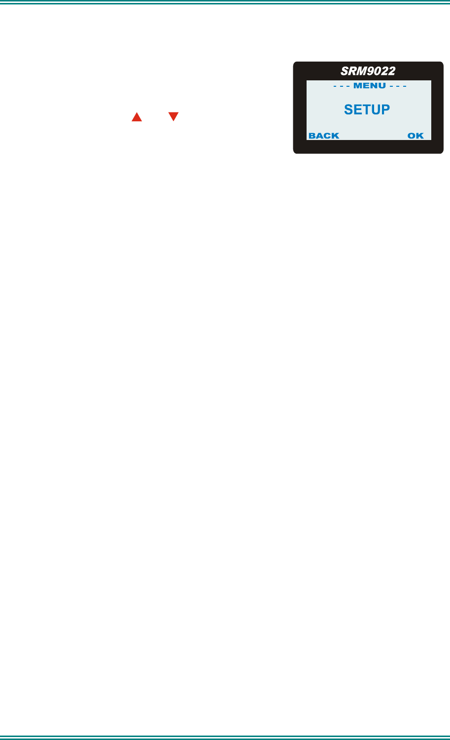
4.7 SETUP SCREEN
Use this Screen to access the other Setup
submenus.
Press the OK button to show the first of the
submenus, and then the and buttons to scroll
through these screens.
Refer to section 6 for details on Setup sub-menus.
SRM9022 ~ PMR MOBILE RADIO USER GUIDE
© TMC Radio 2007 page 17 TNM-U-E-0063 Issue 2
5. COMMON FUNCTIONS AND FACILITIES
5.1 SWITCH-ON/SWITCH-OFF
Momentarily press the red On/Off button to switch
the radio ON.
The display will illuminate and show a ‘Welcome
Message’ and the Selcall Identity of the radio.
After a brief time the display will revert to the Idle
Screen, at which time the radio is ready for use.
Pressing and holding the On/Off button for approximately 2 seconds will switch the
radio Off.
If the radio Inactivity Timer is enabled, the radio will automatically turn Off after
several hours of inactivity (i.e. no buttons pressed).
The radio will emit warning beeps for 10 seconds prior to switching off. Pressing any
button will reset this timer.
The radio can also be setup to switch on automatically with the Vehicle Ignition
whenever the vehicle is started.
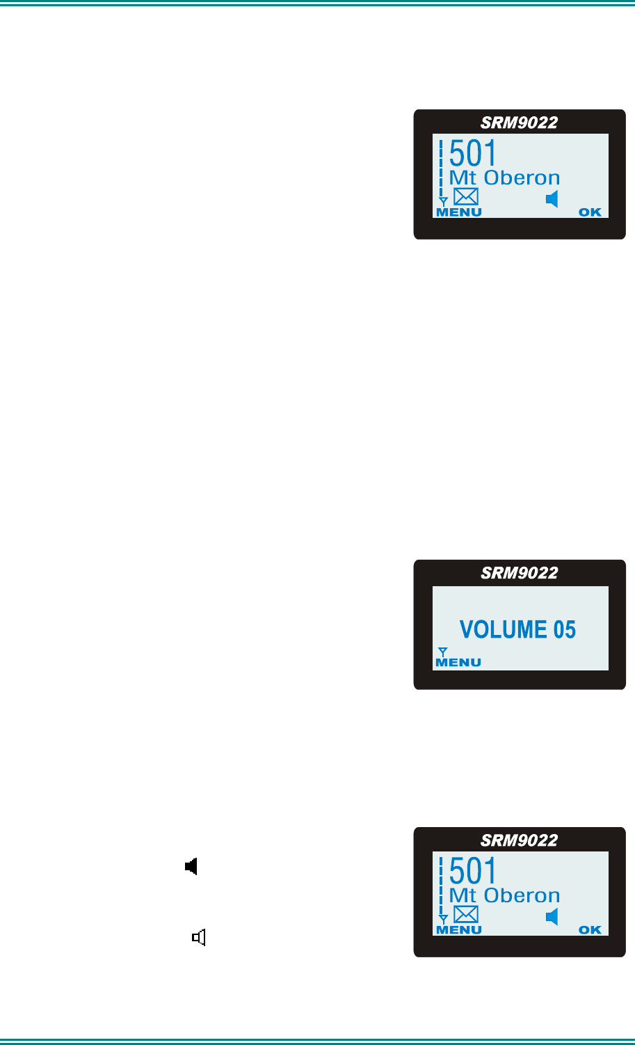
5.1.1 Volume Adjustment
The top +/- buttons adjust the speech level at the
loudspeaker.
Whenever the volume level is adjusted, the screen
briefly shows the current volume setting.
Note: The radio may be programmed so that the volume cannot be turned off
completely.
5.2 RECEIVING
The radio will listen on the displayed Channel.
The Solid Speaker Icon
will show when a valid
signal is being received and audio will be heard at the
Loudspeaker.
An Outline Speaker Icon
will show if a signal is
present but the audio is muted for some reason (e.g.
incorrect CTCSS tone, or the Selcall Mute is closed).

SRM9022 ~ PMR MOBILE RADIO USER GUIDE
© TMC Radio 2007 page 18 TNM-U-E-0063 Issue 2
Changing channels may be achieved by any of the following:
Pressing the and buttons.
Entering the desired channel number from the Keypad and pressing # (e.g. 12#).
Pressing a Go-to-Channel Function Button. (refer to Section 7.11)
Note: If the displayed channel is a Vote or MultiAx channel then the Rotating Arrow
symbol will be displayed while the radio is searching for a signal. When stopped on
a channel the Rotating Arrow disappears and the selected Channel Name may be
displayed.
5.3 TRANSMITTING
To avoid interfering with other users of the channel, listen first to ensure no
transmissions are occurring. Make sure that the Outline Speaker Icon
is not
shown.
Hold the microphone a few centimeters from the mouth, press the “Press to talk”
(PTT) switch and note that the Tx-LED is RED. Speak clearly across the face of the
microphone in a normal conversational manner.
In most systems it is important to wait a short time between pressing PTT and
commencing to speak. This ensures that the path is properly established and avoids
lost or distorted speech.
Use the correct operating procedure and keep transmissions short.
Release the PTT switch as soon as the message is finished.
Notes: 1. A channel may be programmed as “Receive-only” or “Transmit Inhibit” may be
programmed which disallows PTT while the radio is receiving a signal. A
continuous tone will be heard if PTT is disallowed.
2. A Transmit Limit Timer may be setup that limits a continuous transmission on a
channel. The last 10 seconds before the timer expires may be accompanied by
warning tones.
3. The radio may be programmed to send a Selcall (ANI) when the PTT is pressed
or released. This may introduce a short delay before the microphone is enabled or
after PTT is released.
SRM9022 ~ PMR MOBILE RADIO USER GUIDE
© TMC Radio 2007 page 19 TNM-U-E-0063 Issue 2
5.4 SELCALL FUNCTIONS
Selcall is a PMR signalling option that allows the mobile radio to initiate or respond to
an identifying number. Selcall is generally used to allow individual mobiles (or
groups of mobiles) in that system to be to be selectively called.
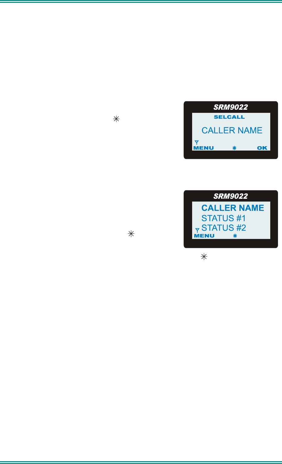
5.4.1 Receiving a Selcall
A number of different options can be set up by the FPP to sound various alert tones
when a selcall is received. Consult your dealer for a detailed explanation of your
radios set up.
When a Selcall is received the radio may respond by:
• Showing a flashing or solid icon to indicate
that the radio has been Called or is On-call, or
• sounding an Alert tone, or displaying the Name
of the caller (if it exists in the Phonebook) or the
numerical identity of the caller (if unknown) on
the display.
This is the alternative Selcall receive Idle Screen,
showing the received Selcall and received Status
information.
Pressing PTT and/or removing the Microphone from
its Cradle may change the state of the icon, stop
the Alert tone and enable the speaker audio.
Replacing the Microphone back into its Cradle may clear the icon (and/or mute
the speaker).
5.4.2 Sending a Selcall
Selcalls are generally sent by accessing the Phonebook Screen (page 12) or the
Status Screen (page 12) for methods of sending a Selcall.
5.4.3 Other Selcall Functions
The SRM9022 has several other functions that affect how the radio operates with
received signals or selcalls. These are described later in this booklet under the
headings:
Monitor/Reset (refer to Section 7.1)
Reset (refer to Section 7.3)
Transpond Enable (refer to Section 7.7)
Send-1, Send-2 (refer to Section 7.6)
Special Encode1...8 (refer to Section 7.12)
SRM9022 ~ PMR MOBILE RADIO USER GUIDE
© TMC Radio 2007 page 20 TNM-U-E-0063 Issue 2
5.5 SCAN FUNCTIONS
Scanning consists of sequentially searching up to 15 channels for a valid signal (RF,
CTCSS or DCS tone). When found the radio will stop on that channel until the signal
disappears again.
The Microphone may need to be in the cradle, (on hook) for the radio to scan.
While listening on the channel, the User may PTT on that channel. After the signal
disappears the radio will remain listening on the channel for a short time (typically 3
seconds) before resuming scanning. PTT is inhibited while the Mic is in cradle.
If a Priority/Emergency Channel is assigned, the radio will interleave a check of this
channel between each normal channel check. The radio may also check the Priority
Channel every few seconds while stopped on a channel. If a signal is found on the
Priority Channel then the radio will switch to that channel immediately.
If programmed, the Priority Channel is automatically selected when the Microphone
is removed from cradle.
To activate Scanning, press the SCAN Function button from the Main Channel
Screen.
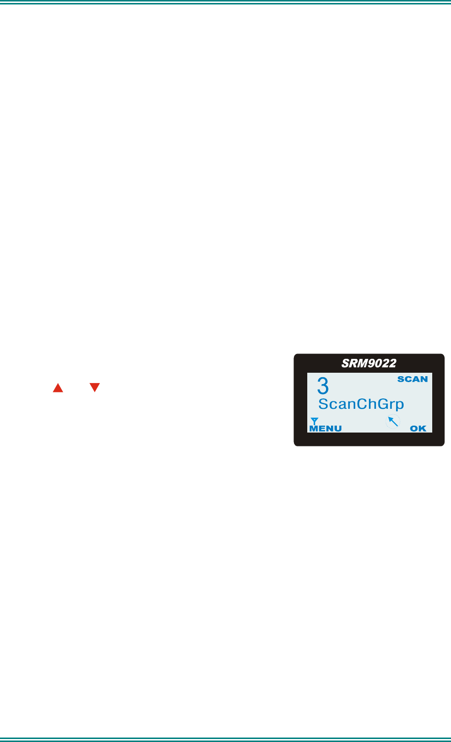
5.5.1 Scan Screen
The display shows the name of the current Scan-
Group (e.g. “ScanChGrp”), which may be changed
using the and buttons.
The Scan-Group Number is shown at the top-left of
the display, i.e. 1…4 if it is a User Scan-Group, or
blank for Fixed Scan-Groups. While the Scan Screen
is displayed the radio is scanning the shown group.
The Scan Screen does not time-out. Normal exit is via the OK button.
The RSSI indicator shows the received signal strength as the radio is scanning.
All other buttons have the same assignments as in the Main Channel Screen.
When stopped on a channel, the name of the selected site, and the “rotating arrow”
symbol is replaced by the Speaker symbol.
To temporarily skip the channel from the Scan-Group, press OK then select “Skip”.
Skipped channels are restored when a different Scan Group is selected or if Scan is
exited. The Priority Channel cannot be skipped.
OK: Edit is only active for User Scan Groups and opens up the Scan-Edit Screen for
the selected Scan-Group allowing Channels to be added, deleted or set as the
priority channel (see below).
SRM9022 ~ PMR MOBILE RADIO USER GUIDE
© TMC Radio 2007 page 21 TNM-U-E-0063 Issue 2
While listening on the channel, the User can PTT on that channel. After the signal
disappears (or Microphone is placed back in Cradle) the radio will remain listening on
the channel for a short time before resuming scanning.
The Microphone may need to be in cradle for the radio to scan. If the Microphone is
left off-cradle for too long then the radio may sound a continuous alert tone until it is
replaced.
DTMF (if enabled) is only active when the Mic is out of cradle.
The Keypad may NOT be used for quick channel change (e.g. 456#) in this Screen.
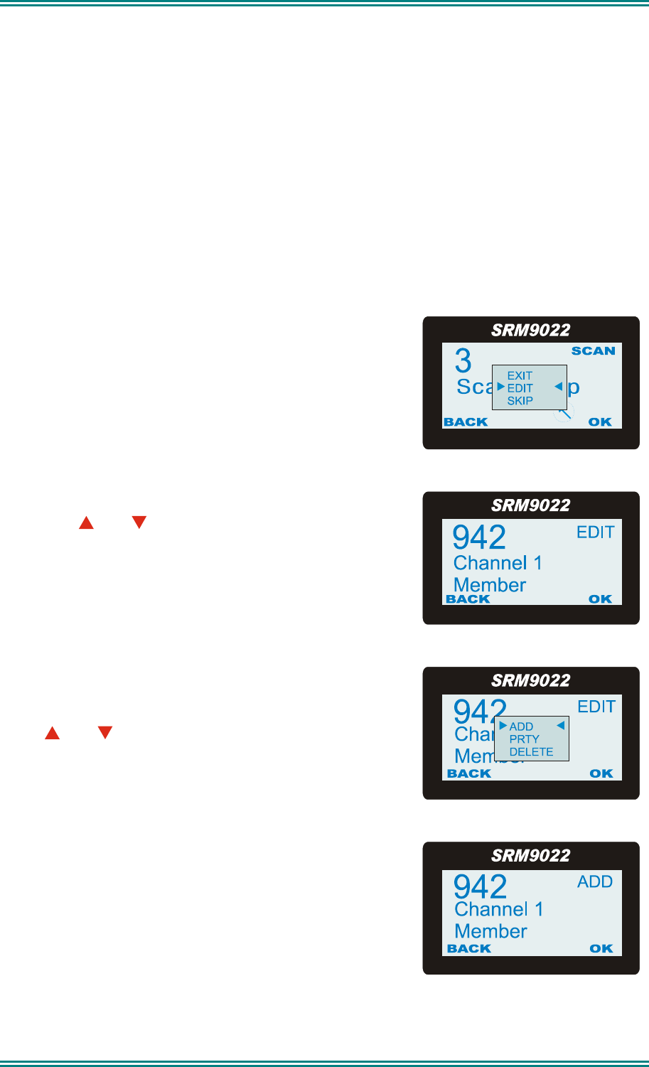
5.5.2 Scan-Edit Screen
Press OK and select Scan Edit.
In the Scan-Edit Screen the display shows the
Channel List (excluding Vote and MultiAx channels)
and the Message-Line shows either “Member” or
“Priority”.
Press the and buttons to show channels within
the Scan Group.
Press OK to Add/Delete a channel, or Change the
Priority Channel.
If the and buttons were used to select ADD……
….then this Screen will appear. Press OK to confirm
channel selection and to return to the previous
screen.

SRM9022 ~ PMR MOBILE RADIO USER GUIDE
© TMC Radio 2007 page 22 TNM-U-E-0063 Issue 2
Alternatively, if the and buttons were used to
select PRIORITY…….
….then this Screen would appear. Press OK to
confirm Priority selection and to return to the previous
screen.
When adding Channels (or changing Priority Channel), press and buttons to
scroll through all available channels, and press OK to make a selection.
Note: “Member” and “Priority” text strings will only be displayed if the channel is a
member of the group.
In all Screens, press Back to return to previous Screen.
5.6 DTMF OPERATION
When DTMF is enabled, DTMF tones can be sent using the Keypad from the Main
Channel Screen. Pressing 0...9, * and # will send the associated tones.
The tone period and gap are set by the programmer.
DTMF can be enabled in several ways:
via the DTMF option in the User-Options sub-menu under the SETUP Menu (refer to
Section 6).
If the DTMF Function is assigned to a F1...6 button, DTMF is enabled when the
button indicator is ON.
5.7 EXTERNAL ALERT
Provision is made to connect an external alerting device to the rear of the radio. The
external alert may be activated when a selcall is received (and cancelled by a
timeout, user intervention or receiving a different selcall).
This function is enabled by software programming. When enabled, the External Alert
feature may be switched On or Off using a Function button.
5.8 AUXILIARY OUTPUT
Provision is made for connection to an Auxiliary Output on the rear of the radio. This
output is enabled by software programming and can be used to activate an external
device. When enabled, the function is toggled On/Off using a Function button.
SRM9022 ~ PMR MOBILE RADIO USER GUIDE
© TMC Radio 2007 page 23 TNM-U-E-0063 Issue 2
6. SETUP
The Setup sub-menus allow the operator to edit/modify the operation of some of the
general functions of the radio. The programmer can restructure or restrict access to
any or all of these menus and may restructure them according to specific
requirements.
6.1 SETUP SUB-MENUS
The Setup sub-menu structure programmed at manufacture is shown in Figure 2.
These sub-menu Screens provide access to operator functions as follows.
User Options Key beeps, Backlight, Dual Watch & DTMF on/off selection.
Mute Adjust Mute Level adjustment .
Phone Book Edit Allows Phonebook entries to be changed, deleted or added.
Contrast Displays contrast adjustment.
Alert Volume Alert “beep” tone level setting (relative to Audio Volume).
Radio Information FPP File description, SW version, Serial No. Selcall ID.
Mode Selects Trunk (Network 1/2), PMR, or P25 operation mode.
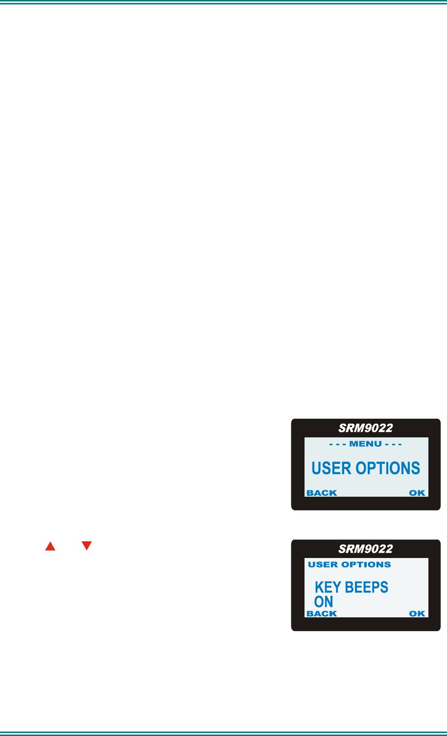
6.1.1 User Options
The User Options Screen allows a variety of user
options (such as Keybeeps, Backlight, Dual Watch
and DTMF facilities) to be set On or Off.
The option selections are set with the FPP.
Use the and buttons to scroll between the
different options.
The OK button toggles the selection On/Off.
The setting is saved immediately.
SRM9022 ~ PMR MOBILE RADIO USER GUIDE
© TMC Radio 2007 page 24 TNM-U-E-0063 Issue 2
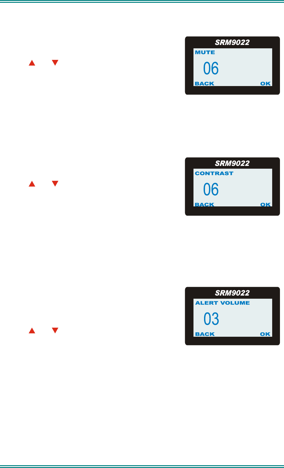
6.1.2 Mute Adjust
Select the Mute Adjust Screen to change current
Mute setting.
Use the and buttons to change the Mute level.
Press the OK or Back button to save new Mute
setting.
Note : When a Voting channel is selected the Voting-Mute level is shown, but may not be
changed.
6.1.3 Contrast
The Contrast Screen allows you to set the contrast
level of the Display in the range from 0 to 15.
Use the and buttons to select the required
contrast setting.
Press OK to accept the setting and return to the Idle
Screen.
Press Back to accept the setting and return to the Menu Select Screen.
6.1.4 Alert Volume
This Screen allows you to set the level of the Alert
Volume Beep Tone in relation to the current Volume
setting. The level can be set in 63 steps over the
range -31 to +31.
Use the and buttons to change the relative alert
level
Press OK to accept the setting and return to the Idle Screen.
Press Back to accept the setting and return to the Menu Select Screen.
Note: A minimum Alert Level may be set to ensure the Alerts can always be heard from
the speaker.
SRM9022 ~ PMR MOBILE RADIO USER GUIDE
© TMC Radio 2007 page 25 TNM-U-E-0063 Issue 2
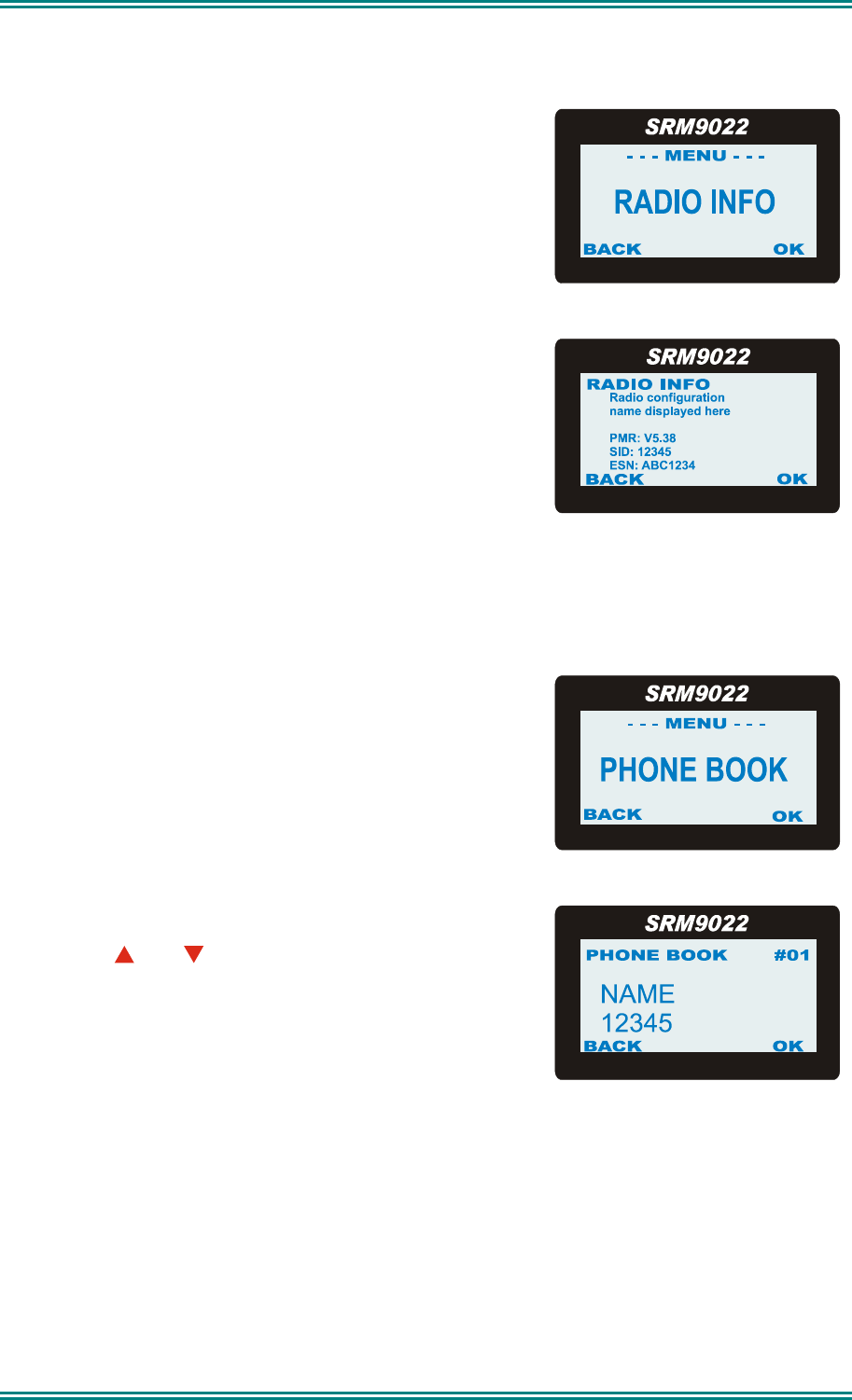
6.1.5 Radio Information
This Screen displays information that identifies the…
• Programmer File description
• Software Version
• Selcall ID, and …
• Radio Serial Number and ESN.
Press OK to return to the Idle Screen.
Press Back to return to the Menu Select Screen.
6.1.6 Phone Book Menu
From the Main Menu, press OK to select the
Phonebook Screen.
Once in the Phonebook Screen….
• The and buttons to scroll through the
Entries…
• Pressing OK will select an Entry.
• Press the Back button will return you to the
previous screen.
Note: Use F6 button when you need to backspace.
SRM9022 ~ PMR MOBILE RADIO USER GUIDE
© TMC Radio 2007 page 26 TNM-U-E-0063 Issue 2
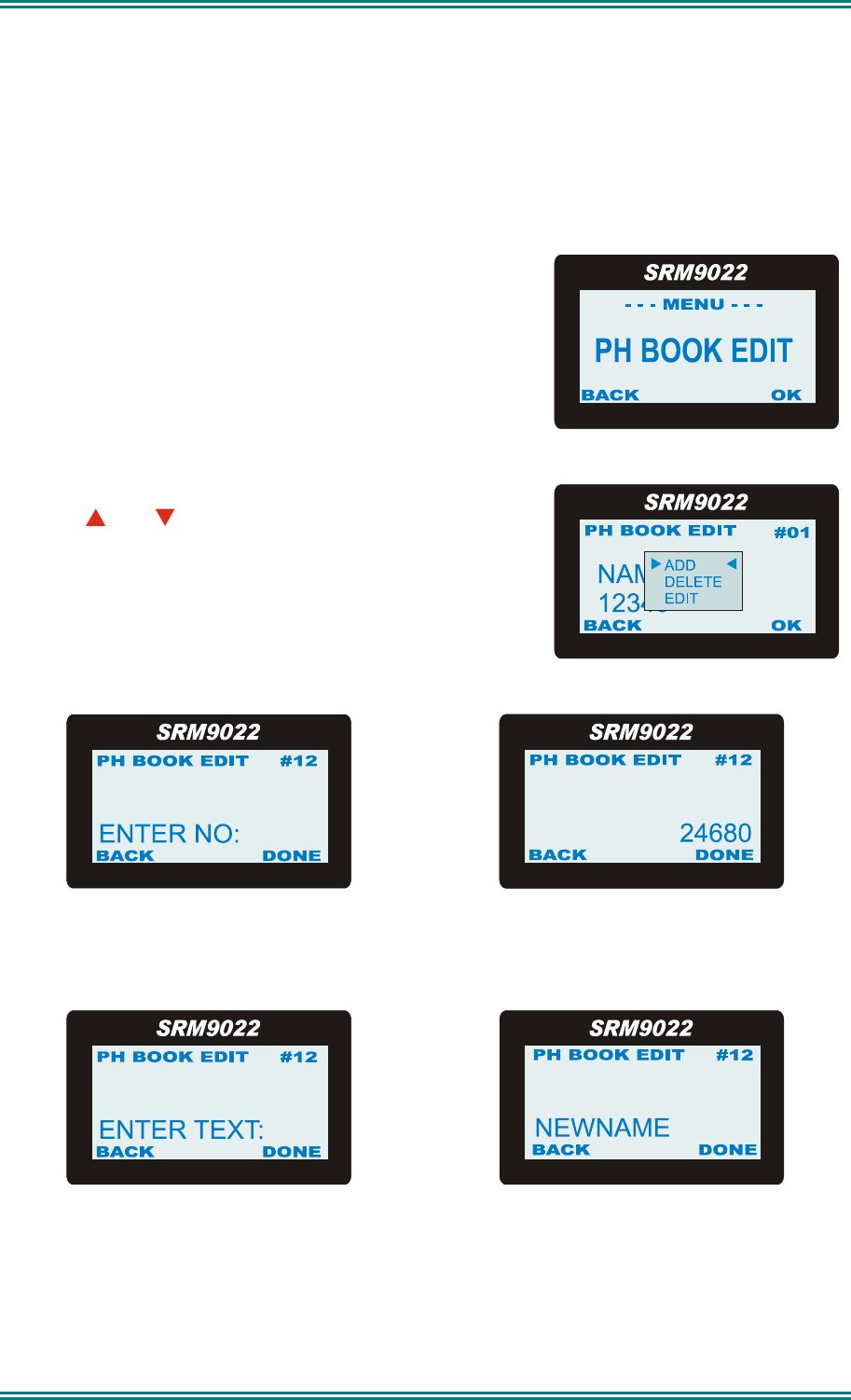
6.1.7 Phone Book Edit Menu
The Phone book Edit Screen allows you to Add, Delete or Edit phone book entries.
6.1.7.1 ADD A NEW ENTRY
From the main Phone Book Edit Screen (at any
Phonebook Entry), just press OK.
Use the and buttons to select “Add” and press
OK.
Enter the new Entry number using the
keypad.
…..and press OK.
Next, enter new Entry text using the ABC
keypad (see 6.1.7.4 below),
…..and press OK again to exit back to
the Idle Screen.
SRM9022 ~ PMR MOBILE RADIO USER GUIDE
© TMC Radio 2007 page 27 TNM-U-E-0063 Issue 2
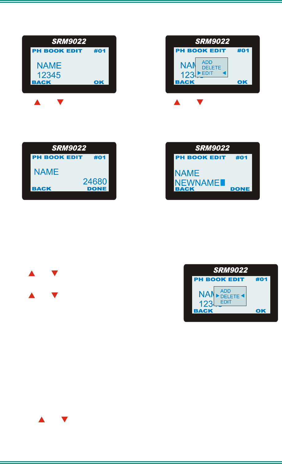
6.1.7.2 EDIT AN EXISTING ENTRY
Use the and buttons to select the
required Phonebook Entry, then Press
OK.
Use the and buttons to select “Edit”
and then press OK..
Next, edit the number using the F6 key
and keypad and press OK.
Edit text using the ABC keypad (see
6.1.7.4 below) and press OK to exit back
to the Idle Screen
6.1.7.3 DELETE AN ENTRY
Use the and buttons to select the required
Phonebook Entry, then press OK.
Use the and buttons to select “Delete”, then
press OK to delete the Entry and exit back to the Idle
Screen.
6.1.7.4 USING THE KEYPAD FOR TEXT
When using the keypad to type text:
• press the appropriate keypad button a number of times until the desired character
or number is selected,
• the current character position is identified by a flashing block cursor,
• use ‘#’ to select lower/upper case letters,
• use the and buttons to move to the next or previous character space to be
entered/modified, and…
• press OK to accept changes.

SRM9022 ~ PMR MOBILE RADIO USER GUIDE
© TMC Radio 2007 page 28 TNM-U-E-0063 Issue 2
6.1.8 Mode Selection
The Mode Screen allows you to switch operation
between;
• Trunk Network 1
• Trunk Network 2
• PMR mode, or …
• P25 mode.
Use the and buttons to make your selection, and
press OK to accept.
Press Back to return to the Menu Select Screen
without changing modes.
PMR
MODE
BACK OK
SRM902
2
Note: Refer to the relevant Operating Instructions for Trunk or P25 operation.

SRM9022 ~ PMR MOBILE RADIO USER GUIDE
© TMC Radio 2007 page 29 TNM-U-E-0063 Issue 2
7. SPECIAL FUNCTION BUTTONS
This section lists Functions that may be programmed to the F1, F2, F3, F4, F5 or F6
buttons.
Consult your TMC Radio Dealer for which functions have been programmed in to
your radio.
7.1 MONITOR
Opens/Closes the audio (signalling) mute.
Only valid on Non-Community Repeater type channels and/or Closed Selcall
channels without Receiver Lock-out programmed.
7.2 SQUELCH DEFEAT
Opens/Closes the squelch (carrier) mute.
7.3 RESET
Closes the audio (signalling) mute on closed Selcall Channels.
7.4 SCAN
Activates Scanning, refer to Section 5.5.
7.5 AUXILIARY
Toggles the external output, refer to Section 5.8.
7.6 SEND-2
Sends a specific selcall sequence.
7.7 TRANSPOND
Enables/Disables Individual Call Acknowledge.
7.8 CTCSS
Defeats the CTCSS mute on the channel
Only valid on Non-Community Repeater type channels and/or Open Selcall channels.
7.9 MUTE
Provides direct access to the Mute Setup screen (refer to Section 6.1.2) and allows
the user to change the mute level from that screen.
7.10 EXTERNAL ALERT
Enables/Disables control of External Output via Selcall Decodes, refer to Section 5.4.
7.11 GOTO CHAN A, B, C, D
Selects predefined Channel A, B, C or D, and (may) return on the second press.
The Defined Channel may be redefined if held for approximately 2 seconds.
7.12 SPECIAL ENC 1…8
Sends Special Encode 1, 2, … 8
7.13 ALARM
Put the mobile into Alarm mode.
7.14 REPEATER DEFEAT
Allows the radio to transmit on the reverse frequency on a Repeater Channel.
When the button is pressed again (or the Channel is changed) the transmit frequency
reverts to the original setting.

SRM9022 ~ PMR MOBILE RADIO USER GUIDE
© TMC Radio 2007 page 30 TNM-U-E-0063 Issue 2
7.15 LOW POWER
Forces the radio to low power.
Pressing again puts the radio back to the power level defined for the current channel.
This is not affected by Channel changes.
7.16 DTMF MODE
This function places the numeric keypad into DTMF mode. refer to Section 5.6.
7.17 SCRAMBLER ON/OFF
This function toggles the operation of the frequency inversion voice scrambler.
7.18 SEND DTMF1/2
This function sends a pre-programmed string of up to 16 DTMF digits.
7.19 LOCK / UNLOCK KEY
This function unlocks the keypad by holding down the programmed function buttons
for 2 seconds.

SRM9022 ~ PMR MOBILE RADIO USER GUIDE
© TMC Radio 2007 page 31 TNM-U-E-0063 Issue 2
8. OPTIONS
The following options are available, contact your dealer for further information.
8.1 QUICK RELEASE TRANSCEIVER KIT (MA-QRCRADLE)
This kit provides a mounting cradle to allow the Transceiver to be quickly removed
without having to undo unnecessary screws.
8.2 MICROPHONE/CONTROL HEAD EXTENSION LEAD
This lead allows the Transceiver to be placed up to 4.5 metres from the Control
Head.
8.3 TYPE 1 PARALLEL I/O EXPANSION OPTION
This option provides eight I/O lines and pre/de-emphasised audio to allow external
interfacing to the radio.
8.4 INTERNAL GPS OPTION
This provides Global Position reporting for Trunk and PMR applications.
8.5 CROSS-LINKED CABLE
This is used with various applications to cross-connect or interconnect Transceivers
or Control Heads.
8.6 600 OHM INTERFACE OPTION
This provides a balanced 600 Ohm 2/4 wires audio interface and opto-isolated E and
M lines.
8.7 TYPE 2 I/O OPTION
This interface board is designed for multiple Transceivers or Control Heads.
8.8 DUAL CONTROL HEAD OPTION
This allows two Control Heads to be used from one Transceiver.
8.9 DUAL TRANSCEIVER OPTION
This allows two transceivers to be used with one Control Head.
8.10 DESK TOP BASE KIT
This provides a housing for the radio and incorporates an 8 Amp Power Supply Unit
and speaker.

SRM9022 ~ PMR MOBILE RADIO USER GUIDE
© TMC Radio 2007 page 32 TNM-U-E-0063 Issue 2
9. TROUBLESHOOTING
If, after reading this guide, you are unable to switch the radio on, check the following:
• A fuse has not blown.
Your installer should advise you of the location of the two main fuses,
• The power supply cables and their connections are secure, and
• The vehicle battery is charged.
• If these checks are OK, contact your dealer or TMC Radio representative for
further advice.

SRM9022 ~ PMR MOBILE RADIO USER GUIDE
© TMC Radio 2007 page 33 TNM-U-E-0063 Issue 2
SRM9022 ~ PMR MOBILE RADIO USER GUIDE
© TMC Radio 2007 page 34 TNM-U-E-0063 Issue 2
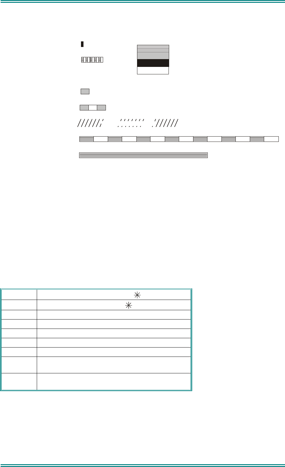
10. APPENDIX A - ALERT TONES AND MESSAGES
Key Beep
Error Tone
Beep Alert
Bip Alert
Ring Alert
Urgent Alert
Continuous Alert
2 x Bip Alert
0.0
5
9000_52
0.10
0.05
0.10
0.10
Continuous
Telephone Ring Tone
0.19
Duration Indicated in seconds
880 Hz
Off
1480 Hz
440 Hz
Figure 2 – Alert Tones
These messages are displayed on the Message Line to give the user additional
information.
Called Indicates Selcall state (for flashing icon).
On Call Indicates Selcall state (for solid icon).
Queued A Selcall is queued waiting to be sent.
Voting Additional information about the Channel type.
MultiAx Additional information about the Channel type.
Scanning Additional information about the Channel type.
Dual Watch Dual Watch function is enabled.
Member Scan Edit: Indicates that the displayed channel is a
member of the current Scan Group.
Priority Scan Edit: Indicates that the displayed channel is the
Priority Channel in the current Scan Group.

SRM9022 ~ PMR MOBILE RADIO USER GUIDE
© TMC Radio 2007 page 35 TNM-U-E-0063 Issue 2
11. APPENDIX B - GLOSSARY
A summary of common radio terms and some other terms used in this document, and
their meanings, are given below.
Alert tones The transceiver emits these tones to indicate an invalid
operator or error.
Cradle The bracket that holds the microphone when it is not in use
(on hook).
Current Phonebook
Entry
Name that would be shown were the Phonebook screen
shown.
DSP
Digital Signal Processor.
DTMF Dual Tone Multi-Frequency (Signaling Method).
LCD Liquid crystal display.
MIC Abbreviation for microphone.
MPT1327 Refers to the UK Ministry for Post and Telecommunications
specification defining the low level protocol for public
trunking systems.
MPT1343 Refers to the UK Ministry for Post and Telecommunications
specification defining the User Interface for radios operating
on MPT1327 public trunking systems.
Network The system infrastructure, eg a Trunked Network.
PMR Private Mobile Radio
PTT Press-to-Talk. Hold down the Press-to-talk switch on the
microphone for the duration of the transmission.
RF Radio Frequency.
RSSI Received Signal Strength Indicator
Selcall Selective Call. A signalling system that identifies users.
Saved Status
Value
The last Status that was sent, entered or optionally
received.
TMR Trunked Mobile Radio

SRM9022 ~ PMR MOBILE RADIO USER GUIDE
© TMC Radio 2007 page 36 TNM-U-E-0063 Issue 2
12. APPENDIX C – COMPLIANCE WITH RF ENERGY EXPOSURE
GUIDELINES (UNITED STATES AND CANADA)
RF ENERGY EXPOSURE AWARENESS AND CONTROL INFORMATION AND OPERATIONAL
INSTRUCTIONS FOR FCC OCCUPATIONAL USE REQUIREMENTS.
Before using your TMC Radio mobile two-way radio, read this important RF energy awareness and
control information and operational instructions to ensure compliance with the FCC’s RF exposure
guidelines.
NOTICE: This radio is intended for use in Occupational/ controlled conditions in a mobile
application where users have full knowledge of their exposure and can exercise control over
their exposure to meet FCC limits. This radio device is NOT authorised for general population,
consumer, or any other use.
This two-way radio uses electromagnetic energy in the radio frequency (RF) spectrum to provide communications between
two or more users over a distance. It uses radio frequency (RF) energy or radio waves to send and receive calls. RF energy is
one form of electromagnetic energy. Other forms include, but are not limited to, electric power, sunlight and x-rays. RF
energy, however, should not be confused with these other forms of electromagnetic energy, which when used improperly can
cause biological damage. Very high levels of x-rays, for example, can damage tissues and genetic material.
Experts in science, engineering, medicine, health and industry work with organizations to develop standards for exposure to
RF energy. These standards provide recommended levels of RF exposure forboth workers and the general public. These
recommended RF exposure levels include substantial margins of protection. All two-way radios marketed is North America
are designed, manufactured and tested to ensure they meet government established RF exposure levels. In addition,
manufacturers also recommend specific operating instructions to users of two-way radios. These instructions are important
because they inform users about RF energy exposure and provide simple procedures on how to control it. Please refer to the
following websites for more information on what RF energy exposure is and how to control your exposure to assure
compliance with established RF exposure limits.
http:l/www.fcc. gov/oet/rfsafety/rf-fags. htm 1
http://www.osha.gov/SLTC/radiofrequencvradiation/index.htmi
Federal Communications Commission Regulations:
The FCC rules require manufacturers to comply with the FCC RF energy exposure limits for mobile
two-way radios before they can be marketed in the U.S. When two-way radios are used as a
consequence of employment, the FCC requires users to be fully aware of and able to control their
exposure to meet occupational requirements. An exposure awareness label is attached to the
equipment directing users to specific awareness information.
Compliance with RF Exposure Standards
Your TMC two-way radio is designed to comply with a number of national and international standards
and guidelines (listed below) regarding human exposure to radio frequency electromagnetic energy.
This radio complies with the IEEE (FCC) and ICNIRP exposure limits for Occupational/ Controlled RF
exposure environment at duty factors of up to 50% talk 50% listen and is authorised by the FCC for
occupational use. In terms of measuring RF energy for compliance with the FCC exposure guidelines,
your radio radiates measurable RF energy only while it is transmitting (during talking), not when it is
receiving (listening) or in standby mode.
Your TMC Radio two-way radio complies with the following RF energy exposure standards and
guidelines:
• United States Federal Communications Commission, Code of Federal Regulations; 47CFR
part 2 sub-part J
• American National Standards Institute (ANSI) / Institute of Electrical and Electronic Engineers
(IEEE) C95. 1-1992
• Institute of Electrical and Electronic Engineers (IEEE) C95.1-1999 Edition

SRM9022 ~ PMR MOBILE RADIO USER GUIDE
© TMC Radio 2007 page 37 TNM-U-E-0063 Issue 2
RF Exposure Compliance and Control Guidelines and
Operating Instructions
To control exposure to yourself and others and ensure compliance with the Occupational/ Controlled
environment exposure limits always adhere to the following procedures.
Guidelines:
• User awareness instructions should accompany the device when transferred to other users.
• Do not use this device if the operational requirements described herein are not met.
Instructions:
• Transmit no more than the rated duty factor of 50% of the time. To transmit (talk), push the
Push-To-Talk button. To receive calls, release the PTT button. Transmitting 50% of the time,
or less, is important because this radio generates measurable RF energy exposure only when
transmitting (in terms of measuring for standards compliance).
• Transmit only when people outside the vehicle are at least the recommended minimum lateral
distance away, as shown in Tables 1 and 2, from a properly installed according to installation
instructions, externally-mounted antenna.
NOTE- Table 1a) lists the recommended minimum lateral distance for bystanders in an uncontrolled
environment from the transmitting antenna for the SRM9000AC (150MHz-174MHz) mobile rated
power (25 watts) installed in a vehicle. Table 1b) lists the recommended minimum lateral distance for
occupational/ controlled use.
Table 2a) lists the recommended minimum lateral distance for bystanders in an uncontrolled
environment from the transmitting antenna for the SRM9000UW (440MHz-512MHz) mobile rated
power (25 watts) installed in a vehicle. Table 2b) lists the recommended minimum lateral distance for
occupational/ controlled use.
SRM9022 ~ PMR MOBILE RADIO USER GUIDE
© TMC Radio 2007 page 38 TNM-U-E-0063 Issue 2
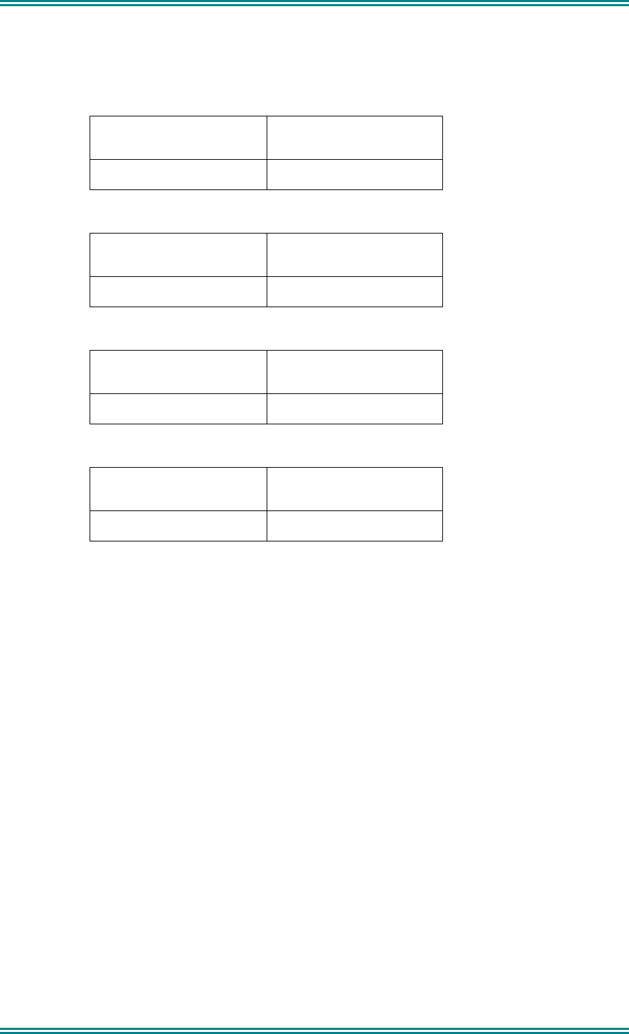
Table 1a). Rated Power and Recommended Lateral Distance for
General Population uncontrolled exposure for SRM9000AC (150MHz to 174MHz).
Rated Power of Vehicle-
installed Mobile Two-way
Radio
Recommended Minimum
Lateral Distance from
Transmitting Antenna
25 watts with λ/4 dipole
(2.14dBi gain) 90cm (35.5 inches)
Table 1b). Rated Power and Recommended Lateral Distance for
Occupational/ Controlled exposure for SRM9000AC (150MHz to 174MHz).
Rated Power of Vehicle-
installed Mobile Two-way
Radio
Recommended Minimum
Lateral Distance from
Transmitting Antenna
25 watts with λ/4 dipole
(2.14dBi gain) 40cm (15.75 inches)
Table 2a). Rated Power and Recommended Lateral Distance for
General Population uncontrolled exposure for SRM9000UW (440MHz to 512MHz).
Rated Power of Vehicle-
installed Mobile Two-way
Radio
Recommended Minimum
Lateral Distance from
Transmitting Antenna
25 watts with λ/4 dipole
(2.14dBi gain) 75cm (29.5 inches)
Table 2b). Rated Power and Recommended Lateral Distance for
Occupational/ Controlled exposure for SRM9000UW (440MHz to 512MHz).
Rated Power of Vehicle-
installed Mobile Two-way
Radio
Recommended Minimum
Lateral Distance from
Transmitting Antenna
25 watts with λ/4 dipole
(2.14dBi gain) 34cm (13.5 inches)
Vehicle Installation Instructions:
The antenna(s) used for the SRM9000series of mobile two-way radios must be installed to provide a
separation distance of at least 75cm from all persons for SRM9000UW (440-512MHz) and 90cm for
SRM9000AC (150-174MHz). The gain of the antenna(s) may not be greater than 0dBd (2.14dBi).
If the required separation distance extends beyond the physical boundary of the vehicle, the antenna
must be installed on the center of the roof ONLY and must be installed in a vehicle having the
following characteristics in order to prevent bystanders from being exposed to levels exceeding the
limits set for General Population/ Uncontrolled exposure environment:
• All passengers must be sitting under a solid metal roof
• The rooftop width must be at least 150cm (59 inches) for SRM9000UW (440-
512MHz), or 180cm (71 inches) for SRM9000AC (150-174MHz).
Mobile Antenna:
• Install the antenna at the center of the roof or the center of the trunk deck, taking into account
the bystander exposure conditions of backseat passengers and recommended minimum
lateral distances in Table 1a) and 2a). These mobile antenna installation guidelines are limited
to metal body motor vehicles or vehicles with appropriate ground planes.
• The antenna installation must additionally be in accordance with:
a.) The requirements of the antenna manufacturer/supplier

SRM9022 ~ PMR MOBILE RADIO USER GUIDE
© TMC Radio 2007 page 39 TNM-U-E-0063 Issue 2
b.) Instructions in the Radio Installation Manual, including minimum antenna cable lengths.
c.) The installation information of how to install the antenna to facilitate recommended
operating distances to all potentially exposed persons.
• Use only TMC Radio approved supplied antenna or TMC Radio approved replacement
antenna. Unauthorized antennas, modifications, or attachments could damage the radio and
may violate FCC regulations.
Approved Accessories
• This radio meets the FCC RF exposure guidelines when used with the TMC Radio
accessories supplied or designated for the product. Use of other accessories may not ensure
compliance with the FCC’s RF exposure guidelines and may violate FCC regulations.
• To obtain a list of TMC Radio approved accessories see contact details below or visit the
following website which lists approved accessories: http://www.tmcradio.com
Contact Information
For additional information on exposure or other information, please contact
TMC Radio Pty. Ltd.
1270 Ferntree Gully Road
Scoresby
Victoria, 3179
Australia
Telephone +61 3 9730 3800
Facsimile +61 3 9730 3968
Email orderdesk@tmcradio.com
Website www.tmcradio.com
SRM9030
Mobile Radio
Conventional – PMR
Operating Instructions
TNM-U-E-0003 Issue 4
March 2007
TMC Radio Pty. Ltd.
1270 Ferntree Gully Road
Scoresby
Victoria, 3179
A
ustralia
www.tmcradio.com

SRM9030 ~ PMR Mobile Radio User Guide
© TMC Radio 2007 i TNM-U-E-0003 Issue 4
ASSOCIATED DOCUMENTATION
The following documentation is available for use with the SRM9000 series of
products:
TNM-I-E-0005 SRM9000 Series Installation Instructions
TNM-M-E-0001 SRM9000 Service Manual
TNM-U-E-0012 SRM9020 Trunked Operating Instructions
TNM-U-E-0013 SRM9020 PMR Operating Instructions
TNM-U-E-0063 SRM9022 PMR Operating Instructions
TNM-U-E-0065 SRM9022 Trunked Operating Instructions
TNM-U-E-0004 SRM9030 Trunked Operating Instructions
To order copies of any of the above publications, or any other TMC Radio
product, contact TMC Radio on +61 3-9730-3800 or send a Fax on +61 3-
9730-3968.
ABOUT THIS DOCUMENT
This publication is copyright and no part may be reproduced without prior
permission of TMC Radio.
Due to our policy of continuous improvement to our products and services,
technical specifications and claims, correct at time of publication, may be
subject to variation without prior notice.
TMC Radio has endeavoured to ensure that the information in this document is
fairly and accurately stated, but does not accept liability for any errors or
omissions.

SRM9030 ~ PMR Mobile Radio User Guide
TNM-U-E-0003 Issue 4 Page ii © TMC Radio 2007
SAFETY
1. Do NOT operate your radio, without a handsfree kit, whilst driving a
vehicle.
2. Do NOT operate your radio in an explosive atmosphere.
Obey the 'Turn Off Two-way Radios' signs where these are posted,
e.g. on a petrol station forecourt.
3. Do NOT touch the antenna while the radio is transmitting.
4. Do NOT operate the radio if the antenna has become disconnected or
damaged.
HINTS FOR USING THE RADIO
• When speaking, hold the microphone a few centimeters from your mouth
and speak across it, rather than into it.
• Keep the length of your conversation to a minimum and replace the
microphone on its cradle after use.
• When it is possible to move location, avoid making calls from known poor
signal-strength areas such as the radio systems fringe areas (limit of
range) or from screened or shadowed areas, e.g. an underground car park
or underpass.
• To avoid unnecessary drain on the vehicle battery, keep the engine
running when using the radio for extensive periods of time.

SRM9030 ~ PMR Mobile Radio User Guide
© TMC Radio 2007 iii TNM-U-E-0003 Issue 4
CONTENTS
ASSOCIATED DOCUMENTATION........................................................... I
ABOUT THIS DOCUMENT ....................................................................... I
SAFETY II
HINTS FOR USING THE RADIO ............................................................. II
CONTENTS............................................................................................. III
1. INTRODUCTION ................................................................................ 1
1.1 Overview......................................................................................1
1.2 Installation...................................................................................1
2. FRONT PANEL CONTROLS ............................................................. 2
3. MENU SYSTEM.................................................................................. 3
3.1 Menu Navigation.........................................................................3
3.2 Default Settings ..........................................................................4
4. MAIN MENU SCREENS ..................................................................... 5
4.1 Channels Screen.........................................................................5
4.2 Phonebook Screen .....................................................................7
4.3 Status Screen..............................................................................8
4.4 Stored Calls Screen (Selcall) .....................................................9
4.5 Stored Calls (Text Message)....................................................10
4.6 Send Message...........................................................................12
4.7 Setup Screen.............................................................................12
5. COMMON FUNCTIONS AND FACILITIES ...................................... 14
5.1 Switch-On/Switch-Off...............................................................14
5.1.1 Volume Adjustment........................................................... 14
5.2 Receiving...................................................................................15
5.3 Transmitting..............................................................................16

SRM9030 ~ PMR Mobile Radio User Guide
TNM-U-E-0003 Issue 4 Page iv © TMC Radio 2007
5.3.1 VOX Operation ................................................................. 16
5.4 SELCALL Functions................................................................. 17
5.4.1 Receiving a Selcall ........................................................... 17
5.4.2 Sending a Selcall.............................................................. 17
5.4.3 Other Selcall Functions .................................................... 17
5.5 Scan Functions......................................................................... 18
5.5.1 Scan Screen..................................................................... 19
5.5.2 Scan-Edit Screen ............................................................. 20
5.6 MUTE Level Setting.................................................................. 20
5.7 DTMF Operation ....................................................................... 20
5.8 External alert............................................................................. 21
5.9 Auxiliary Output ....................................................................... 21
6. SETUP ..............................................................................................22
6.1 Setup Sub-Menus..................................................................... 22
6.1.1 User Options .................................................................... 23
6.1.2 Mute Adjust ...................................................................... 23
6.1.3 Phone Book Edit............................................................... 23
6.1.4 Contrast 25
6.1.5 Alert Volume..................................................................... 25
6.1.6 Information ....................................................................... 25
6.1.7 Network 25
7. SPECIAL FUNCTION BUTTONS .....................................................26
7.1 Monitor ...................................................................................... 26
7.2 Squelch Defeat ......................................................................... 26
7.3 Reset ......................................................................................... 26
7.4 Scan........................................................................................... 26
7.5 Auxiliary .................................................................................... 26
7.6 Send-2 ....................................................................................... 26
7.7 Transpond................................................................................. 26
7.8 CTCSS ....................................................................................... 26
7.9 Mute........................................................................................... 26

SRM9030 ~ PMR Mobile Radio User Guide
© TMC Radio 2007 v TNM-U-E-0003 Issue 4
7.10 External Alert ............................................................................26
7.11 Go to Chan A, B, C, D ............................................................... 27
7.12 Special Enc 1…8.......................................................................27
7.13 Alarm .........................................................................................27
7.14 Repeater Defeat ........................................................................27
7.15 Low Power ................................................................................27
7.16 Handsfree (VOX) .......................................................................27
7.17 DTMF Mode ...............................................................................27
7.18 Scrambler On/Off......................................................................27
8. OPTIONS.......................................................................................... 28
8.1 Quick Release Transceiver Kit ................................................28
8.2 Microphone/Control Head Extension Lead ............................28
8.3 VOX Handsfree Option .............................................................28
8.4 Type 1 Parallel I/O Expansion Option .....................................28
8.5 Internal GPS Option .................................................................28
8.6 Cross-linked Cable ...................................................................28
8.7 600 Ohm Interface Option ........................................................28
8.8 Type 2 I/O Option......................................................................28
8.9 Dual Control Head Option........................................................28
8.10 Dual Transceiver Option ..........................................................28
8.11 Desk Top Base Kit ....................................................................28
9. TROUBLESHOOTING ..................................................................... 29
APPENDIX A - ALERT TONES AND MESSAGES................................ 30
APPENDIX B - GLOSSARY................................................................... 31
APPENDIX C – COMPLIANCE WITH RF ENERGY EXPOSURE
GUIDELINES (UNITED STATES AND CANADA) ........................... 32

SRM9030 ~ PMR Mobile Radio User Guide
© TMC Radio 2007 1 TNM-U-E-0003 Issue 4
1. INTRODUCTION
1.1 OVERVIEW
The SRM9000 Series Radios are versatile Digital Signal Processor (DSP)
controlled, two-way mobile radios. The SRM9000 Series is available in a
number of frequency bands and versions for specific applications. This manual
describes the operation of the SRM9030 PMR Alphanumeric Display variant.
The radio consists of a Transceiver unit that may be mounted in the vehicle
boot or under a seat, and an Alphanumeric Control Unit, which is designed to
mount on the vehicle console or within view and reach of the driver. A
microphone and speaker connected to the radio provide the audio interface.
The radio is software programmable and it can be customised to the
operational requirements of your particular fleet. Your TMC Radio
representative can help in programming your radio facilities to meet your
present and future requirements.
This guide describes the facilities that are currently available and can be
programmed into the SRM9030.
1.2 INSTALLATION
As the installation of your SRM9030 Radio is a technical and possibly
hazardous operation, we recommend that it is installed and set up for use by
your dealer or an authorised installer. However, if you need information
regarding the correct procedures for installation, please refer to the SRM9000
Series Installation Instructions supplied with the radio.
SRM9030 ~ PMR Mobile Radio User Guide
TNM-U-E-0003 Issue 4 Page 2 © TMC Radio 2007
2. FRONT PANEL CONTROLS
Figure 1 – SRM9030 Control Head
Button/ Control Function
On/Off/Volume Push for 2 seconds to switch the radio On or
Off. Rotate to set volume to the desired level.
Rx/Tx/Power LED Green LED illuminates at power On. Red LED
Illuminates when the radio is transmitting.
Green Handset
Used to place a call to the displayed identity.
Red Handset
Used to end a call, backspace /Clear
dialstrings entries and return to the Main Menu
Screen
Keypad Used to dial numbers, and insert dialstrings
Scroll Up/Down
Scroll between Menu Screens
Scroll Left/Right Scroll through lists (within a Menu Screen)
Function Button F1
Function Button F2
Function Button F3
Function Button F4
These buttons are programmable to perform
different functions according to the menu that
has been accessed.
Displayed labels indicate button function.
Special Function F5 This button is programmable for a special
operation, e.g. Emergency Call.
Special Function F6 On top
of Mic.
This button is programmable for a special
operation.
Abcde
PUSH
ON/OFF
POWER/TRANSMIT
INDICATOR
VOLUME
F5
EMERGENCY
DISPLAY F3 F4 MENU ↕
SCROLL
↔
F2 F1
GREEN HANDSET (CALL)
RED HANDSET (CLEAR)
KEYPAD

SRM9030 ~ PMR Mobile Radio User Guide
© TMC Radio 2007 3 TNM-U-E-0003 Issue 4
3. MENU SYSTEM
The SRM9030 radio software uses a programmed Menu structure to enable
the operator to access all of the radio options. The structure of the menu
(comprising up to thirteen screens) can be programmed to meet the specific
needs of individual customers. Figure 2 illustrates the complete menu structure
of the radio.
Any or all of the Screens can be programmed or hidden with the following
provisos:
• The Phone Book Screen is always programmed in and is the default
Screen displayed.
• The Main Menu provides access to the usual Screens required to operate
the radio.
• The Setup Sub-Menus provide access to the radio setup parameters.
• When options are placed in a Setup Sub-Menu, Setup should be offered
as a sub menu in the Main Menu selection.
• Both the Main Menu and the Setup submenus can each hold up to ten
Screens.
Programming of menus is a configuration task normally performed by the
system manager using programmer software.
3.1 MENU NAVIGATION
The Up/Down Arrow buttons enable you to scroll from the Main Menu
through all of the Menu Screens.
The Left/Right Arrow buttons enable you to scroll through the available
selections within a Menu Screen.
SRM9030 ~ PMR Mobile Radio User Guide
TNM-U-E-0003 Issue 4 Page 4 © TMC Radio 2007
3.2 DEFAULT SETTINGS
Figure 2 - Menu Navigation
Note: This is an example only. Menu entries may be customised with
the field programmer (FPP).
Phone
Book
Main Menu
Status
Setup
Stored
Calls
User
Options
Mute
Adjust
Contrast
Phone
Book Edit
Alert
Volume
Information
Network
Setup
Submenus
Lists users ID and
name
List of assigned
outgoing Status
Messages
Missed Voice Calls,
received Status
Messages, received
Data Messages
OK
or
Keybeeps Display
illumination DTMF
Change Phone Book
entries
Adjust Display
Contrast
Beep Tone level
setting
Mute Level adjust
Programmer File
description
SW Version
Radio Serial No.
Trunk Network 1/2
or
Conventional
Channel Selection
Send
Message
Send a Text Message
SRM9030 ~ PMR Mobile Radio User Guide
© TMC Radio 2007 5 TNM-U-E-0003 Issue 4
4. MAIN MENU SCREENS
4.1 CHANNELS SCREEN
The Channels Screen shows the current channel and allows it to be changed.
The Name Field shows the selected entry from the current Screen (e.g. from
Channel List).
The Message Line provides additional information in the current Screen. (e.g.
Name of Voting of MultiAx channel when stopped on a channel)
The RSSI Bars indicate the signal strength of the current channel.
Displayed Labels show the function of the F1…F4 buttons. Pressing one of
these buttons will execute the function.
The Scan-Groups field shows the User Scan Groups (1, 2, 3, or 4) that the
current channel is a member of.
SRM9030 ~ PMR Mobile Radio User Guide
TNM-U-E-0003 Issue 4 Page 6 © TMC Radio 2007
Several Icons can be displayed as shown below:
ICONS INDICATION
The rotating arrow icon indicates that the radio is in Scan, Vote
or MultiAx Mode. This icon disappears when the radio is
locked on a channel.
The envelope icon indicates that there are one or more stored
calls.
The outline speaker icon indicates that a signal is present but
the speaker audio is muted, e.g. channel in use by another
Selcall/CTCSS identity.
The solid speaker icon indicates that speaker audio is enabled,
e.g. during a Call.
This symbol indicates whether the radio has been “CALLED”
or if it is in the “ON-CALL” state.
The Left/Right Arrow buttons scroll through the entries within the current
Menu Screen (e.g. Channels).
The Up/Down Arrow buttons go to other Menu Screens.
The Green Handset button will send the Channel-Encode selcall (with Current
Phonebook Entry and/or Saved Status Value) if enabled, refer to Sections
4.2 and 4.3.
The Red Handset button performs a backspace function if a keypad entered
number is present on the Message Line - or if held for more than two seconds
then the whole number-string is cleared.
The Keypad may be used to enter numbers directly, which temporarily appear
on the Message-Line, e.g. Changing channels from the keypad can be done by
entering the channel number and pressing the ‘#’ button.
Note: If DTMF is enabled then pressing keypad buttons will send the
corresponding DTMF tone.

SRM9030 ~ PMR Mobile Radio User Guide
© TMC Radio 2007 7 TNM-U-E-0003 Issue 4
4.2 PHONEBOOK SCREEN
This Screen need only be accessed if Selcall, CTCSS or DCS is used. Selcall
Identity information is stored for various users and calls can be placed to them
from this Screen.
The Left/Right Arrow buttons scroll through
the Phonebook entries.
Pressing the Green Handset button will place
a call to the displayed identity.
Alternatively, if the Identity Number is known,
the Keypad can be used to enter the number,
which is sent when the Green Handset button
or # is pressed.
The Red Handset button will backspace through keypad entered numbers, or
it will exit back to the Main Channel Screen if none.
The Up/Down Arrow buttons go to other Menu Screens.
Notes: 1 If the Selcall requires a Status to be included then the Saved-
Status-Value will be used. (See description of Status below.)
2 The Identity shown on the display when this Screen is exited may
be referenced from other Menu Screens and is called the
Current-Phonebook-Entry.
1 2 3 4
OK
Phonebook
John Smith

SRM9030 ~ PMR Mobile Radio User Guide
TNM-U-E-0003 Issue 4 Page 8 © TMC Radio 2007
4.3 STATUS SCREEN
This Screen need only be accessed if Selcall, CTCSS or DCS is used. Selcall
Status is stored here and can be sent from this Screen.
The Left/Right Arrow buttons scroll through
the Status List entries.
Pressing the Green Handset button will send
the displayed Status to the Current-
Phonebook-Entry.
Alternatively, if the Status Number is known,
the Keypad can be used to enter the number,
which is sent (to Current-Phonebook-Entry)
when the Green Handset button is pressed.
The Red Handset button will backspace through keypad entered numbers, or
it will exit back to the Main Channel Screen if none.
The Up/Down Arrow buttons go to other Menu Screens.
Notes: 1 When a Status is sent, it becomes the current Saved-Status-
Value, and can be used at a later time from other Menu Screens.
2 The Saved-Status-Value can also be set from the Channel or
Phonebook Screens by entering the number (from the Keypad)
and pressing the * button. The value is saved but not sent.
23
#01
OK
Status
A
rrived
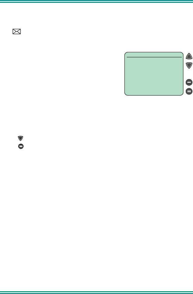
SRM9030 ~ PMR Mobile Radio User Guide
© TMC Radio 2007 9 TNM-U-E-0003 Issue 4
4.4 STORED CALLS SCREEN (SELCALL)
This screen allows the eight most recent missed Selcalls (ones not answered
before the Alert-tone stops) and received Status Selcalls to be reviewed.
The icon will show in the Main Channel Screen when there is an entry in
this Screen. A "Bip" tone is emitted every few seconds when a new call is
stored here.
The displayed text identifies the caller (e.g.
John Smith) and, if used, Status text (e.g.
Call Depot) is displayed on the Message
Line.
The displayed number (#05) shows the
queued position of the entry. The most recent
call is shown whenever this Screen is
displayed.
Press the Left/Right Arrow buttons to scroll through other Stored Calls.
Press the Green Handset to Voice Call the originator.
Press the Red Handset to return to the Channel Screen without making a
call.
Press (Del) to delete the viewed entry.
Press (OK) to go to the Channel Screen with the Call Dialstring ready for
editing, the keypad is enabled for this step.
Call Depot
#05
OK
Del
Stored Calls
John Smith
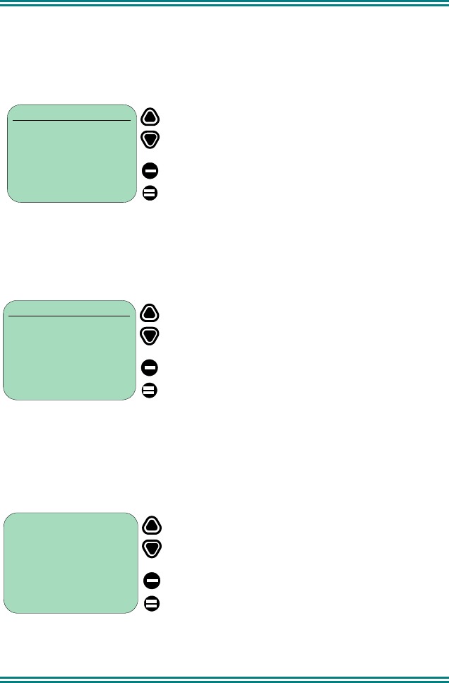
SRM9030 ~ PMR Mobile Radio User Guide
TNM-U-E-0003 Issue 4 Page 10 © TMC Radio 2007
4.5 STORED CALLS (TEXT MESSAGE)
Received text messages are stored in the Stored Calls screen. Text messages
may be up to 237 characters in length.
A Data message may also be displayed immediately when received if
configured to do so by the FPP.
Data Msg
Stored Calls
#01 Delete
ID: 00050 OK
The icon will show on the main channel screen when there is an entry in this
screen. A “bip” tone is emitted every few seconds when a text message is
stored here.
The displayed text identifies the caller (e.g. 01) by their data address. For
example “ID: 00050”.
If the caller is the dispatcher as defined by the FPP, the caller’s identity is not
shown.
When the message is selected, the screen shows the full message. If the
message exceeds the screen, a soft key titled “more” will allow access to the
other screen.
ID: 00050
AT WAREHOUSE
Data Msg
Stored Calls
#01 Delete
AT WAREHOUSE OK

SRM9030 ~ PMR Mobile Radio User Guide
© TMC Radio 2007 11 TNM-U-E-0003 Issue 4
A message may be deleted by pressing the “delete” soft
key.
Data Msg
Stored Calls
#01 Delete
AT WAREHOUSE OK
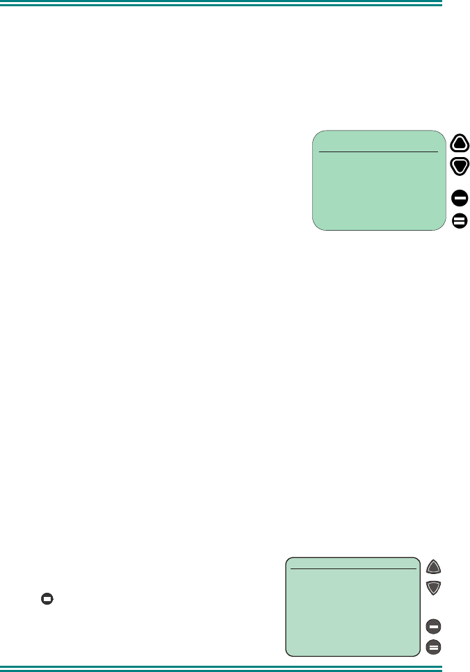
SRM9030 ~ PMR Mobile Radio User Guide
TNM-U-E-0003 Issue 4 Page 12 © TMC Radio 2007
4.6 SEND MESSAGE
This Screen allows the user to send a free form text message to another radio
user in a similar manner to a cell phone SMS.
Upon selecting the Send Message menu option with the OK button, a flashing
cursor will appear on the lower left hand corner of the screen.
Each key is labelled with up to 3 text characters. The
text characters are entered by pressing the keypad
key once for the first character, twice for the second
and three time for the third.
After a short delay, the cursor will advance for the
next character entry.
To move the cursor left or right, use the -/+ buttons.
To delete a character, move the cursor over the character and then press the
function key that is programmed with the Reset function.
When the message is complete, press the OK button to send it. The screen
will then ask for the address to send it to with “Enter No.” Enter the address
and then press OK. The message will be sent.
4.7 SETUP SCREEN
Use this Screen to access the other Setup
submenus.
Press (OK) or the Left/Right Arrow
buttons to show the first of the submenus, and
then the Up/Down Arrow buttons to scroll
through these screens.
OK
Setup
#01
Send Message
PICK UP OK
Delete

SRM9030 ~ PMR Mobile Radio User Guide
© TMC Radio 2007 13 TNM-U-E-0003 Issue 4
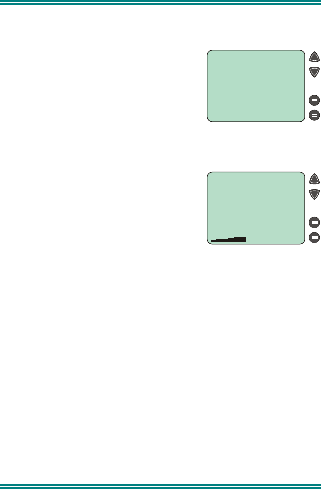
SRM9030 ~ PMR Mobile Radio User Guide
TNM-U-E-0003 Issue 4 Page 14 © TMC Radio 2007
5. COMMON FUNCTIONS AND FACILITIES
5.1 SWITCH-ON/SWITCH-OFF
Momentarily press the On/Off/Volume Knob
to switch the radio ON.
The display will illuminate and show a
‘Welcome Message’ and the Selcall Identity
of the radio.
After a brief time the display will revert to the
Channel Screen, at which time the radio is
ready for use.
Pressing and holding the On/Off knob for
approximately 2 seconds will switch the radio
Off.
If the radio Inactivity Timer is enabled, the
radio will automatically turn Off after several
hours of inactivity (i.e. no buttons pressed).
The radio will emit warning beeps for 10
seconds prior to switching off. Pressing any
button will reset this timer.
The radio can also be setup to switch on
automatically with the Vehicle Ignition
whenever the vehicle is started.
5.1.1 Volume Adjustment
The Volume Control adjusts the speech level at the loudspeaker or handset.
Rotating clockwise increases the volume and anti-clockwise decreases the
volume.
Note: The radio may be programmed so that the volume cannot be turned off
completely.
1 2 3 4
SRM90000
Depot
18
Mt Bigfoot
DTMF
Scan
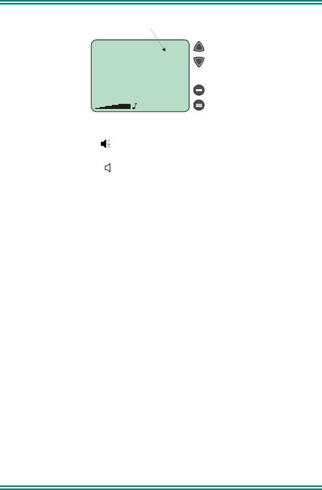
SRM9030 ~ PMR Mobile Radio User Guide
© TMC Radio 2007 15 TNM-U-E-0003 Issue 4
5.2 RECEIVING
The radio will listen on the displayed Channel.
The Solid Speaker Icon will show when a valid signal is being received and
audio will be heard at the Loudspeaker.
An Outline Speaker Icon will show if a signal is present but the audio is
muted for some reason (e.g. incorrect CTCSS tone, or the Selcall Mute is
closed).
Changing channels can be achieved by any of the following:
• Pressing the Left/Right Arrow buttons.
• Entering the desired channel number from the Keypad and pressing #
(e.g. 12#).
• Pressing a Go-to-Channel Function Button, refer to Section 7.11.
Note: If the displayed channel is a Vote or MultiAx channel then the Rotating
Arrow symbol will be displayed while the radio is searching for a signal.
When stopped on a channel the Rotating Arrow disappears and the
selected Channel Name is shown on the Message Line.
Channel
No.
ICON
LABEL 1
Scan Groups
1 2 3 4
LABEL 2
Channel Name
MESSAGE LINE
LABEL 3
LABEL 4

SRM9030 ~ PMR Mobile Radio User Guide
TNM-U-E-0003 Issue 4 Page 16 © TMC Radio 2007
5.3 TRANSMITTING
To avoid interfering with other users of the channel, listen first to ensure no
transmissions are occurring. Make sure that the Outline Speaker Icon is
not shown.
Hold the microphone a few centimetres from the mouth, press the “Press to
talk” (PTT) switch and note that the Tx-LED is RED. Speak clearly across the
face of the microphone in a normal conversational manner.
In most systems it is important to wait a short time between pressing PTT and
commencing to speak. This ensures that the path is properly established and
avoids lost or distorted speech.
Use the correct operating procedure and keep transmissions short.
Release the PTT switch as soon as the message is finished.
Notes: 1 A channel may be programmed as “Receive-only” or “Transmit
Inhibit” may be programmed which disallows PTT while the radio is
receiving a signal. A continuous tone will be heard if PTT is
attempted.
2 A Transmit Limit Timer may be setup that limits a continuous
transmission on a channel. The last 10 seconds before the timer
expires may be accompanied by warning tones.
3 The radio may be programmed to send a Selcall (ANI) when the
PTT is pressed or released. This may introduce a short delay before
the microphone is enabled or after PTT is released.
5.3.1 VOX Operation
If Voice Operated Transmit (VOX) is enabled, and the hands-free microphone
is fitted, the radio will automatically transmit all speech it hears and then return
to receive.

SRM9030 ~ PMR Mobile Radio User Guide
© TMC Radio 2007 17 TNM-U-E-0003 Issue 4
5.4 SELCALL FUNCTIONS
5.4.1 Receiving a Selcall
A number of different options can be set up by your dealer to sound various
alert tones when a selcall is received. Consult your dealer for a detailed
explanation of your radios set up.
When a Selcall is received the radio may respond by:
• Showing a flashing or solid icon to indicate that the radio has been
Called or is On-call,
• Sounding an Alert tone, or
• Displaying the Name of the caller (if it exists in the Phonebook) or the
numerical identity of the caller (if unknown) in the Name field.
Pressing PTT and/or removing the Microphone from its Cradle will change the
state of the icon, stop the Alert tone and enable the speaker audio.
Replacing the Microphone back into its Cradle will clear the icon (and/or
mute the speaker).
5.4.2 Sending a Selcall
Refer to sections on Phonebook Screen (page 7) and Status Screen (page 8)
for methods of sending a Selcall.
5.4.3 Other Selcall Functions
The SRM9030 has several other functions that affect how the radio operates
with received signals or selcalls. These are described later in this booklet
under the headings:
Monitor/Reset (refer to Section 7.1)
Reset (refer to Section 7.3)
Transpond Enable (refer to Section 7.7)
Send-1, Send-2 (refer to Section 7.6)
Special Encode1...8 (refer to Section 7.12)
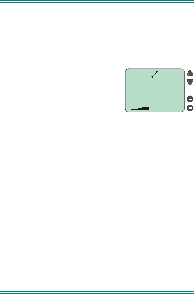
SRM9030 ~ PMR Mobile Radio User Guide
TNM-U-E-0003 Issue 4 Page 18 © TMC Radio 2007
5.5 SCAN FUNCTIONS
Scanning consists of sequentially searching up to 15 channels for a valid
signal (RF, CTCSS or DCS tone). When found the radio will stop on that
channel until the signal disappears again.
The Microphone needs to be in the cradle, (on hook) for the radio to scan.
While listening on the channel, the User can PTT on that channel. After the
signal disappears the radio will remain listening on the channel for a short time
(typically 3 seconds) before resuming scanning. PTT is inhibited while the Mic
is in cradle.
If a Priority/Emergency Channel is
assigned, the radio will interleave a check of
this channel between each normal channel
check. The radio may also check the Priority
Channel every few seconds while stopped on
a channel. If a signal is found on the Priority
Channel then the radio will switch to that
channel immediately.
If programmed, the Priority Channel is automatically selected when the
Microphone is removed from cradle.
To activate Scanning, press the SCAN Function button from the Main Channel
Screen.
1
Func 1
Skip
Scan RSE
MESSAGE LINE
Edit
Exit

SRM9030 ~ PMR Mobile Radio User Guide
© TMC Radio 2007 19 TNM-U-E-0003 Issue 4
5.5.1 Scan Screen
The display shows the name of the current Scan-Group (e.g. “Scan RSE”),
which can be changed using the Left/Right Arrow buttons. The Scan-Group
Number is shown at the top-left of the display, i.e. 1…4 if it is a User Scan-
Group, or blank for Fixed Scan-Groups. While the Scan Screen is displayed
the radio is scanning the shown group.
The Scan Screen does not time-out. Normal exit is via Exit.
The RSSI indicator shows the received signal strength as the radio is
scanning.
The Function button has the same assignment as in the Main Channel
Screen.
The (Orange button) and F6 (on Microphone) are both still active.
The , and buttons are reassigned as shown.
When stopped on a channel, the Message-Line shows the name of the
selected site, and the “rotating arrow” symbol is replaced by the Speaker
symbol.
Skip temporarily deletes the channel from the Scan-Group. Skip is only
shown when stopped on a channel and the Microphone is in Cradle. Skipped
channels are restored when a different Scan Group is selected or if Scan is
exited. The Priority Channel cannot be skipped.
“Edit” is only shown for User Scan Groups and opens up the Scan-Edit Screen
for the selected Scan-Group allowing Channels to be added, deleted or set as
the priority channel (see below).
While listening on the channel, the User can PTT on that channel. After the
signal disappears (or Microphone is placed back in Cradle) the radio will
remain listening on the channel for a short time before resuming scanning.
The Microphone needs to be in cradle for the radio to scan. If the Microphone
is left off-cradle for too long then the radio will sound a continuous alert tone
until it is replaced.
If the radio is not stopped on a channel (and no Priority channel is defined)
when the Mic is removed from Cradle, then the channel shown on the display
prior to “Scan” being activated is selected.
DTMF (if enabled) is only active when the Mic is out of cradle.
The Up/Down Scroll Buttons allow access to the other Screens (not Main
Channel Screen). When these other menus time out they return to the Scan
Screen.
The Keypad may NOT be used for quick channel change (e.g. 456#) in this
Screen.

SRM9030 ~ PMR Mobile Radio User Guide
TNM-U-E-0003 Issue 4 Page 20 © TMC Radio 2007
5.5.2 Scan-Edit Screen
In the Scan-Edit Screen the display shows the Channel List (excluding Vote
and MultiAx channels) and the Message-Line shows either “Member”, “Priority”
or is blank for channels that are not scanned.
Press (Prty) to make the displayed
Channel the Priority Channel (replacing any
previous Priority Channel assignment, which
is then made a normal member of the group).
Press (Add) to add the displayed
Channel. If the Scan-Group is full, then error-
beeps sound.
Press (Del) to remove the displayed Channel.
Press (OK) to exit back to the Scan Screen (like Red-Handset).
Scroll Buttons are used to select the channels.
Keypad allows Channel-Change strings (e.g. 456# goes to Channel 456) to
valid channels that may be included in the Scan Group (i.e. not Vote or MultiAx
channels).
5.6 MUTE LEVEL SETTING
When the Mute Adjust Screen is selected the Left/Right Arrow buttons allow
the displayed Radio Mute level to be adjusted. The level is stored when the
Screen is exited.
5.7 DTMF OPERATION
When DTMF is enabled, DTMF tones can be sent using the Keypad from the
Main Channel Screen. Pressing 0...9, * and # will send the associated tones.
The tone period and gap are set by the programmer.
DTMF can be enabled in several ways:
• Via the DTMF option in the User-Options sub-menu under the SETUP
Menu (refer to Section 6).
• If the DTMF Function is assigned to a F1...4 button, DTMF is enabled when
the button indicator is ON.
19
12 4
Prty
Del
Mt Bigfoot
Member
Add
OK

SRM9030 ~ PMR Mobile Radio User Guide
© TMC Radio 2007 21 TNM-U-E-0003 Issue 4
5.8 EXTERNAL ALERT
Provision is made to connect an external alerting device to the rear of the
radio. The external alert may be activated when a selcall is received (and
cancelled by a timeout, user intervention or receiving a different selcall).
This function is enabled by software programming. When enabled, the
External Alert may be switched On or Off using a Function button. A Chevron
is displayed next to the button Label when the function is On.
5.9 AUXILIARY OUTPUT
Provision is made for connection to an Auxiliary Output on the rear of the radio.
This output is enabled by software programming and can be used to activate
an external device. When enabled, the function is toggled On/Off using a
Function button. A chevron is displayed on the Main Menu when the function
is toggled On.

SRM9030 ~ PMR Mobile Radio User Guide
TNM-U-E-0003 Issue 4 Page 22 © TMC Radio 2007
6. SETUP
The Setup sub-menus allow the operator to edit/modify the operation of some
of the general functions of the radio. The programmer can restructure or
restrict access to any or all of these menus and may restructure them
according to specific requirements.
6.1 SETUP SUB-MENUS
The Setup sub-menu structure programmed at manufacture is shown in Figure
2. These sub-menu Screens provide access to operator functions as follows.
User Options Key beeps, Backlight, Dual Watch & DTMF on/off
selection.
Mute Adjust Mute Level adjustment.
Phone Book Edit Allows Phonebook entries to be changed, deleted or
added.
Contrast Display contrast adjustment.
Alert Volume Beep tone level setting (relative to Audio Volume).
Radio Information Programmer File description, SW version and Serial
Number.
Network Trunk Network-1/2 or Conventional Channel selection.
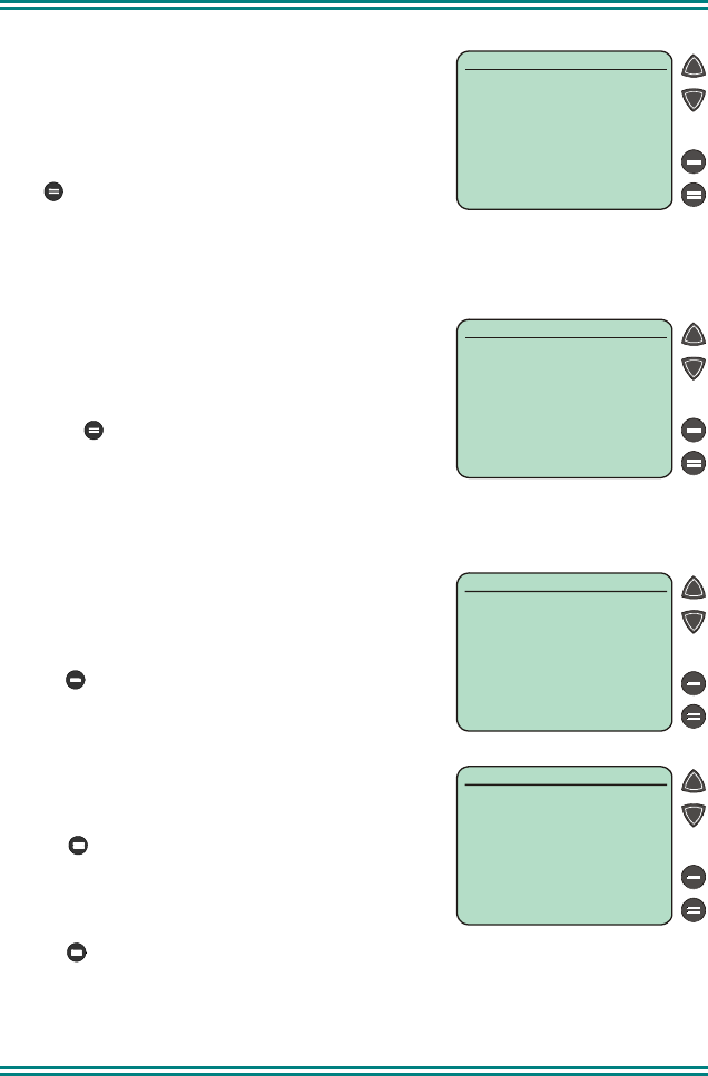
SRM9030 ~ PMR Mobile Radio User Guide
© TMC Radio 2007 23 TNM-U-E-0003 Issue 4
6.1.1 User Options
The User Options Screen allows the Keybeeps,
Backlight, Dual Watch and DTMF facilities to be
set On or Off.
Use the Left/Right Arrow buttons to scroll
between the different facilities.
The (Alter) button toggles the selection
On/Off.
The setting is saved on exit.
6.1.2 Mute Adjust
Use the Menu Screen to view and change
current Mute setting.
Use the Left/Right Arrow buttons to change the
Mute level.
Use the (OK) button to return to the Channel
Screen.
Note: When a Voting channel is selected the Voting-Mute
level is shown, but may not be changed.
6.1.3 Phone Book Edit
This Screen allows you to delete or edit Phone
Book entries, or add a new entry.
6.1.3.1 ADD A NEW ENTRY
Press (Add) to add a new entry.
The next available Index number is displayed.
Use the keypad to type the dialstring for the new
entry.
Use the Red Handset to backspace/clear
incorrect entries.
Press (OK) to accept the number and
display the next screen.
Use the keypad to type the name (refer to
Section 6.1.3.4).
Press (OK) to accept the name and go to
the Main Channel Screen.
2345
#02
Add
Edit
Del
Phone Book Edit
John Smith
Enter No
#31
OK
Phone Book Edit
On
Alter
User Options
Key Beeps
04
OK
Mute
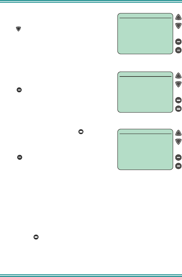
SRM9030 ~ PMR Mobile Radio User Guide
TNM-U-E-0003 Issue 4 Page 24 © TMC Radio 2007
6.1.3.2 DELETE AN ENTRY
Use the Left/Right Arrow buttons to scroll to the
desired phone book entry.
Press (Del) to delete the current entry and
return to the Channel Screen.
6.1.3.3 EDIT AN EXISTING ENTRY
Use the Left/Right Arrow buttons to scroll to the
Phonebook Entry to be edited.
Press (Edit) to select the entry and present
the number for editing.
(Use the Red Handset to backspace/clear an
entry.)
Type the new number and press (OK) to go
to the Name Edit Screen.
Edit the name, refer to Section 6.1.3.4.
Press (OK) to accept the changes.
6.1.3.4 USING THE KEYPAD
When using the keypad to type text:
• Press the appropriate keypad button a number of times until the desired
character or number is selected,
• The current character space is identified by a flashing block cursor,
• Use */# to select lower/upper case letters, respectively,
• Use the Left/Right Arrow buttons to move to the next or previous
character space to be entered/modified, and
• Press to accept and go to the next Screen.
Richard
#02 Add
OK
Del
Phone Book Edit
Richard
3456
#02
Add
Edit
Del
Phone Book Edit
Richard
2345
#02
Add
Edit
Del
Phone Book Edit
John Smith
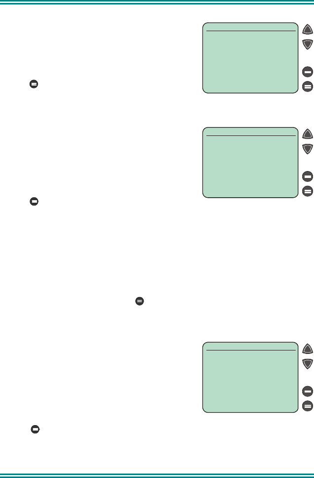
SRM9030 ~ PMR Mobile Radio User Guide
© TMC Radio 2007 25 TNM-U-E-0003 Issue 4
6.1.4 Contrast
The Contrast Screen allows you to set the
contrast level of the Display in the range from 0
to 15.
Use the Left/Right Arrow buttons to select the
required level.
Press (OK) to accept the setting and go to
the Channel Screen.
6.1.5 Alert Volume
This Screen allows you to set the level of the
Alert Volume Beep Tone in relation to the current
Volume setting. The level can be set in 63 steps
over the range -31 to +30.
Use the Left/Right Arrow buttons to change the
relative alert level
Press (OK) to accept the setting and go to
the Channel Screen.
Note: A minimum Alert Level may be set to ensure the Alerts can always be
heard from the speaker.
6.1.6 Information
This Screen displays information that identifies the Programmer File
description, Software Version and Radio Serial Number.
This is a read only Screen, press to go to the Channel Screen.
6.1.7 Network
The Network Screen allows you to switch
operation between;
• Trunk Network 1
• Trunk Network 2 or
• PMR.
Use the Left/Right Arrow buttons to make your
selection.
Press (OK) to accept that selection and go to the Channel Screen.
Refer to the Trunk Operating Instructions for Trunk operation.
10
OK
Contrast
00
OK
Alert Volume
OK
Network
PMR

SRM9030 ~ PMR Mobile Radio User Guide
TNM-U-E-0003 Issue 4 Page 26 © TMC Radio 2007
7. SPECIAL FUNCTION BUTTONS
This section lists Functions that may be programmed to the F1, F2, F3, F4, F5
or F6 buttons.
Consult your TMC Radio Dealer for which functions have been programmed in
to your radio.
7.1 MONITOR
Opens/Closes the audio (signaling) mute.
Only valid on Non-Community Repeater type channels and/or Closed Selcall
channels without Receiver Lock-out programmed.
7.2 SQUELCH DEFEAT
Opens/Closes the squelch (carrier) mute.
7.3 RESET
Closes the audio (signaling) mute on closed Selcall Channels.
7.4 SCAN
Activate Scanning, refer to Section 5.5.
7.5 AUXILIARY
Toggle the external output, refer to Section 5.9.
7.6 SEND-2
Sends a specific selcall sequence.
7.7 TRANSPOND
Enables/Disables Individual Call Acknowledge.
7.8 CTCSS
Defeats the CTCSS mute on the channel
Only valid on Non-Community Repeater type channels and/or Open Selcall
channels.
7.9 MUTE
Provides direct access to the Mute Setup screen (refer to Section 6.1.2) and
allows the user to change the mute level from that screen.
7.10 EXTERNAL ALERT
Enables/Disables control of External Output via Selcall Decodes, refer to
Section 5.8.

SRM9030 ~ PMR Mobile Radio User Guide
© TMC Radio 2007 27 TNM-U-E-0003 Issue 4
7.11 GO TO CHAN A, B, C, D
Selects predefined Channel A, B, C or D, and returns on the second press.
The Defined Channel is redefined if held for approximately 2 seconds.
7.12 SPECIAL ENC 1…8
Sends Special Encode 1, 2, … 8
7.13 ALARM
Put the mobile into Alarm mode.
7.14 REPEATER DEFEAT
Allows the radio to transmit on the reverse frequency on a Repeater Channel.
When the button is pressed again (or the Channel is changed) the transmit
frequency reverts to the original setting.
7.15 LOW POWER
Forces the radio to low power.
Pressing again puts the radio back to the power level defined for the current
channel. This is not affected by Channel changes.
7.16 HANDSFREE (VOX)
Toggles the VOX function for the Handsfree Microphone.
7.17 DTMF MODE
This function places the numeric keypad into DTMF mode, refer to Section 5.7.
7.18 SCRAMBLER ON/OFF
If enabled by the Field Programmer, this function toggles the state of the
speech scrambler. When active, there will be a short audible tone at the start of
PTT to inform the user of the scrambler activation. Each time the key is
pressed, the display will show “On” and “Off”.

SRM9030 ~ PMR Mobile Radio User Guide
TNM-U-E-0003 Issue 4 Page 28 © TMC Radio 2007
8. OPTIONS
The following options are available, contact your dealer for further information.
8.1 QUICK RELEASE TRANSCEIVER KIT
This kit provides a mounting cradle to allow the Transceiver to be quickly
removed without having to undo unnecessary screws.
8.2 MICROPHONE/CONTROL HEAD EXTENSION LEAD
This lead allows the Transceiver to be placed up to 4.5 metres from the Control
Head.
8.3 VOX HANDSFREE OPTION
This allows a driver to use the radio without having to lift the microphone or
press any buttons.
8.4 TYPE 1 PARALLEL I/O EXPANSION OPTION
This option provides eight I/O lines and pre/de-emphasised audio to allow
external interfacing to the radio.
8.5 INTERNAL GPS OPTION
This provides Global Position reporting for Trunk and PMR applications.
8.6 CROSS-LINKED CABLE
This is used with various applications to cross-connect or interconnect
Transceivers or Control Heads.
8.7 600 OHM INTERFACE OPTION
This provides a balanced 600 Ohm 2/4 wires audio interface and opto-isolated
E and M lines.
8.8 TYPE 2 I/O OPTION
This interface board is designed for multiple Transceivers or Control Heads.
8.9 DUAL CONTROL HEAD OPTION
This allows two Control Heads to be used from one Transceiver.
8.10 DUAL TRANSCEIVER OPTION
This allows two transceivers to be used with one Control Head.
8.11 DESK TOP BASE KIT
This provides a housing for the radio and incorporates an 8 Amp Power Supply
Unit and speaker.

SRM9030 ~ PMR Mobile Radio User Guide
© TMC Radio 2007 29 TNM-U-E-0003 Issue 4
9. TROUBLESHOOTING
If, after reading this guide, you are unable to switch the radio on, check the
following:
• A fuse has not blown.
Your installer should advise you of the location of the two main fuses,
• The power supply cables and their connections are secure, and
• The vehicle battery is charged.
If these checks are OK, contact your dealer or TMC Radio representative for
further advice.
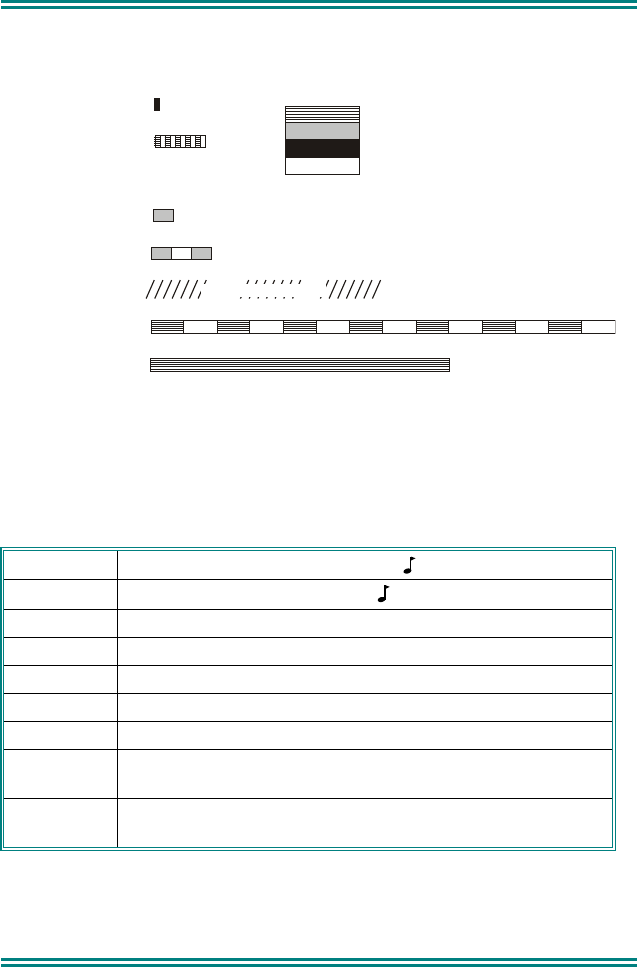
SRM9030 ~ PMR Mobile Radio User Guide
TNM-U-E-0003 Issue 4 Page 30 © TMC Radio 2007
Appendix A - Alert Tones and Messages
Figure 3 - Alert Tones
These messages are displayed on the Message Line to give the user
additional information.
Called Indicates Selcall state (for flashing icon).
On Call Indicates Selcall state (for solid icon).
Queued A Selcall is queued waiting to be sent.
Voting Additional information about the Channel type.
MultiAx Additional information about the Channel type.
Scanning Additional information about the Channel type.
Dual Watch Dual Watch function is enabled.
Member Scan Edit: Indicates that the displayed channel is a member
of the current Scan Group.
Priority Scan Edit: Indicates that the displayed channel is the Priority
Channel in the current Scan Group.
Key Beep
Error Tone
Beep Alert
Bip Alert
Ring Alert
Urgent Alert
Continuous Alert
2 x Bip Alert
0.0
5
9000_52
0.10
0.05
0.10
0.10
Continuous
Telephone Ring Tone
0.19
Duration Indicated in seconds
880 Hz
Off
1480 Hz
440 Hz

SRM9030 ~ PMR Mobile Radio User Guide
© TMC Radio 2007 31 TNM-U-E-0003 Issue 4
Appendix B - Glossary
A summary of common radio terms and some other terms used in this
document, and their meanings, are given below.
Indicator When displayed next to a Function, indicates an
event.
Alert tones The transceiver emits these tones to indicate an
invalid operator or error.
Cradle The bracket that holds the microphone when it is
not in use (on hook).
Current
Phonebook Entry
Name that would be shown were the Phonebook
screen shown.
DSP
Digital Signal Processor.
DTMF Dual Tone Multi-Frequency (Signaling Method).
LCD Liquid crystal display.
MIC Abbreviation for microphone.
MPT1327 Refers to the UK Ministry for Post and
Telecommunications specification defining the low
level protocol for public trunking systems.
MPT1343 Refers to the UK Ministry for Post and
Telecommunications specification defining the User
Interface for radios operating on MPT1327 public
trunking systems.
Network The trunking infrastructure and all its
interconnections.
PTT Press-to-Talk. Hold down the Press-to-talk switch
on the microphone for the duration of the
transmission.
RF Radio Frequency.
RSSI Received Signal Strength Indicator
Saved Status
Value
The last Status that was sent, entered or optionally
received.

SRM9030 ~ PMR Mobile Radio User Guide
TNM-U-E-0003 Issue 4 Page 32 © TMC Radio 2007
Appendix C – Compliance with RF Energy Exposure
Guidelines (United States and Canada)
RF ENERGY EXPOSURE AWARENESS AND CONTROL INFORMATION
AND OPERATIONAL INSTRUCTIONS FOR FCC OCCUPATIONAL USE
REQUIREMENTS.
Before using your TMC Radio mobile two-way radio, read this important RF
energy awareness and control information and operational instructions to
ensure compliance with the FCC’s RF exposure guidelines.
NOTICE: This radio is intended for use in Occupational/ controlled
conditions in a mobile application where users have full knowledge of
their exposure and can exercise control over their exposure to meet FCC
limits. This radio device is NOT authorised for general population,
consumer, or any other use.
This two-way radio uses electromagnetic energy in the radio frequency (RF)
spectrum to provide communications between two or more users over a
distance. It uses radio frequency (RF) energy or radio waves to send and
receive calls. RF energy is one form of electromagnetic energy. Other forms
include, but are not limited to, electric power, sunlight and x-rays. RF energy,
however, should not be confused with these other forms of electromagnetic
energy, which when used improperly can cause biological damage. Very high
levels of x-rays, for example, can damage tissues and genetic material.
Experts in science, engineering, medicine, health and industry work with
organizations to develop standards for exposure to RF energy. These
standards provide recommended levels of RF exposure forboth workers and
the general public. These recommended RF exposure levels include
substantial margins of protection. All two-way radios marketed is North
America are designed, manufactured and tested to ensure they meet
government established RF exposure levels. In addition, manufacturers also
recommend specific operating instructions to users of two-way radios. These
instructions are important because they inform users about RF energy
exposure and provide simple procedures on how to control it. Please refer to
the following websites for more information on what RF energy exposure is and
how to control your exposure to assure compliance with established RF
exposure limits.
http:l/www.fcc. gov/oet/rfsafety/rf-fags. htm 1
http://www.osha.gov/SLTC/radiofrequencvradiation/index.htmi

SRM9030 ~ PMR Mobile Radio User Guide
© TMC Radio 2007 33 TNM-U-E-0003 Issue 4
Federal Communications Commission Regulations:
The FCC rules require manufacturers to comply with the FCC RF energy
exposure limits for mobile two-way radios before they can be marketed in the
U.S. When two-way radios are used as a consequence of employment, the
FCC requires users to be fully aware of and able to control their exposure to
meet occupational requirements. An exposure awareness label is attached to
the equipment directing users to specific awareness information.
Compliance with RF Exposure Standards
Your TMC two-way radio is designed to comply with a number of national and
international standards and guidelines (listed below) regarding human
exposure to radio frequency electromagnetic energy. This radio complies with
the IEEE (FCC) and ICNIRP exposure limits for Occupational/ Controlled RF
exposure environment at duty factors of up to 50% talk 50% listen and is
authorised by the FCC for occupational use. In terms of measuring RF energy
for compliance with the FCC exposure guidelines, your radio radiates
measurable RF energy only while it is transmitting (during talking), not when it
is receiving (listening) or in standby mode.
Your TMC Radio two-way radio complies with the following RF energy
exposure standards and guidelines:
• United States Federal Communications Commission, Code of Federal
Regulations; 47CFR part 2 sub-part J
• American National Standards Institute (ANSI) / Institute of Electrical
and Electronic Engineers (IEEE) C95. 1-1992
• Institute of Electrical and Electronic Engineers (IEEE) C95.1-1999
Edition

SRM9030 ~ PMR Mobile Radio User Guide
TNM-U-E-0003 Issue 4 Page 34 © TMC Radio 2007
RF Exposure Compliance and Control Guidelines and
Operating Instructions
To control exposure to yourself and others and ensure compliance with the
Occupational/ Controlled environment exposure limits always adhere to the
following procedures.
Guidelines:
• User awareness instructions should accompany the device when
transferred to other users.
• Do not use this device if the operational requirements described
herein are not met.
Instructions:
• Transmit no more than the rated duty factor of 50% of the time. To
transmit (talk), push the Push-To-Talk button. To receive calls,
release the PTT button. Transmitting 50% of the time, or less, is
important because this radio generates measurable RF energy
exposure only when transmitting (in terms of measuring for standards
compliance).
• Transmit only when people outside the vehicle are at least the
recommended minimum lateral distance away, as shown in Tables 1
and 2, from a properly installed according to installation instructions,
externally-mounted antenna.
NOTE- Table 1a) lists the recommended minimum lateral distance for
bystanders in an uncontrolled environment from the transmitting antenna for
the SRM9000AC (150MHz-174MHz) mobile rated power (25 watts) installed in
a vehicle. Table 1b) lists the recommended minimum lateral distance for
occupational/ controlled use.
Table 2a) lists the recommended minimum lateral distance for bystanders in an
uncontrolled environment from the transmitting antenna for the SRM9000UW
(440MHz-512MHz) mobile rated power (25 watts) installed in a vehicle. Table
2b) lists the recommended minimum lateral distance for occupational/
controlled use.

SRM9030 ~ PMR Mobile Radio User Guide
© TMC Radio 2007 35 TNM-U-E-0003 Issue 4
Table 1a). Rated Power and Recommended Lateral Distance for
General Population uncontrolled exposure for SRM9000AC
(150MHz to 174MHz).
Rated Power of Vehicle-
installed Mobile Two-way
Radio
Recommended Minimum
Lateral Distance from
Transmitting Antenna
25 watts with λ/4 dipole
(2.14dBi gain)
90cm (35.5 inches)
Table 1b). Rated Power and Recommended Lateral Distance for
Occupational/ Controlled exposure for SRM9000AC
(150MHz to 174MHz).
Rated Power of Vehicle-
installed Mobile Two-way
Radio
Recommended Minimum
Lateral Distance from
Transmitting Antenna
25 watts with λ/4 dipole
(2.14dBi gain)
40cm (15.75 inches)
Table 2a). Rated Power and Recommended Lateral Distance for
General Population uncontrolled exposure for SRM9000UW
(440MHz to 512MHz).
Rated Power of Vehicle-
installed Mobile Two-way
Radio
Recommended Minimum
Lateral Distance from
Transmitting Antenna
25 watts with λ/4 dipole
(2.14dBi gain)
75cm (29.5 inches)
Table 2b). Rated Power and Recommended Lateral Distance for
Occupational/ Controlled exposure for SRM9000UW
(440MHz to 512MHz).
Rated Power of Vehicle-
installed Mobile Two-way
Radio
Recommended Minimum
Lateral Distance from
Transmitting Antenna
25 watts with λ/4 dipole
(2.14dBi gain)
34cm (13.5 inches)

SRM9030 ~ PMR Mobile Radio User Guide
TNM-U-E-0003 Issue 4 Page 36 © TMC Radio 2007
Vehicle Installation Instructions:
The antenna(s) used for the SRM9000series of mobile two-way radios must be
installed to provide a separation distance of at least 75cm from all persons for
SRM9000UW (440-512MHz) and 90cm for SRM9000AC (150-174MHz). The
gain of the antenna(s) may not be greater than 0dBd (2.14dBi).
If the required separation distance extends beyond the physical boundary of
the vehicle, the antenna must be installed on the center of the roof ONLY and
must be installed in a vehicle having the following characteristics in order to
prevent bystanders from being exposed to levels exceeding the limits set for
General Population/ Uncontrolled exposure environment:
• All passengers must be sitting under a solid metal roof
• The rooftop width must be at least 150cm (59 inches) for
SRM9000UW (440-512MHz), or 180cm (71 inches) for
SRM9000AC (150-174MHz).
Mobile Antenna:
• Install the antenna at the center of the roof or the center of the trunk
deck, taking into account the bystander exposure conditions of
backseat passengers and recommended minimum lateral distances in
Table 1a) and 2a). These mobile antenna installation guidelines are
limited to metal body motor vehicles or vehicles with appropriate
ground planes.
• The antenna installation must additionally be in accordance with:
a.) The requirements of the antenna manufacturer/supplier
b.) Instructions in the Radio Installation Manual, including minimum
antenna cable lengths.
c.) The installation information of how to install the antenna to
facilitate recommended operating distances to all potentially exposed
persons.
• Use only TMC Radio approved supplied antenna or TMC Radio
approved replacement antenna. Unauthorized antennas,

SRM9030 ~ PMR Mobile Radio User Guide
© TMC Radio 2007 37 TNM-U-E-0003 Issue 4
modifications, or attachments could damage the radio and may violate
FCC regulations.
Approved Accessories
• This radio meets the FCC RF exposure guidelines when used with the
TMC Radio accessories supplied or designated for the product. Use
of other accessories may not ensure compliance with the FCC’s RF
exposure guidelines and may violate FCC regulations.
• To obtain a list of TMC Radio approved accessories see contact
details below or visit the following website which lists approved
accessories: http://www.tmcradio.com
Contact Information
For additional information on exposure or other information, please contact
TMC Radio Pty. Ltd.
1270 Ferntree Gully Road
Scoresby
Victoria, 3179
Australia
Telephone +61 3 9730 3800
Facsimile +61 3 9730 3968
Email orderdesk@tmcradio.com
Website www.tmcradio.com

© TMC Radio 2007 TNM-U-E-0003 Issue 4
Hereby, TMC Radio declares that this product is in compliance
with the essential requirements and other relevant provisions
of Directive 1999/05/EC.