Simoco Wireless Solutions SRP9100AC VHF PORTABLE TRANSCEIVER User Manual SERVICE MANUAL
Simoco Australasia Pty Ltd VHF PORTABLE TRANSCEIVER SERVICE MANUAL
UserManual.wiki
>
Simoco Wireless Solutions
>
SRP9100AC User Manual
>
SERVICE MANUAL
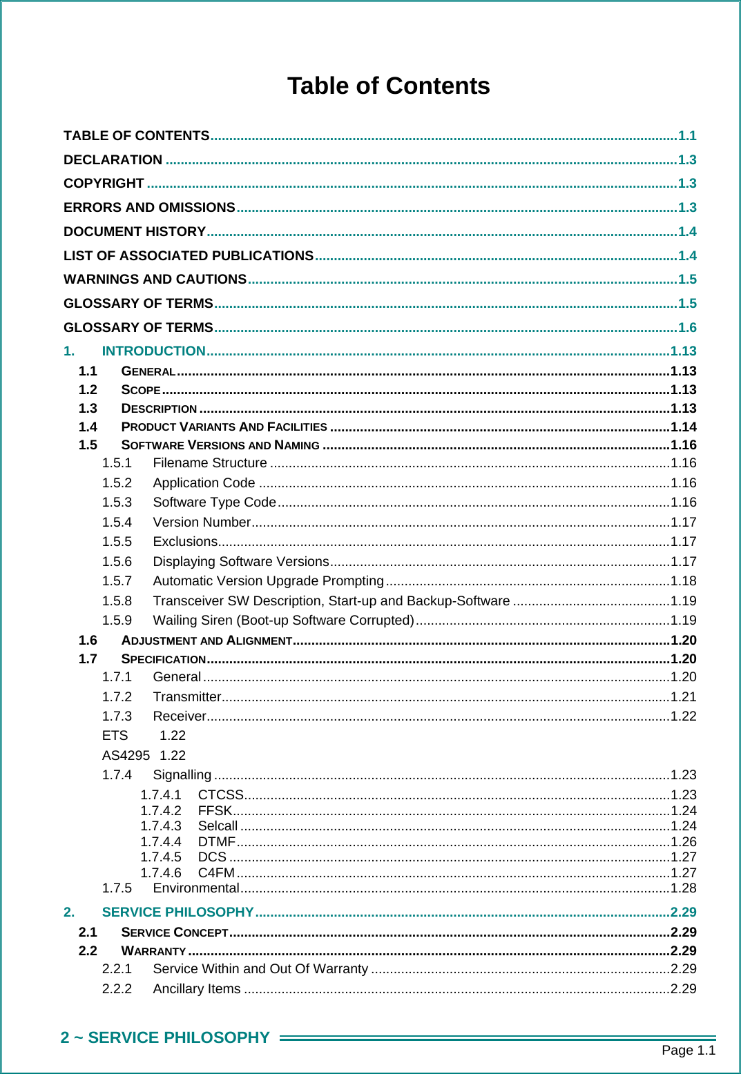
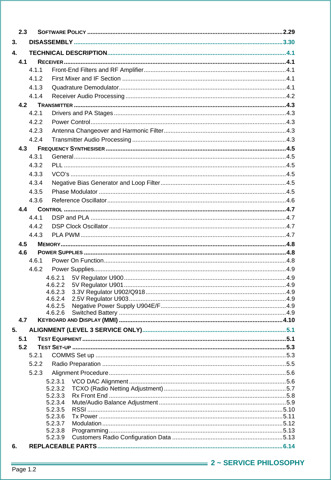
Contents
1.
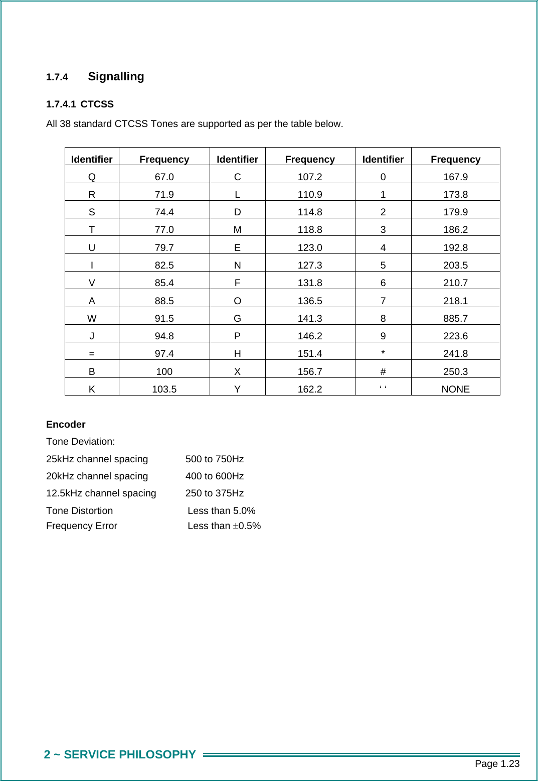
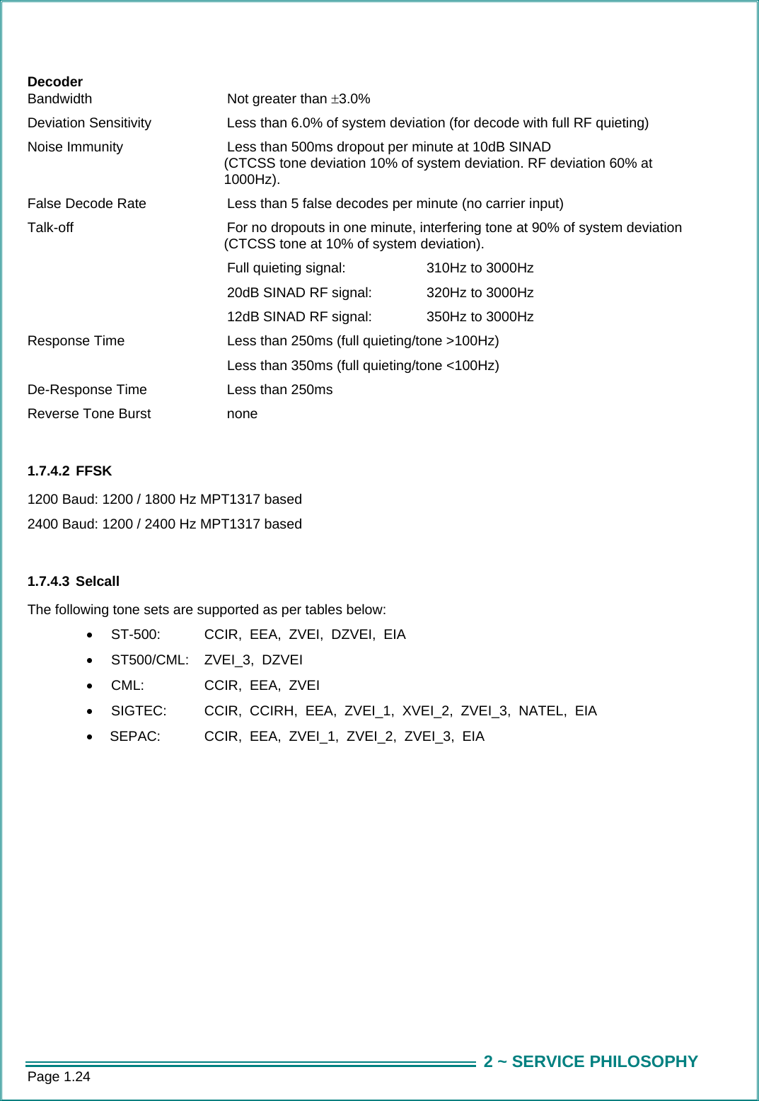
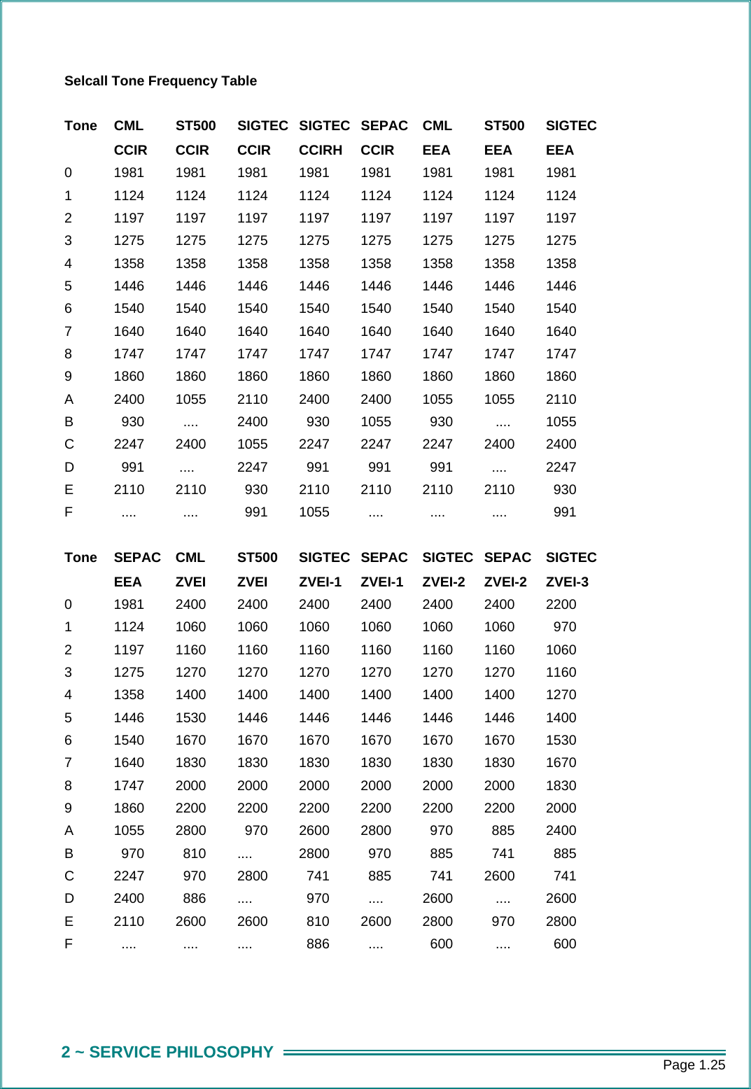
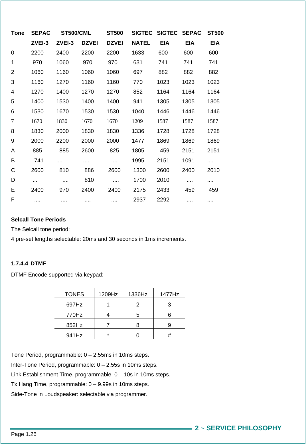
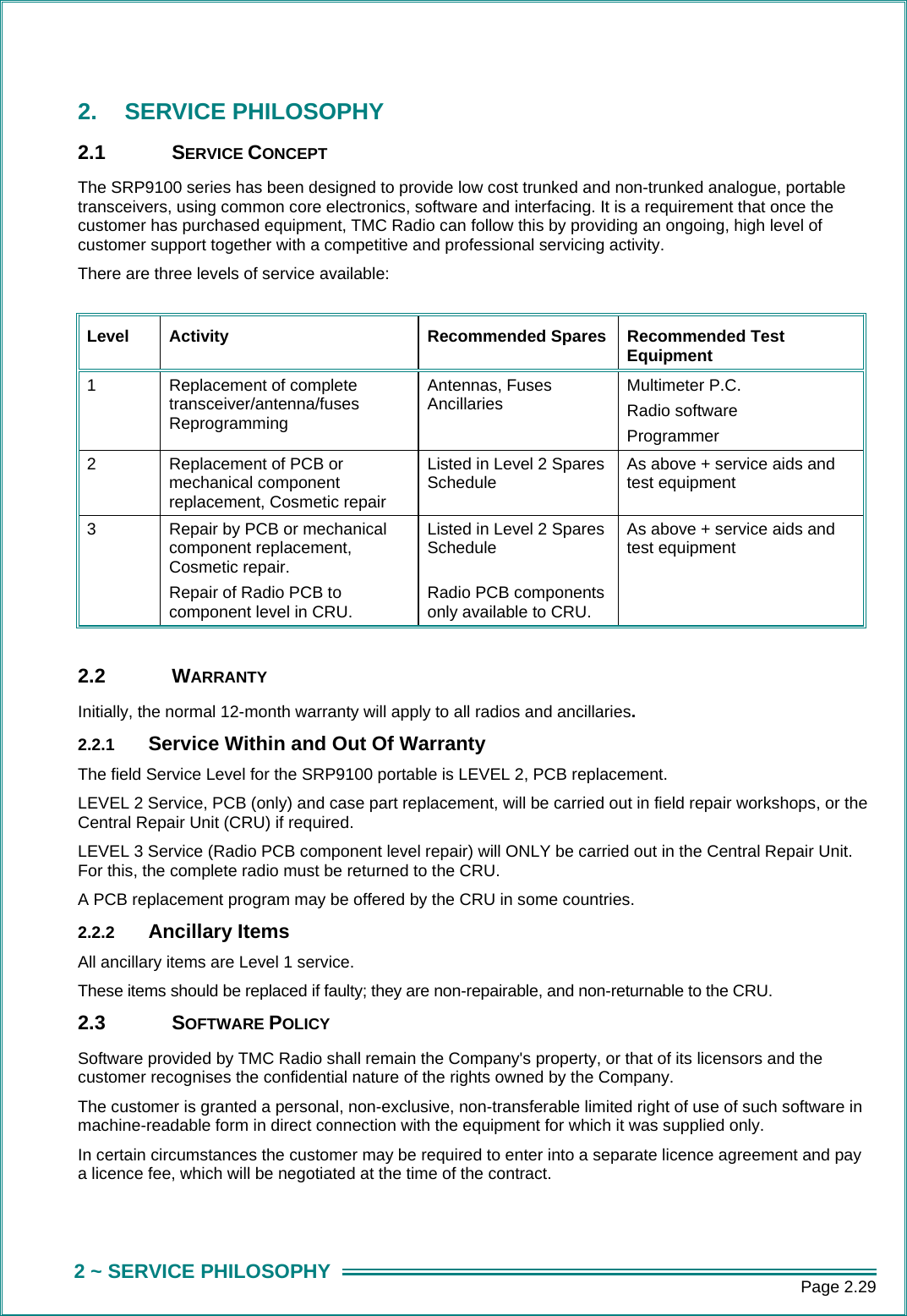
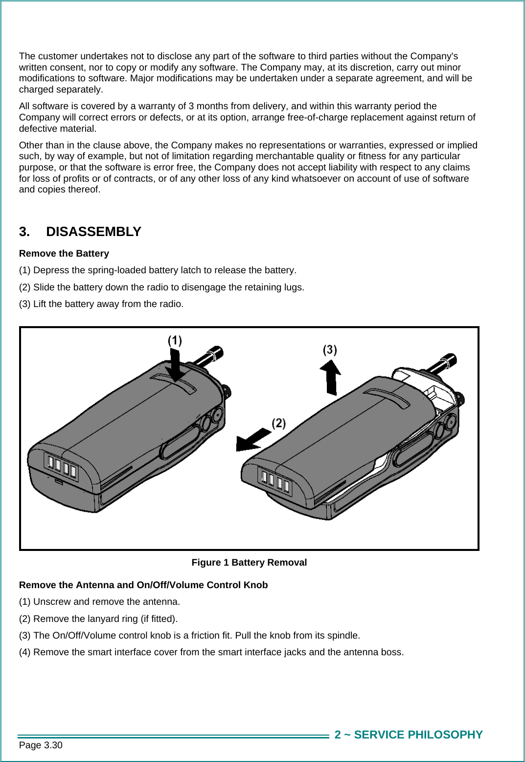
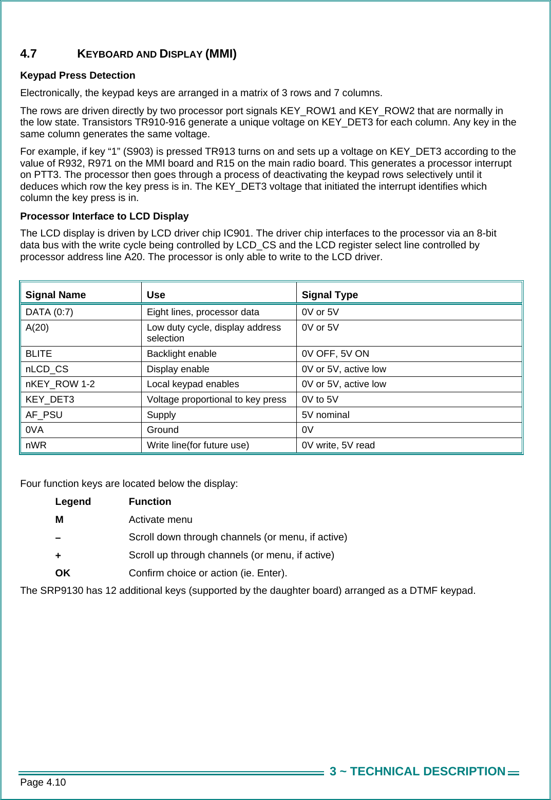
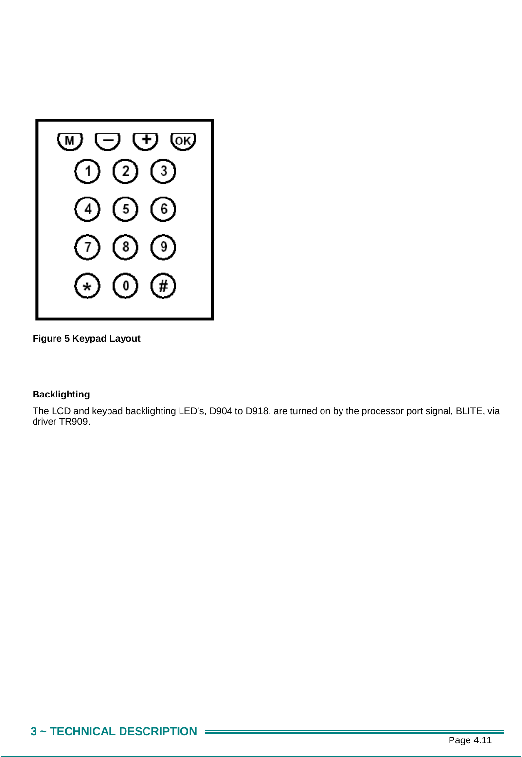
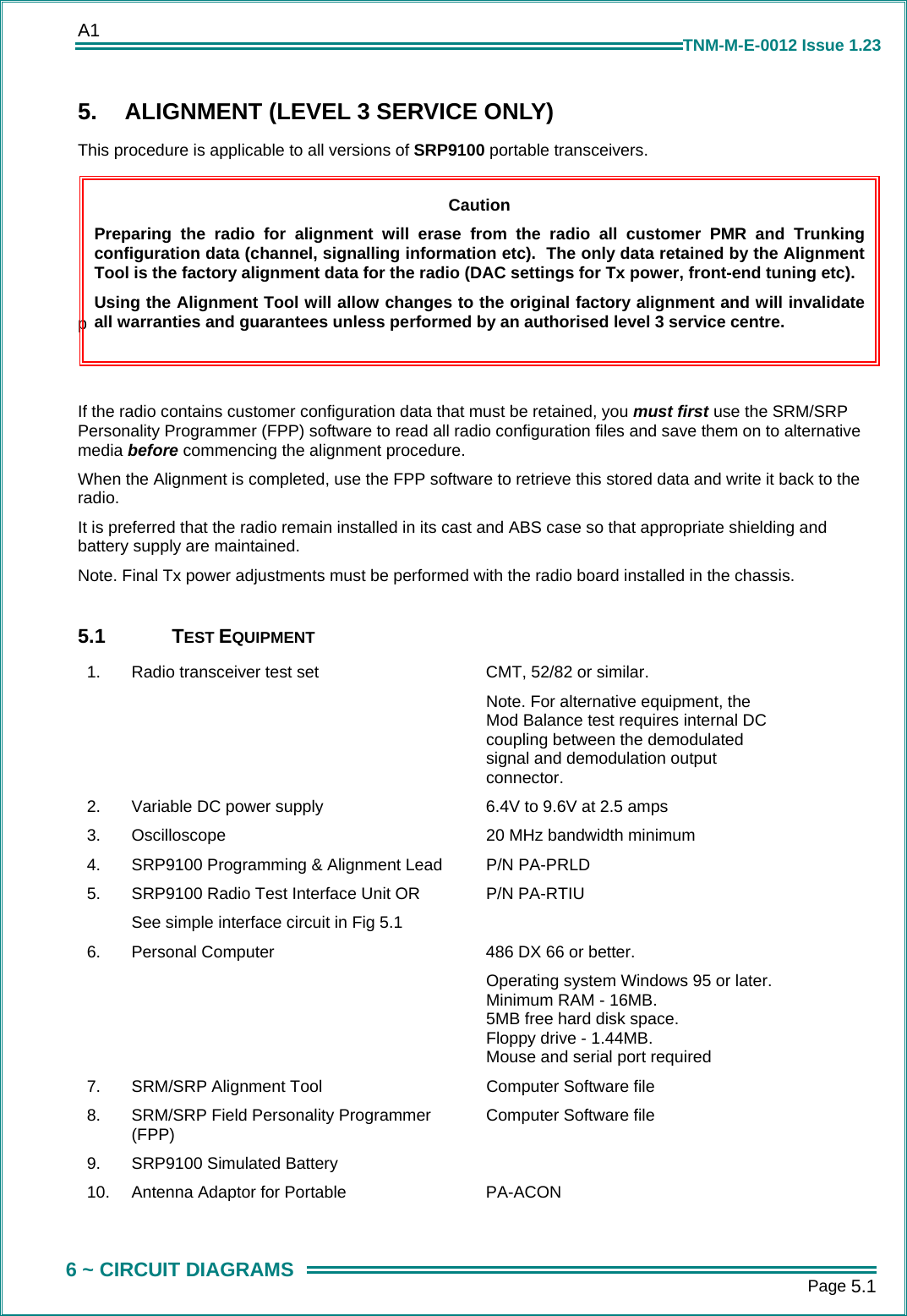
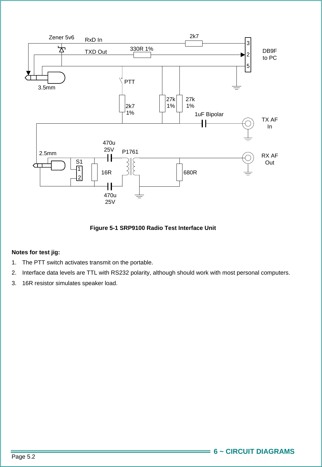
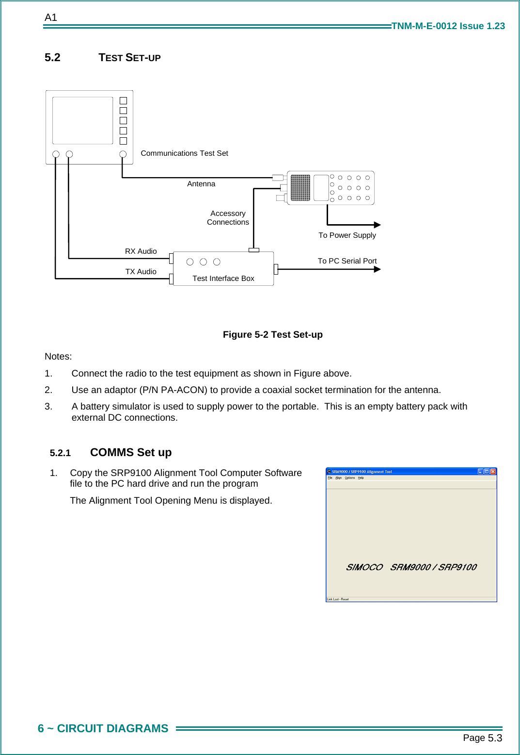
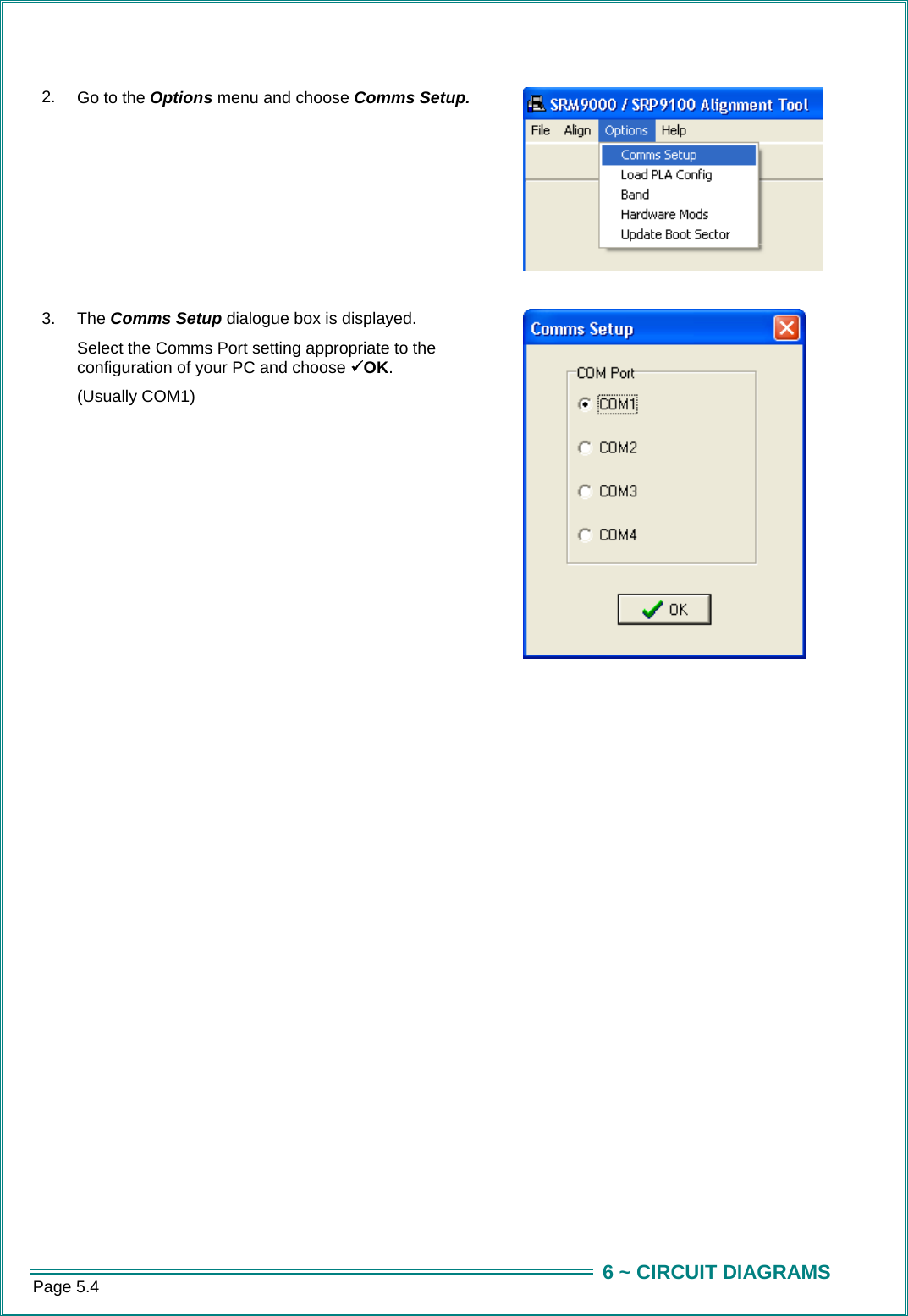
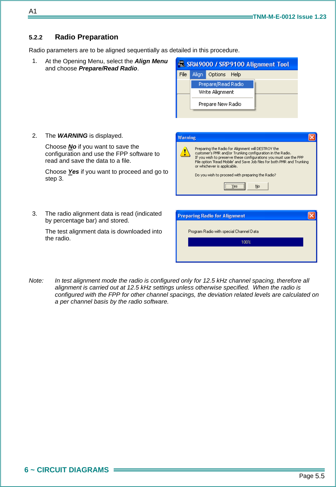
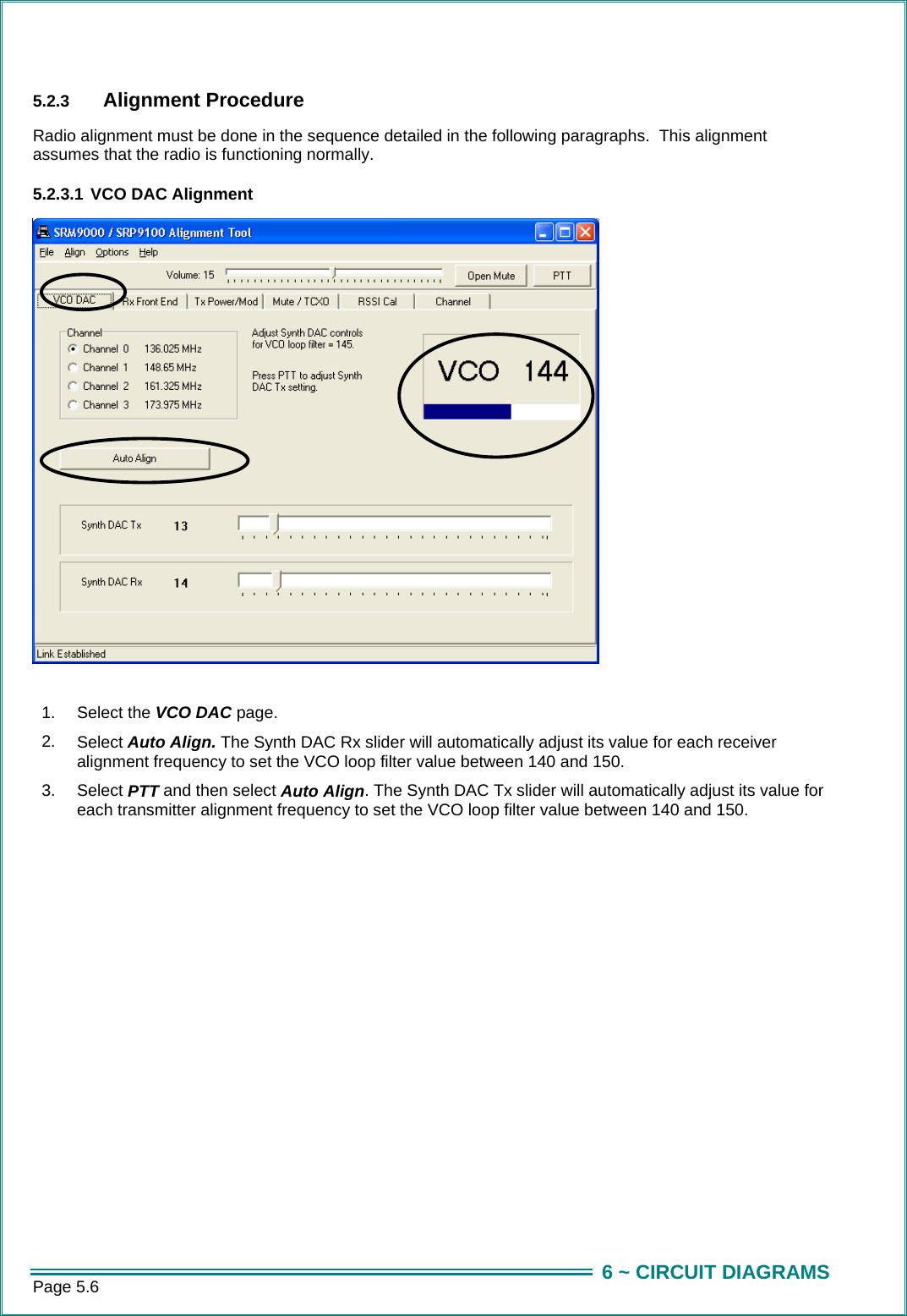
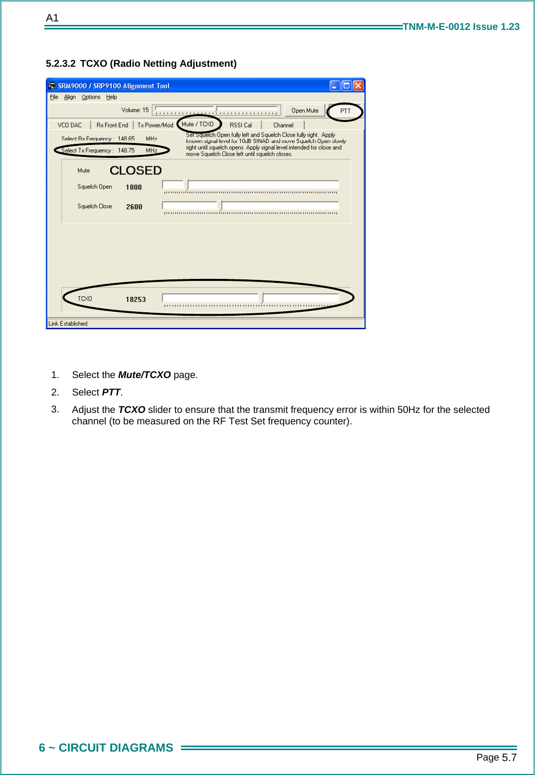
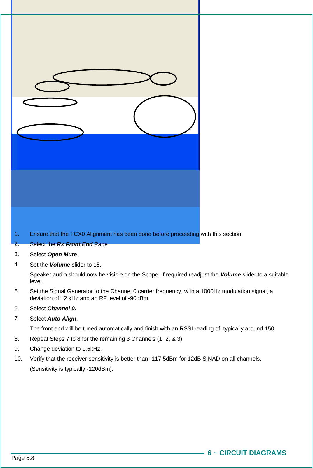
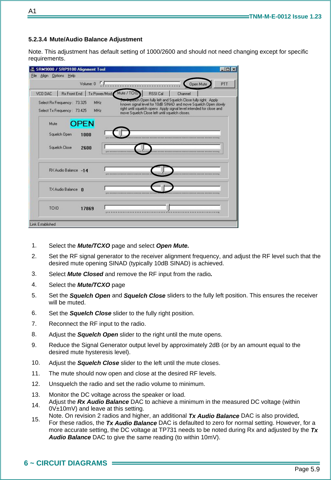
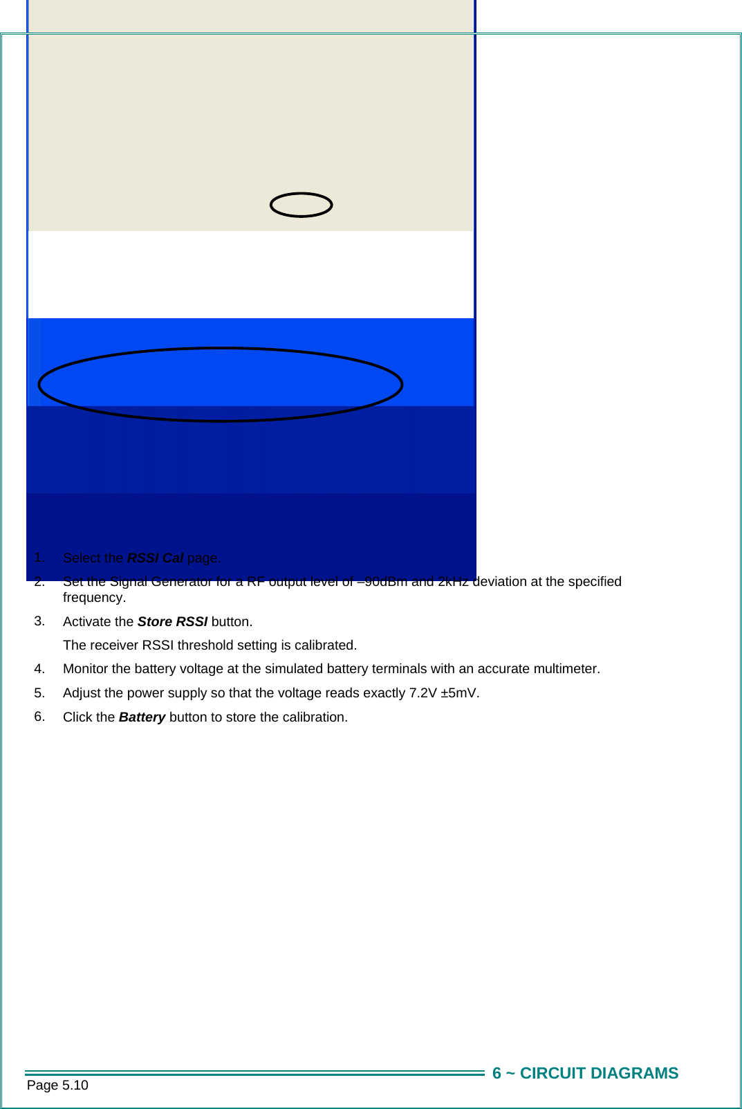
SERVICE MANUAL
2.
USERS GUIDE
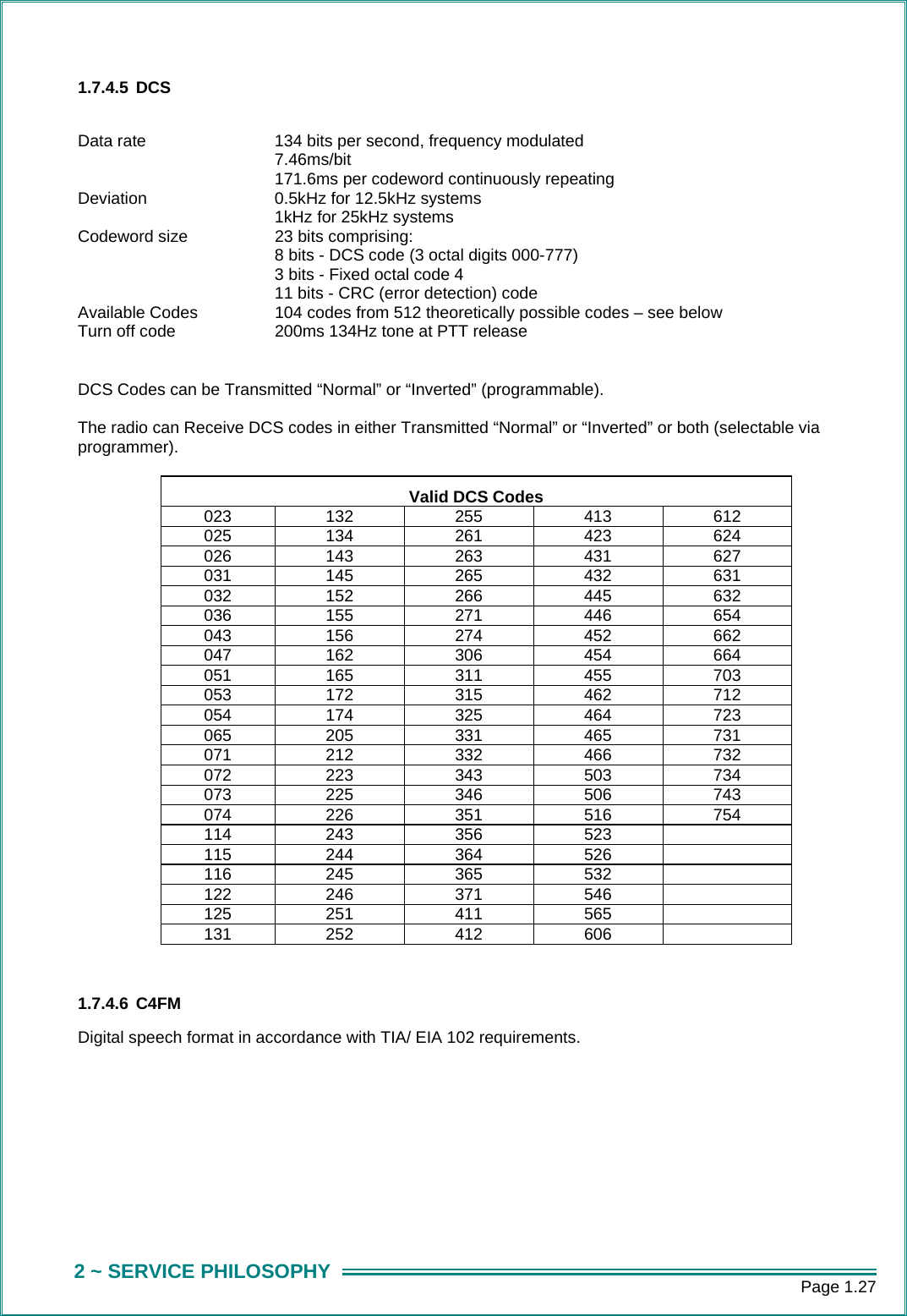
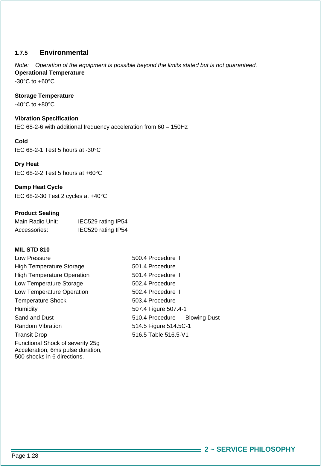
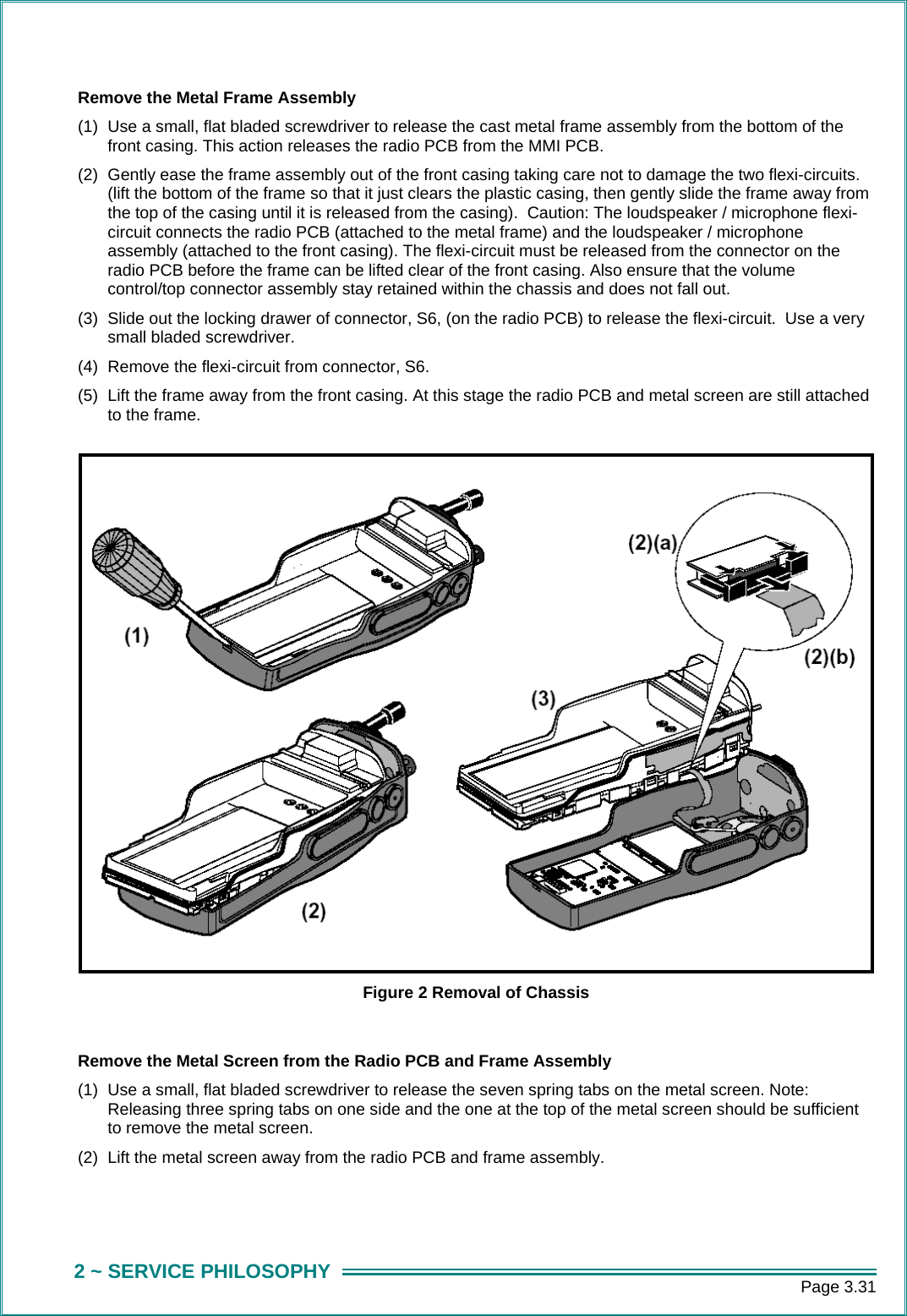
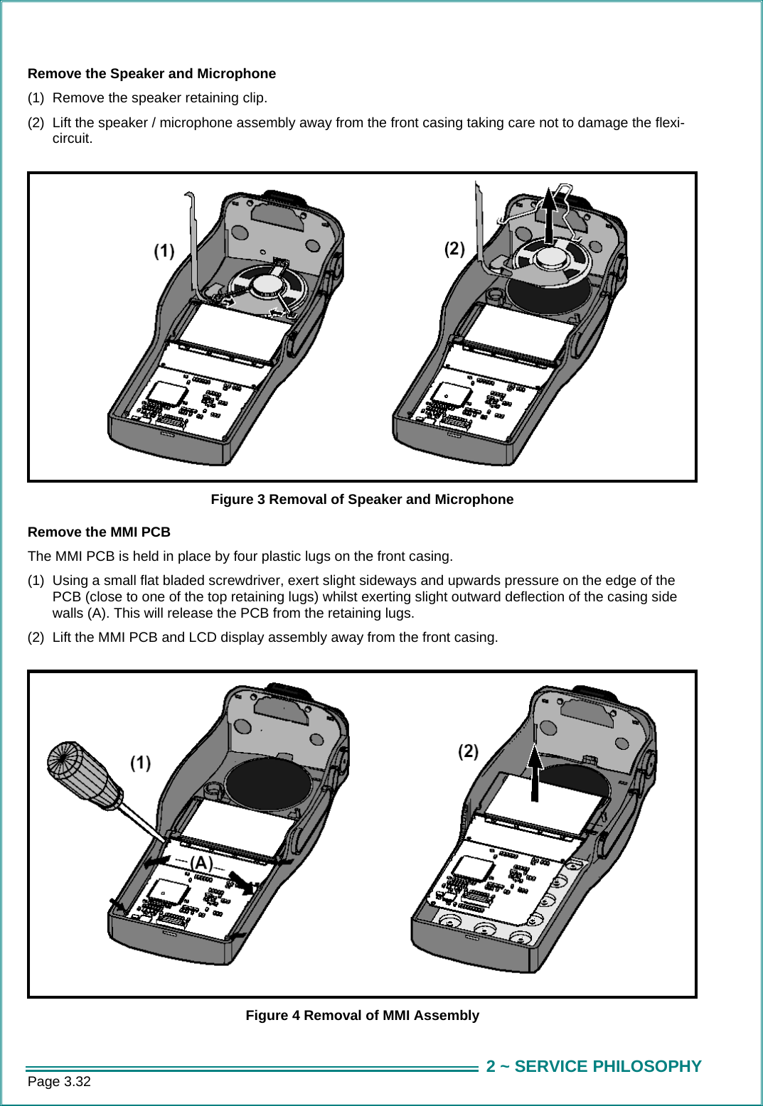
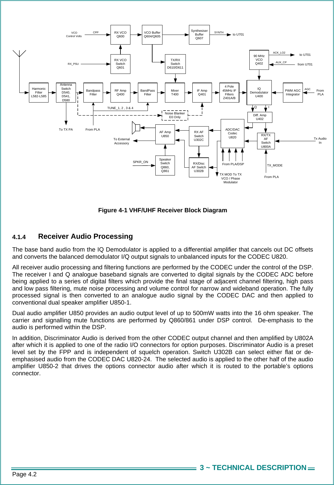
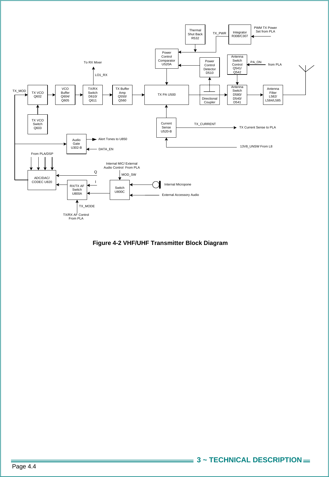
SERVICE MANUAL
Navigation menu
Upload a User Manual
Namespaces
Wiki Guide
HTML
PDF
Info
Views
User Manual
Discussion / Help
Navigation