Simoco Wireless Solutions SRP9170TU UHF PORTABLE TRANSCIEVER User Manual
Simoco Australasia Pty Ltd UHF PORTABLE TRANSCIEVER Users Manual
UserManual.wiki
>
Simoco Wireless Solutions
>
SRP9170TU User Manual
>
Users Manual
Contents
1.
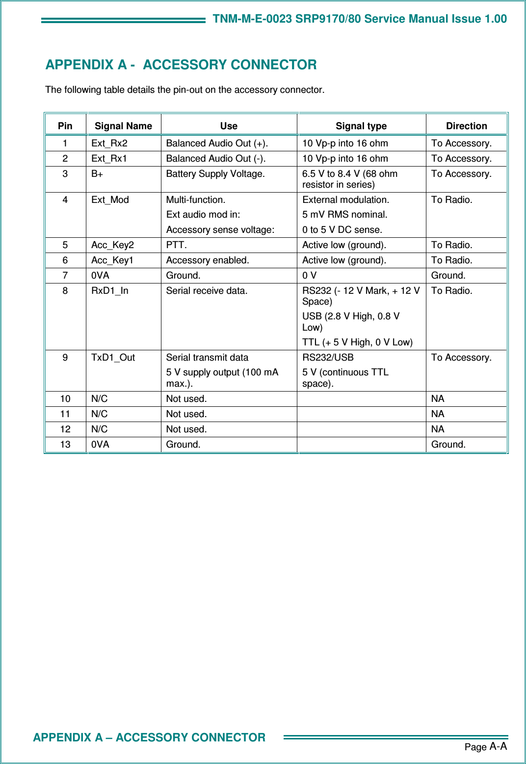
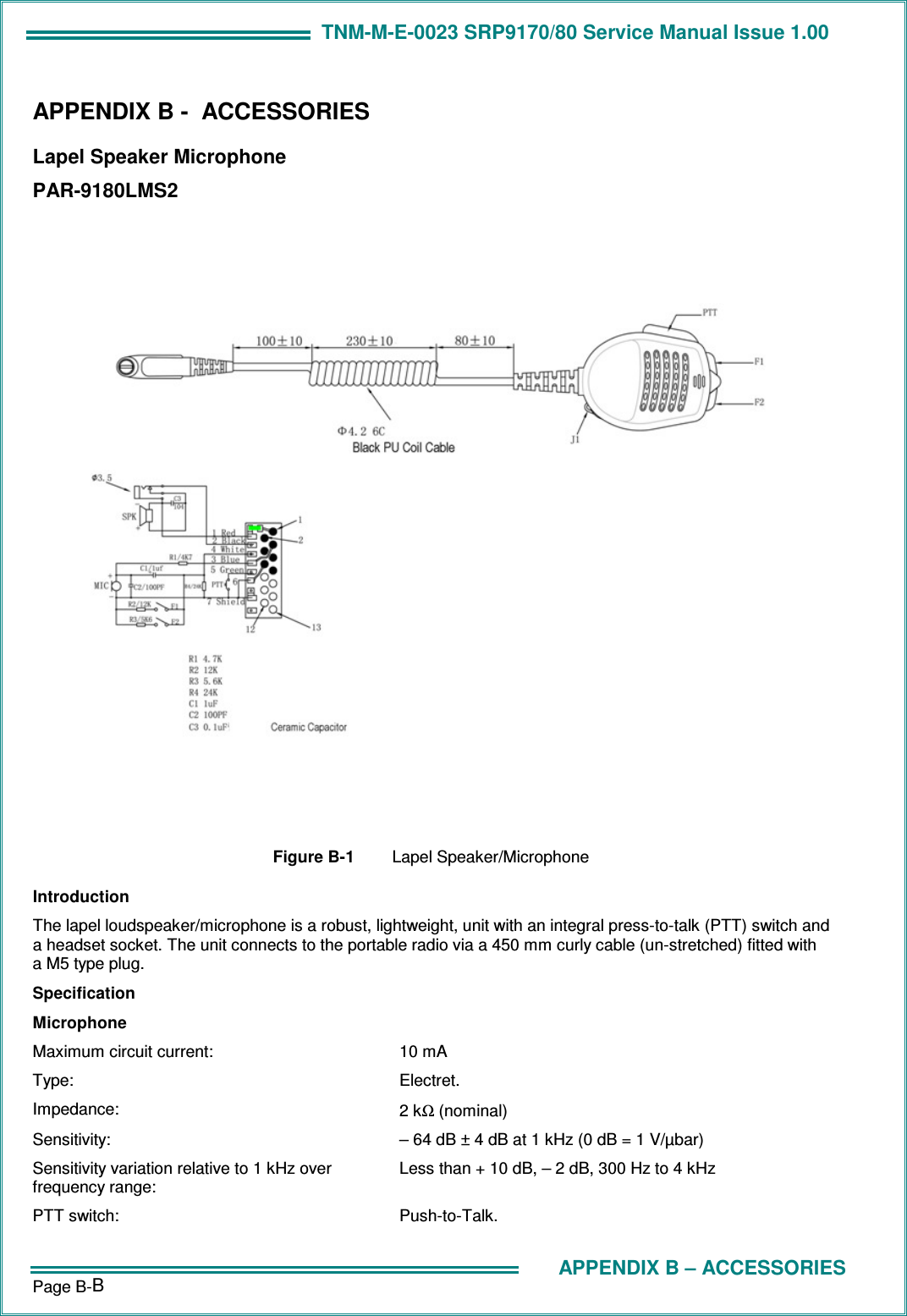
Users Manual
2.
Users Manual 2
Users Manual
Navigation menu
Upload a User Manual
Namespaces
Wiki Guide
HTML
PDF
Info
Views
User Manual
Discussion / Help
Navigation