Simoco Wireless Solutions SRP9170TU UHF PORTABLE TRANSCIEVER User Manual
Simoco Australasia Pty Ltd UHF PORTABLE TRANSCIEVER Users Manual
Contents
- 1. Users Manual
- 2. Users Manual 2
Users Manual

SRP9170/80 Series
FM VHF/UHF Portable
Radio Transceiver
SERVICE MANUAL
TNM-M-E-0023
ISSUE 1.00
Mar 2009

SRP9170/80 Series FM VHF/UHF Portable Transceiver TNM-M-E-0023 ~ Issue 1.00

TNM-M-E-0023 SRP9170/80 Service Manual Issue 1.00
Page i
Table of Contents
1.
INTRODUCTION ............................................................................................................................. 1.1
1.1
G
ENERAL
..................................................................................................................................... 1.1
1.2
S
COPE
......................................................................................................................................... 1.1
1.3
D
ESCRIPTION
............................................................................................................................... 1.1
1.4
P
RODUCT
V
ARIANTS
A
ND
F
ACILITIES
............................................................................................. 1.2
1.5
S
OFTWARE
V
ERSIONS AND
N
AMING
C
ONVENTION
.......................................................................... 1.5
1.5.1
Filename Structure............................................................................................................. 1.5
1.5.2
Application Code ................................................................................................................ 1.5
1.5.3
Software Type Code .......................................................................................................... 1.5
1.5.4
Version Number ................................................................................................................. 1.6
1.5.5
Exclusions.......................................................................................................................... 1.6
1.5.6
Displaying Software Versions ............................................................................................ 1.6
1.5.7
Automatic Version Upgrade Prompting.............................................................................. 1.7
1.5.8
Wailing Siren (Boot-up Software Corrupted)...................................................................... 1.8
1.6
A
DJUSTMENT AND
A
LIGNMENT
...................................................................................................... 1.9
1.7
S
PECIFICATION
............................................................................................................................. 1.9
1.7.1
General .............................................................................................................................. 1.9
1.7.2
Transmitter....................................................................................................................... 1.10
1.7.3
Receiver ........................................................................................................................... 1.11
1.7.4
Signalling.......................................................................................................................... 1.12
1.7.5
Environmental .................................................................................................................. 1.16
2.
SERVICE PHILOSOPHY ................................................................................................................ 2.1
2.1
S
ERVICE
C
ONCEPT
....................................................................................................................... 2.1
2.2
W
ARRANTY
.................................................................................................................................. 2.1
2.2.1
Service Within and Out Of Warranty.................................................................................. 2.1
2.2.2
Ancillary Items.................................................................................................................... 2.1
2.3
S
OFTWARE
P
OLICY
....................................................................................................................... 2.1
3.
DISASSEMBLY............................................................................................................................... 3.1
4.
TECHNICAL DESCRIPTION .......................................................................................................... 4.1
4.1
R
ECEIVER
.................................................................................................................................... 4.1
4.1.1
Front-End Filters and RF Amplifier .................................................................................... 4.1
4.1.2
First Mixer and IF Section .................................................................................................. 4.2
4.1.3
IQ Demodulator.................................................................................................................. 4.2
4.1.4
Receiver Audio Processing................................................................................................ 4.2
4.2
T
RANSMITTER
.............................................................................................................................. 4.3
4.2.1
Drivers and PA Stages....................................................................................................... 4.3
4.2.2
Power Control .................................................................................................................... 4.4
4.2.3
Antenna Switch and Harmonic Filter.................................................................................. 4.4
4.2.4
Transmitter Audio Processing............................................................................................ 4.4
4.3
P
HASE
-L
OCKED LOOP
(PLL) F
REQUENCY
S
YNTHESISER
............................................................... 4.5
4.3.1
General .............................................................................................................................. 4.5
4.3.2
Integrated Synthesiser ....................................................................................................... 4.5
4.3.3
VCOs.................................................................................................................................. 4.6
4.3.4
Negative Bias Generator and Loop Filter........................................................................... 4.6
4.3.5
Phase Modulator................................................................................................................ 4.6

TNM-M-E-0023 SRP9170/80 Service Manual Issue 1.00
Page ii
4.3.6
Reference Oscillator ...........................................................................................................4.7
4.4
S
YSTEM
C
ONTROLLER
..................................................................................................................4.7
4.4.1
DSP and PLA......................................................................................................................4.7
4.4.2
DSP Clock Oscillator ..........................................................................................................4.8
4.4.3
PLA PWM ...........................................................................................................................4.8
4.4.4
Digital I/O ............................................................................................................................4.9
4.4.5
System Memory..................................................................................................................4.9
4.4.6
Serial Data Interface.........................................................................................................4.10
4.5
P
OWER
S
UPPLIES
.......................................................................................................................4.11
4.5.1
Power On Function ...........................................................................................................4.11
4.5.2
Power Supply Detail..........................................................................................................4.12
4.6
K
EYBOARD AND
G
RAPHIC
D
ISPLAY
MMI......................................................................................4.13
4.6.1
Keypad..............................................................................................................................4.13
4.6.2
LCD Assembly Interface...................................................................................................4.13
4.6.3
MMI Interface Signals .......................................................................................................4.14
4.6.4
Function Keys ...................................................................................................................4.15
5.
ALIGNMENT (LEVEL 3 SERVICE ONLY) ......................................................................................5.1
5.1
T
EST
E
QUIPMENT
..........................................................................................................................5.1
5.2
T
EST
S
ET
-
UP
................................................................................................................................5.2
5.2.1
COMMS Set up...................................................................................................................5.3
5.2.2
Radio Preparation...............................................................................................................5.5
5.2.3
Alignment Procedure ..........................................................................................................5.6
6.
REPLACEABLE PARTS..................................................................................................................6.1
6.1
C
OMMON
P
ARTS
...........................................................................................................................6.1
6.2
A
CCESSORIES
...............................................................................................................................6.1
APPENDIX A - ACCESSORY CONNECTOR.............................................................................................. A
APPENDIX B - ACCESSORIES................................................................................................................... B
Declaration
The performance figures quoted are subject to normal manufacturing and service tolerances. The right is reserved
to alter the equipment described in this manual in the light of future technical development.
Copyright
All rights reserved. No part of this publication may be reproduced in any form or by any means without the prior
permission of TMC Radio.

TNM-M-E-0023 SRP9170/80 Service Manual Issue 1.00
Page iii
Errors and Omissions
The usefulness of this publication depends upon the accuracy and completeness of the information contained
within it. Whilst every endeavour has been made to eliminate any errors, some may still exist. It is requested that
any errors or omissions noted should be reported to:
Product Engineering
TMC Radio Pty Ltd.
1270 Ferntree Gully Road
Scoresby Victoria
3179 Australia
Ph: +61 3 9730 3800
Fax: +61 3 9730 3968
e-mail: tmcradio@tmcradio.com
http://www.tmcradio.com/

TNM-M-E-0023 SRP9170/80 Service Manual Issue 1.00
Page iv
Document History
Issue Date Comments
Draft 1.00 2009-03-31 Initial issue.
List of Associated Publications
Document No. Description Issue
TNM-U-E-0088 SRP9180 PMR Brief User Guide. 1
TNM-U-E-0089 SRP9180 PMR Operating Instructions. 1
TNM-U-E-0090 SRP9180 TMR Operating Instructions. 1
TNM-U-E-0091 SRP9180 P25 Operating Instructions. 1

TNM-M-E-0023 SRP9170/80 Service Manual Issue 1.00
Page v
Warnings and Cautions
Caution
Customer configuration files should be saved prior to any alignment adjustments.
Preparing the radio for alignment will erase from the radio all customer PMR and Trunking
configuration data (channel, signalling information etc). The only data retained by the Alignment
Tool is the factory alignment data for the radio (DAC settings for Tx power, front-end tuning etc).
WARNING
SRP9170/80 radio equipment is to be connected to TMC approved chargers and accessories only.
WARNING
Do not dispose of batteries in a fire or expose them to high temperatures.
WARNING
Do not operate your radio, without a handsfree kit, whilst driving a vehicle.
WARNING
Do not operate your radio in an explosive atmosphere. Obey the “Turn Off Two-way Radios”
signs where these are posted, eg on a petrol station forecourt.
WARNING
Servicing and upgrades of IECEx approved Intrinsically Safe radios and accessories must only
be carried out by TMC Radio Pty Ltd IECEx Intrinsically Safe trained staff, at locations that have
been IECEx approved. Please contact TMC Radio Pty Ltd for your nearest Service Department.

TNM-M-E-0023 SRP9170/80 Service Manual Issue 1.00
Page vi
IECEx Intrinsic Safety
Radio models approved for use in hazardous environments according to the IECEx scheme are marked with the
approval number XXXXXXXXX, or XXXXXXXXX.
The Intrinsically Safe protection rating for these models are either:
• (Gas) Ex iC IIB T4; and,
• (Dust) Ex tD A 22 IP67 T135
o
C; or,
• (Gas) Ex iC IIA T4; and,
• (Dust) Ex tD A 22 IP67 T135
o
C.
The following MUST be observed to maintain the IECEx protection rating:
a) use only approved Simoco battery (PAR-9180BATL2 or PAR-9180BATL3)
;
b) battery charging must only be carried out in non-hazardous areas, using an approved battery charger;
c) metal belt clips must NOT be used in hazardous areas;
d) it is a requirement that when the radio is used in a hazardous area that either the SRP9180 Accessory
Connector Cover (6102 350 1446) or an approved Simoco IECEx accessory is fitted;
e) approved accessories may only be connected and disconnected outside the hazardous areas;
f) prior to use in a hazardous area, inspect the radio and accessories for signs of damage. Any visible
signs of damage to the radio or accessories may compromise the integrity and safety of the radio. A
damaged radio or accessories must be repaired or replaced prior to use in a hazardous area;
g) incorrect storage, handling or operation of the radio and accessories, as specified in TMC Radio Pty Ltd
published User Guides and Service Manuals, may compromise the safety and integrity of the radio or
accessories;
h) approved labels stating the IECEx rating level must be affixed to the radio and accessories, and must
be legible, before their use in a hazardous area;
i) servicing and upgrades of IECEx approved Intrinsically Safe radios and accessories must only be
carried out by TMC Radio Pty Ltd IECEx Intrinsically Safe trained staff, at locations that have been
IECEx approved. Please contact TMC Radio Pty Ltd for your nearest approved Service Department;
and,
j) substitution of parts or accessories will void the equipments’ IECEx Intrinsic Safety rating.

TNM-M-E-0023 SRP9170/80 Service Manual Issue 1.00
Page vii
GLOSSARY OF TERMS
A summary of common radio terms and some other terms used in this document, and their meanings, are given
below.
3RP Trunking Signalling Specification relating to trunked networks for shared use. Used
primarily for networks in France.
ADC Analogue to Digital Converter.
AFC Automatic Frequency Control.
AGC Automatic Gain Control.
Alarm A Selcall sequence sent from subscriber equipment to indicate an Emergency situation.
When activated the radio will enter a repeating sequence consisting of an Alarm Live
Transmit Time and an Alarm Dead Receive Time.
ANN Abbreviation for Algorithmic Network Numbering. This is the numbering system where the
numbers presented to the radio user can be mapped directly to the MPT1327 PFIX /
IDENTs and vice versa by use of a fixed algorithm in combination with some other
customisation parameters. See also FPP and MEP.
ANI Automatic Number Identification.
Attack Operation
Auto Interrogate An Acknowledge identity sent as a response to an individual reset call.
Automatic Power Feature whereby the transmit power is automatically set to a level determined by the level
of the received signal. This is used to extend the battery life and/or reduce radiated
emissions.
Background Hunting The searching for an alternative and 'better' control channel whilst already on a valid
control channel.
BCAST MPT1327 broadcast message. Used to transmit information about the trunked radio
system to radio units.
BPF Band-Pass Filter.
Busy The state of a channel such that:
• for a non-signalling channel - if Busy this means that the carrier is above squelch;
• for a channel with CTCSS / DCS - if Busy this means a signal is being received
with either no CTCSS tone / DCS code or the correct CTCSS tone / DCS code;
and,
• for a channel with Selcall - if busy this means a closed channel where the signal is
above squelch.
A feature that equates to 'Do Not Disturb' such that the radio will reject all non-
emergency calls. This feature can be activated using the busy key (if assigned) or
from a menu; it is reset to disabled at switch on.
C4FM Compatible 4-Level Frequency Modulation.
Call Back A request, sent by the dispatcher, to a unit requesting that the unit calls the dispatcher
back.
CCSC Control Channel System Codeword.

TNM-M-E-0023 SRP9170/80 Service Manual Issue 1.00
Page viii
Channel Spacing The distance (in Hz) between the defined frequency channels.
CHEKKER System Interface Specification for Trunked Networks in Germany.
CLIM Call Limit Time; time limit on calls made. Normally this is defined by the Call Time Limit
parameter but can by overridden by the TSC depending upon the setting of TSCLIM.
CLIME Emergency Call Limit Timer.
Closed A state where transmit and receive are not allowed until a Selcall message to open the
channel has been received. A Closed Channel is one that defaults (when selected or after
timed reset) to its closed state. Contrast with Open. Normally a Closed channel would
have Selcall Mute and PTT Inhibit would be enabled.
CODEC COde (Analogue to Digital Converter) / DECode (Digital to Analogue Converter).
Community Repeater A communications set-up whereby different groups of radios can operate by using only
one base station. This is achieved by the use of CTCSS tone signalling such that each
group has a different CTCSS tone (encode and decode) and radios can only
communicate with other radios in their group. Only one group of radios can use the base
station at any one time.
Continuous Control Channel
A continuous control channel is one that is only used by one site. There are no breaks in
the transmission of signalling. Emergency Call Time Limit.
Control Channel A channel used for the transmission of messages that enables the TSC to control radios.
Control channels may either Continuous or Timed Shared.
Control Channel Burst A feature that enables control channel burst transmissions on systems using time-shared
control channels. It is unavailable if the control channel acquisition type is not 'Time
Shared'. To make available: go to Control Channel Acquisition Type and set to Time-
shared.
CRU Central Repair Unit.
CTCSS CTCSS stands for Continuous Tone Controlled Squelch System. A continuous tone
(lower than the audio range of the receiver) is modulated onto the carrier as well as other
signalling or voice traffic. Only receivers that have been programmed to recognise the
same CTCSS tone are able to receive the transmissions, since the squelch of receivers
looking for different CTCSS tones prevents the audio from being heard. This provides a
simple method of sending messages to selected receivers and allows several different
networks to use the same frequency. CTCSS is also known as Tone Lock or Tone
Squelch.
DAC Digital to Analogue Converter.
Dash (-) digits Digits known as 'No Tone' digits used in Selcall Identities.
DCS Digital Coded Squelch system is based on sending a continuous stream of binary code
words using low deviation, direct frequency shift keying. Only receivers which have been
programmed to recognise the same DCS sequence are able to open their squelch and
receive the associated speech transmissions. This provides a simple method of sending
messages to selected receivers only and allows several different networks to use the
same frequency. DCS is also known as CDCSS.
Decode Reception of signalling, either Selcall, where encoded tone frequencies are decoded and
identified as specific tones digits, or CTCSS/DCS, where tones are analysed to see if the
channel should be opened.
Demanded Demanded Registration; a procedure in which the TSC forces a single radio unit to
attempt registration immediately (providing the radio is not already attempting to register).

TNM-M-E-0023 SRP9170/80 Service Manual Issue 1.00
Page ix
Disabled The 'False' state of a parameter. That indicates this parameter is not active. Typically this
state is represented by an unmarked check box. Compare with Enabled.
DSP Digital Signal Processor.
DTMF Abbreviation of Dual Tone Multi-Frequency signalling. Used to dial into Telephone
networks using tone dialling.
Dual Watch A facility that enables the Radio to periodically monitor another channel for a signal above
squelch. Typically applications are checking an emergency channel whilst on another
channel.
Economiser A process by which the Receiver is powered down whilst there is no received signal.
Periodically the receiver is powered up to check for such a signal. This is used to extend
the battery life of a portable.
EDM Extended Data Message (MPT1327).
Enabled The 'True' state of a parameter that indicates this parameter is active. Typically this state
is represented by a mark (either a tick or a cross) in a check box.
Encode Transmission of signalling, either Selcall where Selcall tone digits are encoded into tone
frequencies, or CTCSS/DCS where sub-audible signals modulated onto the carrier.
ETSI European Technical Standard Institute.
Fallback A mode of operation that may be entered when the Network is suffering a malfunction.
During this mode certain facilities (e.g. PSTN) may not be available.
FFSK Fast Frequency Shift Keying. This is a signalling system for the transfer of digital
information. It works by using one of two audio tones to represent data, 1 or 0 being
transmitted.
Fleet A group of units formed such that only a shortened form of dialling (2 or 3 digits) is
required between them. These groups are normally assigned contiguous IDENTs.
FOACSU Full Off Air Call Set Up. A method of call set-up where the calling party has to manually
answer the incoming call before the trunking system will allocate a traffic channel to the
call. This reduces the loading on traffic channels as it prevents them being allocated to
calls when the called party is not present to deal with the call.
PLA Programmable Logic Array.
FPP Field Personality Programmer.
Hash (#) digits These digits are used for two purposes:
• for Selcall identities (encode and decode) - known as User Id digits. These digits are
replaced by the user id entered at switch on (if enabled); and,
• use in DTMF dialled strings - their use is network dependent to access special
services.
IDENT A 13 bit number used for Identification purposes. Associated with a Prefix (PFIX) this
forms a 20-bit address which is used for identification purposes in signalling between the
radio and the trunking system.
Identity Name given to a sequence of tones that is used in sequential tone signalling. See Valid
Selcall Digits.
Idle State The state of the radio when it is not in a call.
Inaccessible A state of a channel such that it is unavailable to the user through normal methods of
channel selection. Therefore inaccessible channels will not appear on the channel menu.
Include Calls These types of calls are used to allow a 3rd party to join into an existing call.

TNM-M-E-0023 SRP9170/80 Service Manual Issue 1.00
Page x
IS Intrinsically Safe.
LCD Liquid Crystal Display.
Link Establish Time A delay incorporated into the start of every selective call or DTMF transmission
that allows for the finite delay of the radio equipment in responding to any radio signal.
This includes both the commencement time of the originating transmitter and the
response time of the receiver.
Locked A state of a channel whereby it is not possible to change channels using the normal
up/down keys on the channel menu until the OK key is pressed. See Auto Channel
Selection Lock.
MAP27 Mobile Access Protocol for MPT1327 equipment.
MEP Miniaturisation Extent Parameter. Used in systems that use ANN numbering.
MMI Man-Machine Interface.
Modifier Part of a dialled string that modifies the nature of the call made to a number (e.g. dialling
"*9" before the number that is to be dialled will modify the call to be an emergency call).
MPT1327 A signalling standard for Trunked Private Land Mobile Radio Systems. Defined for
systems in the UK but also used outside the UK. Issued January 1988.
MPT1343 A System Interface Specification for commercial Trunking networks. Defined for systems
in the UK but also used outside the UK. Issued January 1988.
Multiax CTCSS based multi channel sharing system.
Noise Blanker A circuit designed to reduce automotive ignition interference.
NDD Network Dependent Data. This is a field within the CCSC codeword that is used by the
trunking system to identify information about the trunking network and, in particular,
information specific to the site that is radiating the control channel. It is used by the radio
when it is acquiring a control channel to identify valid channels.
Nuisance Delete
Null Id A Selcall identity that is not defined and whose tones' field is displayed as a blank.
Open A state where transmit and receive are allowed. The channel is no longer open when
reset.
Normally an Open channel would not have Selcall Mute and PTT Inhibit would be
disabled.
OPID Network Operator Identity used in Regional Systems. See Roaming.
PABX Private Automatic Branch Exchange.
Password An optional password system available on the radio. This feature is only available if the
radio does has a display and a keypad. To make available: go to Hardware Components,
Terminal Settings and set Product Type to one which has a display and a keypad.
PFIX The 7 most significant bits of an MPT1327 address number. Normally same fleet units
have same prefix. Relates to individual and group address numbers.
PiN Diode P-type intrinsic N-type diode. Type of diode used for RF switching.
PLL Phase-Locked Loop.
PMR Private Mobile Radio (not normally trunked).
Priority Channel A channel in a search group that is scanned between every other channel.

TNM-M-E-0023 SRP9170/80 Service Manual Issue 1.00
Page xi
PSTN Public Switched Telephone Network.
PTT Press To Talk. This is the term given to the operator’s key normally used to commence
transmitting a message.
PTT Inhibit A state whereby transmission using the PTT is not allowed. Also know as Tx Lockout.
PWM Pulse Width Modulation.
Queuing The storing of a Selcall Identity for later transmission.
If inhibited from transmitting a Selcall sequence because the channel is busy then the
radio can queue the Send 1 / Send 2 sequence for later transmission. When a radio unit
is in Queuing mode all incoming calls are stored automatically in a queue for later
examination. The caller is given an indication that the call has been queued by the called
party. The queue will contain the identity of the caller and the status value received (if a
status call). Up to 20 calls may be queued. The Queuing mode may be selected using the
Modes Menu.
Note: Connecting a MAP27 device to a radio that is in queuing mode will disable queuing.
All incoming calls will then be routed both to the radio user interface and to the MAP27
device connected to the radio. Also known as Logging Mode.
Reference Frequency Normally this is generated from a high stability crystal oscillator reference and is divided
digitally in a frequency synthesiser for comparison with other frequency sources, e.g. a
VCO.
Registration Registration is a technique used to ensure that the trunking system knows the location of
radio units that are using the system. This allows the system to set-up calls quickly
without having to search the whole system for the called radio.
Repeat Tone A Selcall tone that is used to replace repeated tones. Fixed at tone E.
Example: an identity entered as '12333' would be sent by the radio as '123E3'.
Reset Resetting is caused by Three Tone Reset, a Remote Reset, and an Individual reset or a
Group reset (Call Types in Decode Identity). When a radio is reset the effect on the radio
will be as follows:
• any Call Alerts will be stopped;
• the Call LED flashing will stop;
• if the channel is in Open mode then the channel is closed;
• the PTT is optionally inhibited (see PTT Inhibit After Reset Sequence);
• in searching - if paused on a Selcall channel then searching resumes; and,
• if the Acknowledge property of a Decode Identity is set to 'Auto Interrogate' or
'Transpond & Auto Interrogate' then the Auto Interrogate encode identity is
transmitted.
Roaming This is a process that allows changing between regional trunking systems which have
different Operator Identities (OPIDs). Not allowed on MPT1343 Systems.
RSSI Received Signal Strength Indicator.
Scanning Process of switching between the channels in the nominated search group in cyclic
sequence, stopping when the search condition (which may be to look for either a free or a
busy channel) is satisfied.
SDM Short Data Message.
Selcall Selective Calling - a system of signalling which allows 'dialling up' of specific mobiles,
portables and controllers. Such a system may be used to pass messages as a data
message to a specific user or group of users. It can be used to provide remote switching
facilities and to provide access control into community repeaters or similar devices.

TNM-M-E-0023 SRP9170/80 Service Manual Issue 1.00
Page xii
Selcall Mute A state of the audio gate whereby the loudspeaker is muted (closed) until a valid Selcall is
received.
Selcall System Selective Calling, uses a tone sequence at the start, and end, of a call to control which
members of a fleet react to the transmission.
SFM Short Form Memory.
Sidetone Sidetone is the audio which can be (optionally) heard when Selcall, DTMF and tone burst
transmissions are made.
Simplex Mode of operation whereby the radio operates as a conventional fixed channel radio
outside the Trunking network.
SINAD Ratio of SIgnal plus Noise And Distortion to noise and distortion expressed in dB.
Squelch System used to prevent weak, unintelligible signals and random noise from being heard
by a radio operator while still allowing intelligible signals to be received normally. This is
accomplished by the use of a threshold below which any received signals are ignored.
Only signals whose signal-to-noise ratio is above the squelch level cause the audio
circuits of the radio to be enabled, with the result that only satisfactory signals are
received. The squelch level is specified in SINAD.
Star (*) digits Digits known as Status or Message digits. These digits are used for three purposes:
• Status Digits for Selcall Identities;
• Wildcard digits in Status strings; and,
• use in DTMF dialled strings - their use is network dependent to access special
services.
Status A feature whereby a radio's status (or usually the status of the radio's user) can be
transmitted and a status message from other radios can be displayed. This operates
through status digits in Selcall identities, either in Encode Identities or Decode Identities
as follows:
Encode Identities: status digits within the identity are used to transmit the current
situation of the radio's user (e.g. "Out To Lunch"); and,
Decode Identities: status digits are looked up in a table (Status Menu) for possible
messages to display.
SW Software.
SYS System Identity Code part of the CCSC.
TCXO Temperature Compensated Crystal Oscillator.
Temporary Temporary Registration; a process carried out by the Dispatcher due to some system
failure that prevents it from carrying out normal registration. The radios will recognise this
temporary registration mode but will otherwise use the network in the same way as if they
were registered. They may be required to re-register when normal registration mode is
resumed.
Three Tone Reset This is a system whereby a call to a user automatically reset all other users in a group.
Example: a call to user '12345' would call 12345 and reset all other users on this channel
with an identity 123nn where n can be any digit 0-9, A-F.
Timed Reset Facility that causes the Radio, after a certain period of time, to restore current channel to
its initial condition e.g. if it was previously searching it will resume searching.
Time Shared A time-shared control channel is one that is used by more than one site. This allows a
wide coverage area to be obtained using only one frequency.

TNM-M-E-0023 SRP9170/80 Service Manual Issue 1.00
Page xiii
The forward channel from the TSC to the radio is divided into timeslots. Each site using
the channel is allocated one timeslot in which to transmit and send signalling.
Therefore, when on a timeshared channel, the radio may be able to receive bursts of
signalling from different sites at different signal strengths and may receive periods when
no signalling is received.
Depending on the type of system, the radio may be able to perform transactions with any
site it can receive from or only with a specific site.
TMR Trunked Mobile Radio.
Tone Burst An audio tone is transmitted at the start of transmission to inform a relay (repeater)
station to switch itself on to relay the transmission.
Transpond An Acknowledge identity sent as a response to an individual call.
TRAXYS Air Interface for the PTT Telecom Trunked Radio Network, used in the Netherlands.
TSC Trunking Site Controller. Central control required for the Trunking System to function.
Controls base stations.
Tx Inhibit A facility which prevents the user from transmitting (other than alarms), while the channel
is Busy.
UMP User Memory Plug. A special device that contains the customisation data for the radio. If
this is removed then this can cause the radio to behave in a number of ways.
User Defined Groups These groups are set up by the user (contrast with Dynamic User Groups) when the user
desires to be included, temporarily, in an existing group. Up to 8 groups may be defined
(in addition to the Network group Idents defined by Network Group Numbers). This
feature is only available if User Defined Groups parameter is enabled. These temporary
groups are lost at switch off unless 'Save Groups at Switch Off' is enabled.
User Identity This is a sequence of up to four digits entered by the user when the Radio is switched on,
if this option is programmed. These digits are then substituted into any transmitted Selcall
identity which includes # digits.
VCO Voltage-Controlled Oscillator.
Vote Method used to compare the signal strength on a current channel with another specified
channel and then to choose the channel having the stronger signal.
Voting Feature used during searching when there is more than one channel that satisfies the
required conditions. It involves examining all the channels that satisfy the required
conditions, and then selecting the channel with the highest signal strength.
VOX Voice Operated Transmit.

TNM-M-E-0023 SRP9170/80 Service Manual Issue 1.00
Page
1.1
1 - INTRODUCTION
1. INTRODUCTION
1.1 G
ENERAL
The SRP9170/80 series of FM portable radio transceivers are designed for conventional PMR and Trunked
operation in VHF and UHF radio systems.
The transceiver is available in four functional variants. The variants are as follows:
Description PMR/Trunked
Portable Transceiver with no Keypad and Graphic Display. SRP9170
Portable Transceiver with no Keypad and Graphic Display, Intrinsically Safe. SRP9170is
Portable Transceiver with Keypad and Graphic Display. SRP9180
Portable Transceiver with Keypad and Graphic Display, Intrinsically Safe. SRP9180is
1.2 S
COPE
This manual provides technical specifications, description and servicing details for the SRP9170/80 series of
portable radio transceivers together with the related accessories.
Unless specifically stated otherwise, the text and illustrations refer to all versions in the series.
1.3 D
ESCRIPTION
The design concept utilises wide band analogue techniques for RF transmit and receive circuitry with digital signal
processing of analogue or digital modulation and demodulation. Electronic tuning is used throughout the portable to
eliminate manual tuning and level adjustment.
A Digital Signal Processor (DSP) and a Programmable Logic Array (PLA) are used with other dedicated devices in
the SRP9170/80 to perform the following functions under software control:
• frequency synthesis of all operating frequencies;
• modulation and demodulation of 10 / 12.5 / 20 / 25 kHz FM signals on a per channel basis;
• modem functionality for specified data modulation schemes;
• filtering, pre-emphasis, de-emphasis, limiting, compression, muting, CTCSS, Selcall or any other
frequency or level dependent signal modification;
• serial communications with the Control Ancillaries, Field Programmer and Alignment Tool; and,
• tuning control data for Tx and Rx.
The SRP9170/80 Transceiver comprises a rugged cast internal lightweight alloy chassis that houses two printed
circuit board assemblies and provides all heatsink requirements. The battery clips into the chassis where it is
securely locked via a tensioned clip. Release is achieved by sliding the latch towards the bottom of the transceiver.
The chassis is enclosed in a high impact polycarbonate ABS plastic case that retains the speaker, keypad and
display.
Gaskets fitted around keys, the display, buttons, connectors, switches, and the antenna socket provide a seal
against moisture and dust ingress.
The main PCB assembly comprises a multi-layer board containing all the RF and control circuitry. The display or
man-machine interface (MMI) board is connected via a miniature connector to the main board. Flexible PCBs
connect the speaker and microphone, accessories connector, volume control and channel / zone switch to the main
PCB. Provision is made in the radio for optional plug-in accessories (i.e. for encryption, P25, etc).
The standard battery capacity is 2200 mAh and utilises lithium-ion technology to suit the endurance requirement of
the portable application.
The antenna is connected to the radio via an SMA plug that is mounted in the radio chassis. The antenna flange
provides it with additional rigidity when seated on the radio body.

TNM-M-E-0023 SRP9170/80 Service Manual Issue 1.00
Page 1.2
1
-
INTRODUCTION
1.4 P
RODUCT
V
ARIANTS
A
ND
F
ACILITIES
Product variants and facilities are detailed in Table 1-1, Table 1-2 and Table 1-3.
Table 1-1 Common Features for All Variants
Model
Feature 9170 / 9170is 9180 / 9180is
Keys 7 Function keys. All keys
can be customised.
7 Function keys. All keys
can be customised.
Keypad Non keypad. 12 button numeric keypad.
Display LCD 12 character with bit
mapped section and fixed
icons.
Graphic LCD 102 x 64
pixels.
Volume Rotary control. Rotary control.
Zone Rotary control – 3 position. Rotary control – 3 position.
Channel Rotary control – 16 position. Rotary control – 16 position.
Indicators Tri-colour LEDs. Tri-colour LEDs.
Facility connector Yes. Yes.
Frequency Bands* 66 to 88 MHz, 136 to 174 MHz, 335 to 400 MHz,
400 to 480 MHz, 440 to 520 MHz.
Channel Spacing*
10
#
/ 12.5 / 20 / 25 kHz.
Menu driven Yes (limited selections). Yes.
Customisable Menus Yes. Yes.
* Not all combinations are valid or currently available.
#
Requires special hardware build (narrow band filters).

TNM-M-E-0023 SRP9170/80 Service Manual Issue 1.00
Page
1.3
1 - INTRODUCTION
Table 1-2 Conventional-PMR Variants
Model
Feature 9170 / 9170is 9180 / 9180is
Channels
200 (nominal). 1000.
Signalling
CTCSS / DCS Selcall / FFSK / DTMF. CTCSS / DCS / Selcall / FFSK / DTMF.
Text Messaging
FFSK text messaging display.
Selcall status messaging.
FFSK text messaging display.
Selcall status messaging.
Attack Operation:
Yes. Yes.
DTMF Encode
Pre-defined Encodes via function keys. Pre-defined Encodes via function keys.
Free form encodes via keypad.
PTT Limit Timer with
warning beeps
Yes. Yes.
PTT Inhibit on Busy
Yes. Yes.
Scanning
100 groups with up to 15 channels per
group.
240 groups with up to 15 channels per group.
4 user defined scan groups.
Voting
Up to 50 groups consisting of up to 16
channels per group.
Up to 200 groups consisting of up to 16
channels per group.
Priority Scanning
Yes. Yes.
Nuisance Delete
- Yes.
Multiax
Yes. Yes.
Phonebook
250 entries. 250 entries.
P25
Optional. Optional.

TNM-M-E-0023 SRP9170/80 Service Manual Issue 1.00
Page 1.4
1
-
INTRODUCTION
Table 1-3 Analogue Trunked Variants
Feature 9170 / 9170is 9180 / 9180is
Channels
1024 channels in 50 sub-bands.
Frequency Bands
136 to 174 MHz, 400 to 480 MHz.
Background Hunt and
Vote-Now
Yes. Yes.
MPT1343 dial strings
Yes. Yes.
ANN Numbering
Yes. Yes.
Phonebook Memories
250. 250.
User Phonebook
Recall entries configured by FPP only. Recall and edit.
Alpha Status List
Yes. Yes.
SDM / EDMs
Yes. Yes.
NPDs
Yes. Yes.
Attack Operation
Yes. Yes.

TNM-M-E-0023 SRP9170/80 Service Manual Issue 1.00
Page
1.5
1 - INTRODUCTION
1.5 S
OFTWARE
V
ERSIONS AND
N
AMING
C
ONVENTION
There are various associated items of software (SW) required for the SRP9170/80 radio and programmer to
operate. This section simply defines the naming rules of the SW files to allow identification and conformity.
This allows different versions of SW to be distributed and co-exist without confusion.
The SRP9170/80 Transceiver has three items of SW for digital and analogue PMR, Trunking and Alignment.
1.5.1
Filename Structure
• 2 character Application code.
• 2 or 3 character SW Type code.
• 3 character version number.
• File Extension as required.
eg b1tm182.bin (trunking).
b1p_182.bin (PMR).
b1s_182.bin (startup).
1.5.2
Application Code
This identifies the application the SW was initially designed for:
b1 Standard SRP9170/80 Software.
1.5.3
Software Type Code
This identifies different types of SW within an application:
s_ Start-up code (for alignment and start-up);
p_ Conventional PMR code;
p_s Scrambler;
tm Trunk MPT;
ta Trunk ANN;
bo Transceiver Boot-code;
bc Transceiver Boot-Backup-code;
bf Transceiver PLA-code; and,
ba Transceiver PLA-Backup-code.
Note the above file names are not stored within the code. As a consequence, when the radio is read by the FPP,
the FPP will display version numbers and release dates for the Backup, Startup, PMR, and TMR codes. The
Bootloader, PLA Backup and PLA codes show release dates only.
TNM-M-E-0023 SRP9170/80 Service Manual Issue 1.00
Page 1.6
1
-
INTRODUCTION
1.5.4
Version Number
This is a 3-digit number allocated by Engineering to identify the SW version:
eg 182 = Version 1.82.
1.5.5
Exclusions
The Programmer SW does not follow the above rules, as it is a PC based Program and its version number can be
easily identified by starting the SW. Later releases of SW will be backward compatible, unless deliberately not so, in
which case a different directory structure/path may be implemented.
1.5.6
Displaying Software Versions
Each Transceiver SW code file (eg b1tm182.bin, etc) contains version information about itself and possibly
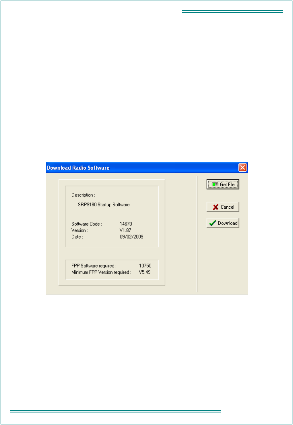
compatible Programming SW.
For Radio SW saved on Disk, this information can be displayed via the Programmer function:
Options: Upgrade_Software: Get_File
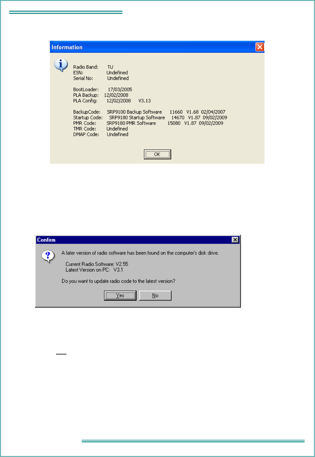
For Software loaded in the radio, information can be read from the Transceiver and displayed via the
Programmer function:
TNM-M-E-0023 SRP9170/80 Service Manual Issue 1.00
Page
1.7
1 - INTRODUCTION
Options: Radio_Information
The portable software version can be read from the portable display if required by accessing the Set-up menu and
then choosing Radio Info and selecting the software version on the radio.
1.5.7
Automatic Version Upgrade Prompting
When a configuration is downloaded to the Transceiver, the Programmer performs a check on the SW currently
installed in the radio. If a later version of SW exists (on PC hard disk) then the Programmer will prompt the user
with the following message:
Note: as early versions of FPP cannot recognise a more recent revision of the radio, it is important that the latest
FPP version is downloaded from: http://www.tmcradio.com.
If YES is selected, the Transceiver Radio code is updated before the new configuration is downloaded.
If NO is selected, only the configuration is downloaded.
It is strongly recommended to select “Yes” when this message is shown.
This process also updates the Start-up code to ensure it is compatible with the loaded PMR or Trunk code.
Note: if the …\StandardFPP\RadioSW folder contains no files, then the above check will not be performed.

TNM-M-E-0023 SRP9170/80 Service Manual Issue 1.00
Page 1.8
1
-
INTRODUCTION
1.5.7.1 Transceiver SW Description, Start-up and Backup-Software
The SRP9170/80 Transceiver software is split into the following separate modules:
• Bootloader and Backup Software;
• Start-Up Software;
• PLA and PLA-Backup Software;
• Mainline PMR Software;
• Mainline Analogue Trunk Software; and,
• P25 Software.
When the Transceiver starts, it basically performs the following steps:
• Initial execution starts with the Bootloader code, which attempts to load the Start-Up Software (if Start-Up
checksum is bad, then the Backup Software is loaded);
• Start-Up Software then downloads the PLA code (or PLA-Backup code if PLA checksum is bad) to the
PLA device. If both PLA and PLA-Backup checksums are bad then the radio is not operational and serial
communication is not possible;
• Start-Up Software then reads the On/Off switch line and compares this with saved parameters to
determine if the radio should continue to power-up or switch itself off again; and,
• Start-Up Software then attempts to load either Mainline PMR or Analogue Trunk Software (dependent on
saved parameter) and switches execution to complete the power-up process and start normal operation.
If the Mainline Software cannot be loaded, or a Job file configuration has not been loaded (eg non-existent or
checksum fail) then execution switches to Backup Software until the error is corrected (eg by FPPing the radio).
There are three states that the radio can end up in after switch-on:
• Mainline Analogue Trunk Software or Mainline PMR Software (normal power-up).
If the radio does not have a valid Job file configuration loaded, then it will display a “No PMR Cfg” or “No
TMR Cfg” message;
• Start-Up Software (characterised by “Alignment Mode” shown on the display). This is also the code that
is running when the radio is being aligned using the Alignment Tool; and,
• Backup Software (via various paths from above).
1.5.8
Wailing Siren (Boot-up Software Corrupted)
A “WAILING SIREN” sound is emitted from the Loudspeaker while the radio is running in Boot Backup Software. In
this mode the FPP can be used to re-load a Job file, or re-load Start-Up or Mainline Operating Software.
Simply writing a Job file to the radio should allow the FPP to determine and update the offending software –
however there may be instances where the FPP cannot determine this and the Start-Up and Mainline Software
should be updated manually. This can be done using the FPP: Upgrade_Software: Get_File … then Download.
Both Start-Up Software (filename = b1s_xxx.bin) and Mainline PMR (b1p_xxx.bin) or Trunk (b1txxxx.bin) should be
loaded if the FPP cannot automatically fix the problem. The wailing siren should stop once the problem is fixed.
Note 1: holding down the alarm key (F7) and PTT key when power is applied to the radio will also force the radio to
start-up in Backup Software. This may be useful in some situations.
Note 2: should these steps fail to restore the radio and stop the Wailing Siren, the radio will need to be returned to a
Level 3 Service Centre for FLASH replacement.
TNM-M-E-0023 SRP9170/80 Service Manual Issue 1.00
Page
1.9
1 - INTRODUCTION
1.6 A
DJUSTMENT AND
A
LIGNMENT
There are no internal adjustments in the SRP9170/80. Re-programming and alignment are performed using
software tools. For testing, a special test jig is required so to provide power and control lines.
As the radio has no internal adjustments, there is no need to have the radio PCBs powered while out of the chassis.
Field repair of the PCBs is not recommended as specialised equipment is required to fault find and repair the
boards.
1.7 S
PECIFICATION
1.7.1
General
Operation:
Single or two-frequency simplex (half-duplex).
Modulation:
Frequency modulation (phase) F3E, F1D, F1E.
Battery Voltage:
7.2 V DC (nominal).
Current Consumption:
All measurements at 7.2 V
Radio off: < 120 uA
Standby (squelched): < 120 mA
Rx Audio O/P = 500 mW: < 340 mA
Transmit: Freq Range
(MHz)
Tx Power 1 W
(A)
Tx Power 5 W
(A)
66 to 88 < 0.7 < 1.8
136 to 174 < 0.8 < 2.2
174 to 400 < 1.0 < 2.2
400 to 520 < 1.0 < 2.5
Frequency Bands:
Band Freq Range (MHz)
E0 66 to 88
AC 136 to 174
R3 335 to 400
TU 400 to 480
UW 440 to 520
Switching Bandwidth:
Radio covers the complete band without retuning.
Channel Spacing:
10
#
/ 12.5 / 20 / 25 kHz
#
Requires special hardware build (narrow band filters).
Frequency Stability (-30 °C to 60 °C)
Less than ± 1.5 ppm

TNM-M-E-0023 SRP9170/80 Service Manual Issue 1.00
Page 1.10
1
-
INTRODUCTION
Dimensions (radio excluding antenna): Height Width Depth
150 mm
Excluding
volume and
channel/zone
control.
63 mm 37 mm
Including 2200 mAh
battery.
Weight:
Radio only 210 g
Battery Li-ion 2200 mAh 250 g
Antenna E0 30 g
Antenna UW 19 g
Battery Endurance: > 10 hours, high transmit power, 2200 mAh battery, 90:5:5 duty
cycle.
Conformance Approvals:
ETSI EN 300 086*
EN 300 113*
EN 300 489*
EN 300 219*
Australia AS/NZS4295*
* Pending in some cases.
1.7.2
Transmitter
Power Output: Any three levels programmable from:
High Power: 5 W Adjustable down to 0.5 W.
Low Power: 0.5 W Adjustable up to 5 W.
Transmitter Rise Time: Less than 40 ms.
Duty Cycle: 1 minute transmit: 4 minutes receive.
Spurious Emissions: < 0.25 µW (9 kHz to 1 GHz)
< 1.0 µW (1 GHz to 4 GHz)
Residual Noise: 60 % deviation, CCITT Weighted:
25 kHz Channel Spacing > 45 dB
12.5 kHz Channel Spacing > 40 dB
Audio Frequency Distortion: ≤ 3 % (at 60 % deviation)
Audio Frequency Response: 300 to 3000 Hz* + 1 dB / - 3 dB
Figures apply for a flat audio response or a 6 dB/octave
pre-emphasis curve.
(* 2550 Hz for 12.5 kHz channel spacing).
Audio Sensitivity:
(PMR Mode 1 kHz, user
programmable via FPP).
Accessory Connector: 5 mV ± 2 dB
Internal Mic: 10 mV ± 2 dB

TNM-M-E-0023 SRP9170/80 Service Manual Issue 1.00
Page
1.11
1 - INTRODUCTION
1.7.3
Receiver
ETSI AS/NZS4295
Sensitivity: ≤ 0.5 µV PD (- 113 dBm) for 20 dB
SINAD
≤ 0.3 µV PD (- 117.5 dBm) for 12dB
SINAD
Adjacent Channel
Selectivity:
25 kHz Channel Spacing: > 73 dB
12.5 kHz Channel Spacing: > 60 dB
25 kHz Channel Spacing: > 73 dB
12.5 kHz Channel Spacing: > 65 dB
Intermodulation Rejection: > 65 dB > 70 dB
Spurious Response
Rejection:
> 70 dB > 70 dB
Blocking: > 95 dB > 95 dB
Conducted Spurious
Emissions:
< 2 nW (- 57 dBm) 9 kHz to 1 GHz
< 20 nW (- 47 dBm) 1 GHz to 4 GHz
< 22 nW (- 57 dBm) 9 kHz to 1 GHz
< 20 nW (- 47 dBm) 1 GHz to 4 GHz
GENERAL
FM Residual Noise
(CCITT weighted):
25 kHz Channel Spacing > 45 dB
12.5 kHz Channel Spacing > 40 dB
Mute Range: Typically 6 dB to 25 dB SINAD.
Typical setting 10 dB to 12 dB SINAD.
Mute Response Time: < 30 ms (no CTCSS).
Add 200 ms for CTCSS.
Voting Response Time: Searches at 50 ms / channel.
Audio Distortion: < 5 % for 500 mW into 16 Ω
Audio Frequency
Response: 300 to 3000 Hz*: + 1 dB to – 3 dB
Figures apply for a flat audio response or a 6 dB / octave de-emphasis curve.
(* 2550 Hz for 12.5 kHz channel spacing).
Deviation Sensitivity:
(for rated audio at 1 kHz). 20 % MSD ± 3 dB

TNM-M-E-0023 SRP9170/80 Service Manual Issue 1.00
Page 1.12
1
-
INTRODUCTION
1.7.4
Signalling
1.7.4.1 CTCSS
All 38 standard CTCSS Tones are supported as per the table below.
Identifier Frequency (Hz) Identifier Frequency (Hz) Identifier Frequency (Hz)
Q 67.0 C 107.2 0 167.9
R 71.9 L 110.9 1 173.8
S 74.4 D 114.8 2 179.9
T 77.0 M 118.8 3 186.2
U 79.7 E 123.0 4 192.8
I 82.5 N 127.3 5 203.5
V 85.4 F 131.8 6 210.7
A 88.5 O 136.5 7 218.1
W 91.5 G 141.3 8 225.7
J 94.8 P 146.2 9 223.6
= 97.4 H 151.4 * 241.8
B 100 X 156.7 # 250.3
K 103.5 Y 162.2 ‘ ‘ NONE
150.0 171.3 199.5
206.5 177.3 229.1
69.3 183.5 254.1
159.8 189.9
165.5 196.6
Encoder
Tone Deviation:
25 kHz channel spacing: 500 to 750 Hz
20 kHz channel spacing: 400 to 600 Hz
12.5 kHz channel spacing: 250 to 375 Hz
Tone Distortion: Less than 5.0 %
Frequency Error: Less than ± 0.3 %

TNM-M-E-0023 SRP9170/80 Service Manual Issue 1.00
Page
1.13
1 - INTRODUCTION
Decoder
Bandwidth: Not greater than ± 3.0 %
Deviation Sensitivity: Less than 6.0 % of system deviation (for decode with full RF quieting).
Noise Immunity: Less than 500 ms dropout per minute at 10 dB SINAD.
(CTCSS tone deviation 10 % of system deviation. RF deviation 60 % at 1000 Hz).
False Decode Rate: Less than 5 false decodes per minute (no carrier input).
Talk-off: For no dropouts in one minute, interfering tone at 90 % of system deviation
(CTCSS tone at 10% of system deviation).
Full quieting signal: 310 Hz to 3000 Hz
20 dB SINAD RF signal: 320 Hz to 3000 Hz
12 dB SINAD RF signal: 350 Hz to 3000 Hz
Response Time: Less than 250 ms (full quieting/tone > 100 Hz).
Less than 350 ms (full quieting/tone < 100 Hz).
De-Response Time: Less than 250 ms.
Reverse Tone Burst: Programmable.
1.7.4.2 FFSK
1200 Baud: 1200 / 1800 Hz MPT1317 based.
2400 Baud: 1200 / 2400 Hz MPT1317 based.
1.7.4.3 Selcall
The following tone sets are supported as per tables below:
• ST-500: CCIR, EEA, ZVEI, DZVEI, EIA.
• ST500/CML: ZVEI_3, DZVEI.
• CML: CCIR, EEA, ZVEI.
• SIGTEC: CCIR, CCIRH, EEA, ZVEI_1, XVEI_2, ZVEI_3, NATEL, EIA.
• SEPAC: CCIR, EEA, ZVEI_1, ZVEI_2, ZVEI_3, EIA.

TNM-M-E-0023 SRP9170/80 Service Manual Issue 1.00
Page 1.14
1
-
INTRODUCTION
Selcall Tone Frequency Table
(Frequency in Hz).
Tone CML ST500 SIGTEC SIGTEC SEPAC CML ST500 SIGTEC
CCIR CCIR CCIR CCIRH CCIR EEA EEA EEA
0 1981 1981 1981 1981 1981 1981 1981 1981
1 1124 1124 1124 1124 1124 1124 1124 1124
2 1197 1197 1197 1197 1197 1197 1197 1197
3 1275 1275 1275 1275 1275 1275 1275 1275
4 1358 1358 1358 1358 1358 1358 1358 1358
5 1446 1446 1446 1446 1446 1446 1446 1446
6 1540 1540 1540 1540 1540 1540 1540 1540
7 1640 1640 1640 1640 1640 1640 1640 1640
8 1747 1747 1747 1747 1747 1747 1747 1747
9 1860 1860 1860 1860 1860 1860 1860 1860
A 2400 1055 2110 2400 2400 1055 1055 2110
B 930 .... 2400 930 1055 930 .... 1055
C 2247 2400 1055 2247 2247 2247 2400 2400
D 991 .... 2247 991 991 991 .... 2247
E 2110 2110 930 2110 2110 2110 2110 930
F .... .... 991 1055 .... .... .... 991
Tone SEPAC CML ST500 SIGTEC SEPAC SIGTEC SEPAC SIGTEC
EEA ZVEI ZVEI ZVEI-1 ZVEI-1 ZVEI-2 ZVEI-2 ZVEI-3
0 1981 2400 2400 2400 2400 2400 2400 2200
1 1124 1060 1060 1060 1060 1060 1060 970
2 1197 1160 1160 1160 1160 1160 1160 1060
3 1275 1270 1270 1270 1270 1270 1270 1160
4 1358 1400 1400 1400 1400 1400 1400 1270
5 1446 1530 1446 1446 1446 1446 1446 1400
6 1540 1670 1670 1670 1670 1670 1670 1530
7 1640 1830 1830 1830 1830 1830 1830 1670
8 1747 2000 2000 2000 2000 2000 2000 1830
9 1860 2200 2200 2200 2200 2200 2200 2000
A 1055 2800 970 2600 2800 970 885 2400
B 970 810 .... 2800 970 885 741 885
C 2247 970 2800 741 885 741 2600 741
D 2400 886 .... 970 .... 2600 .... 2600
E 2110 2600 2600 810 2600 2800 970 2800
F .... .... .... 886 .... 600 .... 600

TNM-M-E-0023 SRP9170/80 Service Manual Issue 1.00
Page
1.15
1 - INTRODUCTION
Tone SEPAC ST500/CML ST500 SIGTEC SIGTEC SEPAC ST500
ZVEI-3 ZVEI-3 DZVEI DZVEI NATEL EIA EIA EIA
0 2200 2400 2200 2200 1633 600 600 600
1 970 1060 970 970 631 741 741 741
2 1060 1160 1060 1060 697 882 882 882
3 1160 1270 1160 1160 770 1023 1023 1023
4 1270 1400 1270 1270 852 1164 1164 1164
5 1400 1530 1400 1400 941 1305 1305 1305
6 1530 1670 1530 1530 1040 1446 1446 1446
7 1670 1830 1670 1670 1209 1587 1587 1587
8 1830 2000 1830 1830 1336 1728 1728 1728
9 2000 2200 2000 2000 1477 1869 1869 1869
A 885 885 2600 825 1805 459 2151 2151
B 741 .... .... .... 1995 2151 1091 ....
C 2600 810 886 2600 1300 2600 2400 2010
D .... .... 810 .... 1700 2010 .... ....
E 2400 970 2400 2400 2175 2433 459 459
F .... .... .... .... 2937 2292 .... ....
Selcall Tone Periods
The Selcall tone period:
4 pre-set lengths selectable: 20 ms and 30 seconds in 1 ms increments.
1.7.4.4 DTMF
DTMF Encode supported via keypad:
TONES 1209 Hz 1336 Hz 1477 Hz
697 Hz 1 2 3
770 Hz 4 5 6
852 Hz 7 8 9
941 Hz * 0 #
Tone Period, programmable: 0 – 2.55 ms in 10 ms steps.
Inter-Tone Period, programmable: 0 – 2.55 s in 10 ms steps.
Link Establishment Time, programmable: 0 – 10 s in 10 ms steps.
Tx Hang Time, programmable: 0 – 9.99 s in 10 ms steps.
Side-Tone in Loudspeaker: selectable via programmer.

TNM-M-E-0023 SRP9170/80 Service Manual Issue 1.00
Page 1.16
1
-
INTRODUCTION
1.7.4.5 DCS
Data rate: 134 bits per second, frequency modulated.
7.46 ms/bit
171.6 ms per codeword continuously repeating.
Deviation: 0.5 kHz for 12.5 kHz systems.
1 kHz for 25 kHz systems.
Codeword size: 23 bits comprising:
8 bits - DCS code (3 octal digits 000-777);
3 bits - Fixed octal code 4; and,
11 bits - CRC (error detection) code.
Available Codes: 104 codes from 512 theoretically possible codes (see below).
Turn off code: 200 ms 134 Hz tone at PTT release.
DCS Codes can be Transmitted “Normal” or “Inverted” (programmable).
The radio can receive DCS codes in either Transmitted “Normal” or “Inverted” or both (selectable via programmer).
Valid DCS Codes
023 132 255 413 612
025 134 261 423 624
026 143 263 431 627
031 145 265 432 631
032 152 266 445 632
036 155 271 446 654
043 156 274 452 662
047 162 306 454 664
051 165 311 455 703
053 172 315 462 712
054 174 325 464 723
065 205 331 465 731
071 212 332 466 732
072 223 343 503 734
073 225 346 506 743
074 226 351 516 754
114 243 356 523
115 244 364 526
116 245 365 532
122 246 371 546
125 251 411 565
131 252 412 606
1.7.4.6 C4FM
Digital speech format in accordance with TIA/EIA 102 requirements.
1.7.5
Environmental
Note: Operation of the equipment is possible beyond the limits stated but is not guaranteed.
Operational Temperature
- 30 °C to + 60 °C

TNM-M-E-0023 SRP9170/80 Service Manual Issue 1.00
Page
1.17
1 - INTRODUCTION
Storage Temperature
- 40 °C to + 80 °C
Product Sealing
Main Radio Unit: IEC60529 rating IP67
Accessories: IEC60529 rating IP65
MIL-STD-810F
Low Pressure Storage: 500.4 Procedure I
Low Pressure Operational: 500.4 Procedure II
High Temperature Storage: 501.4 Procedure I
High Temperature Operation: 501.4 Procedure II
Low Temperature Storage: 502.4 Procedure I
Low Temperature Operation: 502.4 Procedure II
Temperature Shock: 503.4 Procedure I
Solar Radiation: 505.4 Procedure I
Blowing Rain: 505.4 Procedure I
Rain Drip: 505.4 Procedure III
Cyclic Humidity: 507.4 Figure 507.4-1
Salt Fog: 509.4
Blowing Dust: 510.4 Procedure I
Blowing Sand: 510.4 Procedure II
Immersion: 512.4 Procedure I
Basic Transport Vibration: 514.5 Procedure I, Category 4
Minimum Integrity Vibration: 514.5 Procedure I, Category 24
Loose Cargo Vibration: 514.5 Procedure II, Category 5
Functional Basic Shock: 516.5 Procedure I
Crash Hazard: 516.5 Procedure IV
Bench Handling: 516.5 Procedure VI
US Forest Service TIA / EIA – 603 Section 2.3.4
Vibration Stability: 10 – 30 Hz, 2.54 mm (p-p) excursion
10 – 60 Hz, 0.635 mm (p-p) excursion
TIA / EIA – 603-C
High Humidity: TIA / EIA – 603-C Section 3.3.3
Vibration Stability: TIA / EIA – 603-C Section 3.3.4
Shock Stability: TIA / EIA – 603-C Section 3.3.5

TNM-M-E-0023 SRP9170/80 Service Manual Issue 1.00
1 - INTRODUCTION Page
2.1
2 - SERVICE PHILOSOPHY
2. SERVICE PHILOSOPHY
2.1 S
ERVICE
C
ONCEPT
The SRP9170/80 series has been designed to operate in PMR, analogue trunked, and P25 digital modes using
common core electronics, software and interfacing.
There are three levels of service available:
Level Activity Recommended Spares Recommended Test
Equipment
1 Replacement of complete
transceiver / antenna.
Reprogramming.
Antennas, ancillaries. Multimeter, PC, radio software.
2 Replacement of PCB or
mechanical component
replacement.
Cosmetic repair.
Listed in Level 2 Spares
Schedule.
As above plus service aids and
test equipment.
3 Repair by PCB or mechanical
component replacement.
Cosmetic repair.
Repair of PCB to component
level in CRU.
Listed in Level 2 Spares
Schedule
PCB components only
available to CRU.
As above plus service aids and
test equipment.
2.2 W
ARRANTY
Initially, the normal 12-month warranty will apply to all radios and ancillaries.
2.2.1
Service Within and Out Of Warranty
The field Service Level for the SRP9170/80 portable is Level 1, PCB replacement.
Level 2 Service, PCB (only) and case part replacement, will be carried out at the Central Repair Unit (CRU).
Level 3 Service (PCB component level repair) will be carried out in the CRU.
A PCB replacement program may be offered by the CRU in some countries, however where the service is
performed at a non CRU facility, the IS rating and IP rating of the radio is void.
2.2.2
Ancillary Items
All ancillary items are Level 1 service.
These items should be replaced if faulty; they are non-repairable, and non-returnable to the CRU.
2.3 S
OFTWARE
P
OLICY
Software provided by TMC Radio shall remain the Company's property, or that of its licensors and the customer
recognises the confidential nature of the rights owned by the Company.
The customer is granted a personal, non-exclusive, non-transferable limited right of use of such software in
machine-readable form in direct connection with the equipment for which it was supplied only.
In certain circumstances the customer may be required to enter into a separate licence agreement and pay a
licence fee, which will be negotiated at the time of the contract.
The customer undertakes not to disclose any part of the software to third parties without the Company's written
consent, nor to copy or modify any software. The Company may, at its discretion, carry out minor modifications to
software. Major modifications may be undertaken under a separate agreement, and will be charged separately.

TNM-M-E-0023 SRP9170/80 Service Manual Issue 1.00
Page 2.2
2 -
SERVICE PHILOSOPHY
All software is covered by a warranty of 3 months from delivery, and within this warranty period the Company will
correct errors or defects, or at its option, arrange free-of-charge replacement against return of defective material.
Other than in the clause above, the Company makes no representations or warranties, expressed or implied such,
by way of example, but not of limitation regarding merchantable quality or fitness for any particular purpose, or that
the software is error free, the Company does not accept liability with respect to any claims for loss of profits or of
contracts, or of any other loss of any kind whatsoever on account of use of software and copies thereof.
TNM-M-E-0023 SRP9170/80 Service Manual Issue 1.00
1 - INTRODUCTION Page
3.1
3 - DISASSEMBLY
3. DISASSEMBLY
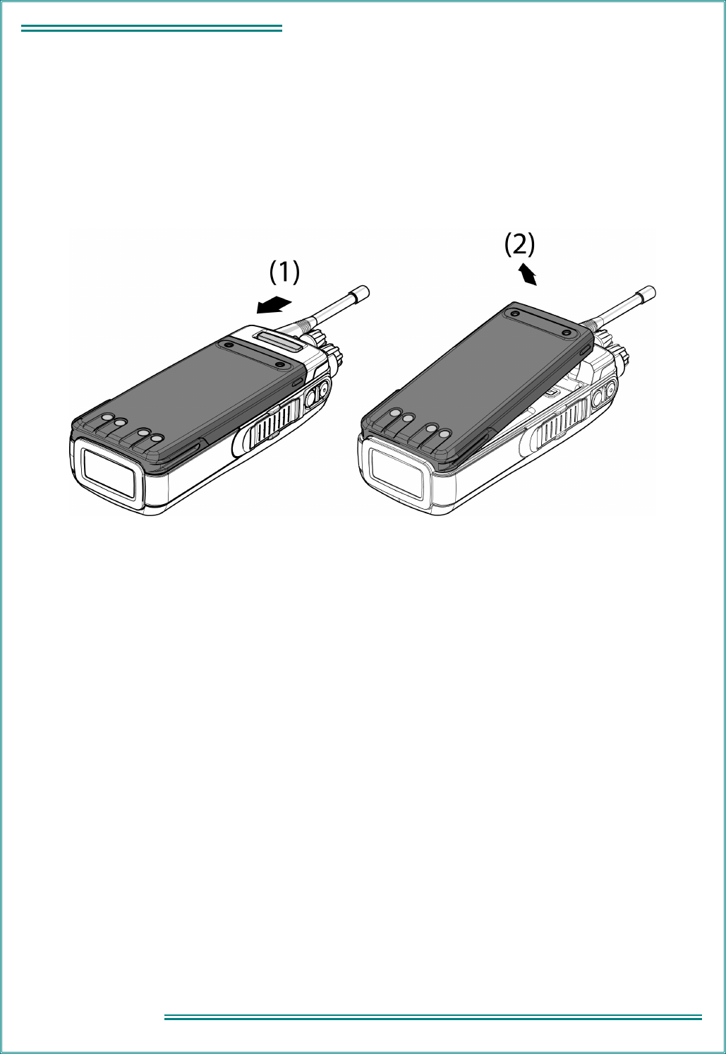
Remove the Battery
Refer Figure 3-1.
(1) Slide the battery release button towards the bottom of the transceiver to release the battery.
(2) Lift the battery away from the radio.
Figure 3-1 Battery Removal
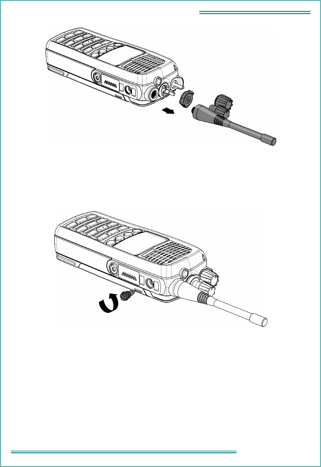
Remove the Antenna, On / Off / Volume Control Knob, Channel Control Knob, and Zone Control Lever
Refer Figure 3-2.
(1) Unscrew and remove the antenna.
(2) The On / Off / Volume Control knob is a friction-fit part. Pull the knob from the shaft.
(3) The Channel Control knob is a friction fit part. Pull the knob from its shaft.
(4) The Zone Control lever is a friction-fit part and can be removed from the switch shaft.
TNM-M-E-0023 SRP9170/80 Service Manual Issue 1.00
Page 3.2
3 -
DISASSEMBLY
Figure 3-2 Antenna and Knob Removal
Remove the Side RF Connector
Refer Figure 3-3.
Unscrew the RF connector (or dummy insert if fitted) from the side accessory connector with the removal tool (6102
790 0016) using a counter-clockwise motion.
Figure 3-3 Side RF Connector Removal
TNM-M-E-0023 SRP9170/80 Service Manual Issue 1.00
1 - INTRODUCTION Page
3.3
3 - DISASSEMBLY
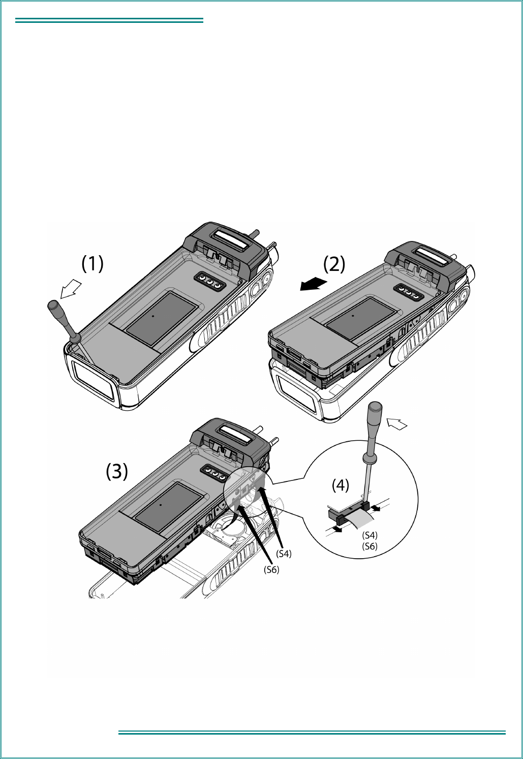
Remove the Frame Assembly
Refer Figure 3-4.
(1) Use a small, flat-blade screwdriver to carefully release the cast metal frame assembly from the bottom of the
front casing. This action releases the radio PCB from the MMI PCB.
(2) Gently ease the frame assembly out of the front casing taking care not to damage the three flex circuits. Lift the
bottom of the frame so that it just clears the plastic casing, then gently slide the frame away from the top of the
casing until it is released from the casing.
(3) Slide out the locking tab of connector S4 (on the radio PCB) to release the Accessory Flex circuit. Use a very
small flat-blade screwdriver.
(4) Slide out the locking tab of connector S6 (on the radio PCB) to release the Speaker Flex circuit. Use a very
small flat-blade screwdriver.
Figure 3-4 Removal of Frame Assembly
TNM-M-E-0023 SRP9170/80 Service Manual Issue 1.00
Page 3.4
3 -
DISASSEMBLY
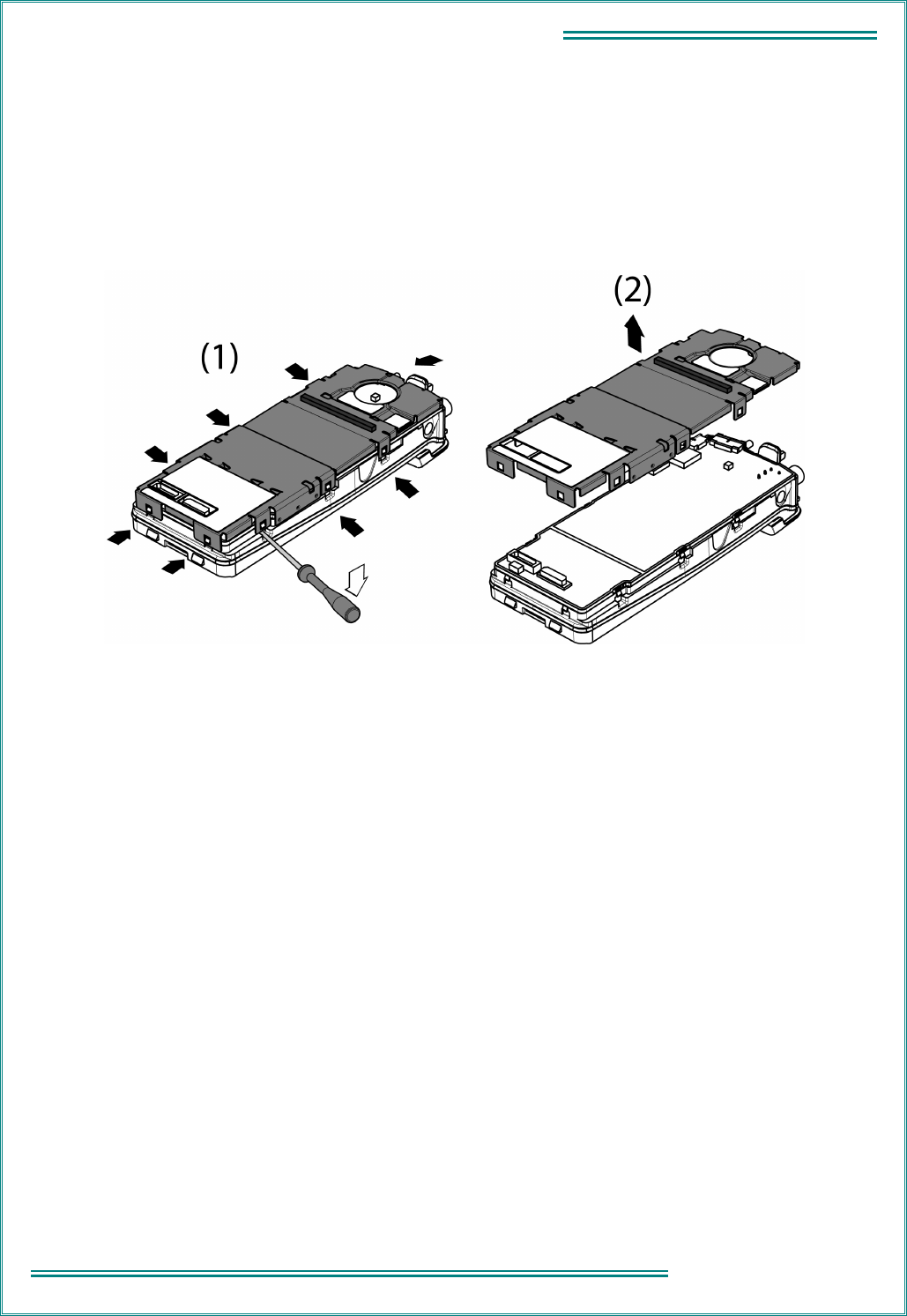
Remove the Metal Screen from the Radio PCB and Frame Assembly
Refer Figure 3-5.
(1) Use a small, flat-blade screwdriver to release the nine spring tabs on the metal screen. Note: releasing three
spring tabs on one side and the one at the top of the metal screen should be sufficient to remove the metal
screen.
(2) Lift the metal screen away from the radio PCB and frame assembly.
Figure 3-5 Removal of Metal Screen
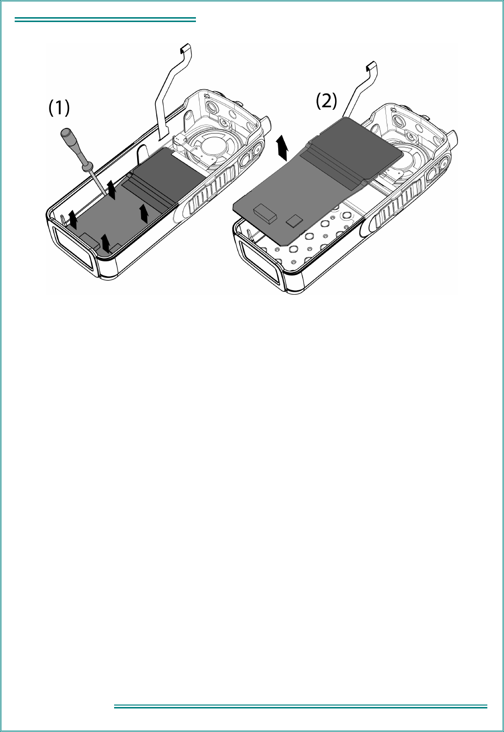
Remove the MMI Assembly
Refer Figure 3-6.
The MMI PCB is held in place by four plastic lugs on the front casing.
(1) Using a small flat-blade screwdriver, exert slight sideways and upwards pressure on the edge of the PCB (close
to one of the top retaining lugs) whilst exerting slight outward deflection of the casing side walls. This will
release the PCB from the retaining lugs.
(2) Lift the MMI PCB and LCD display assembly away from the front casing.
TNM-M-E-0023 SRP9170/80 Service Manual Issue 1.00
1 - INTRODUCTION Page
3.5
3 - DISASSEMBLY
Figure 3-6 Removal of MMI Assembly
RE-ASSEMBLY
Re-assembly is the reverse of disassembly. However:
(1) examine the various seals before re-assembly and replace with new items if necessary;
(2) slight outward deflection of the case walls will ease re-assembly of the MMI PCB behind the retaining lugs;
(3) care must be taken when reconnecting the flex circuits to ensure that they are correctly aligned before pressing
home the locking tabs on the connectors; and,
(4) ensure that the metal screen is fitted to the PCB / frame assembly before the assembly is fitted to the casing.
For radios requiring IP integrity before release back into the field, the radio must pass a calibrated Air Leak test,
subjecting the radio to a pressure equivalent to 1 m H
2
0 for 60 seconds. This test can only be performed at the
CRU, and is an essential requirement for the IS rating of a radio.

TNM-M-E-0023 SRP9170/80 Service Manual Issue 1.00
Page 3.6
3 -
DISASSEMBLY
This page intentionally left blank
TNM-M-E-0023 SRP9170/80 Service Manual Issue 1.00
Page 4.1
4 - TECHNICAL DESCRIPTION
4. TECHNICAL DESCRIPTION
4.1 R
ECEIVER
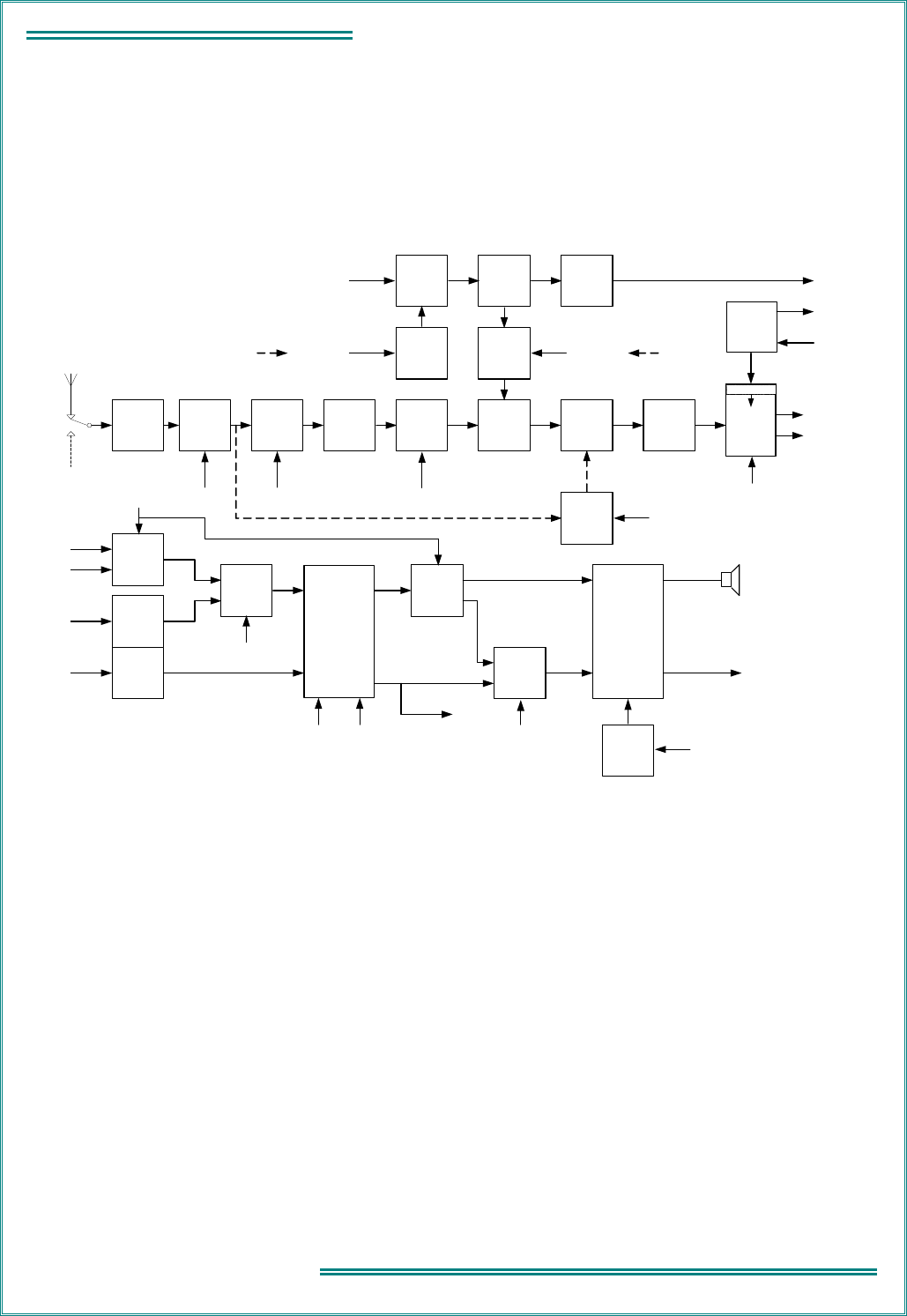
Refer to Figure 4-1. Description based on TU-band radios.
ADC/DAC
CODEC
U820
IQ
Demod
U400
S500
Harmonic
Filter
L582-L585
Antenna
Switch
D540/541/
580
Accessory
RF I/P
Bandpass
Filter
PA_ON = OFF
From PLA
Tx/Rx
Switch
D610/611
RF Amp
Q400
Bandpass
Filter
TUNE1,2
From PLA
1
st
Mixer
T400
45MHz
IF Amp
Q401
4-Pole
45MHz
IF Filters
Z401A/B
I
Q
AGC from PLA
(Integrated
PWM)
90MHz
VCO
Q402
/2
45MHz
90MHz
to U701
VCO
Control Volts
from U701
LO2
VCO
Buffer
Q604/605
Synthesiser
Buffer
Q607
to U701
Rx
VCO
Q600
Rx VCO Frequency:
UHF: Low-side injection
(RF - 45)MHz
VHF: High-side injection
(RF
+
45)MHz
Rx VCO
Enable
Switch
Q601
CPP
Rx VCO
Control Volts
from
U701
Tx_PSU = OFF
(Tx_PON = OFF) Rx_PSU = ON
(Rx_PON = ON)
Noise
Blanker
Q100 -105
(E0 Only)
BLANKER_EN
From PLA
TUNE3,4
From PLA
TX_ENABLE
From DSP
RX_ENABLE1
From DSP
SYNTH
AUX_LO2
AUX_CP
Diff. Amp
U402A
Diff. Amp
U402B
I
Q
Rx/Tx
Audio
Switch
U800A
Tx Audio
Switch
U800C
INT_MIC
EXT_MOD
TX_MODE = OFF
From PLA
From PLA From DSP
Rx Audio
Switch
U302C
Rx Audio/
Tx Mod
Switch
U302B
EXT_SW
From PLA
DATA_EN
From PLA
EXT_RX_AUDIO
(Side Accessories
Connector)
Internal
Loudspeaker
SPKR_ON
From PLA
Audio Power
Amp
U850
IN1
IN2
OUT1
OUT2
Audio
Power Amp
Enable
Switch
Q860/861
INL
INR
OUTL
OUTR
From
U400
To
U402
TX_MOD
To Tx VCO/
Phase Mod
RX-IN
Figure 4-1 VHF/UHF Receiver
4.1.1
Front-End Filters and RF Amplifier
The receiver input signal from the main antenna or accessory RF input (S500) passes through the harmonic filter
and antenna switch. With the portable in receive mode, diodes D580, D540, and D541 in the antenna switch are
reverse biased allowing the receiver input signal to be coupled through to the receiver front-end with minimal loss.
The overall insertion loss of the harmonic filter and switch is approximately 0.8 dB.
A noise blanker is also fitted to E0-band radios, enabled by an assigned function key. The noise blanker samples
the received signal and gates the 45 MHz signal in the IF stage in the event that high-level noise transients are
received. Due to inherent time delays in the band-pass filters prior to the blanking gate, gating synchronisation
occurs before the transients can adversely affect the following stages.
Varactor-tuned band-pass filters at the input and output of the RF amplifier provide receiver front-end selectivity.
Varactor tuning voltages are derived from the alignment data stored in the radio. The DSP processes this data to
optimise front end tuning relative to the programmed channel frequencies, which may be changed at any time
without re-aligning the radio.
To achieve the required varactor tuning range an arrangement of positive and negative bias power supplies is used
to provide a total reverse bias across the varactors of up to 14.0 V DC. A fixed 2.5 V positive bias, derived from the
5V0 supply using voltage divider R429 / R430, is applied to the cathodes of the varactor diodes. The control
voltages, TUNE1 to 4, for the four variable negative bias supply voltages, originate at the PLA as PWM signals. The

TNM-M-E-0023 SRP9170/80 Service Manual Issue 1.00
Page 4.2
4 - TECHNICAL DESCRIPTION
control voltages vary from 0 to 3.3 V after integration of each PWM signal. The value of each of the four control
voltages is dependent on channel frequency and tuning. Each control voltage is applied to level shifting transistors,
Q404 to Q411, where they are converted to negative voltages in the range - 0.5 V to - 11.5 V. The - 12.0 V rail of
the level translators is generated by U904D/E with D903 to D906 providing the required voltage multiplication.
The RF amplifier stage comprises a low noise transistor amplifier Q400 that is compensated to maintain good
linearity and matching for low noise. This provides excellent intermodulation and blocking performance across the
full operating range. The overall gain of the front-end is typically 14 dB for all bands.
4.1.2
First Mixer and IF Section
The output of the last front-end band-pass filter is coupled into single balanced mixer T400 / D415 which converts
the RF signal to an IF frequency of 45 MHz. The local oscillator injection level is typically + 8 dBm at T400 pin 1 with
low side injection used for UHF bands and high side for VHF bands.
Following the mixer is IF amplifier Q401 that provides approximately 15 dB of gain and in association with its output
circuitry, presents the required load conditions to the 4-pole 45 MHz crystal filters Z401A / Z401B.
The crystal filters provide part of the required selectivity for adjacent channel operation with the remaining selectivity
provided by a DSP band-pass filter algorithm.
4.1.3
IQ Demodulator
Additional IF gain of approximately 45 dB occurs at U400 which is a dedicated IF AGC amplifier / IQ Demodulator
configured for single-ended input and differential-output operation. The AGC voltage for U400 is derived from the
RSSI function of the DSP. The onset of AGC operation occurs when RF input signal level at the antenna connector
exceeds – 90 dBm and can reduce the gain by approximately 100 dB for strong signals.
Conversion of the 45 MHz IF signal to I and Q baseband signals is carried out by the demodulator section of U400.
The 90 MHz local oscillator signal is generated by VCO Q402 which is phase locked by the auxiliary PLL output of
U701 via feedback signal AUX_LO2. The 90 MHz LO2 signal is divided down to 45 MHz internally in U400.
4.1.4
Receiver Audio Processing
The baseband audio from the IQ Demodulator (U400) is applied to a differential amplifier that cancels out DC
offsets and converts the balanced demodulator IQ output signals to unbalanced inputs for the CODEC, U820.
All receiver audio processing and filtering functions are performed by the CODEC under the control of the DSP. The
receiver I and Q analogue baseband signals are converted to digital signals by the CODEC ADC before being
applied to a series of digital filters which provide the final stage of adjacent channel filtering, high-pass and low-pass
filtering, mute noise processing and volume control for narrow and wideband operation. The fully processed signal
is then converted to an analogue audio signal by the CODEC DAC and then applied to a conventional dual audio
amplifier, U850.
U850 provides an audio output level of up to 500 mW into the internal 16 ohm speaker, or external 16 ohm load.
The carrier and signalling mute functions are performed by Q860/861 under DSP control. De-emphasis of the audio
signal is performed within the DSP.
Discriminator audio is derived from the other CODEC output channel, OUTR. Discriminator audio is a preset level
set by the FPP and is independent of squelch operation. Switch U302B can select either flat or de-emphasised
audio from the CODEC. The selected audio is applied to the other half of the audio amplifier, U850, which drives
the Accessories Connector audio after which it is routed to the portable’s Side Accessories connector.
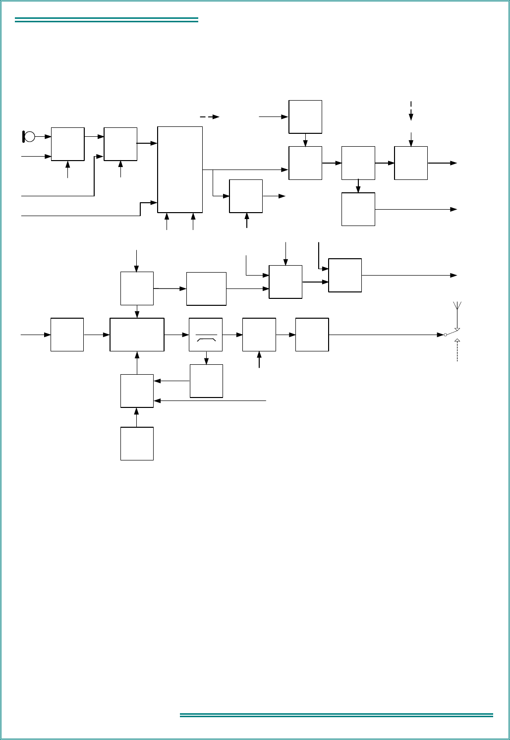
TNM-M-E-0023 SRP9170/80 Service Manual Issue 1.00
Page 4.3
4 - TECHNICAL DESCRIPTION
4.2 T
RANSMITTER
Refer Figure 4-2.
S500
Accessory
Antenna
Synthesiser
Buffer
Q607
to U701
Tx
Buffer Amp
Q550/560
Rx_PSU = OFF
(Rx_PON = OFF)
RX_ENABLE1
From DSP
TX_RF
Tx Audio
Switch
U800C
INT_MIC
EXT_MOD
EXT_SW
From PLA
Rx/Tx
Audio
Switch
U800A
TX_MODE = ON
From PLA
From IQ
Demod U400
INL
I
Q
INR
Rx Audio/
Tx Mod
Switch
U302B
DATA_EN
From PLA
TX_MOD
OUTR
ADC/DAC
CODEC
U820
From PLA From DSP
Alert Tones
to
U850
Tx
VCO
Q602
Tx VCO
Enable
Switch
Q603
Tx_PSU = ON
(Tx_PON = ON)
TX_ENABLE
From DSP
VCO
Buffer
Q604/605
Tx/Rx
Switch
D610/611
to Tx
Buffer
Amp
SYNTH
TX_RF
From Tx/Rx
Switch
Tx PA
U500
Directional
Coupler
Tx PA
Current
Sense
U520B
BAT_FS
Fused 7.2 VDC
from F900
TX_CURRENT
Tx PA
Power
Detector
D510A/B
Tx PA
Power
Control
Comparator
U520A
Thermal
Foldback
Q530/531
R532
TX_PWR
Tx PA Power Set
(Integrated PWM)
from PLA
Harmonic
Filter
L582/584/
585
Temperature
Compensation
R535/536/537
Switch
U800B
VOLUME
Switch Control
from PLA
Comparator
U301C
13 ms Ramp
from PLA
to PLA
Antenna
Switch
D540/541/
580
PA_ON = ON
From PLA
Tx RF Output (+37 dBm max.)
Figure 4-2 VHF/UHF Transmitter
4.2.1
Drivers and PA Stages
The RF output level from D611 in the VCO Tx / Rx switch is typically + 8 dBm. Tx buffer Q550/560 increases this
level by approximately 6 dB (136 to 530 MHz), 9 dB (66 to 88 MHz) and also provides a high degree of VCO
isolation from the Tx output.
The Tx PA module, U500 requires a drive power of approximately 17 dBm (335 to 520 MHz), 13 dBm (136 to 245
MHz) and 15 dBm (66 to 88 MHz). The module contains power control circuitry and MOSFET stages to provide a
maximum output power of + 37 dBm (5 W).
Caution: During servicing, if drive power is lost while the power control voltage is high, the current into the PA may
exceed its specified maximum rating. Therefore, the bench power supply current must be set to as low a value as
necessary. The radio has additional in-built safeguards, but these should not be relied on.
Power output settings are derived from alignment data stored in flash memory during the initial factory alignment.
The DSP processes this data to optimise the output power level relative to the programmed channel frequencies.

TNM-M-E-0023 SRP9170/80 Service Manual Issue 1.00
Page 4.4
4 - TECHNICAL DESCRIPTION
Comparator U520B monitors the Tx PA current through L571.The output of U520B is temperature compensated by
R535/536/537, and then passed to analogue switch U800B. Comparator U301C is used to compare the output of
U800B with a 13 ms ramp signal. The output of U301C is passed to the PLA and then processed by the DSP.
4.2.2
Power Control
Transmitter output power is stabilised by a feedback control loop. A printed-circuit directional coupler, L590, R580,
D510, and associated components form a power detector. Comparator U520A and associated components provide
the power setting and control functions. Forward power is sampled by the power detector and applied as a DC
voltage to the inverting input of the comparator. The TX_PWR set voltage is a DC voltage proportional to the
programmed transmitter power setting and is applied to the non-inverting input of the comparator.
The TX_PWR voltage originates from the PLA as a PWM signal and is integrated before applying to the
comparator.
Changes in the Tx PA module output level due to supply voltage, load, or temperature variations are detected and
applied to the comparator, U520A. The comparator output proportionally adjusts the Tx PA module gate voltage,
and therefore the Tx PA output level. High temperature protection is provided by thermistor R532 that progressively
reduces the power level if the Tx PA module temperature becomes excessive.
4.2.3
Antenna Switch and Harmonic Filter
The antenna switch, consisting of PiN diodes D580/540/541, is switched by Q541/542 and associated circuitry
allowing the transmitter output to be coupled to the antenna while providing isolation for the receiver input. With the
transmitter switched on, the diodes are forward biased, allowing power to be coupled through to the antenna and
isolating the receiver by grounding its input at C588. The short circuit at the receiver input is transformed to an
effective open circuit at D580 by L583, which minimises transmitter loading. With the transmitter switched off the
diodes are reverse biased allowing the receiver input signal to reach the receiver front end with minimal loss. The
harmonic rejection low pass filter comprises L582/584/585 and associated capacitors.
A mechanical changeover switch, S500, is provided to allow connection of an external antenna.
4.2.4
Transmitter Audio Processing
The internal electret microphone provides 10 mV RMS (nominal), to give approximately 60% of maximum system
deviation. Analogue switch, U800C, switches between the internal microphone audio signal and external audio
options and data input.
U800A provides CODEC (U820) input switching which selects either the receiver I signal or transmitter audio/data
signals depending on the Tx / Rx mode. All pre-emphasis, filtering, compression, and limiting processes for narrow
and wideband operation are carried out in the DSP after A to D conversion by the CODEC. The processed
transmitter audio/data from the CODEC output at VOUTR is applied to the VCO as a modulation signal with a level
of approximately 200 mV p-p.
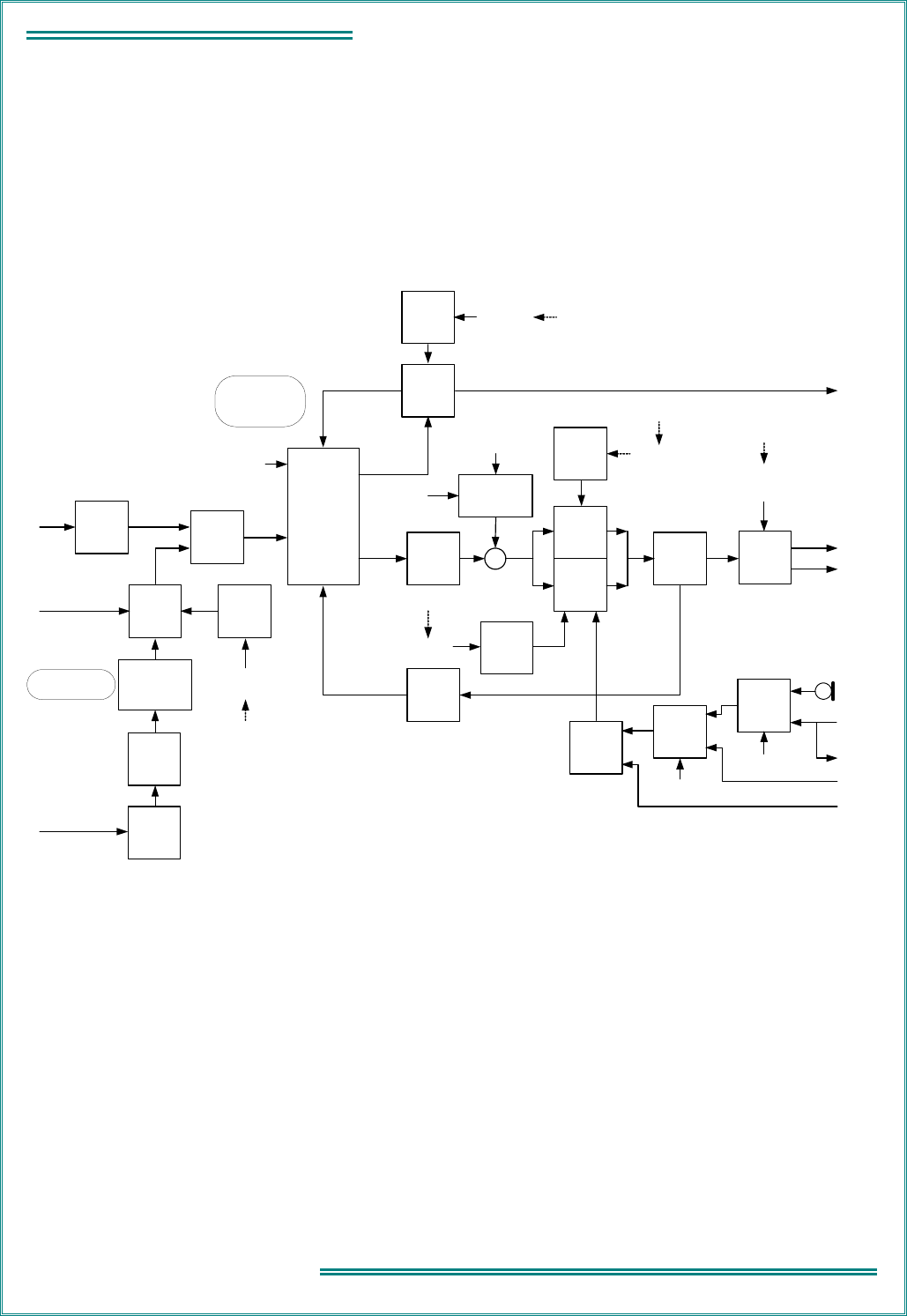
TNM-M-E-0023 SRP9170/80 Service Manual Issue 1.00
Page 4.5
4 - TECHNICAL DESCRIPTION
4.3 P
HASE
-L
OCKED LOOP
(PLL) F
REQUENCY
S
YNTHESISER
4.3.1
General
Refer to Figure 4-3.
The PLL frequency synthesiser consists of one transmitter VCO, two receiver VCOs, loop filters, varactor negative-
voltage bias generator, reference oscillator, and an integrated, fractional-N and integer-N synthesiser device U701.
When combined, these components form the main and auxiliary PLL frequency synthesisers.
Divider:
1/30 UHF (480 kHz)
1/60 VHF (240 kHz)
Synthesiser
Buffer
Q607
Synthesiser
U701
Synth
Control
from DSP
U201
Tx
VCO
Q602
TX_ENABLE = ON
from DSP U201
VCO
Buffer
Q604/605
Tx/Rx
Switch
D610/611
PLL
Loop Filter
Tx VCO
Enable
Switch
Q603
Rx
VCO
Q600
CPP
Rx VCO
Enable
Switch
Q601
+
VCO Varicap
Negative Bias
Supply
Q700/701/702/703
VCAP_BIAS
VCAP_ADJ
from PLA U300
Rx_PSU
(Rx_PON)
OFF = Tx
ON = Rx
RX_ENABLE1
from DSP U201
OFF = Tx
ON = Rx
Tx_PSU = OFF
(Tx_PON = OFF)
TX_ENABLE = OFF
from DSP U201
Tx_PSU = ON
(Tx_PON = ON)
LO1_RX
TX_RF
to
TX Buffer
to
Rx Mixer
SYNTH
90MHz
VCO
Q402
AUX_CP
LO2 to
IQ Demod
U400
AUX_LO2
90MHz
VCO
Disable
Switch
Q412
TX_ENABLE
from DSP U201
ON = 90MHz disable
Tx_PSU
(Tx_PON)
ON = 90MHz disable
14.4MHz
Reference
Osc.
U700
Buffer
Q710
Programmable
Frequency
Divider
U710
Ramp
Generator
Q711/712/
713
Schmitt
Trigger
Q714/715/
716
Integrator
U760
TX_MOD
from
CODEC
U820
CODEC
U820
TX_MOD
Tx Audio
Switch
U800C
INT_MIC
EXT_MOD
from Access. Conn.
EXT_SW
from PLA U300
Rx/Tx
Audio
Switch
U800A
TX_MODE = ON
from PLA U300 from IQ Demod
U400
I
Q
EXT_SENSE
to PLA U300
RF Reference:
480 kHz (UHF)
240 kHz (VHF)
IF Reference:
40 kHz
AFC
from
PLA
U300
Rx Ramp
Enable
Switch
Q717
Rx_PSU
(Rx_PON)
ON = Rx Ramp
RX_ENABLE1
from DSP U201
ON = Rx Ramp
MOD_BAL
from PLA U300
(integrated PWM)
-16VDC
REFIN
Figure 4-3 VHF/UHF Frequency Synthesiser
4.3.2
Integrated Synthesiser
The synthesiser device, U701, contains two prescalers, two programmable dividers, and two phase comparators, to
provide a main and an auxiliary synthesiser. The main synthesiser controls the frequency of the Tx / Rx VCOs via
the control voltage output at pin 1 and VCO feedback to pin 4. The auxiliary synthesiser is used to control the
receiver 90 MHz second local oscillator via the control voltage output at pin 16 and VCO feedback to pin 13. The
main synthesiser is a fractional-N device, and the auxiliary synthesiser is an integer-N device.
4.3.2.1 Main Synthesiser
The main fractional-N synthesiser divides the output of the Tx or Rx VCO down to the value of the comparison
frequency. The comparison frequency is either 480 kHz (UHF) or 240 kHz (VHF). Programmable frequency divider,
U710, divides the 14.4 MHz reference oscillator, U700, down to 480 kHz (UHF) or 240 kHz (VHF). The divided-
down frequency is then compared by the main synthesiser phase comparator. If the two signals differ in phase or

TNM-M-E-0023 SRP9170/80 Service Manual Issue 1.00
Page 4.6
4 - TECHNICAL DESCRIPTION
frequency, an error signal is generated by the phase comparator. This error signal forces the VCO to change
frequency in a direction to minimise the error signal.
A valid lock detect output is derived from pin 12 and is sampled by the PLA. During transmit, if an unlocked signal is
detected the radio will switch back to receive mode. An unlocked signal in receive mode will cause the radio to
beep.
4.3.2.2 Auxilliary Synthesiser
The auxiliary integer-N synthesiser is used to generate the second LO frequency, 90 MHz. The comparison
frequency for this synthesiser is 40 kHz.
4.3.3
VCOs
The transmitter and receiver VCOs use low noise JFET transistors Q600 (Rx), Q602 (Tx) and associated parts to
generate the signals for the required band coverage. Electronic tuning is provided by varactor diodes D600 to D608
with their control voltages derived from the loop filter (C636, C640, C671, C675, C681, C682, C686, C691, R683,
R684, R685), and Negative Bias Generator. VCO selection and timing is controlled by the DSP / PLA via the Rx
and Tx power supplies and applied through switches Q601 (Rx) and Q603 (Tx). VCO buffer Q604 / Q605 isolates
the VCO from load variations in following circuits and active power supply filter Q615 minimises supply related
noise. A PLL feedback signal is sampled from the VCO buffer output via buffer Q607.
The 90 MHz receiver VCO comprises Q402 and associated parts. Automatic tuning is achieved by applying a
Control Voltage to D408 / D409 via Loop Filter R433, R445, R464, C467, C493 and C467a.
4.3.4
Negative Bias Generator and Loop Filter
A positive and negative varactor bias supply, similar to the front-end varactor arrangement, is used to achieve the
required broadband tuning range of the VCOs. PLL device U701 is programmed to deliver a nominal + 1.6 V output
from phase detector/charge pump CPP regardless of the channel frequency selected. This voltage is filtered by the
loop filter to remove synthesiser noise and reference frequency products. The resulting low noise voltage is applied
to the cathode side of the VCO varactor tuning diodes as a positive bias voltage.
The negative bias supply originates as an integrated PWM voltage (0.1 V to 3.3 V) at the VCAP_ADJ output of the
PLA, with a level relative to the programmed state of the radio (e.g. channel frequency and Tx or Rx mode). The
voltage is translated to a negative voltage between 0 V and – 16 V by the circuit comprising Q700 to Q703. The
– 16 V rail of this supply is generated by U904E/D with D903 to D906 providing the voltage multiplying effect
needed to achieve – 16 V. The output of the negative supply is applied directly to the VCO varactor anodes as the
negative tuning voltage VCAP_BIAS.
4.3.5
Phase Modulator
The modulation path for audio, data and higher frequency CTCSS signals is via varactor D609 and its associated
components in the Tx VCO. The reference input to the synthesiser (U701 - REFIN) provides the low frequency
modulation path via the Phase Modulator.
The phase modulator comprises the following sections:
• integrator U760B is a low pass filter providing 6 dB per octave attenuation to frequencies above
approximately 1 Hz;
• divider U710 divides the 14.4 MHz reference frequency down to 240 kHz (VHF) or 480 kHz (UHF);
• ramp generator Q711 / Q712 provides a saw tooth output, the slope of which is adjustable via the
MOD_BAL line. This adjustment is set via a DAC output controlled from the Alignment Tool.
Adjustment of the ramp slope effectively changes the Phase Modulator gain by modification of the
Schmitt trigger switching points after modulation from the Integrator is combined to the saw tooth ramp.
The divided reference signal is differentiated and discharges C744 via Q711 after which Q711 is turned
off allowing C744 to recharge via constant current source Q712; and,
• Schmitt trigger comprising Q714 to Q716 converts the modulation combined with the saw tooth ramp to
a square wave output, the duty cycle of which is controlled by the ramp slope and modulation.
The modulation balance setting is carried out during alignment using a 100 Hz square wave (generated by
the CODEC, U820) applied to the TX_MOD input and adjusted to give an optimum demodulated square
wave output.
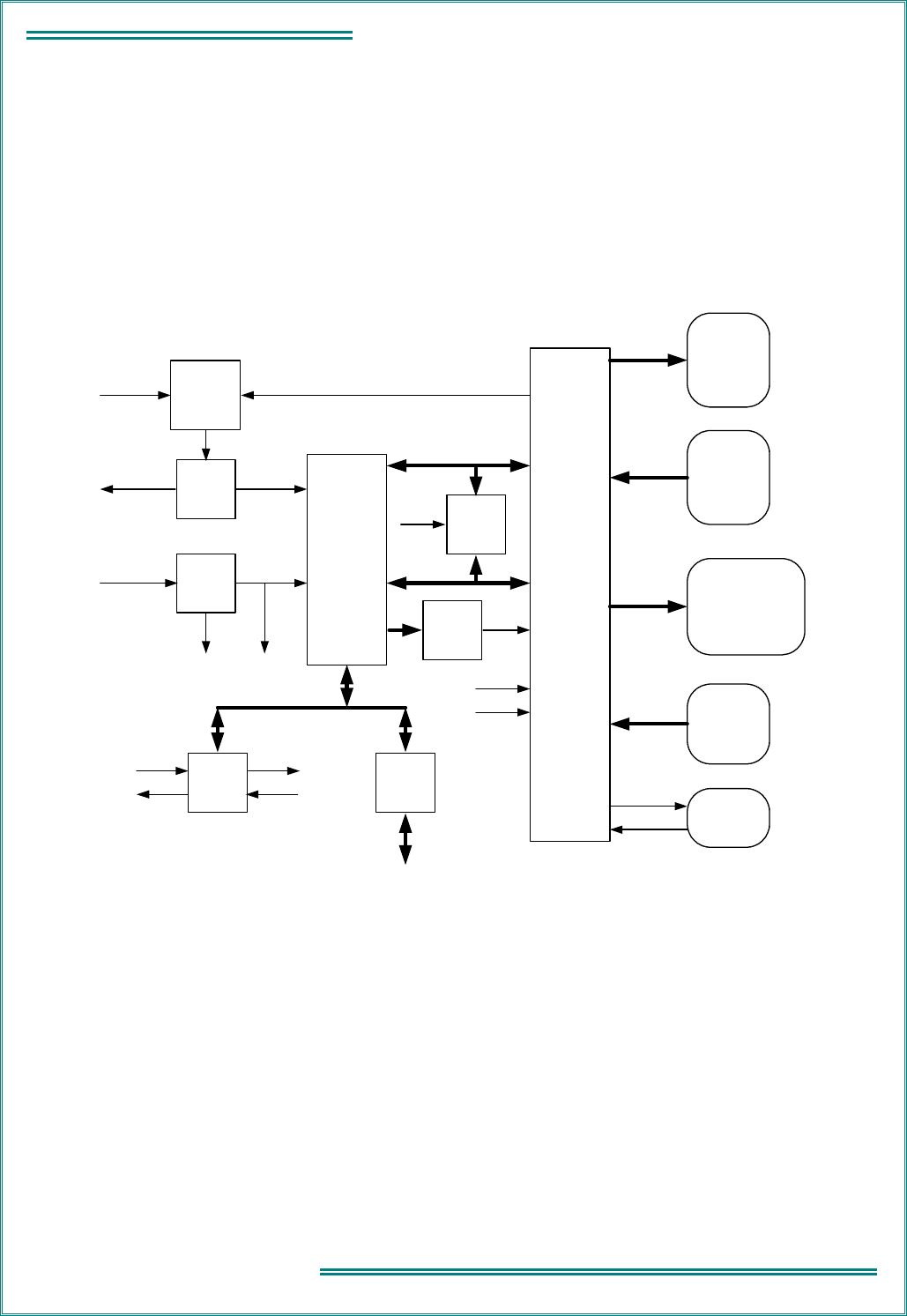
TNM-M-E-0023 SRP9170/80 Service Manual Issue 1.00
Page 4.7
4 - TECHNICAL DESCRIPTION
4.3.6
Reference Oscillator
The TCXO, U700, determines the overall frequency stability and frequency accuracy of the radio. The frequency
setting is achieved by adjusting its ADJ voltage with the Alignment Tool. In addition, the ADJ input is used in a
frequency control loop with the receiver I and Q signals to provide receiver AFC. U700 operates at 14.4 MHz
and is specified at ± 1.5 ppm frequency stability over the temperature range – 30 °C to + 80 °C.
4.4 S
YSTEM
C
ONTROLLER
Refer to Figure 4-4.
DSP
U201
TX_PSU
Voltage
Monitor/
Reset
Supervisor
U200
15.36MHz
DSP
Clock
X200
BAT_SENSE
from
Power Supply
PLA
U300
DSP
Clock Control
Q200/201/202
DSP_CLK
from
switched
battery volts
BAT_SW
XTAL_SHIFT
Flash
Memory
U202
Synthesiser
U701
LOCK
Data
Address
Control
CODEC
U820
Control
Tx AudioRx Audio
Integrated PWM Analogue Outputs
Sampled Analogue Inputs
Bit Outputs
BLITE
SPKR_ON
PA_ON
TX_MODE
EXT_SW
PWR_OFF
RED
GREEN
Analogue Switch Control
/RESET
CLKIN
/RESETLB_RESET
/RESET
/RESET
Low battery
reset
System
reset
Bit Inputs
LB_RESET
PWR_SENSE
PTT_IN1
PTT_IN2
AK1
AK2
SK1
SK2
LOOP_VOLTS
KEY_DET
TX_CURRENT
VOLUME
EXT_SENSE
BAT_SW
ZONE
CHANNEL
TUNE1 to TUNE4
MOD_BAL
AGC
AFC
TX_PWR
FUNCTION_EN
VCAP_ADJ
CODEC
U1
Options
Port
Serial Port
TX_DATA
RX_DATA
Figure 4-4 System Controller Block Diagram
4.4.1
DSP and PLA
The SRP9170/80 transceiver operates under the control of a DSP (U201) and PLA (U300) combination that
together with a number of other dedicated devices perform all the operational and processing functions required by
the radio. The PLA is configured by the DSP under software control to provide the following functions:
• channel set-up of operating frequencies;
• modulation processing and filtering;
• demodulation processing and filtering;
• Tx power output reference;

TNM-M-E-0023 SRP9170/80 Service Manual Issue 1.00
Page 4.8
4 - TECHNICAL DESCRIPTION
• modulation balance adjustment;
• receiver front-end tuning;
• serial communications with alignment tool, microphone and control head;
• modem functionality for data modulation;
• all signalling / CTCSS generation and decoding;
• DSP crystal oscillator control;
• receiver muting control;
• RSSI / AGC control;
• AFC;
• Tx / Rx switching and PTT control;
• PLL lock detect;
• audio switching;
• power ON /OFF control;
• interface functionality with option boards and external devices; and,
• battery voltage and Tx current monitor.
4.4.2
DSP Clock Oscillator
The DSP is clocked by a 15.360 MHz oscillator that consists of crystal X200 and an internal DSP oscillator circuit.
Q200, Q201, Q202 form a crystal switching circuit with C205 which, when activated by a command (XTAL_SHIFT)
from the PLA, steers the oscillator away from potential interfering frequencies.
4.4.3
PLA PWM
4.4.3.1 Analogue Outputs
The PLA generates several analogue signals to control radio tuning. These outputs are derived from PWM signals.
The front-end analogue tune values (TUNE1 to TUNE4) originate from the PLA in the form of integrated PWM
signals. The values for these signals are stored in flash memory from radio alignment and selected depending on
the channel that the radio is currently tuned to. These signals are integrated by RC networks to provide the
analogue tuning voltages that are ultimately applied to the varactor tuning diodes.
Other analogue PWM derived signals used are:
• transmitter power (TX_PWR);
• receiver AGC voltage (AGC);
• receiver AFC voltage (AFC);
• function enable (FUNCTION_EN);
• varactor VCO tuning diode bias adjustment (VCAP_ADJ); and,
• modulation balance (MOD_BAL).
4.4.3.2 Analogue Inputs
Analogue inputs are monitored by comparators. Comparators U301A, B, C, D and U303A, B have their non-
inverting inputs connected to a periodic ramp voltage generator, derived from a PWM signal from the PLA.
Analogue voltages to be monitored are connected to the comparator inverting inputs. The analogue voltages are
compared with the increasing ramp voltage. The comparator switches at the point where the ramp voltage exceeds
the monitored voltage. The PLA determines the ramp signal time that this occurs, and converts it to a binary value.

TNM-M-E-0023 SRP9170/80 Service Manual Issue 1.00
Page 4.9
4 - TECHNICAL DESCRIPTION
The monitored analogue voltages are:
• Tx/Rx frequency synthesiser loop volts (LOOP_VOLTS);
• MMI key detection (KEY_DET);
• Tx PA current (TX_CURRENT);
• Transceiver audio volume (VOLUME);
• type of external device detection (EXT_SENSE);
• battery voltage (BAT_SW);
• Zone Switch value (ZONE); and,
• Channel Switch value (CHANNEL).
4.4.4
Digital I/O
4.4.4.1 Bit Outputs
Several ON / OFF digital outputs are used to control various sections of the transceiver:
• enable/disable transceiver audio output (SPKR_ON);
• control Tx / Rx PiN diode switch for Tx or Rx mode (PA_ON);
• control Tx / Rx audio switch, U800A (TX_MODE);
• control Tx audio source switch, U800C (EXT_SW);
• switch off transceiver DC supply (PWR_OFF);
• control Tx LED (RED);
• control Rx LED (GREEN);
• control MMI backlight (BLITE); and,
• various analogue switch on / off control.
4.4.4.2 Bit Inputs
The system controller scans various digital inputs to determine the state of the transceiver:
• battery voltage (PWR_SENS);
• Press-to-Talk switch status (PTT_IN1, PTT_IN2);
• Accessory Key status (AK1, AK2); and,
• Side Key status (SK1, SK2).
4.4.5
System Memory
System memory consists of the internal DSP memory and an external 8 MB non-volatile flash memory U202. When
power is off, all program software and data are retained in flash memory. At power-on, a boot program downloads
the DSP and PLA software from flash memory to their internal RAM for faster program execution and access to
data. PLA software is loaded by the factory into the flash memory and can be updated via the Alignment Tool. DSP
software comprises Startup code that is also loaded by the factory. High-level software comprising Operational
Code and Customer Configuration are loaded at distribution centres and are loaded via the FPP Programmer.

TNM-M-E-0023 SRP9170/80 Service Manual Issue 1.00
Page 4.10
4 - TECHNICAL DESCRIPTION
4.4.6
Serial Data Interface
A serial data port is provided on the side accessories connector, S4. The serial data interface supports the following
signals:
4.4.6.1 Receive Data (RxD1_In)
Transistors Q90 and 91 form an inverting buffer that translates the incoming data stream to 0 to 3 V logic. The
following serial data voltage levels are supported when the appropriate accessory cable is used:
• RS232
• TTL
• USB
Transceiver software detects the type of peripheral connected to the accessories connector and inverts the
incoming data if required. A pull-up resistor to + 5 V, R88a, is provide for external devices with open-collector
(drain) outputs.
4.4.6.2 Transmit Data (TxD1_Out)
Serial data out is 0 to + 5 V levels. The serial driver, Q80, 81, 82, 83 can also be used as a + 5 V / 100 mA DC
source.
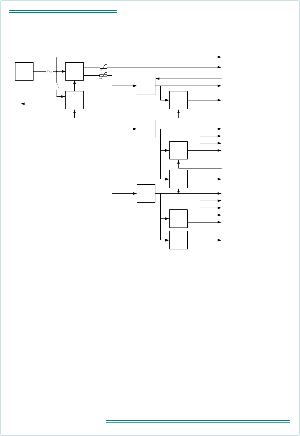
TNM-M-E-0023 SRP9170/80 Service Manual Issue 1.00
Page 4.11
4 - TECHNICAL DESCRIPTION
4.5 P
OWER
S
UPPLIES
Refer to Figure 4-5.
PWR_OFF
Q900
Control
Q908,909
Switch
Q900
ON/OFF
from
PLA (U300)
F900
4A
Battery
7.2V
to
PLA (U300)
PWR_SENSE
F902
F903
BAT_SW
BAT_FS
PWR_ON
BAT_FS
RF PA (U500)
Audio PA (U850), Accessories (S4)
+5V
Regulator
U900
5VR
Switch
Q903
RX_PSU
RX_PON from DSP (U201)
+5V
Regulator
U901
STBY from PLA (U300)
+5V
5V0
VCO_PSU
Switch
Q910
3Q3
+3V3
Switching
Regulator
U902
3V3
3C3
3P3
-16V
Inverter
U904
-16V
-12V
+2V5
Regulator
U903
2V5
Switch
Q904
TX_PON
TX_PSU
From DSP (U201)
90MHz VCO (Q402), Ref Osc (U700), Phase Mod
(Q715,716), Ref Divider (U710)
1
st
IF Amp (Q401), RF Amp (Q400), Noise Blanker
(Q106), T/R Switch (D610,611), Mod Bal Switch
(Q717), DSP Clock Switch (Q201)
Rx BPF Varicap Bias (R429,430), Rx/Tx VCO Switch
(Q601), IQ Buffer (U402), Synth Buffer (Q607), VCO
Varicap Neg Supply (Q700,701)
Tx/Rx VCO
90MHz VCO Switch (Q412), Tx Current Monitor
(U520B), Tx Power Comparator (U520A), Tx Buffer
(Q550,560), DSP Clock Switch (Q202)
IQ Demod (U400)
PLA (U300), DSP (U201), CODEC (U820), Flash
Memory (U202), Reset Supervisor (U200)
CODEC (U820)
Rx BPF Tune Bias (R469), Synthesiser (U701)
VCO Varicap Neg Supply (Q700,701)
Rx BPF Tune Bias (TUNE1,2,3,4)
DSP Clock (Q200), DSP (U201)
General power reticulation
Figure 4-5 Power Supply
4.5.1
Power On Function
The unregulated battery input (6.4 V ~ 9.6 V DC) is routed directly to all high current devices after the battery fuse
and is also switched via FET Q900 to provide power for all other circuits. The output from Q900 feeds three low
dropout series regulators (U905 not fitted), switched battery voltage and a switch-mode 3.3 V DC supply. These
regulated supplies power auxiliary supplies as well as the negative voltage generator. The radio On /Off function is
achieved through Q908 and Q909. The On/Off switch is connected between unswitched fused battery, BAT_FS,
and PWR_ON. When the switch is turned on, a DC pulse is applied to Q908 that turns on the main FET switch
Q900 for approximately 1 sec. In this time, the PLA samples the PWR_SENSE line and determines the state of the
On/Off switch. If the On / Off switch is on, the PLA raises the PWR_OFF line and latches the main FET on, which
then maintains power to the radio circuitry.
The power off operation requires the On / Off switch to be turned off for more than 2 seconds. If the On / Off switch
is sensed going low by the DSP via the PWR_SENSE line, the DSP will save radio settings and then lower the
PWR_OFF line, thereby turning Q900 off.

TNM-M-E-0023 SRP9170/80 Service Manual Issue 1.00
Page 4.12
4 - TECHNICAL DESCRIPTION
4.5.2
Power Supply Detail
The following is a list of the SRP91X0 power supplies and some of the devices and circuits they supply.
4.5.2.1 5V Regulator U900
This regulator can be powered down by a STBY signal from the PLA. The RX_PSU supply is switched via Q903.
Circuits supplied by U900 are:
• 5VR to synthesiser reference oscillator (U700), divider (U710), and phase modulator;
• 5VR to 90 MHz VCO (Q402);
• switched RX_PSU to VCO output switch (D610, 611);
• switched RX_PSU to noise blanker (Q106);
• switched RX_PSU to phase modulator mod balance switch (Q717);
• switched RX_PSU to DSP clock switch (Q201); and,
• switched RX_PSU to receive front end (Q400) and 1
st
IF amp (Q401).
4.5.2.2 5V Regulator U901
The TX_PSU supply is switched via Q904. Circuits supplied by U901 are:
• + 5 V is general power reticulation to the transceiver;
• 5V0 to Rx BPF varactor bias (R429, 430);
• 5V0 to Rx / Tx VCO switch (Q601);
• 5V0 to IQ buffer (U402);
• 5V0 to synth buffer (Q607);
• 5V0 to Tx / Rx VCO varactor negative supply (Q700, 701);
• VCO_PSU to Tx / Rx VCO;
• switched TX_PSU to 90 MHz VCO switch (Q412);
• switched TX_PSU to Tx current monitor (U520B);
• switched TX_PSU to Tx power comparator (U520A);
• switched TX_PSU to Tx buffer (Q550, 560); and,
• switched TX_PSU to DSP clock switch (Q202).
U901 also supplies the 3Q3 switch (Q910). The 3Q3 supplies the IQ demodulator (U400).
4.5.2.3 3.3V Regulator U902/Q918
U902/Q918 forms a 3.3 V switching regulator. Circuits supplied by this regulator are:
• 3V3 to PLA (U300);
• 3V3 to DSP (U201);
• 3V3 to CODEC (U820);
• 3V3 to flash memory (U202);
• 3V3 to reset supervisor (U200);
• 3V3 to + 2.5 V regulator (U903) which supplies the DSP clock (Q200) and the DSP (U201);
• 3V3 to – 16 V inverter (U904) which supplies – 16 V to Tx / Rx VCO negative supply (Q700, 701), and
– 12 V to Rx BPF tune bias (TUNE 1, 2, 3, 4);
• 3C3 to CODEC (U820);

TNM-M-E-0023 SRP9170/80 Service Manual Issue 1.00
Page 4.13
4 - TECHNICAL DESCRIPTION
• 3P3 to Rx BPF tune bias (R469); and,
• 3P3 to synthesiser (U701).
4.5.2.4 Un-Switched Fused Battery
• BAT_FS supplies the RF PA (U500).
• BAT_FS supplies the transceiver On / Off switch.
4.5.2.5 Switched Battery
• BAT_SW supplies the audio PA (U850).
• BAT_SW supplies the Accessories Connector (S4).
4.6 K
EYBOARD AND
G
RAPHIC
D
ISPLAY
MMI
The transceiver interfaces to the MMI assembly via connector S5 (transceiver) and J1 (MMI).
Refer Figure 4-6.
LCD
Driver
Interface
Circuits
LCD Assembly
LCD
Keypad
Backlight
J1
D0 to D7
KEY_DET3
LCD_CCS
KEY_ROW1
A20
KEY_ROW2
BLITE
AF_PSU
BAT+_FS
Figure 4-6 Keyboard and Graphic Display MMI
4.6.1
Keypad
Electronically, the keypad keys are arranged in a matrix of 3 rows and 7 columns.
The rows are driven directly by two signals KEYROW1 and KEYROW2 that are normally in the low state.
Transistors Q910 to 916 generate a unique voltage on KEYDET3 for each column (COL1 to COL7). Any key in the
same column generates the same voltage.
For example, if key “1” (SW1) is pressed Q913 turns on and sets up a voltage on KEYDET3 according to the value
of R932, R971 on the MMI board and R343 on the main radio board. The activated key value is determined using
the analogue-to-digital conversion scheme discussed in para. 4.4.3.2.
The MMI is backlit by a matrix of white LEDs, controlled by the BLIGHT (On or Off) line from the main transceiver
PCB.
4.6.2
LCD Assembly Interface
The LCD assembly incorporates the LCD driver. The LCD is a 102 (H) x 64 (V) dot graphic display. The display
assembly interfaces to the transceiver PCB via connector D100 using an 8-bit data bus (D0 to D7), write data
control (WR*), read data control (RD*), and register select (A20) lines.

TNM-M-E-0023 SRP9170/80 Service Manual Issue 1.00
Page 4.14
4 - TECHNICAL DESCRIPTION
4.6.3
MMI Interface Signals
S5 Signal Name J1 Signal Name Function Signal Type
0VA (1) LCDRW (1) Not used 0 V
D3 (2) D3 (2) Data bit 3 0 V or 5 V
D5 (3) D5 (3) Data bit 5 0 V or 5 V
D2 (4) D2 (4) Data bit 2 0 V or 5 V
D6 (5) D6 (5) Data bit 6 0 V or 5 V
D0 (6) D0 (6) Data bit 0 0 V or 5 V
D7 (7) D7 (7) Data bit 7 0 V or 5 V
D1 (8) D1 (8) Data bit 1 0 V or 5 V
D4 (9) D4 (9) Data bit 4 0 V or 5 V
LCD_CCS (10) WR* (10) Write data to MMI 0 V or 5 V, active low
0VA (11) GND (11) Ground 0 V
KEY_ROW1 (12) KEYROW1 (12) Keypad row 1 enable 0 V or 5 V, active low
AF_PSU (13) AF_PSU (13) Power supply 5 V nominal (from + 5V)
KEY_ROW2 (14) KEYROW2 (14) Keypad row 2 enable 0 V or 5 V, active low
N/C (15) N/C (15) TP1 Test point
BLITE (16) BLIGHT (16) Backlight enable 0 V OFF, 5 V ON
BAT+_FS (17) BAT+FS (17) Backlight power supply 7.2 V DC (nominal)
KEY_DET3 (18) KEYDET3 (18) Voltage proportional to key value 0 V to 5 V
A20 (19) A20 (19) Register select 0 V or 5 V
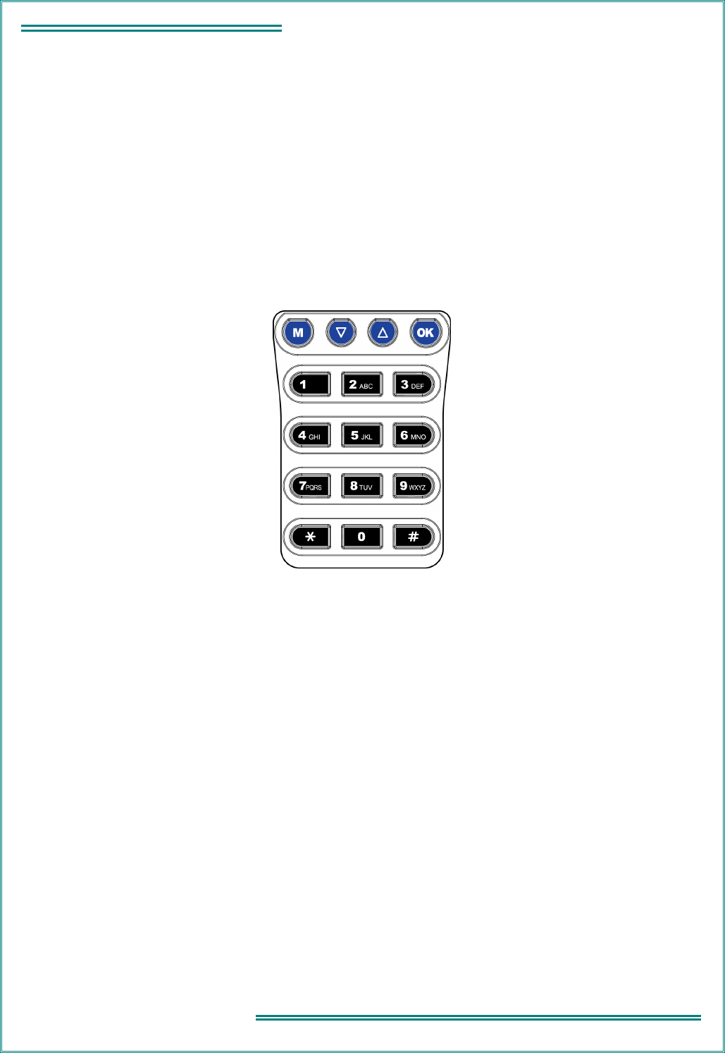
TNM-M-E-0023 SRP9170/80 Service Manual Issue 1.00
Page 4.15
4 - TECHNICAL DESCRIPTION
4.6.4
Function Keys
Four function keys are located below the display:
Legend Function
M Activate menu.
\/ Scroll down through channels (or menu, if active).
/\ Scroll up through channels (or menu, if active).
OK Confirm choice or action (i.e. Enter).
The SRP9180 has 12 additional keys arranged as a DTMF keypad.
Figure 4-7 Keypad Layout

TNM-M-E-0023 SRP9170/80 Service Manual Issue 1.00
Page 4.16
4 - TECHNICAL DESCRIPTION
This Page Intentionally Left Blank

TNM-M-E-0023 SRP9170/80 Service Manual Issue 1.00
Page
5.1
5 - ALIGNMENT
5. ALIGNMENT (LEVEL 3 SERVICE ONLY)
This procedure is applicable to all versions of SRP9170/80 portable transceivers.
If the radio contains customer configuration data that must be retained, you must first use the SRM / SRP
Field Personality Programmer (FPP) software to read all radio configuration files and save them on to
alternative media before commencing the alignment procedure.
When the alignment is completed, use the FPP software to retrieve this stored data and write it back to the
radio.
It is preferred that the radio remains installed in its chassis so that appropriate shielding and battery supply
are maintained.
Note: Final Tx power adjustments must be performed with the radio board installed in the chassis.
5.1 T
EST
E
QUIPMENT
1. Radio transceiver test set. CMT, 52/82 or similar.
Note: for alternative equipment, the Mod
Balance test requires internal DC
coupling between the demodulated
signal and demodulation output
connector.
2. Variable DC power supply. 6.4 V to 9.6 V at 2.5 A
3. Oscilloscope. 20 MHz bandwidth (minimum).
4. SRP9170/80 Programming & Alignment Lead.
PAR-9180PRLDU
5. SRP9170/80 Radio Test Interface Unit, or
simple interface circuit in Fig 5.2.
PAR-9180RTIU
6. PC. 486 DX 66 or better.
Operating system Windows 95 or later.
Minimum RAM – 16 MB.
5 MB free hard disk space.
Floppy drive - 1.44 MB.
Mouse and serial port required.
7. SRM / SRP Alignment Tool. Computer Software file.
8. SRM/SRP Field Personality Programmer
(FPP).
Computer Software file.
9. SRP9170/80 Battery Eliminator.
10. Antenna Adaptor for Portable. PA-ACON
Caution
Preparing the radio for alignment will erase from the radio all customer PMR and Trunking
configuration data (chann
el, signalling information etc). The only data retained by the Alignment
Tool is the factory alignment data for the radio (DAC settings for Tx power, front-end tuning etc).
Using the Alignment Tool will allow changes to the original factory alignment and w
ill invalidate
all warranties and guarantees unless performed by an authorised level-3 service centre.
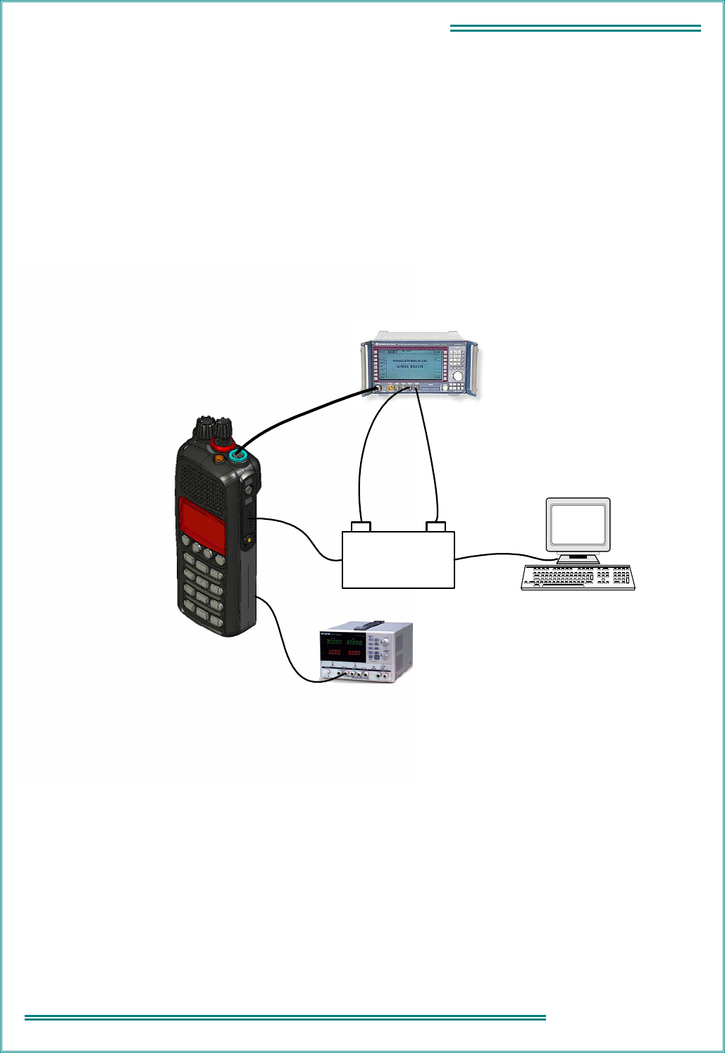
TNM-M-E-0023 SRP9170/80 Service Manual Issue 1.00
Page 5.2
5 - ALIGNMENT
5.2 T
EST
S
ET
-
UP
Refer Figure 5-1.
Notes for test setup:
1. The PTT switch on the Radio Test Interface Unit (refer Figure 5-2) activates transmit on the
transceiver.
2. Interface data levels are TTL with RS232 polarity (i.e. 0 V = MARK, + 5 V = SPACE), and will work
with most personal computers.
3. The 16 R resistor in the Radio Test Interface Unit simulates the speaker load.
Radio Transceiver Test Set
PC Serial Port
RX Audio
TX Audio
Antenna
M5
Accessories
Connector
Power Supply
Radio Test
Interface Unit
`
Battery
Simulator
Figure 5-1 Test Set-Up
Notes:
1. Connect the radio to the test equipment as shown in Figure 5-1.
2. Use an adaptor (P/N PA-ACON) to provide a coaxial antenna socket termination on the radio.
3. A battery eliminator is used to supply power to the portable. This is an empty battery pack with external
DC connections.
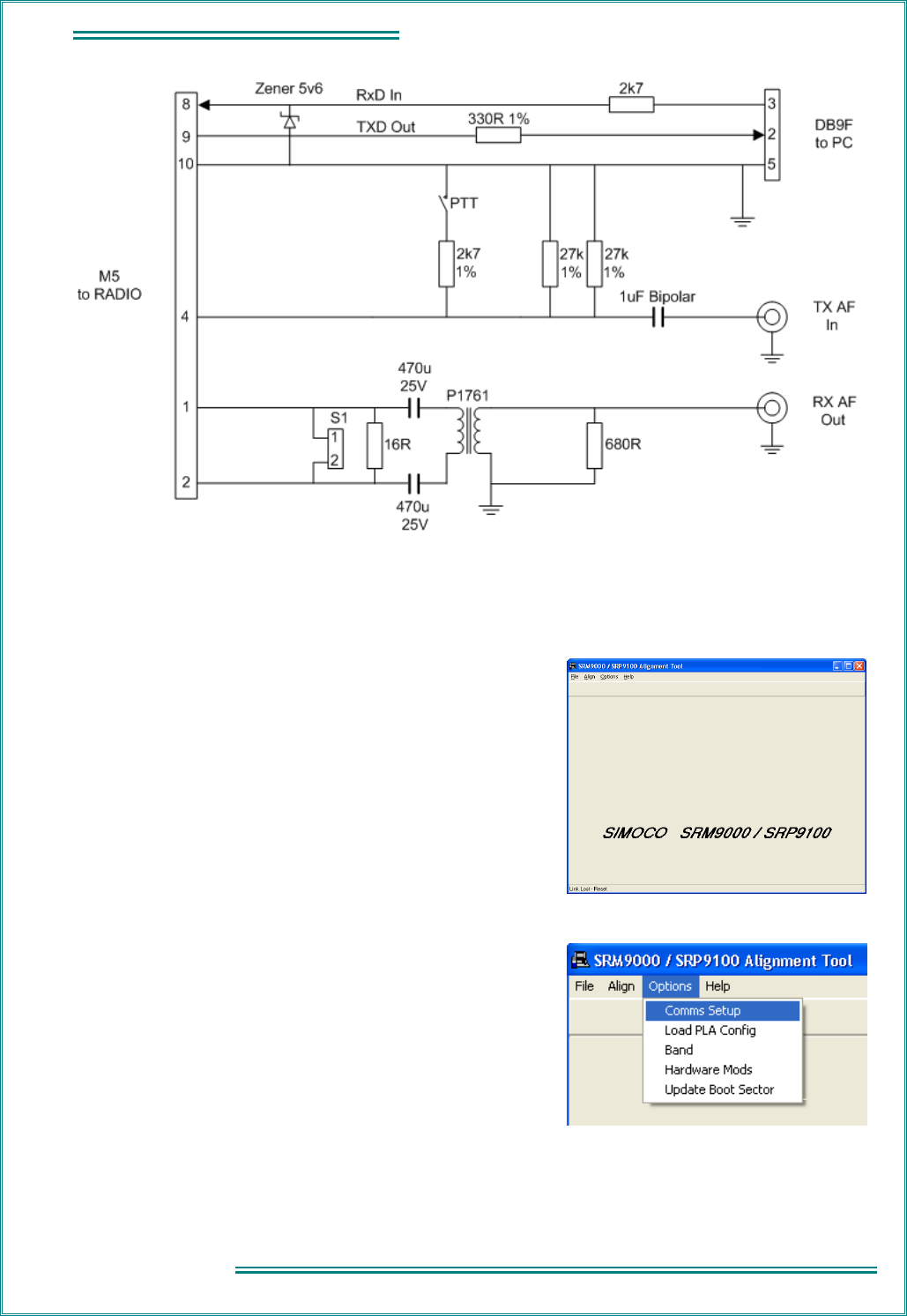
TNM-M-E-0023 SRP9170/80 Service Manual Issue 1.00
Page
5.3
5 - ALIGNMENT
Figure 5-2 SRP9170/80 Radio Test Interface Unit
5.2.1
COMMS Set up
1. Copy the SRP9170/80 Alignment Tool Computer Software
file to the PC hard drive and run the program.
The Alignment Tool Opening Menu is displayed.
2. Go to the Options menu and choose Comms Setup.
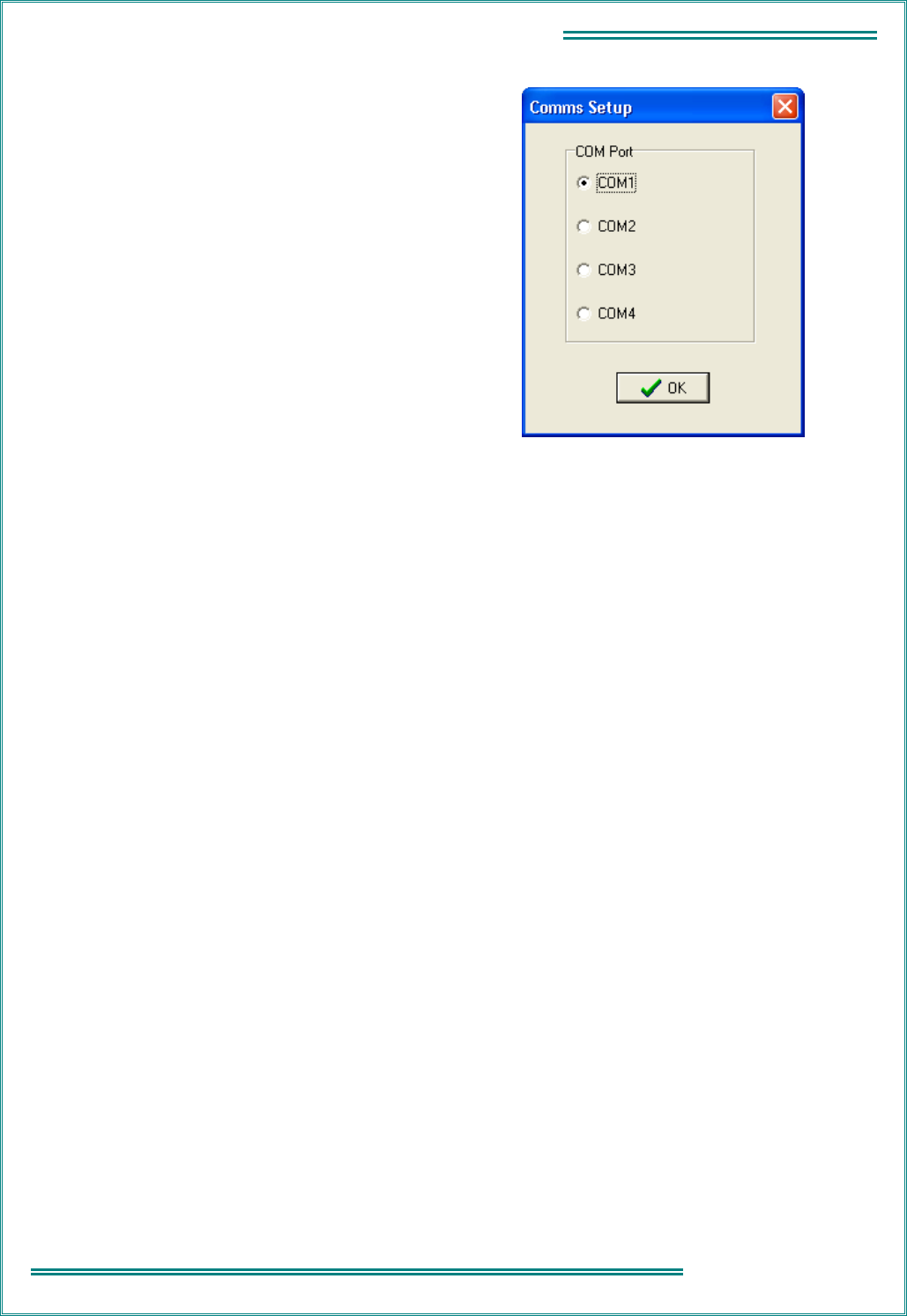
TNM-M-E-0023 SRP9170/80 Service Manual Issue 1.00
Page 5.4
5 - ALIGNMENT
3. The Comms Setup dialogue box is displayed.
Select the Comms Port setting appropriate to the
configuration of your PC and choose
OK.
(Usually COM1).

TNM-M-E-0023 SRP9170/80 Service Manual Issue 1.00
Page
5.5
5 - ALIGNMENT
5.2.2
Radio Preparation
Radio parameters need to be aligned sequentially as detailed in this procedure.
1. At the Opening Menu, select the Align Menu
and choose Prepare/Read Radio.
2. The WARNING is displayed.
Choose No if you want to save the
configuration and use the FPP software to
read and save the data to a file.
Choose Yes if you want to proceed and go to
step 3.
3. The radio alignment data is read (indicated by
percentage bar) and stored.
The test alignment data is downloaded into
the radio.
Note: In test alignment mode the radio is configured only for 12.5 kHz channel spacing, therefore all
alignment is carried out at 12.5 kHz settings unless otherwise specified. When the radio is
configured with the FPP for other channel spacings, the deviation related levels are calculated on a
per channel basis by the radio software.
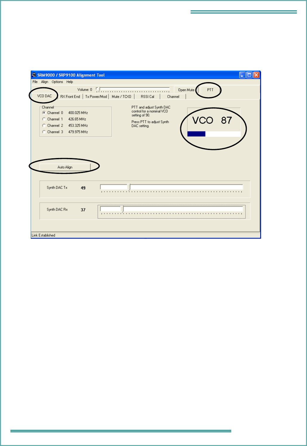
TNM-M-E-0023 SRP9170/80 Service Manual Issue 1.00
Page 5.6
5 - ALIGNMENT
5.2.3
Alignment Procedure
Radio alignment must be done in the sequence detailed in the following paragraphs. This alignment assumes
that the radio is functioning normally.
5.2.3.1 VCO DAC Alignment
1. Select the VCO DAC page.
2. Select Auto Align. The Synth DAC Rx slider will automatically adjust its value for each receiver
alignment frequency to set the VCO value between 85 and 95.
3. Select PTT and then select Auto Align. The Synth DAC Tx slider will automatically adjust its value for
each transmitter alignment frequency to set the VCO value between 85 and 95.
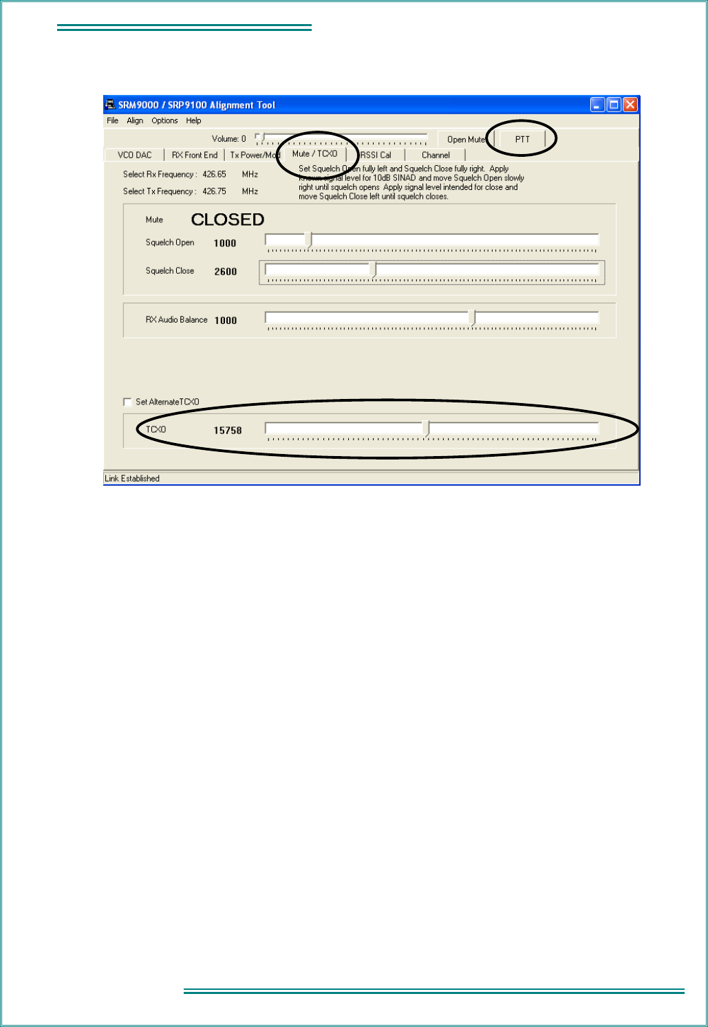
TNM-M-E-0023 SRP9170/80 Service Manual Issue 1.00
Page
5.7
5 - ALIGNMENT
5.2.3.2 TCXO Frequency Adjust
1. Select the Mute/TCXO page.
2. Select PTT.
3. Adjust the TCXO slider to ensure that the transmit frequency error is within 50 Hz for the selected
channel (to be measured on the RF Test Set frequency counter).
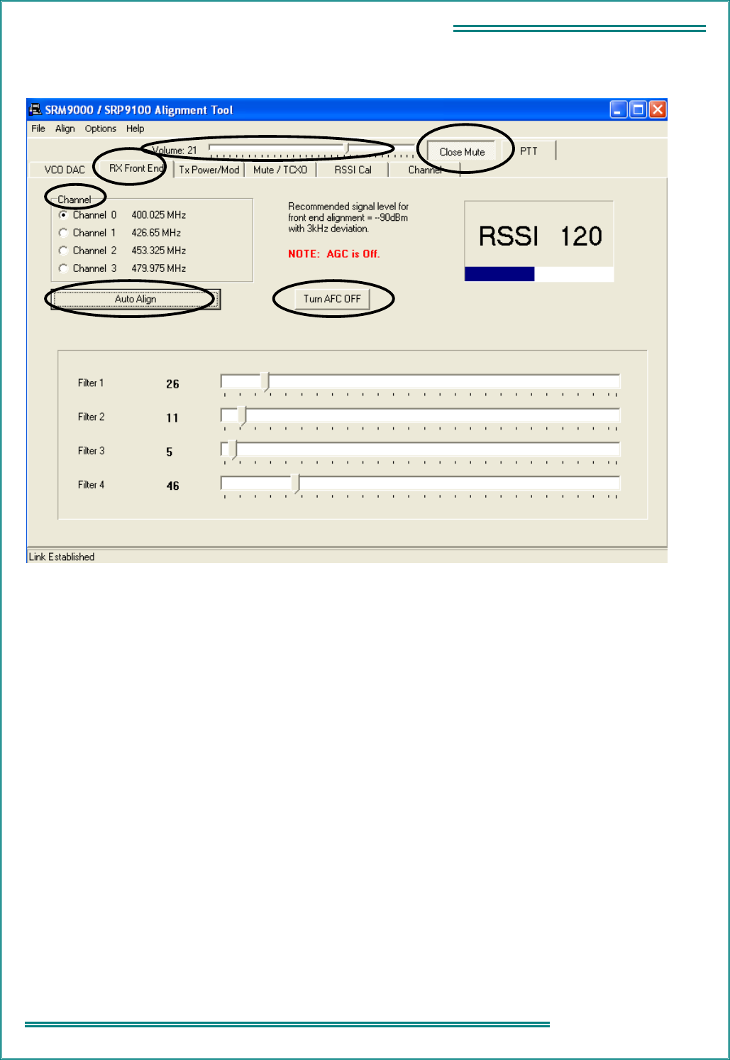
TNM-M-E-0023 SRP9170/80 Service Manual Issue 1.00
Page 5.8
5 - ALIGNMENT
5.2.3.3 Rx Front End
1. Ensure that the TCX0 Alignment has been done before proceeding with this section.
2. Select the RX Front End page.
3. Select Open Mute.
4. Set the Volume slider to 21. Speaker audio should now be visible on the CRO. If required readjust
the Volume slider to a suitable level.
5. Select Turn AFC ON.
6. Set the Signal Generator to the Channel 0 carrier frequency, with a 1000 Hz modulation signal, a
deviation of ± 3 kHz and an RF level of – 90 dBm.
7. Select Channel 0.
8. Select Auto Align. The front end will be tuned automatically and finish with an RSSI reading of
typically around 120.
9. Repeat Steps 6 to 8 for the three remaining Channels (1, 2, & 3).
10. Change deviation to 1.5 kHz.
11. Verify that the receiver sensitivity is better than - 117.5 dBm for 12 dB SINAD on all channels.
(Sensitivity is typically better than – 119 dBm).
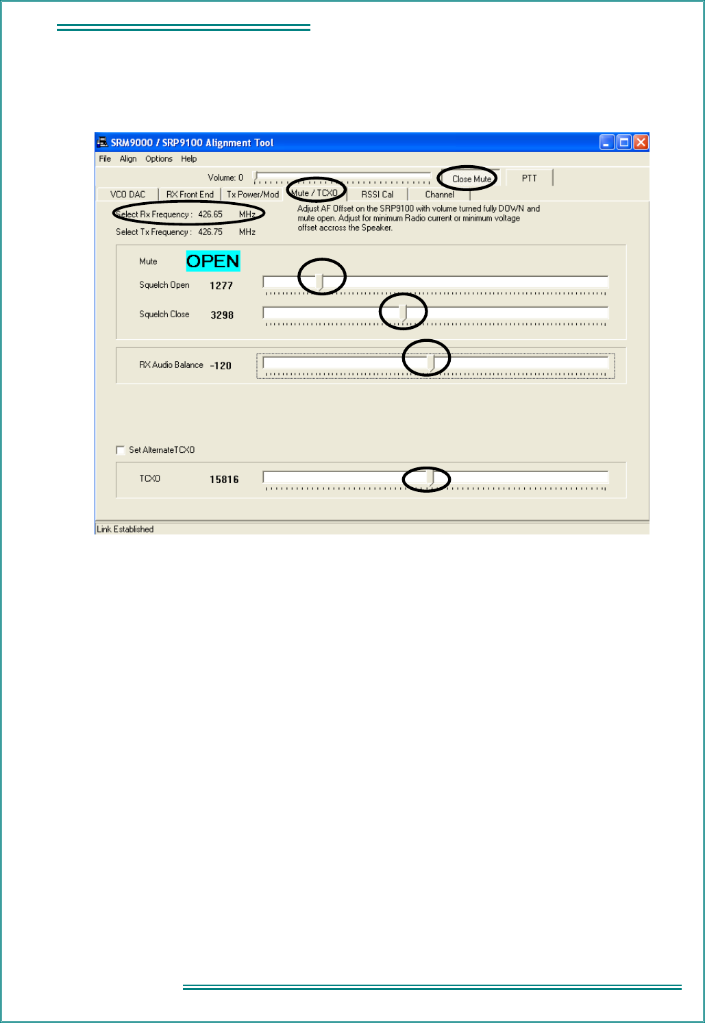
TNM-M-E-0023 SRP9170/80 Service Manual Issue 1.00
Page
5.9
5 - ALIGNMENT
5.2.3.4 Mute/Audio Balance Adjustment
Note. This adjustment has default setting of 1000 / 2600 and should not need changing except for specific
requirements.
Squelch Adjustment
RX Audio Balance Adjustment
1. Select the Mute/TCXO page and select Open Mute.
2. Set the RF signal generator to the receiver alignment frequency, and adjust the RF level such that
the desired mute opening SINAD (typically 10 dB SINAD) is achieved.
3. Select Mute Closed and remove the RF input from the radio.
4. Set the Squelch Open and Squelch Close sliders to the fully left position. This ensures the receiver
will be muted.
5. Set the Squelch Close slider to the fully right position.
6. Reconnect the RF input to the radio.
7. Adjust the Squelch Open slider to the right until the mute opens.
8. Reduce the Signal Generator output level by approximately 2 dB (or by an amount equal to the
desired mute hysteresis level).
9. Adjust the Squelch Close slider to the left until the mute closes.
10.
The mute should now open and close at the desired RF levels.
1. Unsquelch the radio and set the radio volume to minimum.
2. Monitor the DC voltage across the speaker or load. Adjust the Rx Audio Balance DAC to achieve a
minimum in the measured DC voltage (within 0 V ± 10 mV) and leave at this setting.
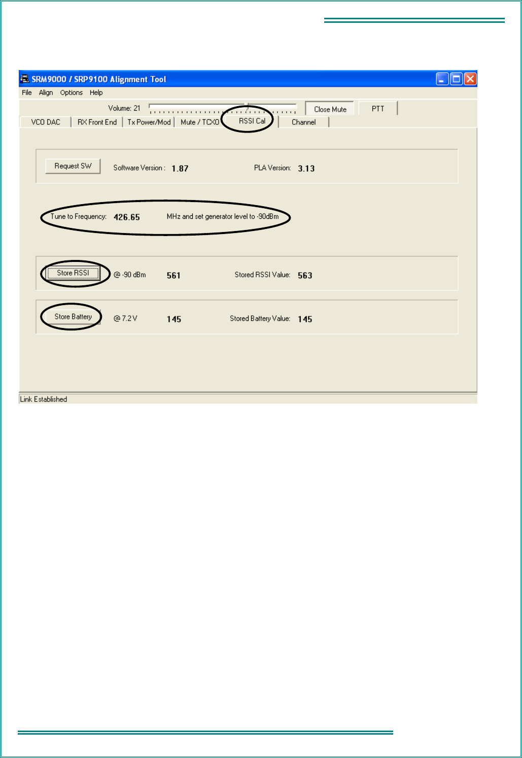
TNM-M-E-0023 SRP9170/80 Service Manual Issue 1.00
Page 5.10
5 - ALIGNMENT
5.2.3.5 RSSI
1. Select the RSSI Cal page.
2. Set the Signal Generator for a RF output level of – 90 dBm and 2 kHz deviation at the specified
frequency.
3. Activate the Store RSSI button.
The receiver RSSI threshold setting is calibrated.
4. Monitor the battery voltage at the simulated battery terminals with an accurate multimeter.
5. Adjust the power supply so that the voltage reads exactly 7.2 V ± 5 mV.
6. Click the Store Battery button to store the calibration.
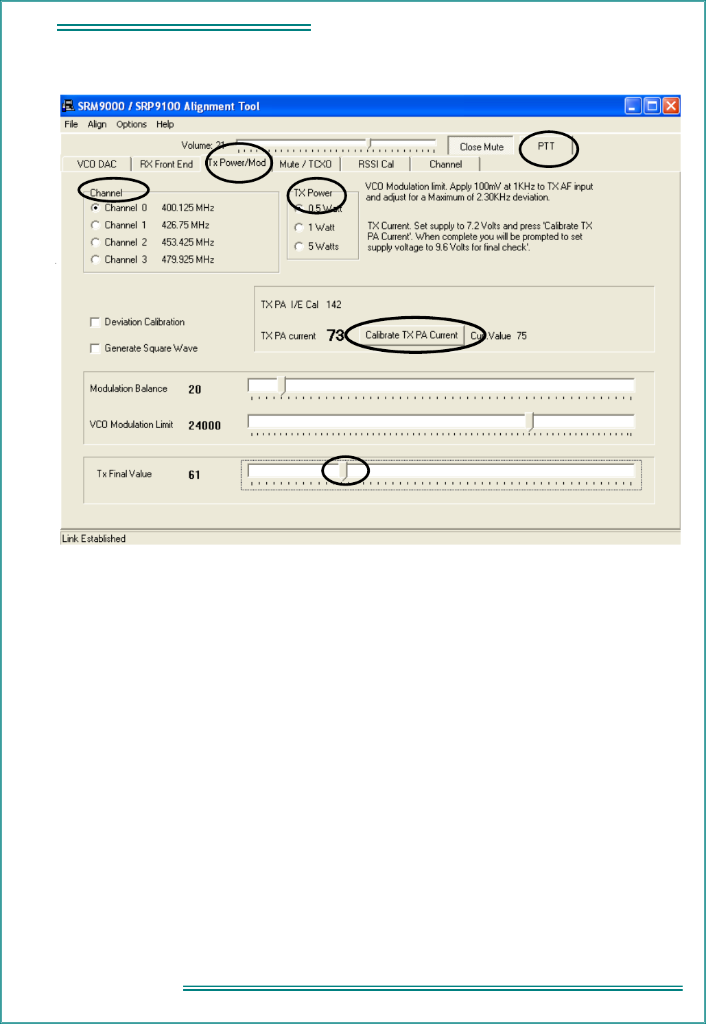
TNM-M-E-0023 SRP9170/80 Service Manual Issue 1.00
Page
5.11
5 - ALIGNMENT
5.2.3.6 Tx Power
1. Select Tx Power/Mod page.
2. Select Channel 0.
3. Select the 0.5 Watt power level.
4. Press the PTT button.
5. Adjust the Tx Final Value slider for a power output of 0.5 W.
6. Deselect PTT.
7. Repeat steps 3 to 6 for the three remaining channels (1, 2, and 3).
8. Select Channel 0.
9. Select the 1 Watt power level.
10. Press the PTT button.
11. Adjust the Tx Final Value slider for a power output of 1 W.
12. Deselect PTT.
13. Repeat steps 9 to 12 for the three remaining channels (1, 2, and 3).
14. Select Channel 0.
15. Select the 5 Watt power level.
16. Press the PTT button.
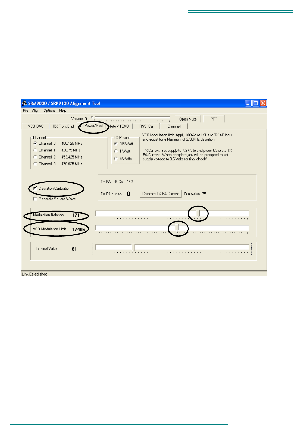
TNM-M-E-0023 SRP9170/80 Service Manual Issue 1.00
Page 5.12
5 - ALIGNMENT
17. Adjust the Tx Final Value slider for a power output of 5 W. Note that the supply current is less
than 2.5 A.
18. Deselect PTT.
19. Repeat steps 15 to 18 for the remaining 3 Channels (1, 2, and 3).
20. Press Calibrate TX PA Current button and follow the instructions to automatically set the
maximum current limit.
5.2.3.7 Modulation
1. Select Tx Power/Mod page.
2. Select Deviation Calibration.
3. Select Channel 0.
4. Select the 0.5 Watt power level.
5. Select PTT and, while viewing the de-modulated signal on the transceiver test set
oscilloscope, adjust the Modulation Balance slider for the best square wave symmetry.
Note. DC coupling is required on the scope for optimum setting accuracy.
6. Repeat steps 4 and 5 for the three remaining channels (1, 2, and 3).
7. Deselect Deviation Calibration.
8. Set the Tx Audio input signal from the audio generator to 1 kHz at 100 mV RMS.
9. Adjust the VCO Modulation Limit slider for a maximum peak deviation of ± 2.3 kHz.
10. Repeat step 9 for the three remaining channels (1, 2 and 3).
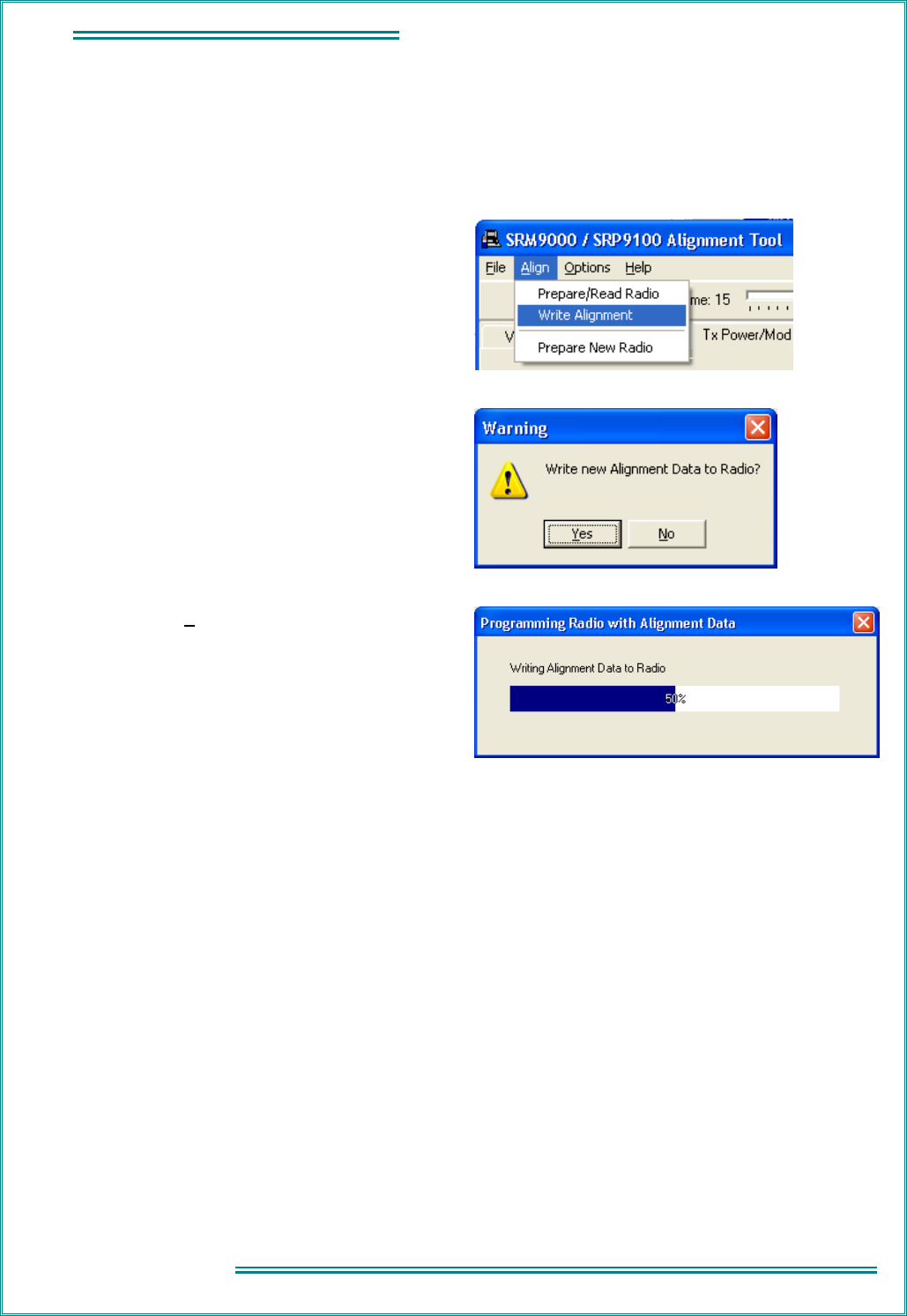
TNM-M-E-0023 SRP9170/80 Service Manual Issue 1.00
Page
5.13
5 - ALIGNMENT
11. Reduce the Tx Audio input level to 10 mV RMS and check that the deviation is within the range
± 1.25 kHz to ± 1.75 kHz for all channels.
5.2.3.8 Programming
When all channels have been aligned the radio is programmed with the new alignment data:
1. Select Align and choose Write Alignment.
2. A warning message is displayed.
3. Choose Yes.
New alignment data is written to the radio.
5.2.3.9 Customers Radio Configuration Data
If the Customers Radio Personality Data was saved as a separate file, use the FPP Programmer to write this
data to the radio.

TNM-M-E-0023 SRP9170/80 Service Manual Issue 1.00
Page 5.14
5 - ALIGNMENT
This Page Intentionally Left Blank

TNM-M-E-0023 SRP9170/80 Service Manual Issue 1.00
Page
6.1
6 – REPLACEABLE PARTS
6. REPLACEABLE PARTS
The parts listed in this section are considered to those most likely to need replacement due to physical
damage to the radio.
6.1 C
OMMON
P
ARTS
Ident Description Quantity per
Assembly
Part Number
SRP9180 PTT Button. 1 6102 310 0249
SRP9180 Function Button – A. 1 6102 310 0250
SRP9180 Function Button – B. 1 6102 310 0250
SRP9180 Speaker Clip. 1 6102 310 0242
SRP9180 Speaker Cloth. 1 6102 310 0279
SRP9180 Microphone Seal. 1 6102 310 0278
SRP9180 Volume Pot. 1 6102 141 0000
SRP9180 Channel Pot 16 Position. 1 6102 141 0001
SRP9180 Speaker Flex PCB. 1 6102 309 6245
SRP9180 Control Flex PCB. 1 6102 309 6242
SRP9180 Accessory Flex PCB. 1 6102 309 6244
SRP9180 Front Case Black Assy. 1 6102 350 1372
SRP9170 Front Case Black Assy. 1 6102 350 1371
SRP9180 LCD Dust Gasket. 1 6102 310 0261
SRP9180 Keymat. 1 6102 310 0253
SRP9170 Keymat. 1 6102 310 0319
SRP9180 Volume Knob Assy. 1 6102 350 1445
SRP9180 Front Case Label. 1 6102 310 026
SRP9170 Front Case Label. 1 6102 310 0320
SRP9180 Speaker. 1 6102 640 0007
MIC ELECTRET. 1 6102 640 0001
SRP9180 Graphics MMI Assy. 1 6102 350 1401
RETAINER MIC. 1 3513 905 6054
SEAL ACTUATOR. 5 3513 905 8179
SEAL LOUDSPEAKER. 1 3513 905 8180
SRP9180 LCD Lens. 1 6102 310 0252
6.2 A
CCESSORIES
Description Part Number
ACCESSORY CORD STRAIGHT (UNTERMINATED) SRP91X0. E-CAB-M5-S5.
OP13-50
ANTENNA HELICAL E0 BAND (66-88 MHz) SRP9100. PA-AHE0
ANTENNA HELICAL HIGH PERFORMANCE E0 BAND (66-88 MHz) SRP9100. PA-AHE0-HIGH
ANTENNA HELICAL AC BAND (136-174 MHz) SRP9100. PA-AHAC
ANTENNA HELICAL K1/KM BAND (174-245 MHz) SRP9100. PA-AHAK

TNM-M-E-0023 SRP9170/80 Service Manual Issue 1.00
Page 6.2
6 – REPLACEABLE PARTS
ANTENNA WHIP R1 BAND (335-375 MHz) SRP9100. PA-AWR1
ANTENNA HELICAL TU BAND (400-480 MHz) SRP9100. PA-AHTU
ANTENNA HELICAL UW BAND (440-520 MHz) SRP9100. PA-AHUW
ANTENNA WHIP TU BAND (400-480 MHz) SRP9100. PA-AWTU
ANTENNA WHIP UW BAND (470-520 MHz) SRP9100. PA-AWUW
BATTERY SRP9180 Li-ion 2200 mAh. PAR-9180BATL2x
EXTERNAL ANTENNA CONNECTOR. PA-CON
LEAD PROGRAMMING SRP9180. PAR-9180PRLDU

TNM-M-E-0023 SRP9170/80 Service Manual Issue 1.00
Page
A-A
APPENDIX A – ACCESSORY CONNECTOR
APPENDIX A - ACCESSORY CONNECTOR
The following table details the pin-out on the accessory connector.
Pin Signal Name Use Signal type Direction
1 Ext_Rx2 Balanced Audio Out (+). 10 Vp-p into 16 ohm To Accessory.
2 Ext_Rx1 Balanced Audio Out (-). 10 Vp-p into 16 ohm To Accessory.
3 B+ Battery Supply Voltage. 6.5 V to 8.4 V (68 ohm
resistor in series)
To Accessory.
4 Ext_Mod Multi-function.
Ext audio mod in:
Accessory sense voltage:
External modulation.
5 mV RMS nominal.
0 to 5 V DC sense.
To Radio.
5 Acc_Key2 PTT. Active low (ground). To Radio.
6 Acc_Key1 Accessory enabled. Active low (ground). To Radio.
7 0VA Ground. 0 V Ground.
8 RxD1_In Serial receive data. RS232 (- 12 V Mark, + 12 V
Space)
USB (2.8 V High, 0.8 V
Low)
TTL (+ 5 V High, 0 V Low)
To Radio.
9 TxD1_Out Serial transmit data
5 V supply output (100 mA
max.).
RS232/USB
5 V (continuous TTL
space).
To Accessory.
10 N/C Not used. NA
11 N/C Not used. NA
12 N/C Not used. NA
13 0VA Ground. Ground.

TNM-M-E-0023 SRP9170/80 Service Manual Issue 1.00
Page A-
B
APPENDIX A –
ACCESSORY CONNECTOR
This Page Intentionally Left Blank
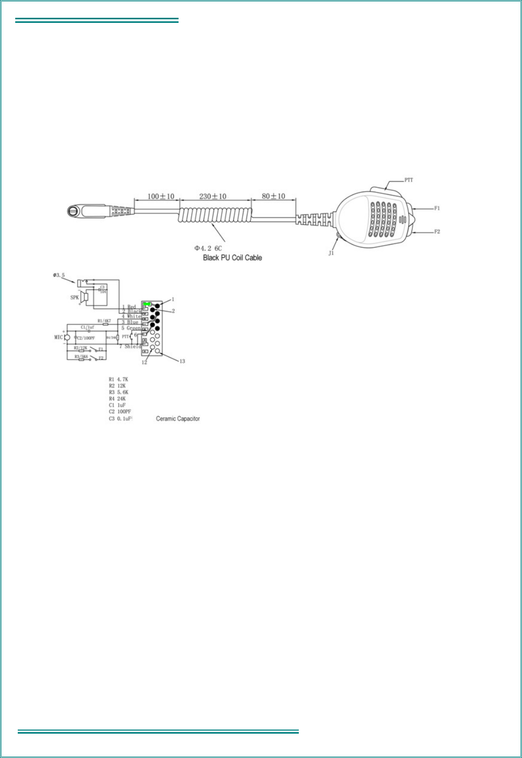
TNM-M-E-0023 SRP9170/80 Service Manual Issue 1.00
Page B-
B
APPENDIX B – ACCESSORIES
APPENDIX B - ACCESSORIES
Lapel Speaker Microphone
PAR-9180LMS2
Figure B-1 Lapel Speaker/Microphone
Introduction
The lapel loudspeaker/microphone is a robust, lightweight, unit with an integral press-to-talk (PTT) switch and
a headset socket. The unit connects to the portable radio via a 450 mm curly cable (un-stretched) fitted with
a M5 type plug.
Specification
Microphone
Maximum circuit current: 10 mA
Type: Electret.
Impedance: 2 kΩ (nominal)
Sensitivity: – 64 dB ± 4 dB at 1 kHz (0 dB = 1 V/µbar)
Sensitivity variation relative to 1 kHz over
frequency range:
Less than + 10 dB, – 2 dB, 300 Hz to 4 kHz
PTT switch: Push-to-Talk.

TNM-M-E-0023 SRP9170/80 Service Manual Issue 1.00
Page B-
C
APPENDIX B – ACCESSORIES
DC voltage overshoot during switching periods: Within 2% of nominal voltage.
Loudspeaker
Impedance: 16 Ω ± 2 Ω
Power rating: 0.3 W nominal, 0.5 W maximum.
Headset socket: 3.5 mm - loudspeaker disconnected when jack inserted.
Environmental
Operating temperature range: – 20 °C to + 55 °C
Storage temperature range: – 40 °C to + 80 °C
OPERATION
Ancillary Type
R4 identifies to the radio that the accessory is a Lapel Speaker/Microphone.
Microphone
The microphone connects to the radio via pin 4 and is powered via pin 3 on the M5 plug.
When the Lapel Speaker/Microphone is connected to the radio, the radio’s internal microphone is disabled.
Loudspeaker
The loudspeaker connects to the radio via pin 1 and pin 2 of the M5 plug.
When the Lapel Speaker/Microphone is connected to the radio, receive audio is routed to the accessory
loudspeaker, the radio’s loudspeaker is disabled.
The Lapel Speaker/Microphone supports the use of a remote headset.