Simoco Wireless Solutions SRP9170UW UHF PORTABLE TRANSCEIVER User Manual USERS MANUAL
Simoco Australasia Pty Ltd UHF PORTABLE TRANSCEIVER USERS MANUAL
USERS MANUAL
SRP9180 / SRP9170 P25
Portable Radio
P25 User Manual
TNM-U-E-0091 V1.4a
August 2009

SRP9170/80 P25 Portable Radio – User Manual
© ComGroup Australia 2010 Page 2 TNM-U-E-0091 1.4a
Associated Documentation
The following documentation is available for use with the SRP9180 series of products:
TNM-U-E-0088 SRP9180 PMR Brief User Guide
TNM-U-E-0089 SRP9180 PMR User Manual
TNM-U-E-0090 SRP9180 MPT1327 User Manual
TNM-U-E-0095 SRP9180 P25 Brief User Guide
TNM-U-E-0102 SRP9180 Brief User Guide (General)
To order copies of any of the above publications, or any other Simoco product, contact
Comgroup Australia on +61 3 9730 3800 or send a Fax on +61 3 9730 3968.
The Simoco web site also has a comprehensive list of documentation available for download.
www.simoco.com.au
About This Document
This publication is copyright and no part may be reproduced without prior permission of
ComGroup Australia.
Due to our policy of continuous improvement to our products and services, technical
specifications and claims, correct at time of publication, may be subject to variation without
prior notice.
ComGroup Australia has endeavoured to ensure that the information in this document is
fairly and accurately stated, but does not accept liability for any errors or omissions.
Conventions
Where the word “generally” or “may” is used to describe a facility, this operation is an option
that may be enabled with the FPP.
In some cases, key functions will be determined by the customer configuration, so when a
key function is referred to in these instructions, the function may be assigned to another
physical location than designated here.
References to the SRP9180 also apply to the non-keypad version (SRP9170) except where
keypad operation is described.

SRP9170/80 P25 Portable Radio – User Manual
© ComGroup Australia 2010 Page 3 TNM-U-E-0091 1.4a
General Safety
1. Do not operate your portable radio, without a handsfree kit, whilst driving a
vehicle.
2. Do not operate your radio in an explosive atmosphere – unless the radio’s level
of IECEx approval is approved for use in that atmosphere.
Obey the 'Turn Off Two-way Radios' signs where these are posted, e.g. on a
petrol station forecourt.
3. Do not dispose of batteries in a fire.
IECEx Intrinsically Safe Radios
Radio models approved for use in hazardous environments according to the IECEx Scheme
are marked with an approval number.
Refer to the label on the radio for the IECEx compliance level.
The following MUST be observed to maintain the IECEx protection rating:
• Use only approved SIMOCO battery, part number PAR-9180BATL2i or PAR-9180BATL3i.
• Battery charging must only be carried out in non-hazardous areas, using an approved
battery charger.
• Metal belt clips must NOT be used in hazardous areas.
• It is a requirement that when the radio is used in a hazardous area that either the SRP9180
Accessory Cover Assy (6102 350 1446) or an approved Simoco IECEx accessory is fitted
(refer Section 7 for list of approved accessories).
• Approved accessories may only be connected and disconnected outside hazardous areas.
• Prior to use in a hazardous area, inspect the radio and accessories for signs of damage.
Any visible signs of damage to the radio or accessories may compromise the integrity and
safety of the radio. A damaged radio or accessories must be repaired or replaced prior to use
in a hazardous area.
• Incorrect storage, handling or operation of the radio and accessories, as specified in
Simoco published User Guides and Service Manuals, may compromise the safety and
integrity of the radio and/or accessories.
• Approved labels stating the IECEx rating level must be on the radio and accessories, and
be legible, before their use in a hazardous area.
• Servicing and upgrades of IECEx approved Intrinsically Safe radios and accessories must
only be carried out by Simoco IECEx Intrinsically Safe trained staff, at locations that have
been IECEx approved. Please contact the Simoco Help Desk on 1300 363 607 for your
nearest approved Service Department.
• Substitution of parts or accessories will void the equipments’ IECEx Intrinsic Safety rating.

SRP9170/80 P25 Portable Radio – User Manual
© ComGroup Australia 2010 Page 4 TNM-U-E-0091 1.4a
Hints for Using the Radio
When transmitting, hold the radio a few centimetres from your mouth and speak across it,
rather than into it. The microphone is located near the bottom right hand corner of the
portable radio’s speaker grille.
Keep the length of your conversation to a minimum to conserve battery life.
When it is possible to move location, avoid making calls from known poor signal-strength
areas such as the radio systems fringe areas (limit of range) or from screened or
shadowed areas, e.g. an underground car park or underpass.

SRP9170/80 P25 Portable Radio – User Manual
© ComGroup Australia 2010 Page 5 TNM-U-E-0091 1.4a
CONTENTS
1 INTRODUCTION ................................................................................................. 8
1.1 Overview...................................................................................................... 8
1.2 Configuration .............................................................................................. 8
1.3 Modes of SRP9180 P25 Operation ............................................................ 8
2 CONTROLS......................................................................................................... 9
3 MENU SYSTEM................................................................................................. 11
3.1 Menu Navigation ....................................................................................... 12
4 MENU SCREENS .............................................................................................. 14
4.1 Channel Screen......................................................................................... 14
4.2 Menus ........................................................................................................ 16
4.2.1 Zone........................................................................................................ 16
4.2.2 Squelch ................................................................................................... 18
4.2.3 Mute Adjust / Monitor (Analogue Channels)............................................ 19
4.2.4 Phonebook .............................................................................................. 20
4.2.5 Phonebook Edit....................................................................................... 22
4.2.6 User Options ........................................................................................... 25
4.2.7 Contrast................................................................................................... 26
4.2.8 Alert Volume............................................................................................ 26
4.2.9 Radio Info................................................................................................ 27
4.2.10 Mode ....................................................................................................... 29
4.2.11 RSSI........................................................................................................ 29
4.2.12 Crypto...................................................................................................... 31
4.2.13 Setup....................................................................................................... 31
4.2.14 Stored Calls............................................................................................. 32
4.2.15 Messages................................................................................................ 33
4.2.16 Scan Edit Menu....................................................................................... 42
4.2.17 No Menu.................................................................................................. 44
5 COMMON FUNCTIONS AND FACILITIES ....................................................... 45
5.1.1 Switch-On/Switch-Off .............................................................................. 45
5.1.2 Default Screen –Trunked Mode .............................................................. 45
5.1.3 Volume Adjustment ................................................................................. 45
5.1.4 Selecting Channels ................................................................................. 46
5.1.5 Selecting Zones ...................................................................................... 46
5.1.6 Receiving (Single Channel Screen) ........................................................ 46
5.1.7 Received Individual Calls ........................................................................ 46
5.1.8 Stored Calls Screen ................................................................................ 47
5.1.9 Received Call Pop-Up Menu ................................................................... 47
5.1.10 Transmitting ............................................................................................ 48
5.1.11 Scan/Vote Functions ............................................................................... 49
5.1.12 Keypad Lock ........................................................................................... 50
5.1.13 Encryption ............................................................................................... 50
5.1.14 Emergency Alarm.................................................................................... 51

SRP9170/80 P25 Portable Radio – User Manual
© ComGroup Australia 2010 Page 6 TNM-U-E-0091 1.4a
6 SPECIAL FUNCTION KEYS ............................................................................. 52
6.1 Alarm ......................................................................................................... 52
6.2 Announce .................................................................................................. 52
6.3 Channel Up and Down.............................................................................. 52
6.4 Crypto ........................................................................................................ 52
6.5 DTMF Send 1/2 (P25 Analogue) .............................................................. 52
6.6 Key Lock.................................................................................................... 52
6.7 Low Power................................................................................................. 53
6.8 Menu .......................................................................................................... 53
6.9 Mode .......................................................................................................... 53
6.10 Mute........................................................................................................ 53
6.11 Reset ...................................................................................................... 53
6.12 Scan ....................................................................................................... 53
6.13 Scan Edit................................................................................................ 54
6.14 Scrambler (P25 Analogue).................................................................... 54
6.15 Skip ........................................................................................................ 54
6.16 Squelch .................................................................................................. 54
6.17 Talkaround............................................................................................. 54
6.18 Zone ....................................................................................................... 54
7 ACCESSORIES................................................................................................. 55
7.1 Lithium Ion Battery (PAR-9180BATL2x).................................................. 55
7.2 Lithium Ion Battery (PAR-9180BATL2).................................................... 55
7.3 Lithium Ion Battery (PAR-9180BATL3x).................................................. 55
7.4 Lithium Ion Battery (PAR-9180BATL3).................................................... 55
7.5 Single Pocket Charger (PAR-9180CRG1)................................................ 55
7.6 Two Pocket Charger (PAR-9180CRG2) ................................................... 55
7.7 Six Pocket Charger (PAR-9180CRG6)..................................................... 55
7.8 Vehicle Mounted Charger (PAR-9180CRGV) .......................................... 55
7.9 Lightweight Carry Case (PAR-9180CLBC2)............................................ 55
7.10 Lightweight Carry Case (PAR-9180CLBC3) ........................................ 55
7.11 Heavy Duty Carry Case (PAR-9180CHSM) .......................................... 55
7.12 Lightweight Lapel Function Speaker Microphone (PAR-9180LMS2) 55
7.13 Four Function Speaker Microphone (PAR-9180LMS4) ...................... 55
7.14 Four Function Antenna Speaker Microphone (PAR-9180LMR4)....... 55
7.15 GPS Microphone (PAR-9180LMGM) .................................................... 55
7.16 Earpiece (PA-LMEP8)............................................................................ 56

SRP9170/80 P25 Portable Radio – User Manual
© ComGroup Australia 2010 Page 7 TNM-U-E-0091 1.4a
7.17 Programming Lead (MAR-9180PRLDU................................................ 56
7.18 Belt Clip (PAR-9180CLIP) ..................................................................... 56
7.19 Stud Mount (PAR-9180STUD)............................................................... 56
8 ALERT TONES AND MESSAGES.................................................................... 57
9 GLOSSARY....................................................................................................... 58
10 COMPLIANCE WITH RF ENERGY EXPOSURE GUIDELINES (UNITED
STATES AND CANADA) ......................................................................................... 60

SRP9170/80 P25 Portable Radio – User Manual
© ComGroup Australia 2010 Page 8 TNM-U-E-0091 1.4a
1 INTRODUCTION
1.1 OVERVIEW
The Simoco SRP9180 Series Radios are a family of versatile Digital Signal Processor (DSP)
controlled, software-defined two-way portable radios.
This User Manual describes the operation of the APCO P25 Standard compliant Portable
Radio.
The SRP9180 P25 Radio may be customised to your operational requirements using the
Field Personality Programmer (FPP). Your Simoco representative can help in programming
your radio facilities to meet your present and future requirements.
1.2 CONFIGURATION
The SRP9180 P25 Radio must be configured using the P25 Field Personality Programmer
(FPP) prior to operation. The configuration process defines the radio channels, signalling and
other settings so that the radio will operate with your system.
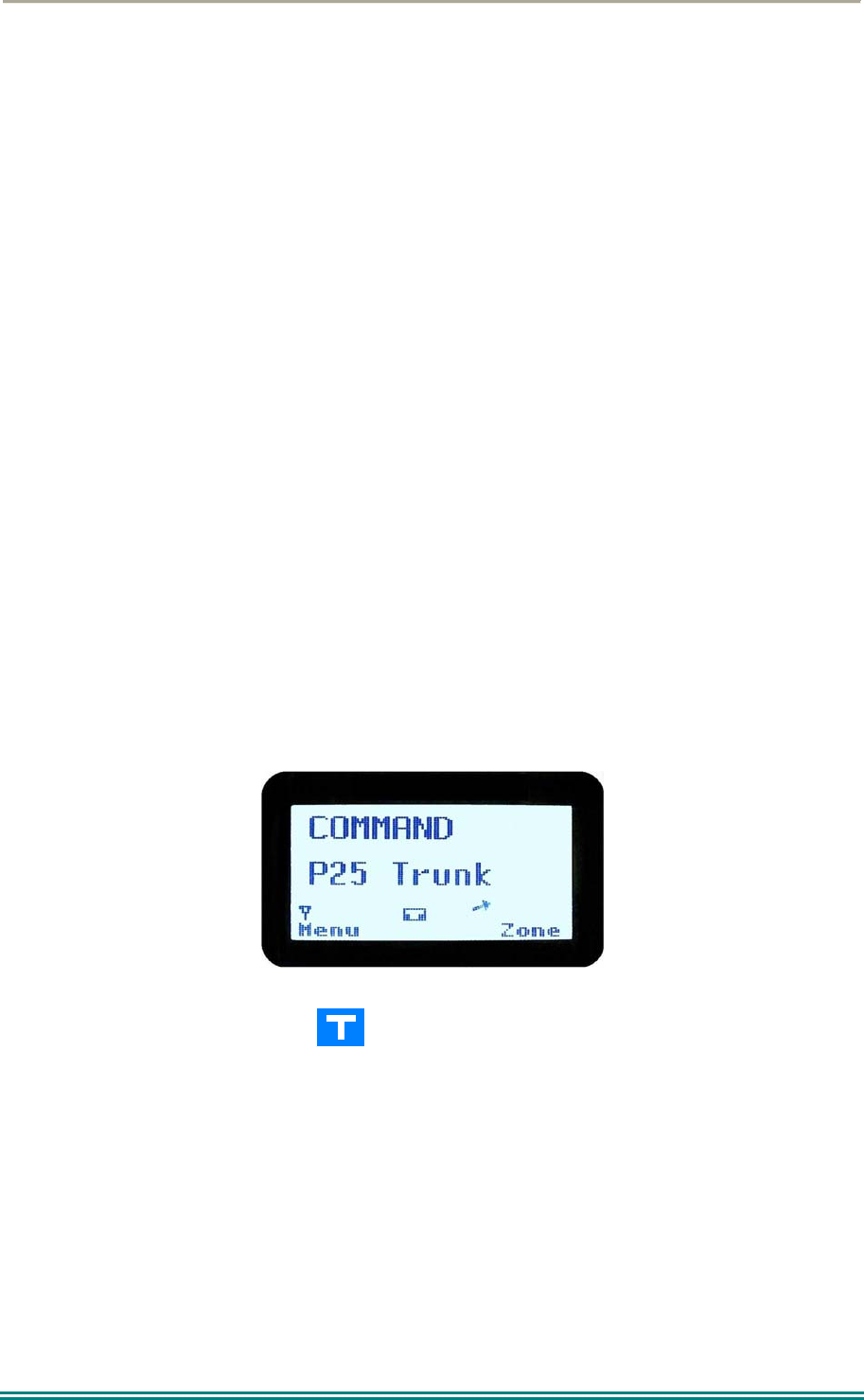
1.3 MODES OF SRP9180 P25 OPERATION
The SRP9180 P25 Radio operates in Analogue FM, P25 Conventional Digital and P25
Trunked Digital modes.
Radio Channels are organised in groups of up to 250 per zone. Up to 64 zones may be
defined.
Generally, zones can be programmed with channels belonging to common function groups.
A radio channel can be defined as either Analogue, a Conventional P25 Channel or a
Trunked P25 talkgroup. A Zone may contain a mix of Channel types.
SRP9170/80 P25 Portable Radio – User Manual
© ComGroup Australia 2010 Page 9 TNM-U-E-0091 1.4a
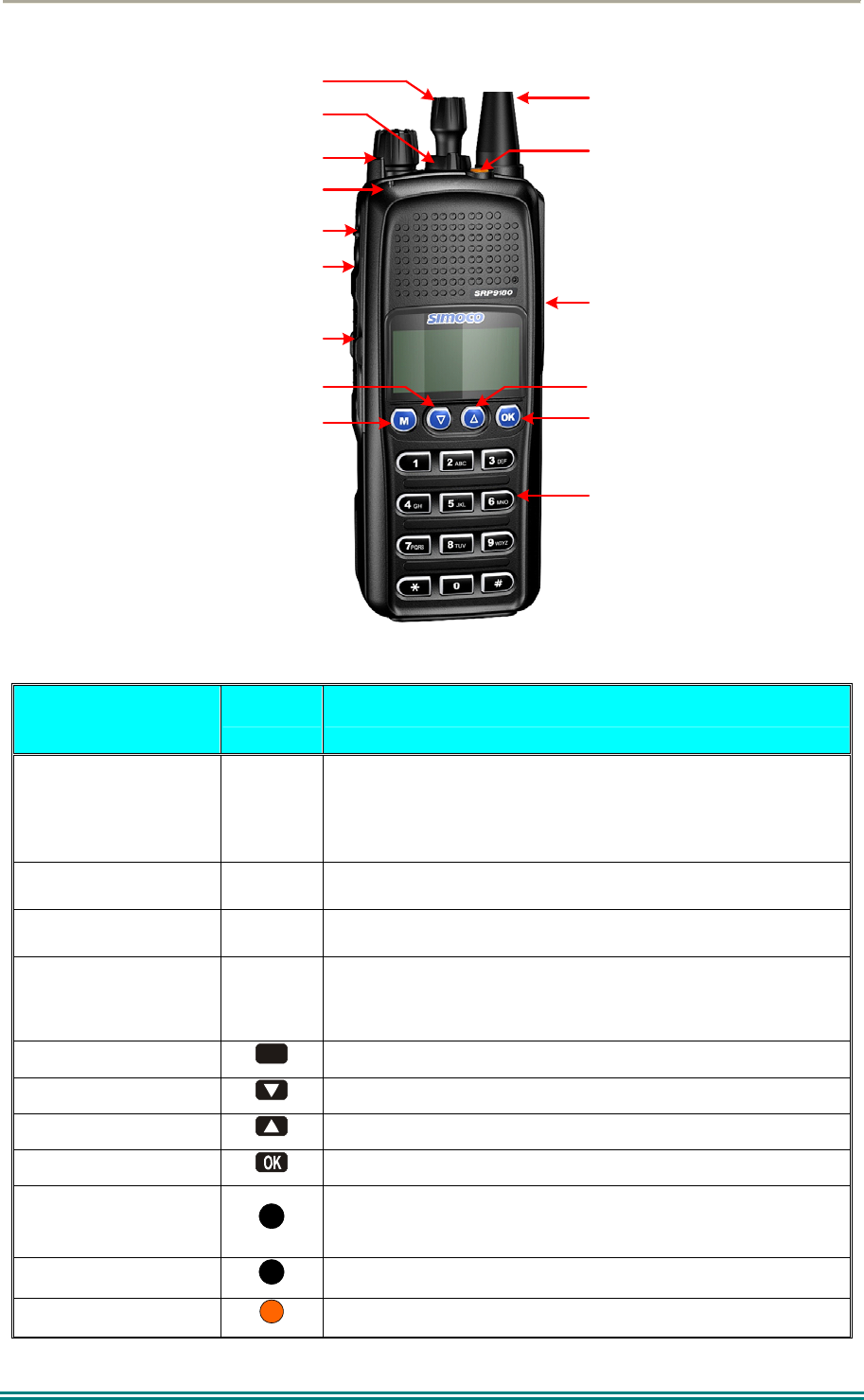
2 CONTROLS
Accessory
Connector
Function #7
Selector Switch
ABC Switch
On/Off Volume
PTT
Function #5
Function #6
Function #2
Function #1
Function #3
Function #4
Antenna
Keypad
Indicator LED
Figure 1 – SRP9180 Portable Key Layout
SRP9180
Key/Control
Label Function
On/Off / Volume
The radio is turned on by rotating the volume knob
clockwise, and turned off by rotating it anti-clockwise.
Turning the knob clockwise increases volume.
Selector Switch Rotate the switch to select the desired channel.
ABC Switch Programmer configurable function switch.
PTT
Push-to-Talk. Hold the radio 10cm from the mouth.
Press and hold the PTT switch and speak. Release to
listen.
Function Key F1
M
Programmable Function key. Default – Menu Select.
Function Key F2 Programmable Function key. Default – Channel Down.
Function Key F3 Programmable Function key. Default – Channel Up.
Function Key F4 Programmable Function key. Default – OK.
Function Key F5
Programmable Function key.
Function Key F6 Programmable Function key. Default – Reset / Cancel.
Function key F7 Programmable Function key. Default – Alarm.

SRP9170/80 P25 Portable Radio – User Manual
© ComGroup Australia 2010 Page 10 TNM-U-E-0091 1.4a
SRP9180
Key/Control
Label Function
Keypad
1 2 3
4 5 6
7 8 9
* 0 #
Keypad can be used to select a Channel or Special
Function.
E.g. 12# will select channel 12.
Indicator LED Function
Green
Green LED when receiving a signal.
Red
Red LED when the radio is transmitting.

SRP9170/80 P25 Portable Radio – User Manual
© ComGroup Australia 2010 Page 11 TNM-U-E-0091 1.4a
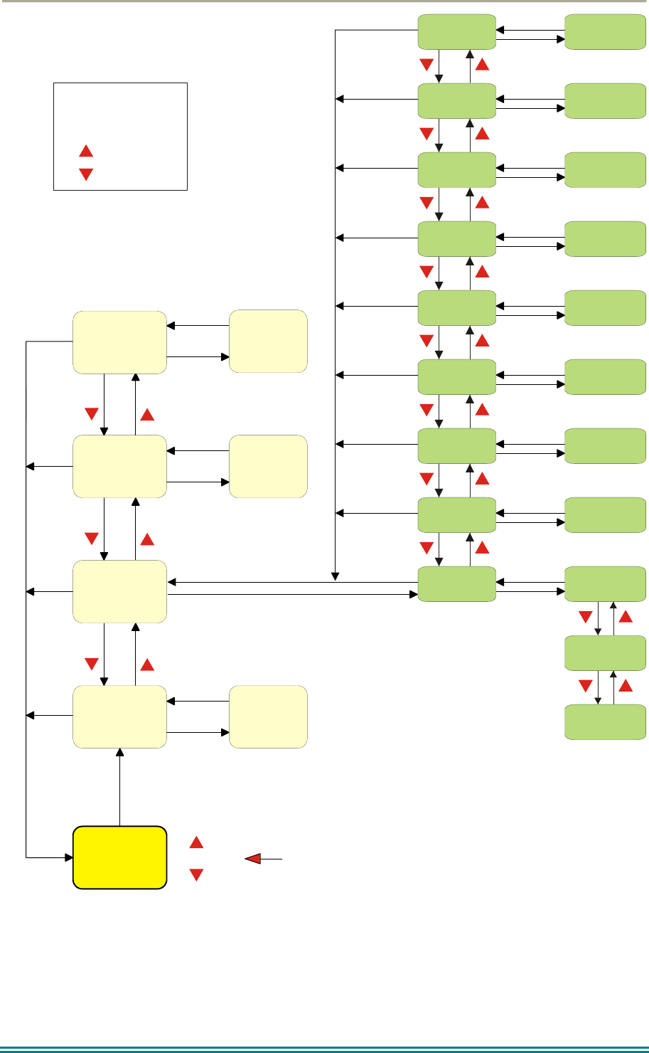
3 MENU SYSTEM
The SRP9180 P25 portable radio uses a menu structure for access to all of the radio
features and functions. The structure of the menu can be programmed to meet the specific
needs of individual customers.
Figure 2 illustrates the menu structure of the radio. Note that the order and presence of each
menu is determined by the configuration of the radio programmed by the Field Programmer.
Possible Menu entries are:
Zone (usually the first menu, as accessed often)
Squelch
Mute Adjust (FM) / Monitor (Digital)
Phonebook
Phonebook Edit
User Options
Contrast
Alert Volume
Radio Info
Mode
RSSI
Crypto
Setup
Stored Calls
Messages
Scan Edit
No Menu
To assist the user in menu key selection, a soft menu label may appear above the function
keys. The label shows the user the current function for that key which may change between
different menus.
Programming of menus is a configuration task normally performed by the system manager
using the FPP software.

SRP9170/80 P25 Portable Radio – User Manual
© ComGroup Australia 2010 Page 12 TNM-U-E-0091 1.4a
3.1 MENU NAVIGATION
Pressing the “M” key selects Menu mode from the main Channel Screen. Once in menu
mode, the ▼ and ▲ keys cycle through the menus.
To exit Menu mode, press the “M” key again or the Menu timeout will exit automatically.
Generally, pressing “M” key while in a menu backs up to the next highest level of menu and
the “OK” key selects the menu screen.
The ▼ and ▲ keys are used to navigate through a list of options such as channels, or
increase/decrease a value.
When the Menu key is first pressed, the numeric keys become short cut keys to functions.
Numeric keys can be programmed (using FPP) with functions i.e. Scan.
To access this, you can press the “M” or menu key from the channel screen and then the
numeric key assigned to that function.
SRP9170/80 P25 Portable Radio – User Manual
© ComGroup Australia 2010 Page 13 TNM-U-E-0091 1.4a
Normal
Channel
Screen
Zone Select
Menu #1
Setup Menu
(Optional)
(Optional)
Menu #2
Menu #3 Menu #3
Menu #x Menu #x
Select
Zone
ENTRY POINT = Default Screen
Channel
Note:
Example Menus only shown.
P25 Conventional Menu rev1d
Other Menus may be configured with the FPP
Up Key
Down Key
Back Key
OK Key
Squelch
Mute
Adjust
SubMenu Selections
RSSI
Mode
Radio Info
Crypto Key
Alert
Volume
Contrast
User Options
Submenu
Submenu
Submenu
Submenu
Submenu
Submenu
Submenu
Submenu
Key Beeps
ON/OFF
Backlight
ON/OFF
(Other User
Menu items)
Back
OK
Menu
OK
OK
OK
OK
OK
OK
OK
OK
OK
BackBack
BackBack
BackBack
Back
Back
OK
BackBack
Back
OK
BackBack
Back
Back
OK
BackBack
Back
Back
OK
BackBack
BackBack
BackBack
Figure 2 - Menu Navigation
SRP9170/80 P25 Portable Radio – User Manual
© ComGroup Australia 2010 Page 14 TNM-U-E-0091 1.4a
4 MENU SCREENS
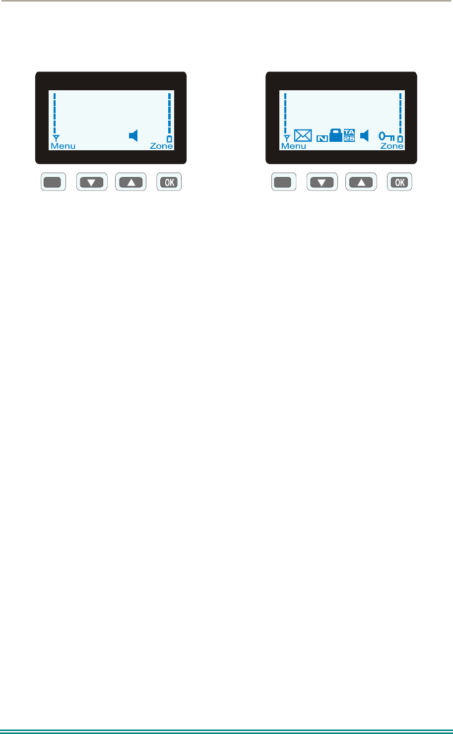
4.1 CHANNEL SCREEN
M
Special Ops
Zone 4
Typical Display
M
Icons
The Channel Screen shows the current channel and allows channel selection.
The Channel Name (top line) shows the text associated with the currently selected radio
channel.
The Zone Name (middle) shows the text associated with the currently selected radio zone.
The RSSI Bars indicate the signal strength of the current channel.
The Battery Bars indicate the battery charge level.
Pressing the “M” key enters the Menu mode.
The lower part of the screen is reserved for icons.
Radio channels may be configured with the Field Programmer as specific frequencies or as
auto scan types. When an auto scan channel is selected, it will immediately go into scan
mode. Selecting another non-autoscan channel will stop the scan.
If a radio channel is defined as a P25 Conventional Digital Channel, it will only receive P25
digital signals.
If a radio channel is defined as an Analogue FM channel, it will receive both P25 Digital* and
Analogue FM signals.
* When an Analogue FM channel is selected and in Monitor mode , all unencrypted digital
P25 traffic will be heard regardless of NAC or Talkgroup.
SRP9170/80 P25 Portable Radio – User Manual
© ComGroup Australia 2010 Page 15 TNM-U-E-0091 1.4a
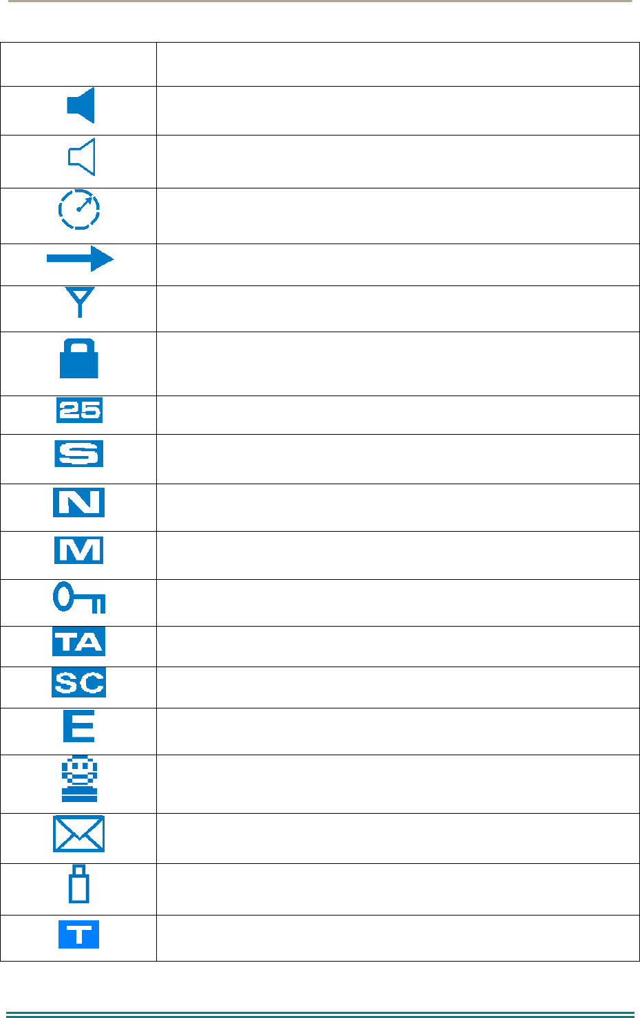
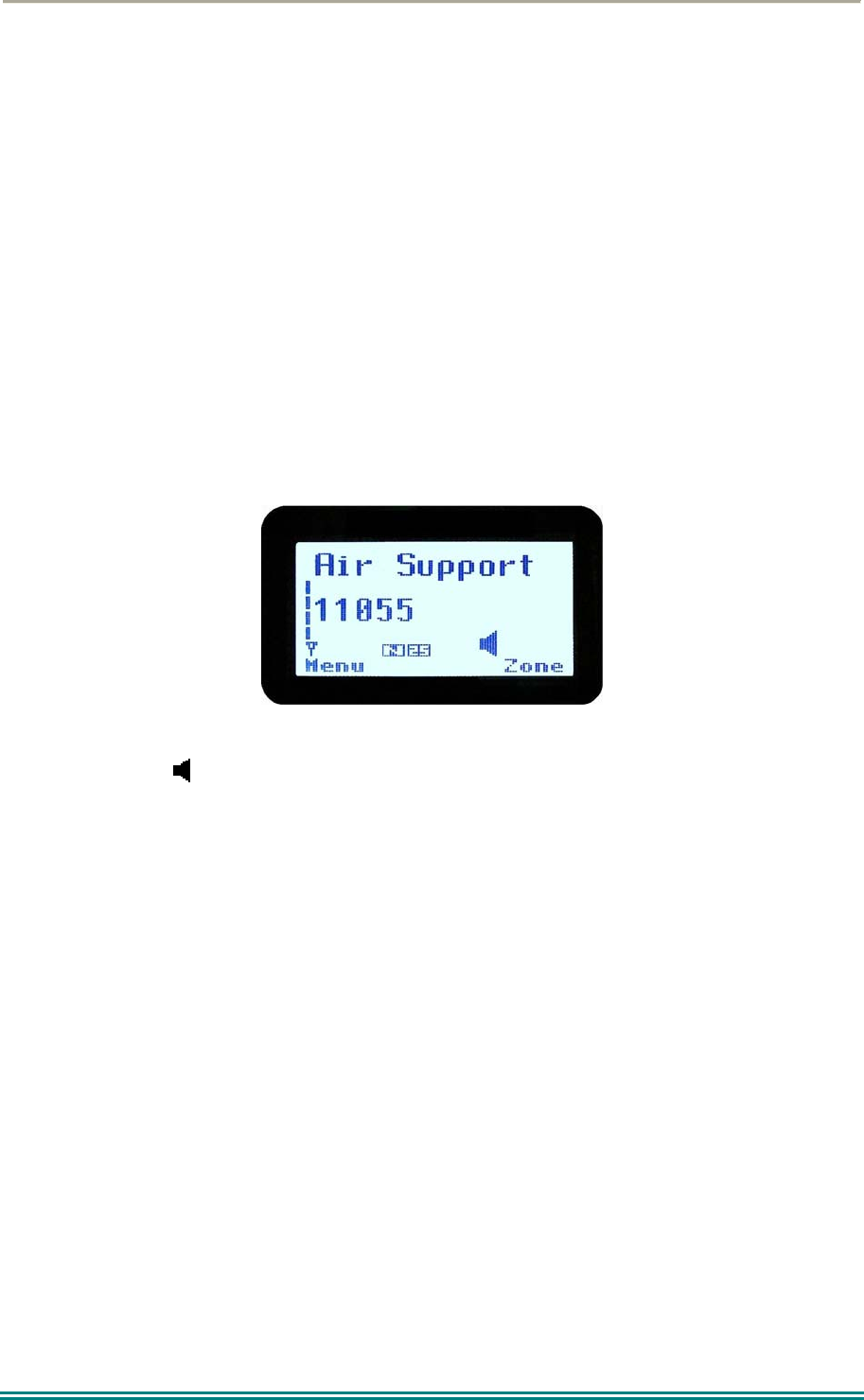
ICONS INDICATION
A filled speaker indicates that a signal is present and the audio can
be heard from the speaker.
The outline speaker icon indicates that a signal is present and the
radio is muted. This could be another user group, for instance.
Scan Indicator. When radio is on a scan channel and scanning, the
arrow will rotate.
Transmit Indicator.
Received Signal Strength Indication (RSSI). A stronger signal will
display more bars above the “antenna” icon.
Encryption Indicator. The icon is shown when the selected channel is
programmed for encryption. If an unencrypted signal is received, the
icon will be not be displayed.
25 = Digital Mode Indicator.
Selective Mute. Only radio signals specifically directed to the user or
the channel’s defined talkgroup will be heard on the speaker.
Normal Mute. Only radio signals from the users own network will be
heard on the speaker.
Monitor. All P25 digital radio signals on the channel will be heard.
All keys except PTT, or any function assigned as Alarm, will be
disabled. Press the OK key for 2 seconds to unlock all keys.
Talk Around enabled indicator. When shown, Talk Around is active.
Scrambler indicator (analogue only).
Emergency mode. Blinking icon indicates that the emergency key
has been pressed.
Individual Addressing Mode. When shown, the radio will transmit to
an individual address instead of a talkgroup.
Envelope icon. Indicates that a message(s) stored if icon steady,
icon flashes if unread message(s) stored.
Battery charge indicator. 6 vertical bars above the icon show the
battery state of charge.
Trunking mode. Icon is shown when a trunking system has been
selected.
SRP9170/80 P25 Portable Radio – User Manual
© ComGroup Australia 2010 Page 16 TNM-U-E-0091 1.4a
C
Connecting icon. Shown when a text message is being sent and the
connection is in progress.
! Connection Fail icon. Shown when a text message transmission has
failed.
* Radio has stopped on a scan channel.
4.2 MENUS
The menu structure on the SRP9180 is configurable using the Field Programmer. A system
administrator usually tailors the order and presence of the menu options to specific customer
requirements.
This section will describe all the possible menus.
Normally the menus are divided into two menu lists.
These are normally the Main menu list and the Setup menu list. Menu selections that are
not frequently accessed are normally put under the Setup menu list.
In the default configuration, the Main menu contains the Zone screen and a Setup screen.
This allows access to the second “Setup” menu level.
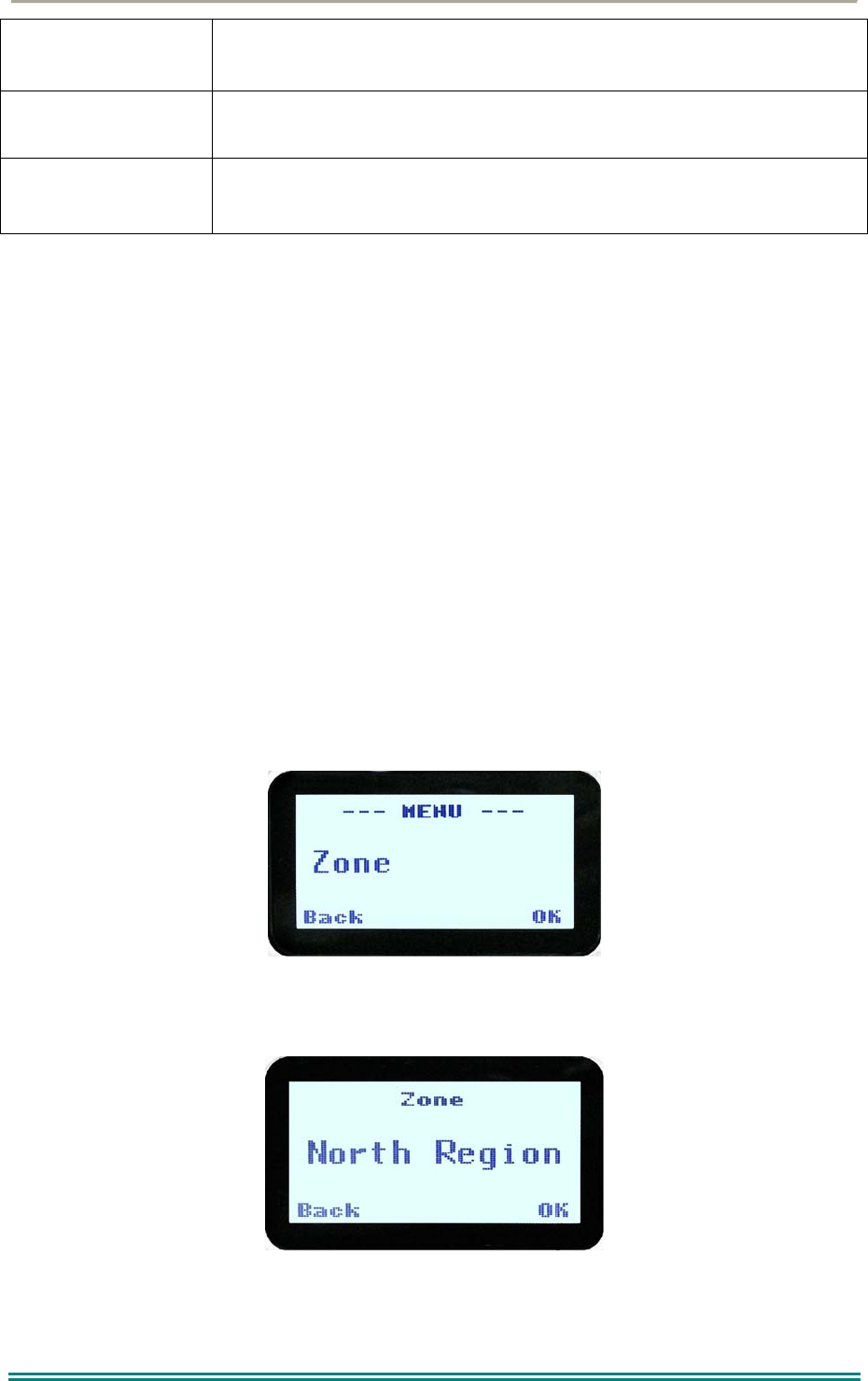
4.2.1 Zone
The Zone Screen is used for changing Zones. A Zone is normally defined as a group of radio
channels with a common operational role.
When the “Zone” menu option is displayed, press the “OK” key to enter the “Zone“ select
screen.

SRP9170/80 P25 Portable Radio – User Manual
© ComGroup Australia 2010 Page 17 TNM-U-E-0091 1.4a
Once the “Zone” menu appears, press the ▼ and ▲ keys to choose the required Zone.
Press the “OK” key to select the required Zone. The radio will return to the channel screen
and select the first channel in the new Zone.
Direct access to the “Zone” menu from other screens can also be programmed to one of the
function keys with the Field Programmer.
SRP9170/80 P25 Portable Radio – User Manual
© ComGroup Australia 2010 Page 18 TNM-U-E-0091 1.4a
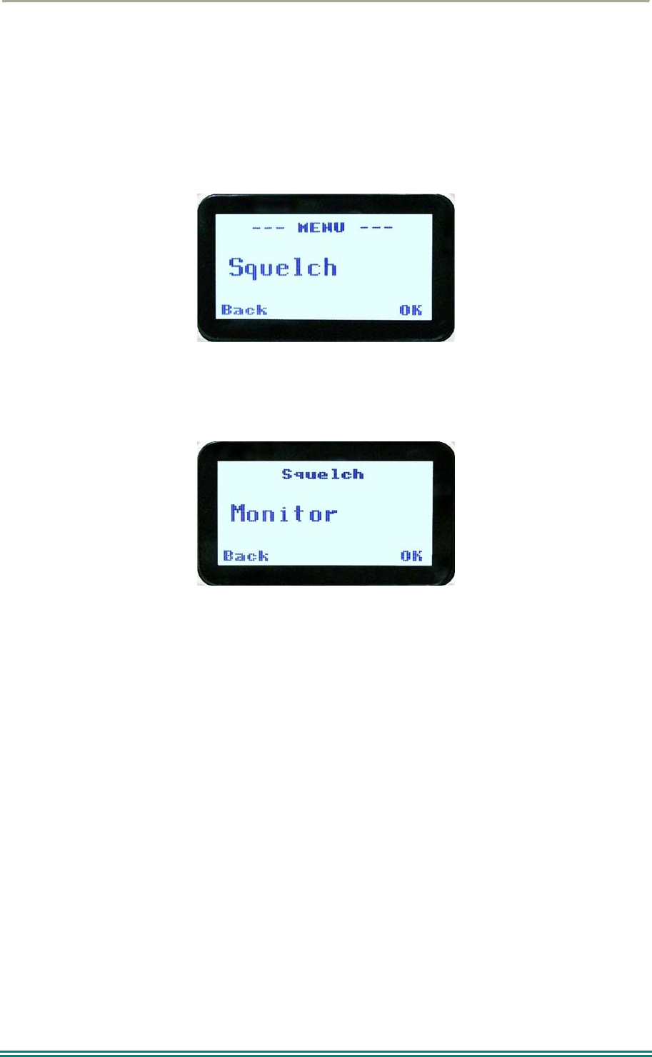
4.2.2 Squelch
This menu allows the channel’s default squelch mode to be modified.
If the selected channel is changed or the radio is switched off, the channel’s default squelch
setting will be restored.
Press the “OK” key for the “Squelch” Menu.
P25 Squelch Screen
For a P25 digital channel, pressing the ▼ and ▲ keys will allow selection of either Monitor,
Normal or Selective squelch mode.
For an analogue channel, pressing the ▼ and ▲ keys will allow selection of either Monitor
or Normal squelch mode.
4.2.2.1 Digital Operation
Channel Monitor Mode:
The radio will receive any decryptable or clear P25 digital voice signal. The Network Access
Code (NAC) is not checked. An “M” icon on the display indicates monitor mode.
Digital Channel Normal Mode:
When Normal squelch is selected, the radio will receive all decryptable or clear digital
transmissions with the correct NAC. Reception is not conditional upon the talkgroup or Unit
ID. An “N” icon on the display indicates normal squelch.
SRP9170/80 P25 Portable Radio – User Manual
© ComGroup Australia 2010 Page 19 TNM-U-E-0091 1.4a
Digital Channel Selective Mode:
If Selective squelch is chosen, the radio will only receive decryptable or clear digital
transmissions with the correct NAC and Talk Group ID (TGID) or correct NAC and Unit ID.
An “S” icon indicates Selective squelch.
4.2.2.2 Analogue Operation
Channel Monitor Mode:
The radio will receive any Analogue voice or P25 digital signals. Digital NAC or Analogue
CTCSS is not checked. An “M” icon indicates monitor.
Analogue Channel Normal Mode:
When Normal mute is selected, the radio will receive correctly addressed Analogue radio
transmissions and all decryptable or clear digital transmissions. An “N” icon indicates
Normal. Normal can only be selected if CTCSS/DCS is programmed for that channel.
Pressing the “OK” key returns to the main channel screen.
Pressing the “Back” or “M” key returns to the next highest menu level.
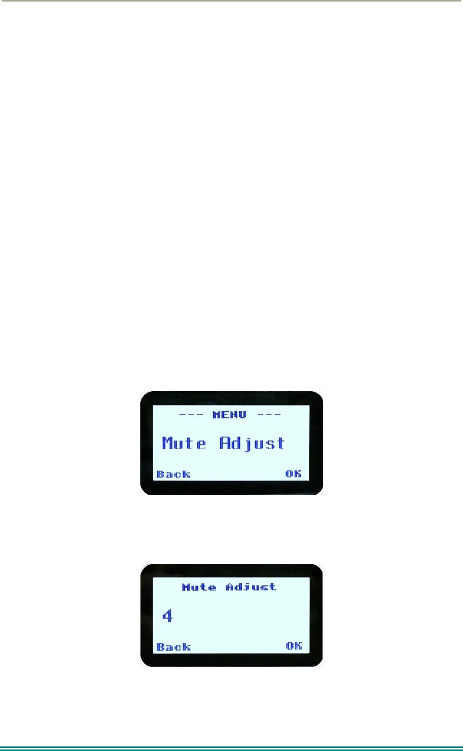
4.2.3 Mute Adjust / Monitor (Analogue Channels)
From the menu list, step through the menu options with the ▼ and ▲ keys until the “Mute
Adjust” menu is displayed.
Press the “OK” key for the Mute adjustment screen.
Analogue Mute Screen
The mute adjustment will be applied to all the radio’s analogue channels.
SRP9170/80 P25 Portable Radio – User Manual
© ComGroup Australia 2010 Page 20 TNM-U-E-0091 1.4a
Use the ▼ and ▲ keys to adjust the mute threshold. A numeric value of the present mute
level is shown.
The “OK” key returns to the default channel screen with the selected mute setting.
It is recommended that the default mute setting of 4 be used. The SRP9180 series radios
have a carrier noise mute and this means the mute will open at the point where an analogue
signal is sufficiently noise free to be intelligible with a setting of 4.
Where the default is not acceptable, it may be adjusted for analogue channels so that:
0 corresponds to “no muting”;
4 will hear all intelligible signals;
8 will hear slightly noisy signals and;
15 will only hear signals with no background noise.
Pressing the “OK” key will exit to the Channel Screen with the selected mute setting.
Direct access to the “Mute Adjust” screen from other screens can also be programmed to
one of the function keys with the Field Programmer.
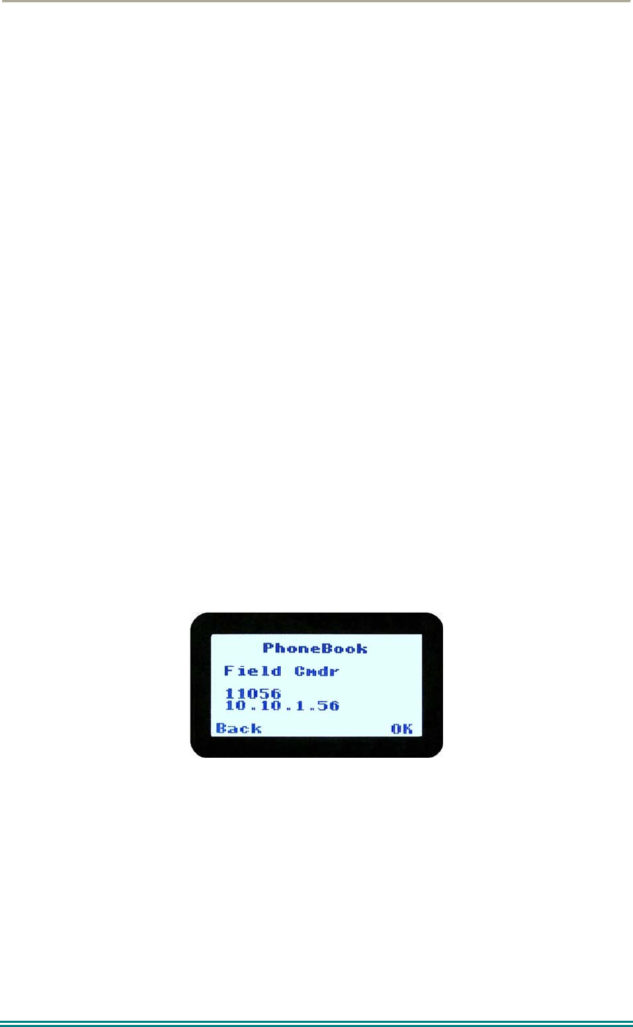
4.2.4 Phonebook
When “Phone Book” is selected from the menu screen, the Phone Book Screen is shown.
From this screen, it is possible to view the of all phone entries in the phone book.
Phone book entries may be Individual Addresses, Telephone numbers or Talk Groups.
The second line shows the name of the selected phone book entry.
The third line shows the unit identifier of the phone book entry. This is the P25 ID that the
radio will call.
The fourth line shows the IP address associated with the phone book entry. IP addresses
are used for data calls and text messages.
Phone book entries may be selected with the ▼ and ▲ keys.
A “Reset” function key press (if configured) takes the radio back to the default screen display.
When “Back” key “M” is pressed, the radio returns to the Menu screen.

SRP9170/80 P25 Portable Radio – User Manual
© ComGroup Australia 2010 Page 21 TNM-U-E-0091 1.4a
4.2.4.1 Making an Individual Call
In Phonebook mode, when the “PTT” key is pressed:
The radio is changed to individual call mode (individual call to the unit identifier of the
selected phone entry). The individual call icon is displayed.
If the radio is already in individual call mode addressed to a different unit, the
destination unit ID is replaced by that of the newly selected phone entry.
The radio will remain in individual call mode until the inactivity timeout has elapsed,
ie. No PTT or signal received for the Field Programmer set time period (typically 10
seconds).
The radio will return to the default channel screen.
4.2.4.2 Making an Individual Call with Call Alert
When the “OK” key is pressed with the Phone Book entry displayed:
A Call Alert is sent to the displayed ID.
The called radio will sound a Call Alert.
SRP9170/80 P25 Portable Radio – User Manual
© ComGroup Australia 2010 Page 22 TNM-U-E-0091 1.4a
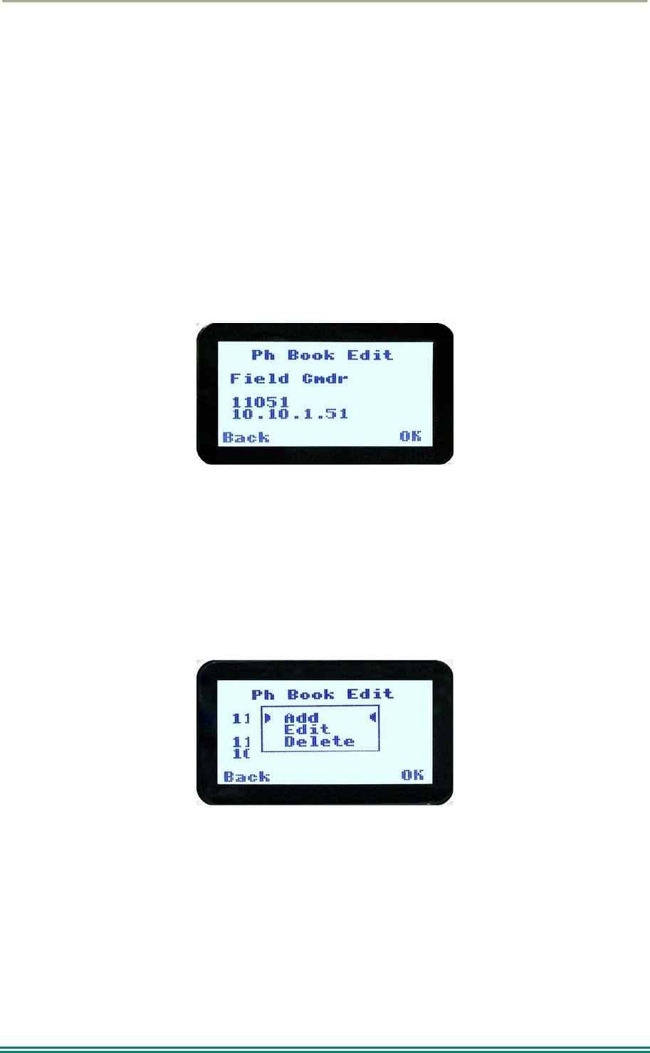
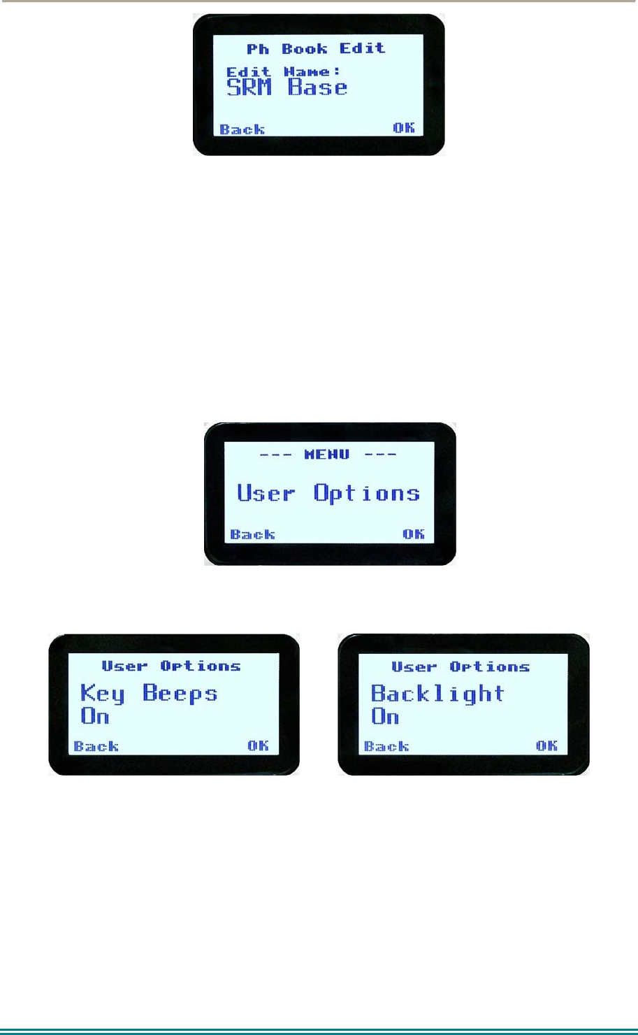
4.2.5 Phonebook Edit
The Phone Book can be modified so that new entries can be added and existing entries can
be modified or removed from the phone book.
Phone book entries may be Individual Addresses, Telephone numbers or Talk Groups.
Changes to the phone book are permanent.
4.2.5.1 Phonebook Edit Default Screen
When “Phone Book Edit” is selected from the menu screen, the radio displays the Phone
Book Edit Screen.
From this screen, an entry can be chosen using the ▼ and ▲ keys.
The displayed information is the same as the Phone Book Screen display.
A “Reset” function key press (if configured), takes the radio back to the default screen
display.
If the “Back” key “M” is pressed, the radio returns to the MENU screen.
If the “OK” key is pressed, the “Phone Book Edit” pop-up menu is displayed.
4.2.5.2 Phone Book Edit Pop-up menu
The pop-up items are:
Add: to add a new phone entry.
Edit: to edit (modify) the selected phone entry.
Delete: to delete the currently selected phone entry.
The selection is made with the ▼ and ▲ keys.
SRP9170/80 P25 Portable Radio – User Manual
© ComGroup Australia 2010 Page 23 TNM-U-E-0091 1.4a
The “M” or “Back” key takes the radio back to the Phone Book Edit Default Screen.
A “Reset” function key press (if configured) takes the radio back to the default screen
display.
If “Delete” is selected, pressing “OK” removes the selected phone entry from the phone book
and takes the radio back to the default screen display.
If “Add” is selected, pressing “OK” takes the radio to the Add New Entry sub-menu.
If “Edit” is selected, pressing “OK” takes the radio to the Edit Phone Entry sub-menu.
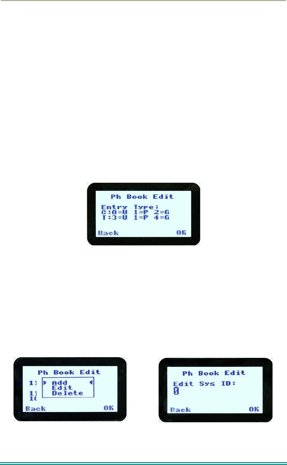
4.2.5.3 Phone Book Edit – Add New Phone Entry
The first edit screen is the entry type screen. There are 6 possible types of Phone Book
entries. These are:
Conv.Unit ID (Option 0) Conv.PSTN (Option 1) Conv.Group (Option 2)
Trunk Unit ID (Option 3) Trunk PSTN (Option 1) Trunk Group (Option 4)
Make the selection 0 – 5 and select OK.
From here, enter the System ID value as described in the Phonebook Edit section.
4.2.5.4 Phonebook Edit
This selection is used to edit an existing phone book entry. The operation is similar to adding
a phonebook entry in previous section. In this example, editing a P25 Trunked ID is shown.
It is also possible to edit a P25 Conventional ID and a P25 Group Entry. Note that some
steps will be missing for a Conventional channel.
The first step is to edit the System ID, if required.
Upon entering this screen, the current trunked System ID of the selected phone entry is
displayed.
SRP9170/80 P25 Portable Radio – User Manual
© ComGroup Australia 2010 Page 24 TNM-U-E-0091 1.4a
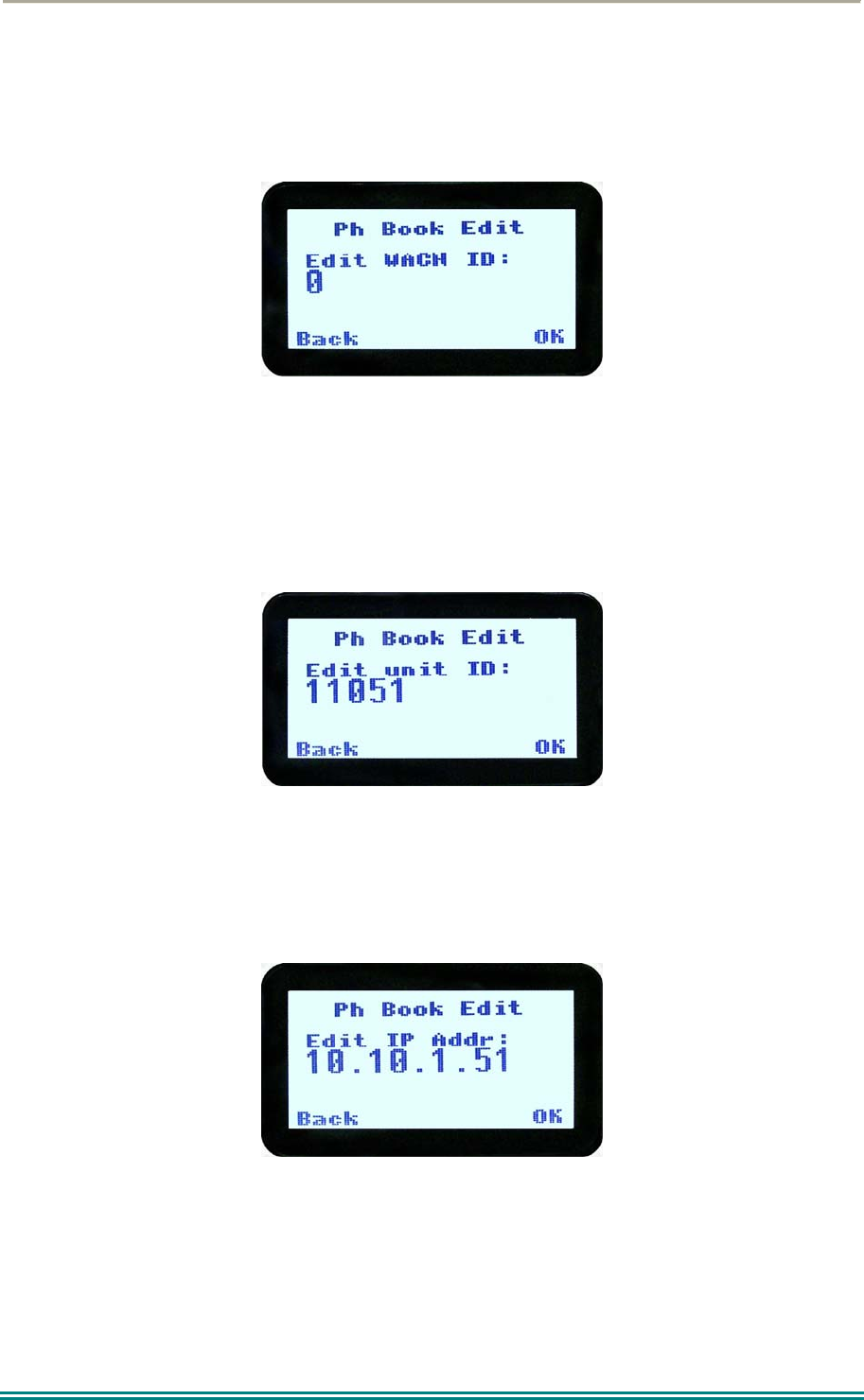
The System ID entry can then be changed using the numeric digits and ▼ key as a
destructive backspace.
Once the new System ID is entered, press “OK” key to move on to the next sub-menu screen
to edit the Wide Area Coverage Network (WACN) ID, if required.
Upon entering this screen, the current WACN ID of the selected phone entry is displayed.
The WACN ID entry can then be changed using the numeric digits and ▼ key as a
destructive backspace and # for the “.”.
If there is no change for the WACN ID, press “OK” key to move on to the next sub-menu
screen to edit the Unit ID, if required.
Upon entering this screen, the current Unit ID of the selected phone entry is displayed.
The name entry can then be changed using the numeric digits and ▼ and ▲ key to move the
cursor with Reset function key to delete.
If there is no change for the Unit ID, press “OK” key to edit the IP address, if required.
Upon entering this screen, the current IP address of the selected phone entry is displayed.
The IP address can then be changed using the numeric digits and ▼ and ▲ key to move the
cursor with Reset function key to delete. The “#” key is used to enter a “.”.
If there is no change for the IP address, press “OK” key and move on to the next sub-menu
screen to edit the name.
SRP9170/80 P25 Portable Radio – User Manual
© ComGroup Australia 2010 Page 25 TNM-U-E-0091 1.4a
Upon entering this screen, the current name of the selected phone entry is displayed.
The name entry can then be changed using the numeric digits and ▼ and ▲ key to move the
cursor with Reset function key to delete.
If there is no change for the name, press “OK” key to complete the editing on the phone
entry. The phone entry will be modified in the radio, and the radio will return to the default
screen.
4.2.6 User Options
The “User Options” menu provides access to a list of Functions that may be toggled on or
off. Up to 10 functions may be defined in this menu by the FPP programmer.
Press the “OK” key for the “User Options” screen.
When the Function is selected, the function can be toggled ON or OFF with the “OK” key.
The ▼ and ▲ keys are used to select the other functions.
Pressing the “Back“ / “M” key saves all the function settings and returns to the next highest
menu level.
Toggle functions include Key Beeps, Backlight, Talk-Around, Analogue Scrambler and Low
Power Override.
These functions can also be assigned directly to the radio’s function keys, if required.
SRP9170/80 P25 Portable Radio – User Manual
© ComGroup Australia 2010 Page 26 TNM-U-E-0091 1.4a
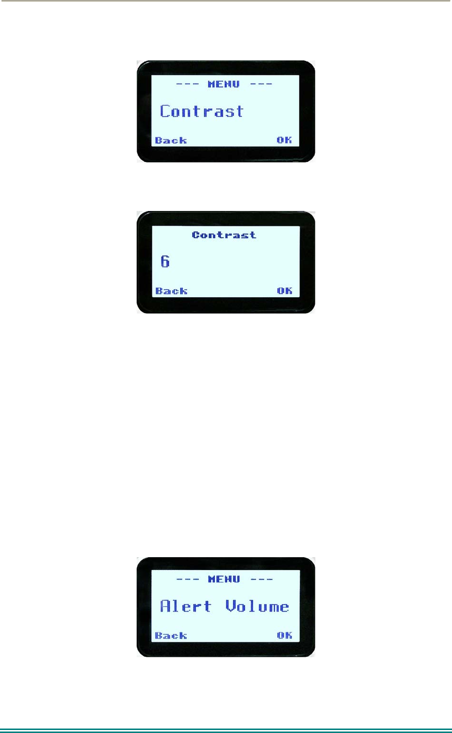
4.2.7 Contrast
This menu allows the screen’s contrast setting to be altered.
Press the “OK” key for the “Contrast” adjustment screen.
When the “Contrast” menu is selected, the contrast can be adjusted with the ▼ and ▲ keys.
The numeric value of the Contrast is displayed.
Pressing the “OK” key returns to the main channel screen.
Pressing the Back or “M” key returns to the next highest menu level.
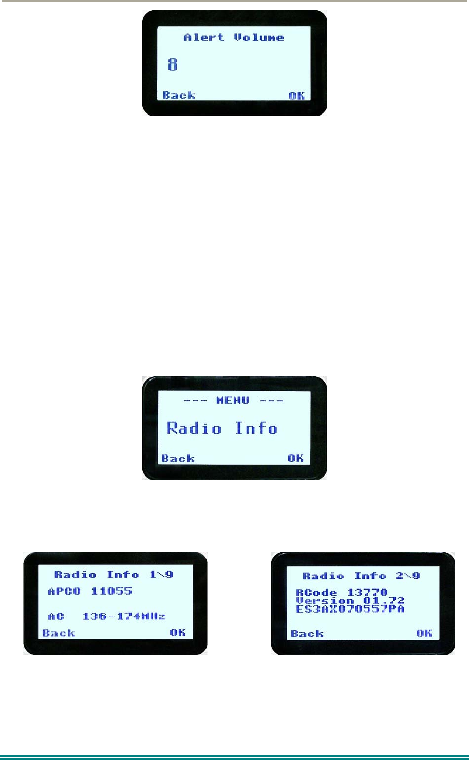
4.2.8 Alert Volume
This Screen allows you to set the level of the relative Alert Volume level in relation to the
current Volume setting. The level can be set in 62 steps over the range -31 to +31, with 0
being about the same as the voice level. For example, if the alert volume is set to –6, it will
be softer than received voice on the radio.
From the Settings Sub Menu, step through the menu options with the ▼ and ▲ keys until the
Alert menu is displayed.
Press the “OK” key for the “Alert Volume” adjustment screen.
SRP9170/80 P25 Portable Radio – User Manual
© ComGroup Australia 2010 Page 27 TNM-U-E-0091 1.4a
Use the ▼ and ▲ keys to change the relative alert volume level. The beep will sound at the
indicated level each time the setting is changed.
Press OK to accept the setting and return to the Channel Screen.
Pressing the M key will exit back to the setup menu.
Note: A minimum Alert Level may be set by the FPP to ensure the Alerts can always be
heard from the speaker.
4.2.9 Radio Info
These screens display information that identifies the Field Programmer File description,
Radio ID, Serial Number, Software Version and IP Address.
From the Settings Sub Menu, step through the menu options with the ▼ and ▲ keys until the
Radio Info menu is displayed.
Press the “OK” key for the “Radio Info” Screen.
The ▼ and ▲ keys select the following information pages:
P25 Conv. ID and Radio Band
Radio Software Version and Serial Number
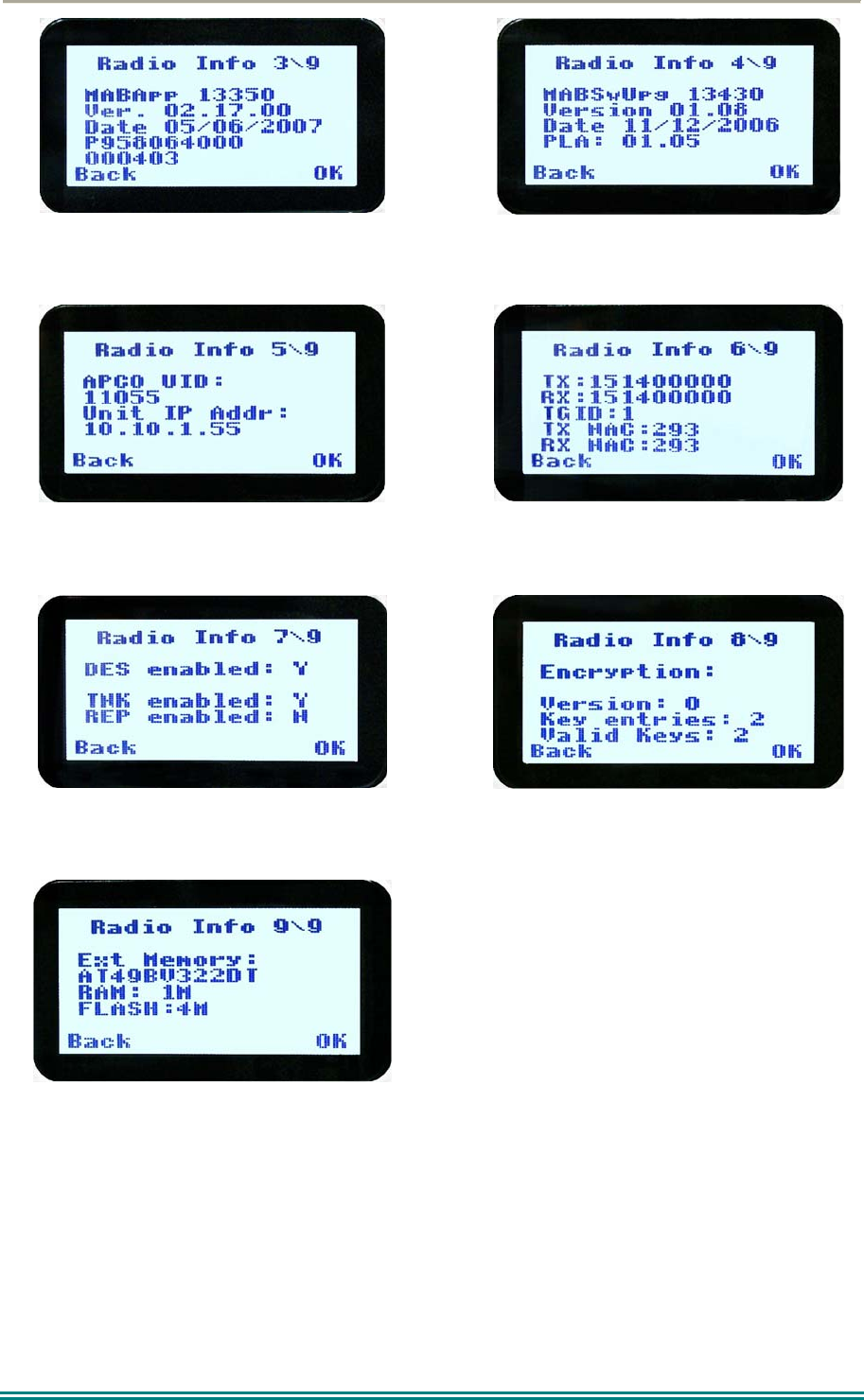
SRP9170/80 P25 Portable Radio – User Manual
© ComGroup Australia 2010 Page 28 TNM-U-E-0091 1.4a
Application Software Version and Date
Application Upgrade Version, Date and PLA
code
P25 Radio Unit Trunked ID and IP Address
P25 Trunked SysID, WACN, GID and UID
Feature Authorisation Enables
Encryption Status
External Application Memory Status
The “Radio Info“ screens are read-only screens. Press “OK” to return to the Channel
Screen.
SRP9170/80 P25 Portable Radio – User Manual
© ComGroup Australia 2010 Page 29 TNM-U-E-0091 1.4a
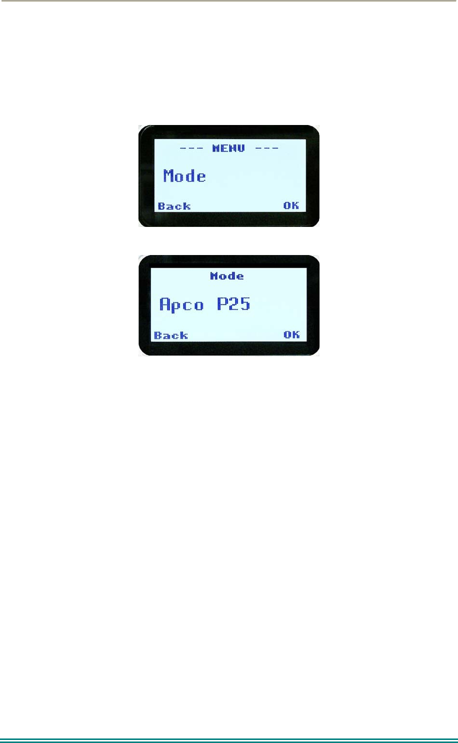
4.2.10 Mode
The mode menu is used for changing from one radio to another, such as PMR/LMR mode to
P25 or MPT1327 trunking.
From the Channel Screen, select menu mode with the “M” or “Menu” key and step through
the menus with the ▼ and ▲ keys until the “Mode” menu is reached.
Press “OK” to select the Mode menu.
From the “Mode” menu, use the ▼ and ▲ keys to select the required operating mode, such
as APCO P25, PMR or MPT Trunking. While the required mode is displayed, press OK to
select that operating mode. The radio will then display the default screen for that mode.
Keypad shortcuts can be used to change modes from the keypad.
PMR (*60#)
P25 (*80#)
MPT Network 1 (*71#)
MPT Network 2 (*72#)
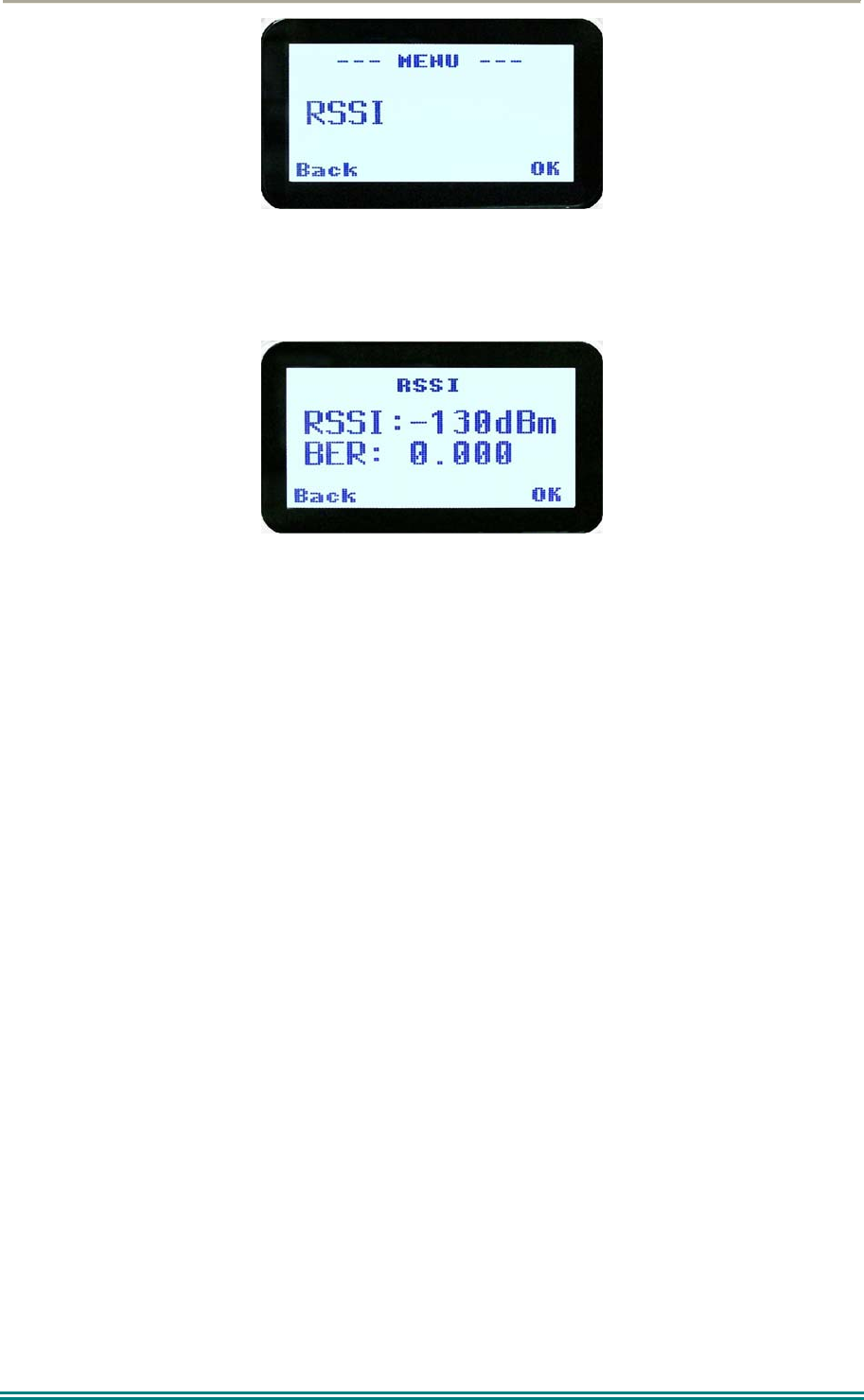
4.2.11 RSSI
This screen displays the received signal strength in dBm. The reading is typically accurate
within +/- 2 dBm between –120dBm and -80dBm, when the radio has been correctly
calibrated. For example, -90dBm is a strong signal and –120dBm is no signal.
The screen also shows the Bit Error Rate (BER) on digital channels. RSSI and BER are
typically used to indicate signal quality.
From the Settings Sub Menu, step through the menu options with the ▼ and ▲ keys until the
“RSSI” menu is displayed.
SRP9170/80 P25 Portable Radio – User Manual
© ComGroup Australia 2010 Page 30 TNM-U-E-0091 1.4a
Press the “OK” key for the “RSSI“ screen
If a Digital channel is selected BER will be displayed.
The RSSI/BER will be displayed until either the “M” key is pressed to return to the next
highest menu level or the “OK” key is pressed which will return to the main channel menu.
A lower RSSI value indicates a stronger signal, i.e. –80dBm is a stronger signal than –
100dBm.
SRP9170/80 P25 Portable Radio – User Manual
© ComGroup Australia 2010 Page 31 TNM-U-E-0091 1.4a
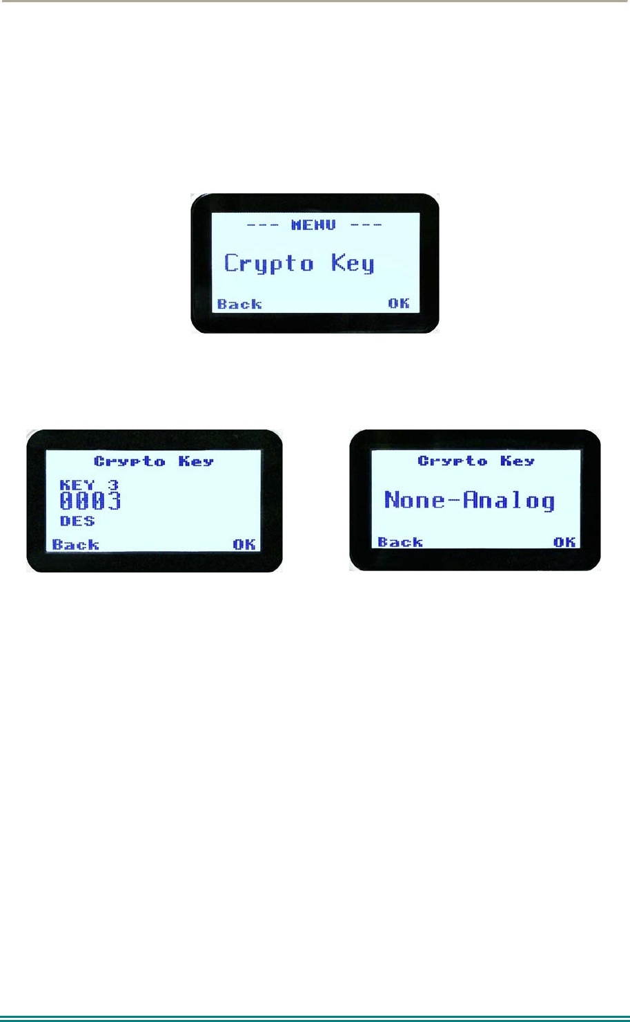
4.2.12 Crypto
This menu allows the digital channel’s default transmit encryption key to be modified. On an
encrypted radio channel, the radio will attempt to use any of the stored encryption keys to
decrypt received signals.
The current selected digital channel has encryption enabled if the padlock symbol is
displayed.
Press the “OK” key for the “Crypto Key” menu.
Digital Analogue
When the Crypto menu is selected, the digital channel’s Encryption Key ID can be changed
with the ▼ and ▲ keys.
The key name and the key identifier (1-32) for the selected channel is displayed.
If the selected channel is changed or the radio is switched off, the channel’s default
encryption key will be restored.
Pressing the “OK” key returns to the main channel screen.
Pressing the “Back” or “M” key returns to the next highest menu level.
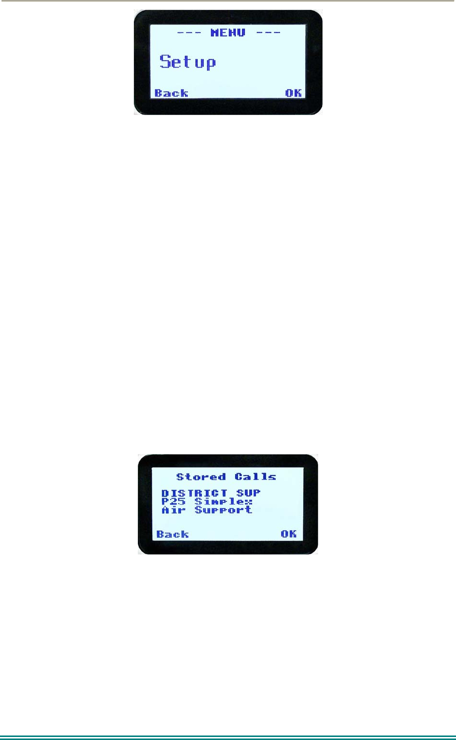
4.2.13 Setup
The screens in the Setup sub-menus allow the radio operator to edit/modify the operation of
some of the general functions of the radio.
Once the “M” key is pressed from the “Channel” screen, the ▼ and ▲ keys cycle through
the available “Main” menus. Once the “Setup” menu appears, press the “OK” key to select
it.
SRP9170/80 P25 Portable Radio – User Manual
© ComGroup Australia 2010 Page 32 TNM-U-E-0091 1.4a
The ▼ and ▲ keys are then used to scroll through the setup menus.
The Setup menu structure may include, for example:
Alert Volume,
Contrast,
RSSI (Received Signal Strength Indication),
Info (Radio software and hardware information),
Crypto (Select Transmit Encryption Key),
Squelch,
Mute Adjust, or
User Options.
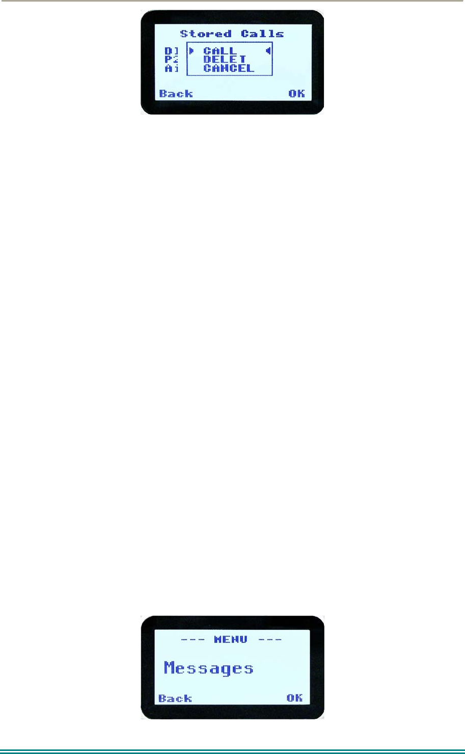
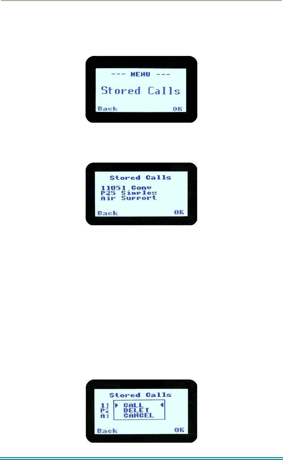
4.2.14 Stored Calls
This screen displays the received individual call records one by one, starting with the most
recently received call record.
Either the name of the caller from the phone book or the user ID is displayed if the ID is not
known to the phone book. If stored calls are empty, NO RECORD is displayed.
The ▼ and ▲ keys can be used to step through the stored calls. An error beep will sound if
there are no more call records.
A “Reset” function key press (if configured), takes the radio back to the default screen
display.
The “M” or “Back” key returns to Menu screen. When “OK” key is pressed, a pop up menu
is displayed so that the message can be deleted or party called back.
SRP9170/80 P25 Portable Radio – User Manual
© ComGroup Australia 2010 Page 33 TNM-U-E-0091 1.4a
The selections are:
DELETE – to delete the call record.
CALL – to call back the caller (set individual call to the caller).
CANCEL – to cancel the action selection.
The selection is made with the▼ and ▲ keys.
The “M” or “Back” key returns to Stored Calls screen”.
A “Reset” function key press (if configured) takes the radio back to the default screen display.
If “CALL” is selected, pressing “OK” sets the radio to individual calling mode with the ID of
the stored call. A subsequent PTT within the configured time interval will send an individual
call to the ID of the stored call.
If “DELETE” is selected, pressing “OK” removes the selected call record (being viewed) from
the list. The radio returns to the Stored Calls Screen with the next record being displayed.
If “CANCEL” is selected, the Stored Calls screen is displayed.
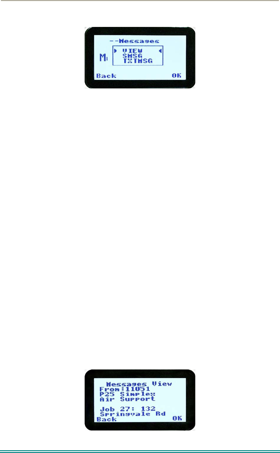
4.2.15 Messages
A P25 radio can receive and transmit predefined short messages and text messages with
another radio unit on a digital channel (P25 conventional only).
Messages received are stored in radio memory. They can be viewed and deleted as
required.
If there are unread messages stored in the radio, the envelope icon on the default screen will
flash.
If there are messages in the radio that have all been read, a steady envelope icon is shown
on the default screen.
If there are no messages in the radio, the envelope icon will not appear on the default
screen.
To view/delete/send messages, go to the Menu selection and choose the “Messages” menu.
SRP9170/80 P25 Portable Radio – User Manual
© ComGroup Australia 2010 Page 34 TNM-U-E-0091 1.4a
When “Messages” is selected from the menu screen with “OK”, a pop-up screen will appear.
4.2.15.1 Messages Selection Pop-Up Menu
The pop-up selections are:
VIEW: view received messages.
SMSG: Short Message. The radio can be programmed with a list of predefined
messages. Choosing SMSG shows a list of predefined messages, which can be
sent as a short message to another radio unit. Only applicable when a digital
channel is selected.
TXTMSG: Text message. Enters the text message edit and send sub-menus. Only
applicable when a digital channel is selected.
Options are selected with the ▼ and ▲ keys.
Pressing “M” or “Back” keys takes the radio back to the Menu screen.
A “Reset” function key press (if configured), takes the radio back to the default screen
display.
If “VIEW” is selected, pressing “OK” shows the Message View screen.
If “SMSG” is selected, pressing “OK” shows the Short Message screen only for a digital
channel, otherwise an error beep will sound.
If “TXTMSG” is selected, pressing “OK” shows the Edit Text Message screen only for a
digital channel, otherwise an error beep will sound.
4.2.15.2 View Received Messages Screen
Received messages (both short messages and text messages) can be viewed from this
screen.
This screen displays the received messages one by one, starting with the most recent
received message.
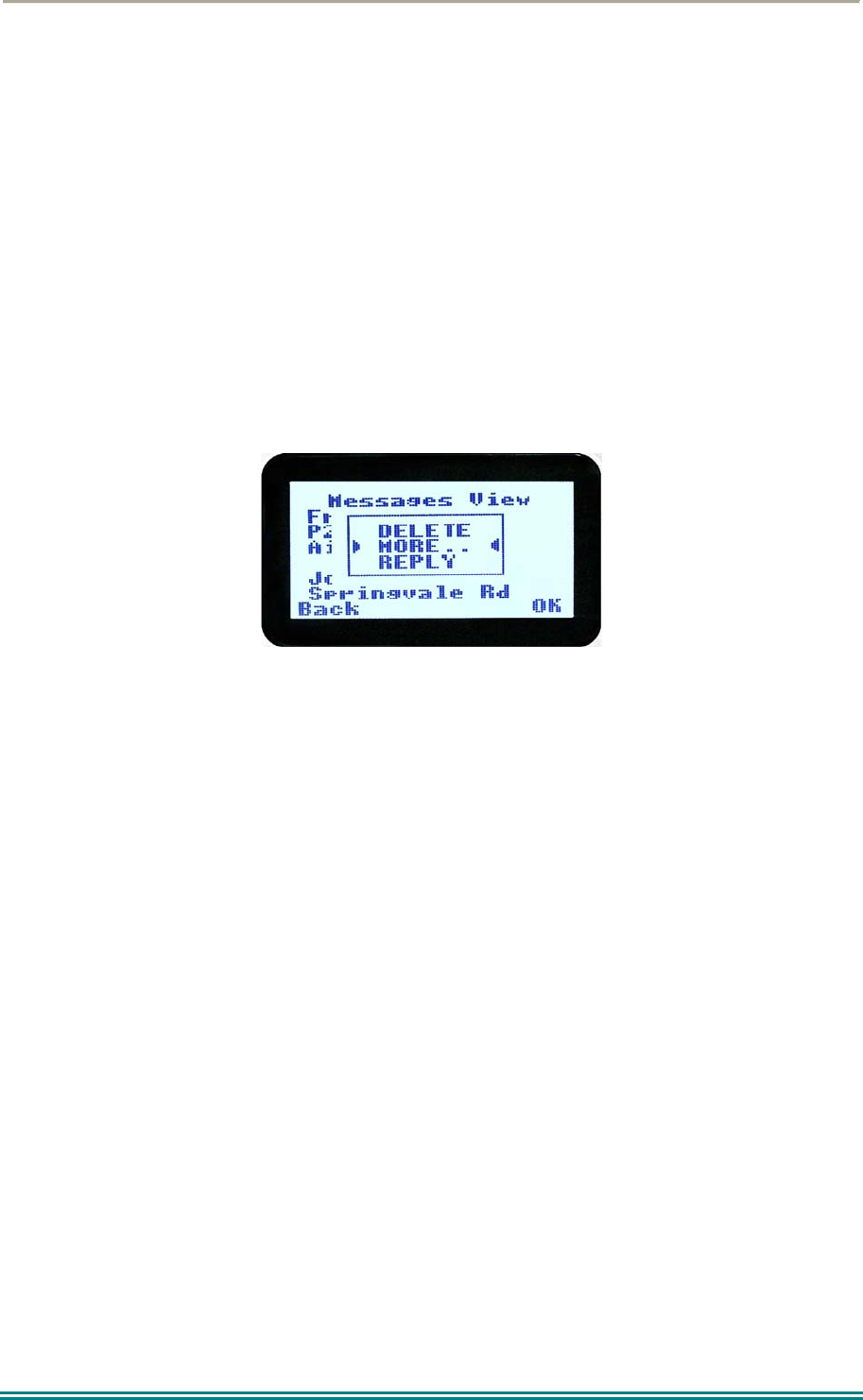
SRP9170/80 P25 Portable Radio – User Manual
© ComGroup Australia 2010 Page 35 TNM-U-E-0091 1.4a
The information displayed for each message includes the sender ID and the first 2 lines of
the received message in text string.
If no messages are stored, “NO RECORD” is displayed.
To step through other stored messages, use the▼ and ▲ keys. If there is no further
message stored, an error beep will sound.
A “Reset” function key press (if configured), takes the radio back to the default screen
display.
If the “Back” or “M” key is pressed, the radio will return to the Messages Selection pop-up
Menu.
Pressing the “OK” key displays the Message View pop-up menu with further options.
4.2.15.3 Message View Pop-Up Menu
The Message View pop-up allows the following options:
DELETE: deletes the current received message.
MORE: to view the full (entire) message.
REPLY: to select the method of replying to the selected message.
Selection is performed using the ▼ and ▲ keys.
Pressing the “M” or “Back” key takes the radio back to the “Messages View” Screen.
A “Reset” function key press (if configured), takes the radio back to the default screen
display.
If “DELETE” is selected, pressing “OK” will remove the current selected message from the
radio. The radio will return to the “Messages View” screen with the next message being
selected and displayed.
If “MORE” is selected, pressing “OK” will display the full message.
If “REPLY” is selected, pressing “OK” will display the “Message Reply” pop-up screen.
SRP9170/80 P25 Portable Radio – User Manual
© ComGroup Australia 2010 Page 36 TNM-U-E-0091 1.4a
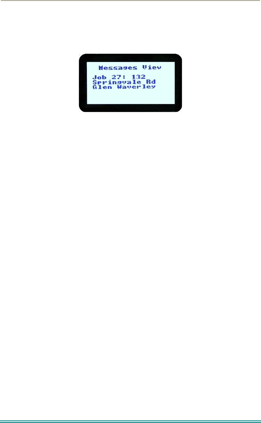
4.2.15.4 More Message View Screen
This screen displays the selected message in full scale – 6 lines of message text per page of
the selected message.
If a message exceeds a screen, the ▼ and ▲ keys can select the other pages.
Pressing “M” or “OK” returns to the “Messages View” pop-up screen.
The “Reset” function key press (if configured), takes the radio back to the default screen
display.
SRP9170/80 P25 Portable Radio – User Manual
© ComGroup Australia 2010 Page 37 TNM-U-E-0091 1.4a
4.2.15.5 Reply Message Selection Pop-Up Menu
Selecting Reply brings up another pop-up menu.
The selections are:
CALL: calls the selected sender.
SMSG: sends a short message to the sender.
TXTMSG: to edit and send a text message to the sender.
Selection is made using the ▼ and ▲ keys.
The “M” or “Back” key press returns to the “Messages View” pop-up screen.
A “Reset” function key press (if configured), takes the radio back to the default screen
display.
If “Call” and “OK” is selected, the radio returns to the default screen and is set to individual
calling mode for a time out period determined by radio configuration.
When the radio’s PTT is activated, an individual voice call is sent to the message sender.
If “SMSG” is selected, pressing “OK” displays the Message Reply - Short Messages screen.
If “TXTMSG” is selected, pressing “OK” displays the Message Reply –Text Edit screen.
4.2.15.6 Short Message Reply
This menu is used to reply with a pre-defined short message.
This screen shows the destination unit identifier and the selected short message.
The short message can be selected from the short message list by using the ▼ and ▲ keys.
SRP9170/80 P25 Portable Radio – User Manual
© ComGroup Australia 2010 Page 38 TNM-U-E-0091 1.4a
A “Reset” function key press (if configured), takes the radio back to the default screen
display.
A “Back” or “M” keypress returns to the Message Reply Pop-up screen.
When “OK” key is pressed, the selected short message is sent in reply to the received
message, and the radio returns to the default screen.
4.2.15.7 Text Message Reply Screen
This menu is used to reply with a free form text message.
The maximum length of text message is 210 characters. The number of characters entered
is displayed in the top right hand side.
The characters are entered via the keypad by pressing the relevant key one or more times to
choose each character.
The ▼ key is used to move the curser to the left.
The ▲ key is used to move the curser to the right.
A “Reset” key press and hold for less than one second deletes the character to the left of the
cursor, and moves the curser position to the left by one.
Holding the “Reset” key down for more than one second deletes all characters from the
curser position to the right. A new character entered is put on the current cursor location.
The ‘#’ key is used to toggle upper and lower case.
The “0” key is the space key.
When “Back” key “M” is pressed, the radio returns to the Message Reply pop-up screen.
Pressing “OK” sends the edited text message in reply to the sender of the message. The
radio returns to the default screen.
SRP9170/80 P25 Portable Radio – User Manual
© ComGroup Australia 2010 Page 39 TNM-U-E-0091 1.4a
4.2.15.8 Send Message (Short or Text)
This menu is used to send either a short message or a text message to another party.
Select Messages from the main menu and then choose either “SMSG” (Short Message) or
“TXTMSG” (Text Message).
This screen allows the user to view and select a short message. It displays the selected
short message text.
The short message can be selected by using the ▼ and ▲ keys.
A “Reset” function key press (if configured) takes the radio back to the default screen
display.
A “Back” or “M” keypress returns to the Message Pop-up screen.
When the “OK” key is pressed, the Destination Pop-up screen is shown.
SRP9170/80 P25 Portable Radio – User Manual
© ComGroup Australia 2010 Page 40 TNM-U-E-0091 1.4a
4.2.15.9 Text Message Screen
This screen allows editing and sending a free form text message. A text message can have
a maximum length of 210 characters. The number of characters entered is displayed in the
top right hand side.
The characters are entered via the keypad by pressing the relevant key one or more times to
choose each character.
The ▼ key is used to move the curser to the left.
The ▲ key is used to move the curser to the right.
A “Reset” key press and hold for less than one second deletes the character to the left of the
cursor, and moves the curser position to the left by one.
Holding the “Reset” key down for more than one second deletes all characters from the
curser position to the right. A new character entered is put on the current cursor location.
The ‘#’ key is used to toggle upper and lower case.
When “Back” key “M” is pressed, the radio returns to the Message Reply pop-up screen.
When “OK” key is pressed, the Destination Selection Pop-up Menu screen appears.
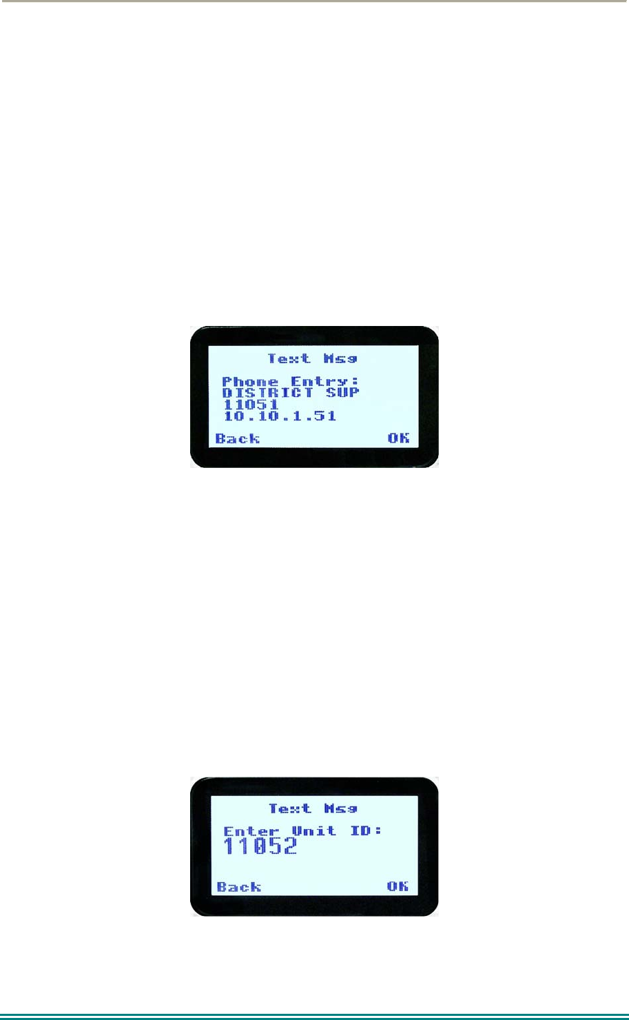
4.2.15.10 Destination Select Pop-Up Menu
This menu allows selection of the message destination.
The selections are:
PHBK: to select the destination from the phone book.
ENT.ID: enter the destination unit ID.
CANCEL: to cancel the destination selection.
Use the ▼ and ▲ keys to make the selection.
SRP9170/80 P25 Portable Radio – User Manual
© ComGroup Australia 2010 Page 41 TNM-U-E-0091 1.4a
The “M” or “Back” key returns to previous screen, i.e., Short Message Screen, or Edit Text
Message Screen.
A “Reset” function key press (if configured) takes the radio back to the default screen
display.
If “CANCEL” is selected, pressing “OK” returns to the previous screen, i.e., Short Message
Screen, or Edit Text Message Screen.
If “PH.BK” is selected, pressing “OK” key displays the “Phone Entry Screen”.
If “ENT.ID” is selected, pressing “OK” key displays the “Enter Unit Id Screen”.
4.2.15.11 Phone Book Selection Screen
This screen allows selection of the destination ID from the Phone Book.
The ▼ and ▲ keys are used to select the phone book entry.
A “Reset” function key press (if configured) takes the radio back to the default screen
display.
The “M” or “Back” key returns to the Destination Selection Pop-up screen.
Pressing “OK” key sends the message to the chosen destination ID and the radio returns to
the default screen.
4.2.15.12 Enter Unit ID Screen
This screen allows manual entry of the destination unit ID decimal digits. The valid range of
a unit ID is 0 – 16,777,215.
The entered digits can be deleted by using the ▼ key.
The “M” or “Back” key returns to Destination Selection pop-up Menu screen.
SRP9170/80 P25 Portable Radio – User Manual
© ComGroup Australia 2010 Page 42 TNM-U-E-0091 1.4a
A “Reset” function key press (if configured), takes the radio back to the default screen
display.
Pressing “OK” sends the message to the entered unit ID (providing it is valid). The screen
will return to the default screen.
If the entered unit ID is not valid, or the IP address is not defined, an error beep will sound.
Sending a short message or text message can fail if the destination radio is not available.
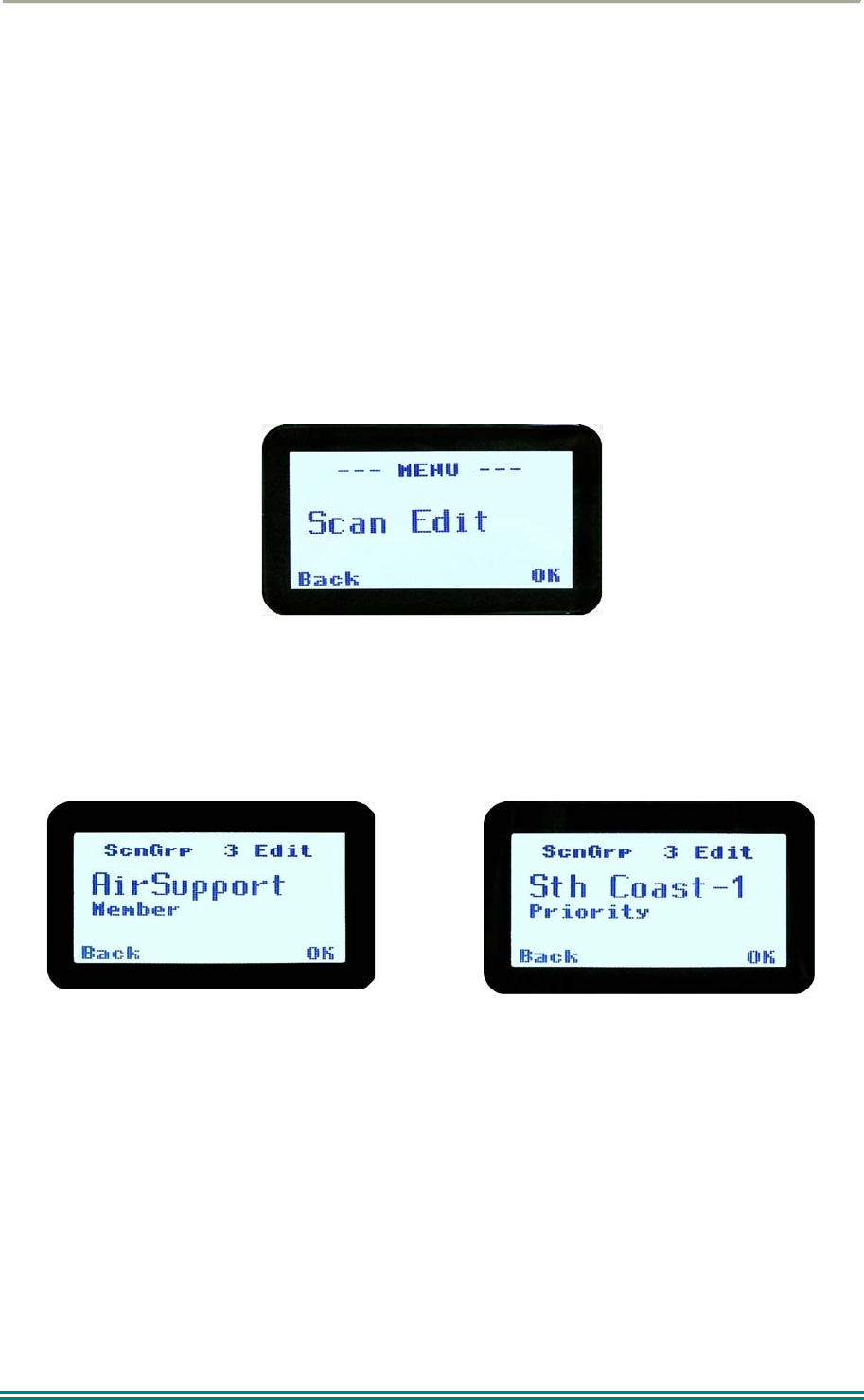
4.2.16 Scan Edit Menu
This menu allows channels in Scan Groups to be added or deleted by the user.
Add and Delete changes to a Scan Group are stored permanently in the radio.
4.2.16.1 Scan Group Edit Screen
When selected, the “Scan Group Edit” screen is displayed, which shows the channels within
the Scan Group.
The second line from the top shows the name of the selected channel in the scan group.
The next line shows the channel type, i.e., “Member” if it is a normal member of the scan
group; “Priority” if it is the priority channel; or “Skipped”, if the channel is currently skipped
from the scan group.
The ▼ and ▲ keys select the channel from the scan group list.
When “Reset” function key is pressed (if configured), the radio returns to the default screen
display.
When the “Back” key or “Menu” is pressed, the radio returns to the “Scan Group Edit”
screen.
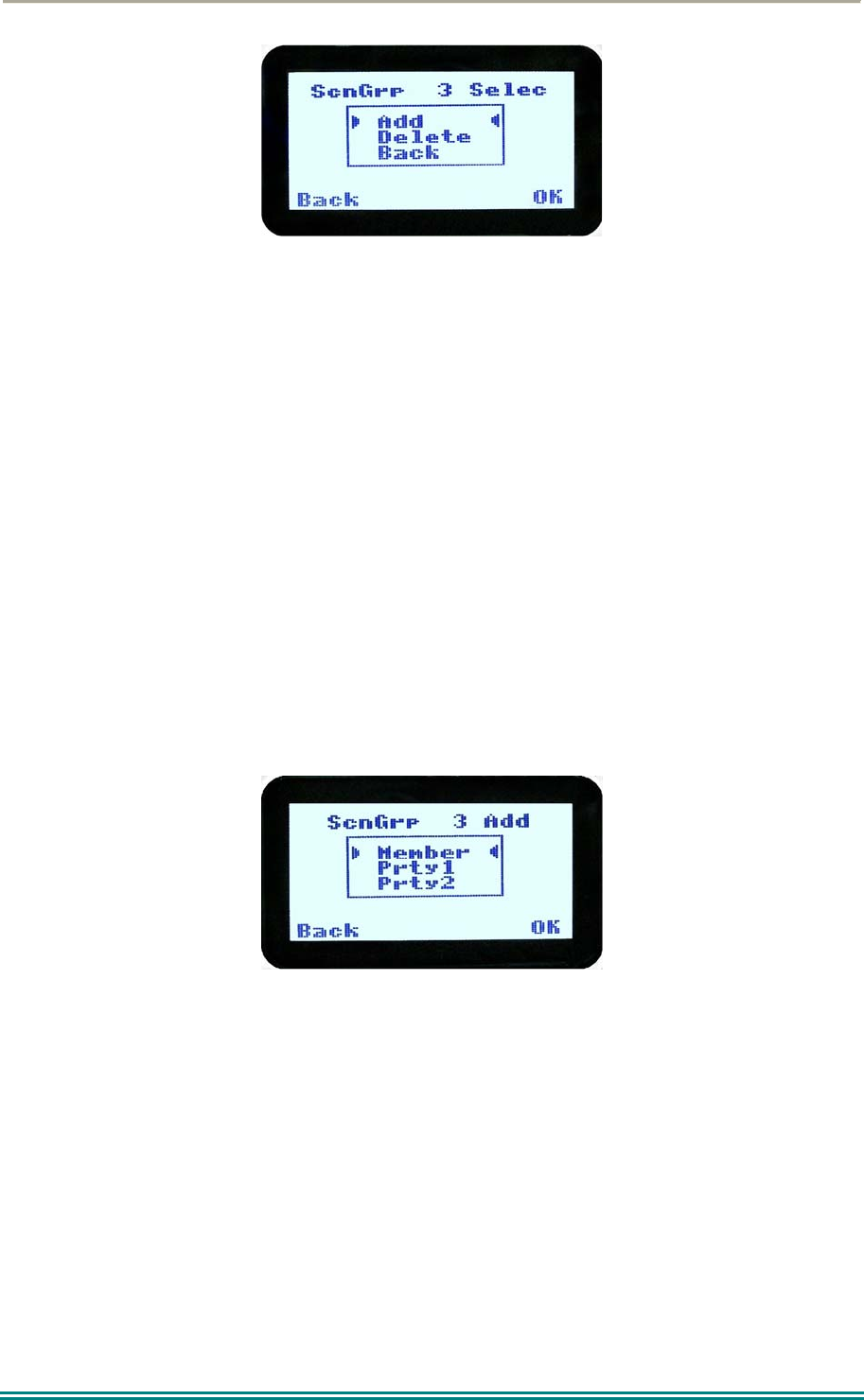
When “OK” key is pressed, a pop-up action selection menu is displayed.
SRP9170/80 P25 Portable Radio – User Manual
© ComGroup Australia 2010 Page 43 TNM-U-E-0091 1.4a
The pop-up selections are:
Add: adds a channel to the scan group.
Delete: deletes the currently selected channel from the scan group.
Back: returns to previous menu screen.
The ▼ and ▲ keys make the selection.
The “Menu” or “Back” key takes the radio back to the “Scan Edit” main screen.
A “Reset” function key press (if configured) takes the radio back to the default screen
display.
If “Delete” is selected, pressing “OK” key removes the selected channel from the scan group
and takes the radio back to the default screen display. If scanning is enabled on the current
channel, scanning will start. The deletion is permanent.
If “Add” is selected, pressing “OK” key takes the radio to the Scan Group Add Type screen.
The priority level of the channel to add to the scan group is selected from this screen. The
choices are:
Member: A member channel is a normal channel with lowest priority in the scan
group.
Prty1: A Priority 1 channel will have the highest priority in the scan group.
Prty2: A Priority 2 channel will have the second highest priority in the scan group.
The priority of the channel is selected using the ▼ and ▲ keys and pressing OK. The Scan
Group Add screen will appear next.
SRP9170/80 P25 Portable Radio – User Manual
© ComGroup Australia 2010 Page 44 TNM-U-E-0091 1.4a
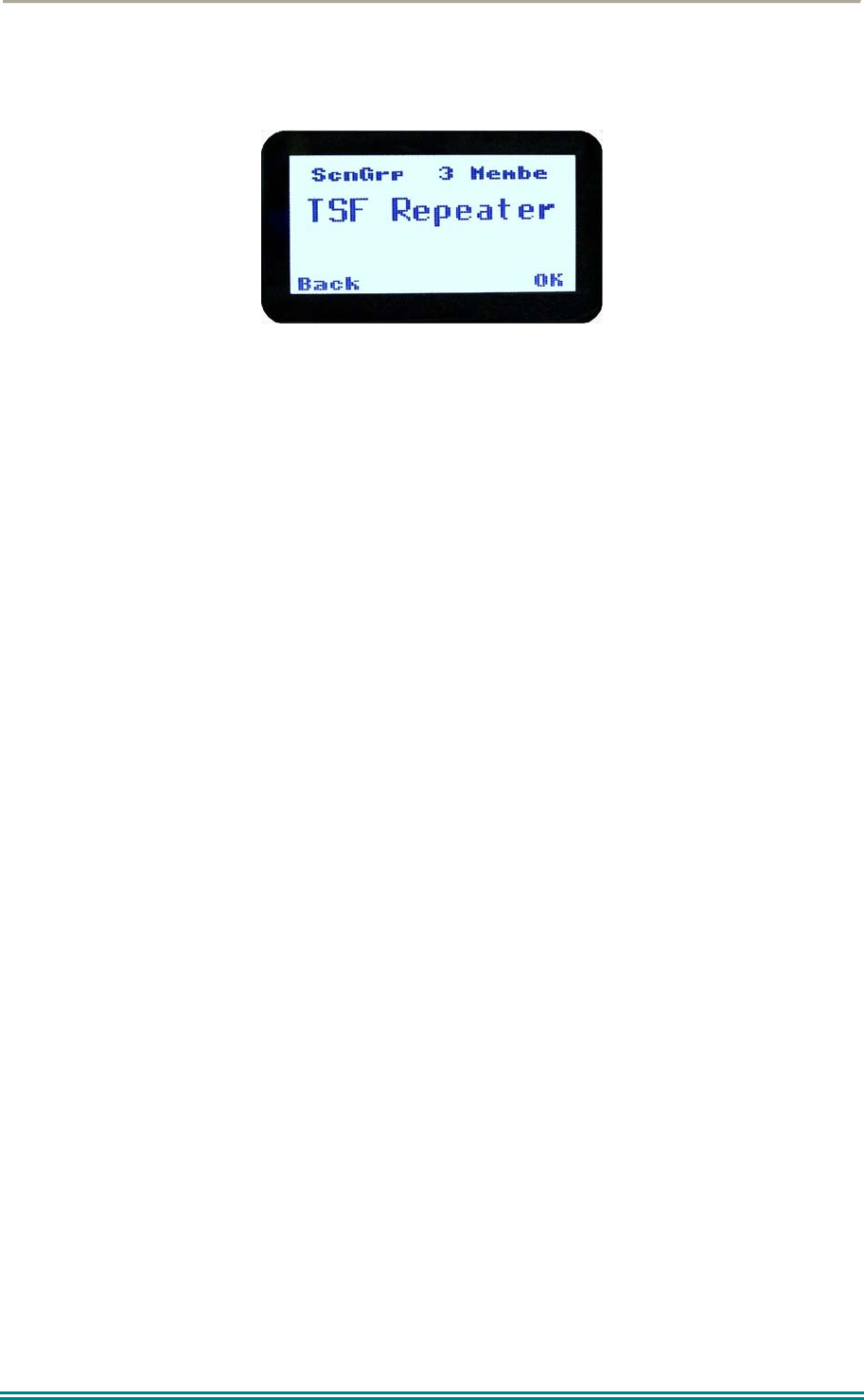
4.2.16.2 Scan Group Add Screen
The “Scan Group Add” screen shows channels that are not members of the Scan Group.
The second line from the top shows the name of a channel that is not a member of the Scan
Group.
Other channels that are not members of the scan group can be selected using the ▼ and ▲
keys.
A “Reset” function key press (if configured) takes the radio back to the default screen
display.
When the “Back” key or “Menu” is pressed, the radio returns to the main Scan Edit screen.
When “OK” key is pressed,
If the scan group has less than 15 member channels, the selected non-member
channel is added to the scan group. If scan is enabled on the current channel, the
radio will resume scanning. The radio returns to the default screen. The added
channel is permanent.
Otherwise, an error beep will sound, and the radio will return to the default screen.
4.2.17 No Menu
The “No Menu” option exists in the FPP for when a menu entry is not required. If all entries
are “No Menu”, there will be no menu system available. This may be desirable for simple
configurations.
SRP9170/80 P25 Portable Radio – User Manual
© ComGroup Australia 2010 Page 45 TNM-U-E-0091 1.4a
5 COMMON FUNCTIONS AND FACILITIES
5.1.1 Switch-On/Switch-Off
The On/Off power switch on the SRP9180 is on the rotary volume control, located on the top
left hand side of the radio control head.
To turn the portable on, rotate the volume knob clockwise. The radio will turn on after about
one second.
The display will illuminate and show a ‘Welcome Message’ text as programmed by the Field
Programmer.
After about two seconds, the display will revert to the Channel Screen, at which time the
radio is ready for use.
Rotating the knob fully anti-clockwise when the radio is on will turn the radio off.
If the radio Power Down Timer is enabled, the portable will automatically turn off after several
hours of inactivity (i.e. no keys pressed).
The radio will emit warning beeps for 10 seconds prior to automatically switching off.
Pressing any key will reset this timer.
5.1.2 Default Screen –Trunked Mode
After power up, the radio will show the currently selected Zone and Channel. If the selected
channel is a trunking channel, the radio will scan until it finds the trunked system. This will
typically take a few seconds if the trunked network is available.
Trunked mode is indicated by the icon. The rotating arrow indicates that the radio is
scanning for a trunked network. When the arrow is not shown, the radio is registered with
the trunked network and ready to make or receive a call.
5.1.3 Volume Adjustment
The Volume Control adjusts the speech level at the radio speaker. The rotary Volume
Control on the SRP9180 is located on the top of the unit.
Note: The radio may be programmed so that the volume cannot be turned off completely.
SRP9170/80 P25 Portable Radio – User Manual
© ComGroup Australia 2010 Page 46 TNM-U-E-0091 1.4a
5.1.4 Selecting Channels
A channel may be selected by:
Using the up/down function keys under the display in the default menu.
Rotating the channel selector switch on the top of the portable.
Entering the desired channel into the keypad and pressing “#”.
5.1.5 Selecting Zones
A zone may be selected by either:
Selecting the Zone menu (see section 4.2.1) and using ▼ / ▲ function keys.
Operating the 3 position switch under the selector switch (if programmed).
5.1.6 Receiving (Single Channel Screen)
The Speaker Icon
will show when a valid signal is being received and audio will be heard
at the loudspeaker.
The icon will be shown as an outline when a signal is being received that is not addressing
this radio and hence, is not audible. For instance, another user group may be having a
conversation on another talkgroup when receiving in Selective Mute.
The analogue channel’s receive mute setting can be altered from the Mute Adjust menu.
While on an Analogue channel, both P25 and Analogue FM transmissions will be received.
While on a P25 channel, only P25 transmissions will be received.
To change channels, press the ▼ and ▲ keys while in the channel screen.
Zones can be changed from the Zone menu, see section 4.3.1
5.1.7 Received Individual Calls
Unanswered received individual calls addressed to the radio are stored in radio memory.
The caller unit ID may be viewed, answered and deleted by the user as desired.
A newly received individual call addressed to the radio sounds an alert tone periodically until
the user presses any key.
SRP9170/80 P25 Portable Radio – User Manual
© ComGroup Australia 2010 Page 47 TNM-U-E-0091 1.4a
If the caller unit ID of a newly received unanswered call is already in the Stored Calls list, the
old Stored Call record of that unit ID will be replaced by the new record and added to the top
of the list.
To view/answer/delete received call records, the Stored Calls screen is selected.
5.1.8 Stored Calls Screen
This screen displays the received individual call records one by one, starting with the most
recently received call record.
On the first line under the menu label, either the name of the caller from the phone book or
the unit ID is shown. The user ID is displayed if the ID is not known to the phone book. The
next line has the zone that call was received on and the line below shows the channel.
If stored calls are empty, NO RECORD is displayed.
The ▼ and ▲ keys can be used to step through the stored calls. An error beep will sound if
there are no more call records.
A “Reset” function key press (if configured) takes the radio back to the default screen
display.
The “Menu” or “Back” key returns to Menu screen. When “OK” key is pressed, a pop up
menu is displayed so that the message can be deleted or party called back.
5.1.9 Received Call Pop-Up Menu
SRP9170/80 P25 Portable Radio – User Manual
© ComGroup Australia 2010 Page 48 TNM-U-E-0091 1.4a
The selections are:
CALL: calls back the caller (set individual call to the caller).
DELETE: deletes the call record.
CANCEL: cancels the action selection.
The selection is made with the▼ and ▲ keys.
The “Menu” or “Back” key returns to Stored Calls screen.
A “Reset” function key press (if configured) takes the radio back to the default screen
display.
If “DELETE” is selected, pressing “OK” removes the selected call record (being viewed) from
the list. The radio returns to the Stored Calls Screen with the next record being displayed.
If “CANCEL” is selected, the Stored Calls screen is displayed.
If “CALL” is selected, pressing “OK” sets the radio to individual calling mode with the ID of
the stored call. A subsequent PTT within the configured time interval will send an individual
call to the ID of the stored call.
5.1.10 Transmitting
To avoid interfering with other users of the channel, listen first, or check that the speaker icon
is not present, to ensure no transmissions are occurring.
If the speaker icon is shown, there are transmissions present on the channel and the user
should not transmit. The radio may be programmed to prevent transmission on a busy
channel if required.
Hold the portable approximately10 centimetres from the mouth, press the PTT and note that
the TX-LED is RED. Wait for the grant tone, and then speak clearly across the face of the
microphone in a normal conversational manner.
In most systems it is important to wait a short time between pressing PTT and commencing
to speak. This ensures that the path is properly established and avoids lost or distorted
speech.
Use the correct operating procedure and keep transmissions short.
Release the PTT as soon as the message is finished.
The talk group for a transmission is usually associated with a channel selection. A talk group
will address all others that have the same TGID selected.
While on a P25 channel, the transmission will be P25 digital. For an analogue channel, the
transmission will be analogue FM.

SRP9170/80 P25 Portable Radio – User Manual
© ComGroup Australia 2010 Page 49 TNM-U-E-0091 1.4a
Note: A Transmit Limit Timer may be setup that limits a continuous transmission on a
channel. The last 10 seconds before the timer expires may be accompanied by warning
beeps.
5.1.11 Scan/Vote Functions
The Scan/Vote Function allows the sequential searching of up to 16 channels if the selected
zone channel is programmed as a Scan channel, and 15 channels if the selected zone
channel is programmed as a Vote channel, for a valid signal (Carrier + CTCSS / DCS tone
for Analogue FM or Network Access Code for P25). When found, the radio will stop on that
channel until the signal disappears again.
To activate Scanning, select a channel that has been programmed as a Scan channel. Once
selected, the scanning will either start automatically, if programmed, or you will need to press
the programmed scan function key. (Field Programmer configurable).
If a selected zone channel is programmed as a Vote channel, the voting will start
automatically without any other user intervention.
While listening on the channel, the user is able to PTT on that channel. After the signal
disappears, the radio will remain listening on the channel for a short time (Field programmer
configurable, typically 3 seconds) before resuming scanning or voting.
If a Priority Channel is assigned to Scan mode, the radio will interleave a check of this
channel between each normal Scan channel.
5.1.11.1 Scan/Vote Screen
Scan can be started by:
(1) Pressing the function key that has been assigned the scan function
by the Field Programmer, or
(2) Selecting a zone channel that has been assigned to automatically
scan by the Field Programmer, or
(3) Under User Options menu, selecting the SCAN ON option.
Selecting a channel that is associated to a VOTING group, with Scan/Vote enabled in the
FPP starts the voting process.
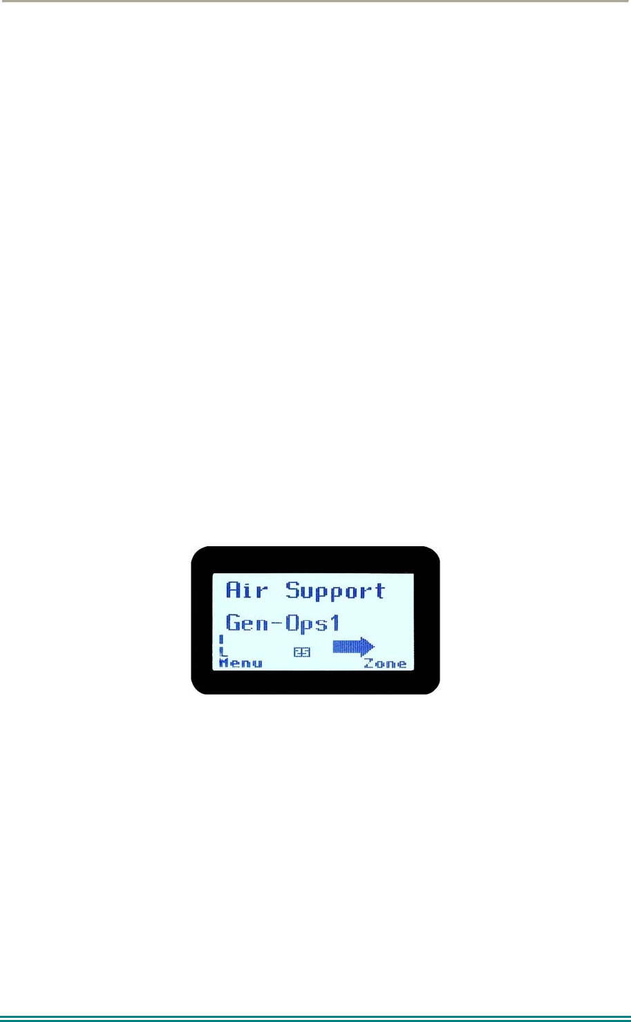
The top line of the display still shows the name of the current selected channel. The second
line of the display shows the name of the current selected zone while scanning/voting.
The channel can be changed by using the ▼ and ▲ keys. Other channels may be either
Scan or Normal channels, depending on the radio’s configuration.
Scanning/Voting is indicated by a rotating arrow symbol.
`

SRP9170/80 P25 Portable Radio – User Manual
© ComGroup Australia 2010 Page 50 TNM-U-E-0091 1.4a
When stopped on a channel, the second line from the top shows the name of the channel
from the scan group that the radio stopped on. If stopped on a channel, that channel can be
“skipped” by pressing the skip programmed function key. Once a channel is “skipped” it will
not be scanned for the duration that Zone/Channel selection.
While stopped on a channel, the asterisk (*) icon will display.
When transmitting on a channel, the second line of display shows the name of the current
channel that the radio is transmitting on.
5.1.12 Keypad Lock
The Keypad Lock function prevents accidental key presses.
The keypad lock function is enabled by the Field Programmer during configuration. If this
function is activated, a key icon will be displayed in the bottom right-hand side of the display
when locked.
The PTT, Alarm Key (if assigned), Reset Key (if assigned) are not locked.
To unlock the keypad, it is necessary to press and hold down the “OK” key for 2 seconds.
After 2 seconds, the key icon will disappear and the keys will be enabled.
The keypad will automatically re-lock after a period of 10 seconds following no key activity.
5.1.13 Encryption
In P25 Digital mode, radio channels may be programmed for encryption.
The encryption state of the selected channel is determined by the radio configuration. An
encrypted channel will display the encryption icon.
A radio channel that has been programmed for encryption will receive either clear or
encrypted traffic. A transmission on this channel will be encrypted.
The encryption icon will not be shown if a received signal is not encrypted when on an
encrypted channel.
The current channel’s transmit encryption key can be temporarily changed from the Crypto
menu.
When in Analogue FM mode, there is a simple voice inversion scrambler for low security
applications.
A double beep will sound at the start of each PTT.
The scrambler function key is assigned using the Field Programmer.

SRP9170/80 P25 Portable Radio – User Manual
© ComGroup Australia 2010 Page 51 TNM-U-E-0091 1.4a
5.1.14 Emergency Alarm
5.1.14.1 Receiving Emergency Calls
When an emergency call is being received, a message will be displayed on the default
screen “RxEm” indicating the radio unit sending the emergency call.
5.1.14.2 Making an Emergency Call
When the emergency key is pressed and held for a time determined by the FPP, the radio
will change to emergency mode. Under emergency mode, the radio can operate in three
FPP configurable modes:
Normal: The radio will continue to respond to PTT, channel change etc. while displaying the
E icon.
Frozen: The default screen will freeze, with the E icon displayed indicating emergency
mode.
Blank: The screen will blank giving no indication to others that the radio is in emergency
mode.
When emergency mode is triggered, the radio can be configured by the FPP to transmit and
receive on a cyclic basis with FPP programmed time periods. The display will show “TX
Em”:Channel No.
During TX, the radio will generate an emergency broadcast call on either the currently
selected channel or an FPP nominated channel.
Others may listen to the automatic transmissions to hear conversations near the radio.
Turning the radio off and on will disable emergency mode.

SRP9170/80 P25 Portable Radio – User Manual
© ComGroup Australia 2010 Page 52 TNM-U-E-0091 1.4a
6 SPECIAL FUNCTION KEYS
Several function keys are simply short cuts to a menu screen. Further information on the
operation of these function keys is contained in section 4.
6.1 ALARM
This key is used to put the radio into Emergency Mode.
Alarm is supported in Digital mode only.
Pressing the Alarm key send causes the radio to set the Emergency flag in the transmit voice
messaging and depending on radio configuration, optionally enter Transmit/Receive cycle
mode. In cycle mode, the radio will transmit live microphone audio at high gain for the
nominated duration and return to receive mode for the nominated duration.
This cycle will repeat indefinitely or until the radio is turned off and on again.
6.2 ANNOUNCE
To send an Announce call on the channel, press this function key and then use the PTT to
send the call. The next PTT after the Announce will call the default group.
6.3 CHANNEL UP AND DOWN
The current selected zone’s channel is decremented whenever the key is pressed.
The channel up and down functions are normally assigned to the Up/Down function keys.
They can be assigned to other keys if required.
If the current channel is the first channel, then the decremented channel will wrap around to
the last channel in the current zone.
The new channel can be an analogue or digital channel.
If pressed and held, the function auto repeats and updates the display for every 5th channel.
If the Talkaround function is enabled and selected, then Talkaround will be cancelled when
the channel is changed.
6.4 CRYPTO
The function provides a shortcut to the Encryption select menu for user selection of the
current encryption key.
6.5 DTMF SEND 1/2 (P25 ANALOGUE)
This function transmits a predefined DTMF sequence of up to 16 DTMF tones. There are
two DTMF send functions, DTMF1 and DTMF2.
Send DTMF is only supported in analogue mode and can be assigned to keys F1 to F6.
If an analogue channel is selected and transmit is allowed, then activating this function
transmits a predefined DTMF sequence (up to 16 tones).
6.6 KEY LOCK
The Keyboard Lock function is dedicated to the “OK” key. To use Key Lock, the function
has to be enabled in the FPP. To unlock the keys, the “OK” key must be held down for 2
seconds. The keys will then autolock again 10 seconds after no user activity.
Keys are locked in this mode with the exception of Emergency, PTT and any function key
that has been assigned Reset function.

SRP9170/80 P25 Portable Radio – User Manual
© ComGroup Australia 2010 Page 53 TNM-U-E-0091 1.4a
6.7 LOW POWER
This function forces the radio to low power transmit operation. Pressing the function key
again puts the radio back to the power level defined for the current channel. The “forced low
power state” is not affected by channel/zone changes.
The RF power level is indicated by the letter L of H replacing the antenna icon when
transmitting. The bar graph above this icon shows 1 bar for low power and 6 bars for high
power.
6.8 MENU
Menu function key used for accessing the menu system. This is normally assigned to the
“M” key (F1).
6.9 MODE
This function is a short cut to the Mode menu. The Mode menu is used to change radio
modes, such as P25 conventional to MPT1327 Trunked.
Selections: Network 1-5. These networks may be PMR, MPT1327 Trunked, P25
Conventional or P25 Trunked.
Mode is supported in analogue and digital modes.
Once pressed, the radio screen will display the Network menu. The user can then use the
▼ / ▲ keys to select the network and then press “OK”. The screen will then return to the
channel screen of the new mode.
6.10 MUTE
This function allows the radio Carrier-Mute level to be adjusted.
Supported in analogue mode only.
This function is a shortcut to Mute Adjust menu.
On an analogue Channel, the mute level can be adjusted between the FPP Minimum Mute
and maximum mute limits.
6.11 RESET
The reset function performs several tasks.
In order of priority, it:
Stops Alerts (if any Alerts are sounding).
Performs a Backspace (if there is a User entry pending).
Switches back to the Main Menu (if in a lower menu) .
It is used during text entry modes such as Phonebook Edit and Text Messaging for
backspacing.
6.12 SCAN
The Scan key starts and stops the Scan mode on a channel that has been associated with a
scan list and enabled for scanning. Scanning will be indicated to the user with a rotating
arrow icon.
Scan is supported in both analogue and digital mode.
If scan is enabled for the current channel in the current zone and auto scan is not enabled,
then start scanning the channels defined in the current channel’s scan group.
The 2nd press of the scan key will turn scanning off.

SRP9170/80 P25 Portable Radio – User Manual
© ComGroup Australia 2010 Page 54 TNM-U-E-0091 1.4a
Note that if Autoscan is programmed for that channel, the Scan key will not function.
6.13 SCAN EDIT
This key is used to enter the Scan Edit menu, where the members of a scan group can be
added or deleted.
6.14 SCRAMBLER (P25 ANALOGUE)
This function enables transmitted voice to be scrambled, to prevent radios without a
scrambler from listening in on the conversation.
This low security form of encryption is sufficient to make speech unintelligible to other casual
listeners, however it does not offer high level security as other radios programmed with a
scrambler function will be able to unscramble it.
Supported in analogue mode only.
The speaker sounds a ‘bip-bip’ tone when PTT is pressed to indicate that scrambler is active.
Scrambler On/Off state is reset to Off at power-up and channel change.
First press of the function key enables scrambler mode.
The 2nd press restores channel to normal (clear) mode.
6.15 SKIP
The Skip function key is used to temporarily remove members from a scan channel. The
removal is temporary only until the channel is changed.
6.16 SQUELCH
The squelch mode is used to selectively receive P25 signals. It has three modes, Monitor,
Normal and Selective. When set to Monitor, all P25 traffic on that channel will be heard,
subject to presence of encryption. Normal mode will hear all P25 traffic with the correct NAC
code. Selective mode will only receive calls to the channel default talkgroup and individual
calls.
6.17 TALKAROUND
On a repeater channel only, this function key allows the radio to transmit on the base
station’s output channel, so the user can talk directly to other mobiles on the channel, while
the repeater is out of service or out of range.
When the key is pressed again (or the Channel is changed) the mobile’s transmitter channel
reverts to its normal setting.
Talkaround mode is indicating to the user by a double beep at the start of each PTT.
6.18 ZONE
This function provides a shortcut to the detailed zone menu.

SRP9170/80 P25 Portable Radio – User Manual
© ComGroup Australia 2010 Page 55 TNM-U-E-0091 1.4a
7 ACCESSORIES
The following accessories are available for the SRP9180 portable radio. Contact your
Simoco Dealer for further information.
7.1 LITHIUM ION BATTERY (PAR-9180BATL2X)
Capacity of 2200 mAh, non Intrinsically safe battery.
7.2 LITHIUM ION BATTERY (PAR-9180BATL2)
Capacity of 2200 mAh. Intrinsically Safe – must be used with Intrinsically Safe version of
radio for radio to be Intrinsically Safe.
7.3 LITHIUM ION BATTERY (PAR-9180BATL3X)
Capacity of 3000 mAh, non Intrinsically safe battery.
7.4 LITHIUM ION BATTERY (PAR-9180BATL3)
Capacity of 3000 mAh. Intrinsically Safe – must be used with Intrinsically Safe version of
radio for radio to be Intrinsically Safe.
7.5 SINGLE POCKET CHARGER (PAR-9180CRG1)
Charger capable of charging one portable radio at a time.
7.6 TWO POCKET CHARGER (PAR-9180CRG2)
Charger for two portable radios.
7.7 SIX POCKET CHARGER (PAR-9180CRG6)
Charger for up to six portable radios.
7.8 VEHICLE MOUNTED CHARGER (PAR-9180CRGV)
Charger for in vehicle charging of the portable.
7.9 LIGHTWEIGHT CARRY CASE (PAR-9180CLBC2)
Carry case for light duty use with PAR-9180BATL2/i. This carry case MUST be used with
Intrinsically Safe radios.
7.10 LIGHTWEIGHT CARRY CASE (PAR-9180CLBC3)
Carry case for light duty use with PAR-9180BATL3/i. This carry case MUST be used with
Intrinsically Safe radios.
7.11 HEAVY DUTY CARRY CASE (PAR-9180CHSM)
Carry case for heavy-duty use with belt loop attachment.
7.12 LIGHTWEIGHT LAPEL FUNCTION SPEAKER MICROPHONE (PAR-9180LMS2)
Combined small speaker and microphone for light duty use incorporating two programmable
function keys.
7.13 FOUR FUNCTION SPEAKER MICROPHONE (PAR-9180LMS4)
Combined medium duty speaker and microphone incorporating four programmable function
keys.
7.14 FOUR FUNCTION ANTENNA SPEAKER MICROPHONE (PAR-9180LMR4)
Combined medium duty speaker and microphone incorporating four programmable function
keys and radio antenna.
7.15 GPS MICROPHONE (PAR-9180LMGM)
Speaker Microphone incorporating GPS receiver for tracking applications and four
programmable function keys.

SRP9170/80 P25 Portable Radio – User Manual
© ComGroup Australia 2010 Page 56 TNM-U-E-0091 1.4a
7.16 EARPIECE (PA-LMEP8)
Earpiece for portable radio.
7.17 PROGRAMMING LEAD (MAR-9180PRLDU
USB programming lead for configuring radio personality using Field Personality Programmer.
7.18 BELT CLIP (PAR-9180CLIP)
Belt Clip for belt widths of up to 50mm. The clip screws onto the rear of the battery.
7.19 STUD MOUNT (PAR-9180STUD)
Klickfast Stud for the Klickfast range of quick docking portable radio attachment options.

SRP9170/80 P25 Portable Radio – User Manual
© ComGroup Australia 2010 Page 57 TNM-U-E-0091 1.4a
8 ALERT TONES AND MESSAGES
Tone Type: Tone: Meaning:
Grant 0.03s, (1000Hz) Grant Tone
Denied 0.4s, (440Hz) Denied Tone
Ring 8 short beeps 5s(silence) repeat After receiving individual
call
Missed Call 2 short beeps 10s (silence)
repeat
Missed individual call
Page 3 short high tones Received Page
Missed Page 2 short beeps 10s(silence) repeat A page was sent.
Figure 3 – Alert Tones

SRP9170/80 P25 Portable Radio – User Manual
© ComGroup Australia 2010 Page 58 TNM-U-E-0091 1.4a
9 GLOSSARY
A summary of common radio terms and some other terms used in this document, and their
meanings, are given below.
Term Description
Bank See Zone
Channel A logical combination of
Network Access Code (NAC)
RF Frequency
Default TalkGroup Identity (TGID)
Encryption Key Index (KID)
Other channel associated parameters (CTCSS, scan etc)
DTMF Dual Tone Multi Frequency
FPP Field Personality Programmer or Field Programmer - Used for configuring the
radio options and parameters
FM Frequency Modulation
LED Light Emitting Diode
Monitor Mode of Radio Receive - Any P25 signal regardless of NAC or TGID will be
heard
MPT Trunked MPT1327 Trunked Mode
NAC Network Access Code - Used as a filter where multiple networks may share a
common RF frequency
Normal Mute Mode of Radio Receive - Only signals with matching NAC will be heard.
P25 Channel Definition consisting of TX and RX RF frequencies, NAC and TGID
P25 Conventional Non-trunked digital, like digital PMR
PMR Private Mobile Radio
PTT Push To Talk
Radio Unit ID Unique identifier allocated to each radio (0-16,000,000)
RF Radio Frequency
RSSI Received Signal Strength Indication
RX Receive
Selective Mode of radio receive - Only signals with matching NAC and TGID or Unit ID

SRP9170/80 P25 Portable Radio – User Manual
© ComGroup Australia 2010 Page 59 TNM-U-E-0091 1.4a
will be heard
TX Transmit
WACN Wide Area Coverage Network
Zone A collection of channels (usually organised by functional group of users)

SRP9170/80 P25 Portable Radio – User Manual
© ComGroup Australia 2010 Page 60 TNM-U-E-0091 1.4a
10 COMPLIANCE WITH RF ENERGY EXPOSURE GUIDELINES
(UNITED STATES AND CANADA)
RF ENERGY EXPOSURE AWARENESS AND CONTROL INFORMATION AND OPERATIONAL
INSTRUCTIONS FOR FCC OCCUPATIONAL USE REQUIREMENTS.
Before using your Simoco portable two-way radio, read this important RF energy awareness and
control information and operational instructions to ensure compliance with the FCC’s RF exposure
guidelines.
NOTICE: This portable radio is intended for use in Occupational/ Controlled conditions in
applications where users have full knowledge of their exposure and can exercise control over
their exposure to meet FCC limits. This radio device is NOT authorised for general population,
consumer, or any other use.
This portable two-way radio uses electromagnetic energy in the radio frequency (RF) spectrum to provide
communications between two or more users over a distance. It uses radio frequency (RF) energy or radio waves
to send and receive calls. RF energy is one form of electromagnetic energy. Other forms include, but are not
limited to, electric power, sunlight and x-rays. RF energy, however, should not be confused with these other forms
of electromagnetic energy, which when used improperly can cause biological damage. Very high levels of x-rays,
for example, can damage tissues and genetic material.
Experts in science, engineering, medicine, health and industry work with organizations to develop standards for
exposure to RF energy. These standards provide recommended levels of RF exposure for both workers and the
general public. These recommended RF exposure levels include substantial margins of protection. All two-way
radios marketed is North America are designed, manufactured and tested to ensure they meet government
established RF exposure levels. In addition, manufacturers also recommend specific operating instructions to
users of two-way radios. These instructions are important because they inform users about RF energy exposure
and provide simple procedures on how to control it. Please refer to the following websites for more information on
what RF energy exposure is and how to control your exposure to assure compliance with established RF
exposure limits.
http:l/www.fcc. gov/oet/rfsafety/rf-fags. htm 1
http://www.osha.gov/SLTC/radiofrequencvradiation/index.htmi
Federal Communications Commission Regulations:
The FCC rules require manufacturers to comply with the FCC RF energy exposure limits for portable
two-way radios before they can be marketed in the U.S. When two-way radios are used as a
consequence of employment, the FCC requires users to be fully aware of and able to control their
exposure to meet occupational requirements. An exposure awareness label is attached to the
equipment directing users to specific awareness information.
Compliance with RF Exposure Standards
Your Simoco portable two-way radio is designed to comply with a number of national and international
standards and guidelines (listed below) regarding human exposure to radio frequency electromagnetic
energy. This radio complies with the IEEE (FCC) and ICNIRP exposure limits for Occupational/
Controlled RF exposure environment at duty factors of up to 50% talk 50% listen and is authorised by

SRP9170/80 P25 Portable Radio – User Manual
© ComGroup Australia 2010 Page 61 TNM-U-E-0091 1.4a
the FCC for occupational use. In terms of measuring RF energy for compliance with the FCC exposure
guidelines, your radio radiates measurable RF energy only while it is transmitting (during talking), not
when it is receiving (listening) or in standby mode.
Your Simoco two-way radio complies with the following RF energy exposure standards and guidelines:
United States Federal Communications Commission, Code of Federal Regulations; 47CFR
part 2 sub-part J
American National Standards Institute (ANSI) / Institute of Electrical and Electronic Engineers
(IEEE) C95. 1-1992
Institute of Electrical and Electronic Engineers (IEEE) C95.1-1999 Edition
Industry Canada RSS-102

SRP9170/80 P25 Portable Radio – User Manual
© ComGroup Australia 2010 Page 62 TNM-U-E-0091 1.4a
RF Exposure Compliance and Control Guidelines and
Operating Instructions
To control exposure to yourself and others and ensure compliance with the Occupational/ Controlled
environment exposure limits always adhere to the following procedures.
Guidelines:
User awareness instructions should accompany the device when transferred to other users.
This radio meets the FCC RF exposure guidelines when used with the Simoco accessories
supplied or designated for the product. The designated Simoco belt clip type is PAR-
9180CLIP and leather pouches for bodyworn use are Simoco types PAR-9180CLBC2 and 3,
and PAR-9180CHSM with extension speaker microphone type PAR-LMS2. Use of other
accessories may not ensure compliance with the FCC’s RF exposure guidelines and may
violate FCC regulations.
Do not use this device if the operational requirements described herein are not met.
Instructions:
Transmit no more than the rated duty factor of 50% of the time. To transmit (talk), push the
Push-To-Talk button. To receive calls, release the PTT button. Transmitting 50% of the time,
or less, is important because this radio generates measurable RF energy exposure only when
transmitting (in terms of measuring for standards compliance).
Do not operate the radio without an approved antenna attached, as this may cause the FCC
RF exposure limits to be exceeded. With this product, use only an antenna supplied or
approved by Simoco.
Always keep the radio at least 5 cm (2.0 inches) from the face when transmitting and at least
10 mm (0.4 inches) from the body. This radio has been tested for RF exposure compliance at
the distances listed in Table 1.

SRP9170/80 P25 Portable Radio – User Manual
© ComGroup Australia 2010 Page 63 TNM-U-E-0091 1.4a
Table 1: RF Exposure Compliance Distances
FREQUENCY Bodyworn Handheld in front of
face
136-174MHz 10mm (0.4 inches) 25mm (1.0 inches)
400-480MHz 10mm (0.4 inches) 25mm (1.0 inches)
440-512MHz 10mm (0.4 inches) 25mm (1.0 inches)
Approved Accessories
To obtain a list of other Simoco approved accessories see contact details below or visit the
following website which lists approved accessories: www.simoco.com.au
Contact Information
For additional information on exposure or other information, please contact:
ComGroup Australia
1270 Ferntree Gully Road
Scoresby
Victoria, 3179
Australia
Telephone +61 3 9730 3800
Facsimile +61 3 9730 3968
Email simoco@simoco.com.au
Website www.simoco.com.au