SimonsVoss Technologies 01 Door Lock User Manual SV1C User Manual US
SimonsVoss Technologies, Inc. Door Lock SV1C User Manual US
Manual

Cylindrical RF Lock SV1C
State of: December 2006

SV1C Cylindrical RF Lock
Page 2
1.0 Important Information....................................................................3
2.0 Operation.........................................................................................4
2.1 General Information ............................................................................ 4
2.2 Opening and Locking From Outside.................................................. 4
2.3 Opening and Locking From Inside..................................................... 5
3.0 Additional Functions......................................................................5
3.1 OMRON................................................................................................. 5
3.2 Extending the Unlock Time ................................................................ 5
3.3 Logging Unauthorized Access Attempts .......................................... 5
3.4 No Acoustic Programmer Acknowledge ........................................... 5
4.0 Battery Warnings............................................................................6
4.1 RF Lock ................................................................................................ 6
4.2 Transponder ........................................................................................ 7
5.0 Battery Replacement......................................................................7
6.0 Installation Instructions.................................................................8
6.1 General Information ............................................................................ 8
6.2 Unpack Pack........................................................................................ 9
6.3 Mark Door........................................................................................... 10
6.4 Drill Door............................................................................................ 11
Install Latch Unit.......................................................................................... 12
Install Lock ................................................................................................... 13
6.5 Install Outside Components............................................................. 13
6.5 Install Outside Components............................................................. 14
Install Inside Components .......................................................................... 15
C. Strike Installation (Wood Frame Only)............................................. 16
6.6 Troubleshooting ................................................................................ 17
6.7 Programming the RF Lock................................................................ 17
6.8 Perform Function Test ...................................................................... 17
7.0 Data Sheet.....................................................................................18

SV1C Cylindrical RF Lock
Page 3
Important Information
Safety remark:
Caution! – Incorrect handling of the batteries and storage batteries used in
this product can result in the risk of fire or burns. Do not charge, open or
burn these batteries or heat them to more than 100 °C (212 °F).
Installation of a SimonsVoss RF Lock requires knowledge in the areas of door
mechanics, door certifications, installation of electronics and the use of the
SimonsVoss software. For this reason, only trained and authorized personnel should
install the unit.
Compliance Statement (Part 15.19)
This device complies with Part 15 of the FCC Rules.
Operation is subject to the following two conditions:
1. This device may not cause harmful interference, and
2. This device must accept any interference received,
including interference that may cause undesired operation.
Warning (Part 15.21)
Changes or modifications not expressly approved by the party responsible for
compliance could void the user’s authority to operate the equipment.
FCC Interference Statement (Part 15.105 (b))
This equipment has been tested and found to comply with the limits for a Class B
digital device, pursuant to Part 15 of the FCC Rules. These limits are designed to
provide reasonable protection against harmful interference in a residential
installation. This equipment generates uses and can radiate radio frequency energy
and, if not installed and used in accordance with the instructions, may cause harmful
interference to radio communications. However, there is no guarantee that
interference will not occur in a particular installation. If this equipment does cause
harmful interference to radio or television reception, which can be determined by
turning the equipment off and on, the user is encouraged to try to correct the
interference by one of the following measures:
- Reorient or relocate the receiving antenna.
- Increase the separation between the equipment and receiver.
- Connect the equipment into an outlet on a circuit different from that to which the
receiver is connected.
- Consult the dealer or an experienced radio/TV technician for help.
Industry Canada Statement per Section 4.0 of RSP-100
The term "IC:" before the certification / registration number only signifies that the
Industry Canada technical specifications were met.
Section 7.1.5 of RSS-GEN
Operation is subject to the following two conditions:
1) this device may not cause harmful interference, and
2) this device must accept any interference received, including interference that may
cause undesired operation.
SimonsVoss Technologies Inc. will not accept any liability for damages caused by
incorrect installation.
SV1C Cylindrical RF Lock
Page 4
An incorrectly installed RF Lock may block the access through a door. SimonsVoss
Inc. is not liable for the consequences of incorrect installation, such as blocked
access to injured or endangered persons, property damage or other damages.
If you will be storing the RF Lock for more than one week, remove the backup battery.
1.0 Operation
1.1 General Information
The SV1 Digital RF Lock is an ANSI Grade 1 lock and can easily be installed in any
door prepared according to the ANSI/BHMA A156.2-1996 standard. In comparison to
standard mechanical locks, this RF lock is just as easy to install, provides greater
security, is more flexible and costs less to operate..
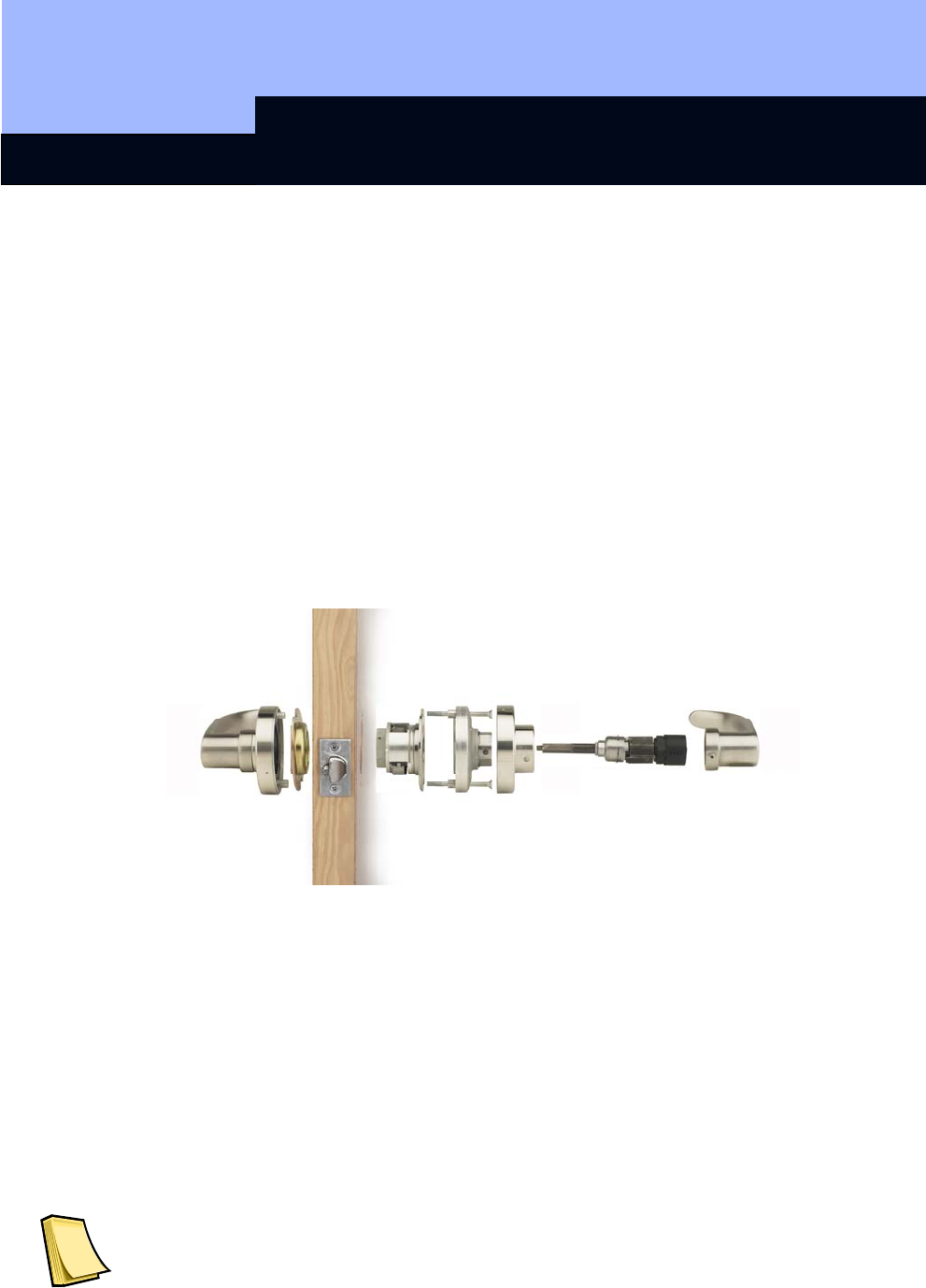
Inner handle
Outer handle
1.2 Opening and Locking From Outside
When locked, the outer lever turns freely, not engaging the latch. It is not possible to
open the door from the outside. Hold the transponder at a distance of approximately 4
to 16 inches (10 to 40 cm) from the RF lock and briefly press the transponder button
once. If this is an authorized transponder, a double signal tone sounds and the lock
engages the latch. Now turn the outer lever. You have approximately three seconds
for this process. You can use the software to increase the unlock time if needed. The
longer the unlock time, the shorter the service life of the battery. After the specified
unlock time has expired, a single signal tone sounds and the outer lever turns freely
again.
If this transponder is not authorized at this time because of the time zone plan, a
single signal tone sounds, but the RF lock does not engage or unlock and you cannot
open the door.

SV1C Cylindrical RF Lock
Page 5
1.3 Opening and Locking From Inside
It is always possible to open doors with the SV1 RF Lock from the inside without
operating the transponder
2.0 Additional Functions
You can activate the following functions with the software settings:
2.1 OMRON
All product versions can be operated in OMRON mode. You will find a detailed
description in the Smart Relay manual.
2.2 Extending the Unlock Time
The default unlock-time for the RF Lock is approximately 3 seconds. You can use the
software to extend this time to approximately 10 seconds. This shortens the lifetime of
the battery.
2.3 Logging Unauthorized Access Attempts
For RF Lock version 10.2 and later, it is possible to log unauthorized access attempts,
as well as authorized accesses. This includes both access attempts without
authorization and access attempts outside the specified time zone. In this connection,
however, only transponders from the same lock system are logged, which means that
the transponder must have the same lock system ID (SID).
2.4 No Acoustic Programmer Acknowledge
When programming over the network, it can be desirable to deactivate the acoustic
programmer acknowledge. You can do that with this function.

SV1C Cylindrical RF Lock
Page 6
3.0 Battery Warnings
3.1 RF Lock
Warning level 1 for main battery
If the main battery of the lock goes empty, eight short signal tones, coming quickly
one after another, sound after you operate the transponder and before the cylinder
unlocks. You must replace both batteries now.
Warning level 2 for backup battery (SW Version 10.0 & SW Version 10.1)
In addition to the main battery warning, an additional eight short signal tones, coming
quickly one after another, now sound for the backup battery warning. The RF Lock
does not unlock until after the signals. From now on, the backup battery is active. You
must replace both batteries as soon as possible.
Warning level 2 for backup battery (SW Version 10.2 and later)
Now the signal tones of the backup battery warning sound for only approximately 30
seconds (without the main battery warning). The RF Lock does not couple until after
the signals. From now on, the backup battery is active. You must replace both
batteries as soon as possible.
Warning level 3 (SW Version 10.2 and later)
If you continue to ignore this backup battery warning, either the door can be used 50
more times or the RF Lock switches off after 4-5 weeks if there is no further
operation. In both cases, the lock switches into the so-called storage mode. After this,
you can only open the lock with the programming device.
SV1C Cylindrical RF Lock
Page 7
3.2 Transponder
If the transponder battery voltage is getting low, eight short signal tones, coming
quickly one after another, sound each time the transponder is operated on the lock
after the unlock.
Do not take out the transponder battery because this will probably result in
the loss of data. See the “Transponder” manual for more information.
4.0 Battery Replacement
Only authorized personnel are permitted to replace the battery. Use only batteries
that are approved by SimonsVoss.
Twist the inner rose so that the access hole is aligned with the latch and exposing the
set-screw.
Use a 7/32 Hex key to remove the set-screw being careful to hold the inner handle so
that it does not fall off. Set the inner handle aside along with the set-screw.
Twist the battery just a few degrees counter clockwise as you are looking at the inside
of the door. The cap then slides off exposing the batteries.
Remove both batteries and replace them with the new batteries in the same
orientation. The two batteries are inserted with the largest sides (positive terminals)
facing each other and the smaller sides (negative terminals) facing out.
Reversing the polarity can result in damage to the lock. Incorrect handling of
the batteries used in this device can result in the risk of fire or burns. Do not
charge, open, heat to more than 100 C (212 C) or burn. Replace the batteries
only with original batteries supplied by SimonsVoss.
Please dispose of lithium batteries immediately when discharged. Store
away from children, do not open and do not throw into fire.
SV1C Cylindrical RF Lock
Page 8
Replace the battery cap by aligning it so that it slides on easily and then twist a few
degrees in the clockwise direction until it locks in place.
If the inner rose was removed, replace it so the access hole is lined up to allow the
replacement of the set-screw. Use a 7/32 Hex key to replace the set-screw being
careful to hold the inner handle so that it does not fall off.
When the set-screw has been tightened down (finger pressure), rotate the inner rose
so that the access hole is facing down concealing the set-screw..
You must reprogram the lock after the battery change because the clock does
not work without power (Software Operating Instructions: Programming >
Setting the Clock on the Lock).
5.0 Installation Instructions
5.1 General Information
When installing the SimonsVoss RF Lock, make sure that there are no sources of RF
interference in the vicinity. You should install these locks at least 1.5 feet (0.5 m)
from other RF locks or SmartRelays at a distance of at least 5 feet (1.5 m).
Attention Installer
If Installation instructions are not followed this may result in damage to the lock and
void the factory warranty.
The SimonsVoss SV1 Cylindrical RF Lock is designed to fit the ANSI/BHMA A156.2-
1996 door preparation standard. If the door has not been prepared you will need the
following tools:
2 1/8” (54mm) hole saw for the main cylindrical hole
1” (25mm) boring bit for the latch
5/16” (8mm) drill bit for the lock through-bolt screws
7/64” (2.5mm) drill bit for the latch mounting screws
Chisel and hammer to create the inset for the latch
32 Phillips screw driver to mount the lock
3/8” or ½” drill
Important: The accuracy of the door preparation is critical for the proper
function and security of this lever handle lock. Misalignment can cause pre-
mature wear and tear and a lessening of security.
SV1C Cylindrical RF Lock
Page 9
5.2 Unpack Pack
A. Remove the lock components from the box.
SV1C Cylindrical RF Lock
Page 10
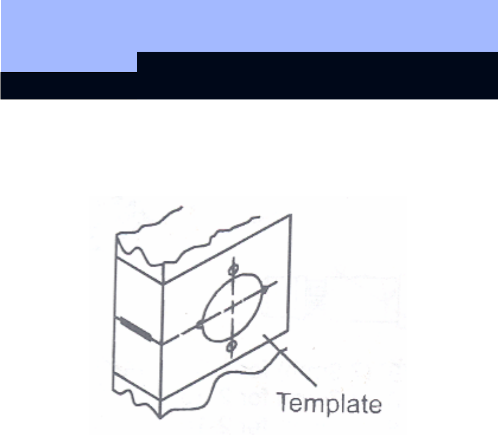
5.3 Mark Door
Mark horizontal line across edge of door 40 5/16” (1024mm) is standard height from
floor. Fold template over edge of door, centering on horizontal line. Mark centers of
holes at proper backset.
SV1C Cylindrical RF Lock
Page 11
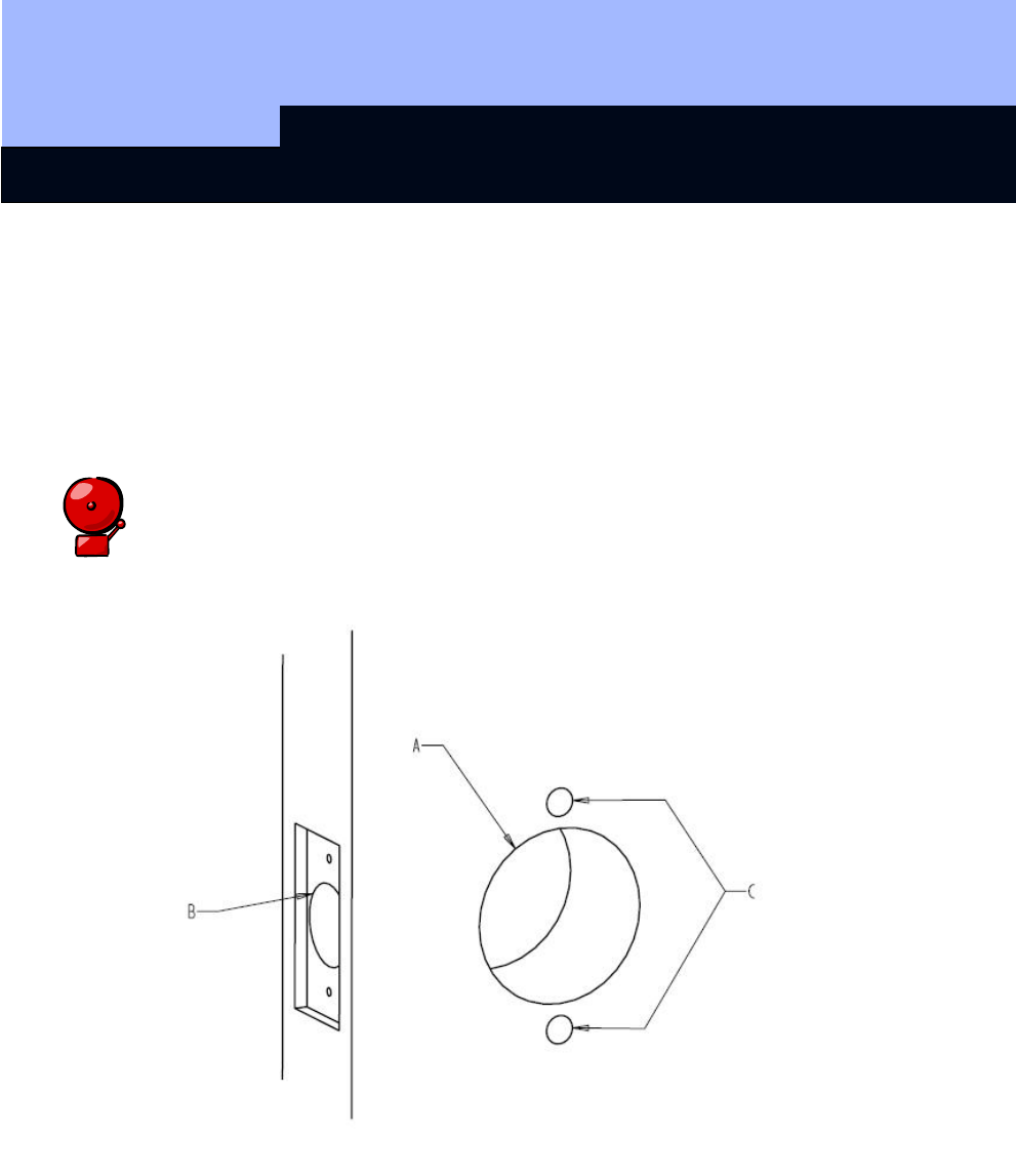
5.4 Drill Door
A. Drill 2 1/8” (54mm) diameter hole through the door.
B. Drill 1” (25mm) diameter hole in edge of door. Cut out for latch front 1 1/8” (29mm)
wide by 2 ¼” (57mm) high by 5/32” (4mm) deep. Check latch unit for proper width
front and square or round corners.
C. Drill two (2) 5/16” (8mm) diameter holes through door.
Caution:
To avoid splintering wood drill holes through both sides of door.
SV1C Cylindrical RF Lock
Page 12
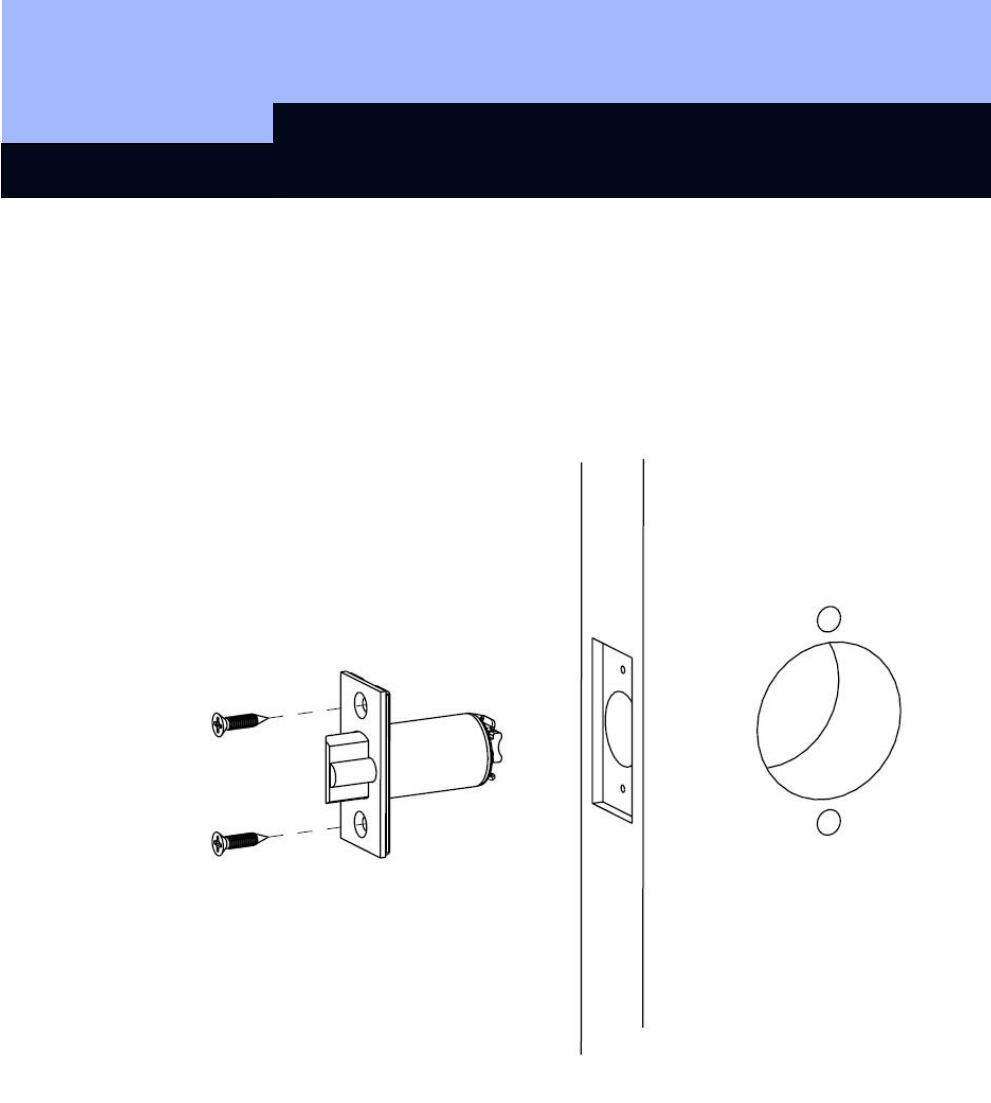
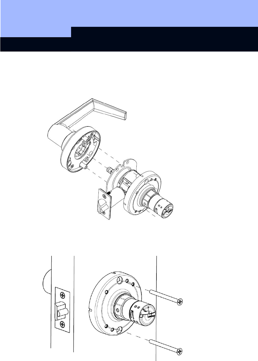
Install Latch Unit
Insert latch unit in door.
(Be sure bevel edge of bolt faces strike plate.) Attach with two screws supplied.
SV1C Cylindrical RF Lock
Page 13
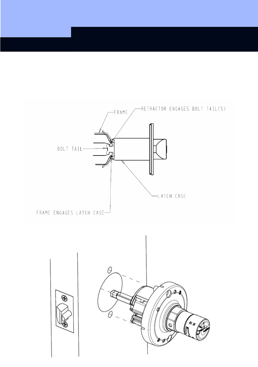
Install Lock
Insert the inside rose support assembly into door from inside making sure that lock
body frame hooks latch case and retractor engages bolt tail(s). DO NOT FORCE (If
lock body does not engage latch easily, check door preparation for errors.)
SV1C Cylindrical RF Lock
Page 14
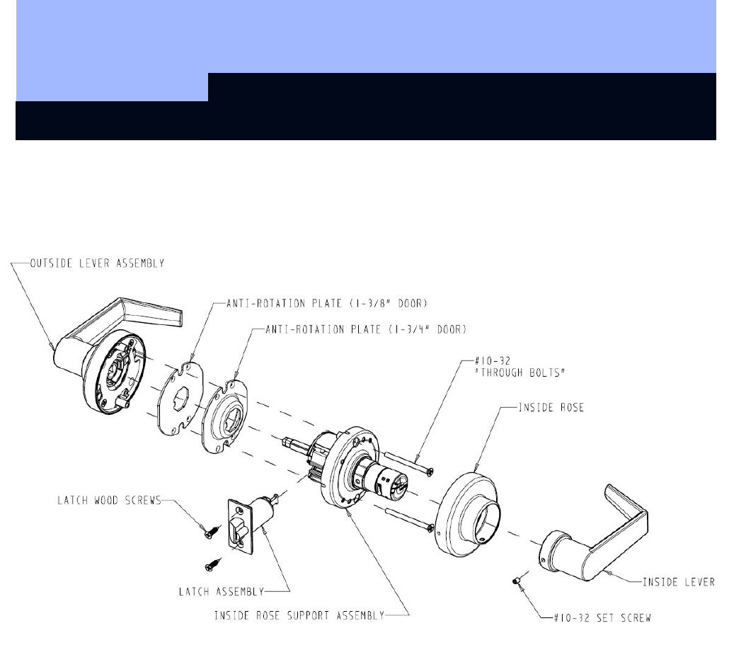
Install Outside Components
A. Choose and install the anti-rotation plate on the outside of the door. For a 1 ¾” door
use the deep plate. For a 1 3/8” door use the flat plate.
B. With the battery arrow pointing up on the inside, slide the outside lever assembly onto
the lock shaft. Fasten rose assembly with two through bolts from the inside.
SV1C Cylindrical RF Lock
Page 15
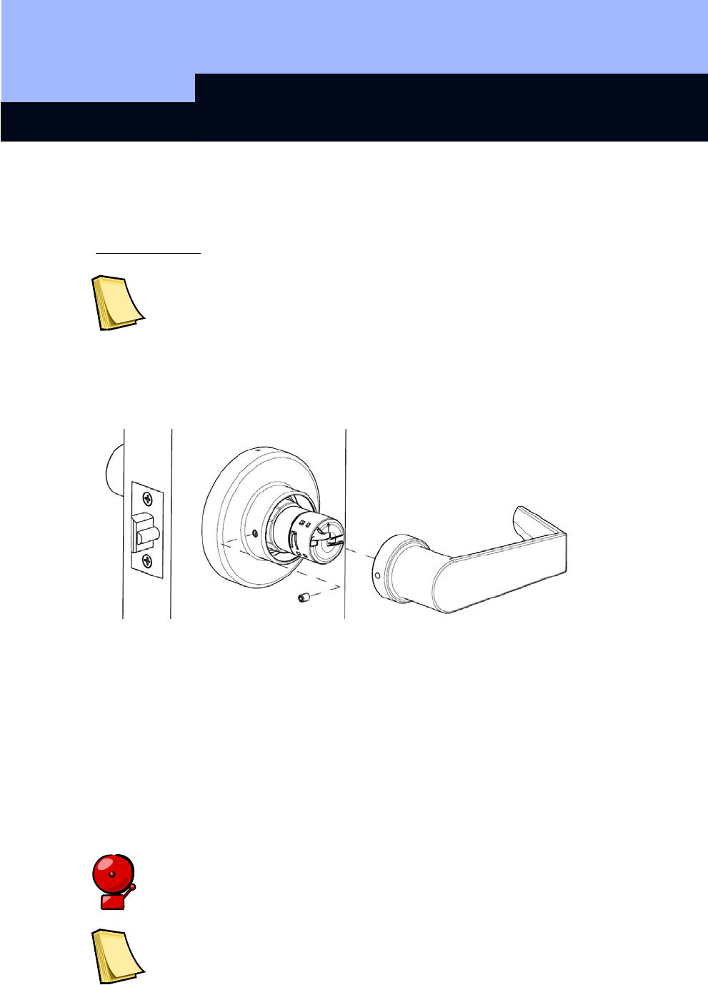
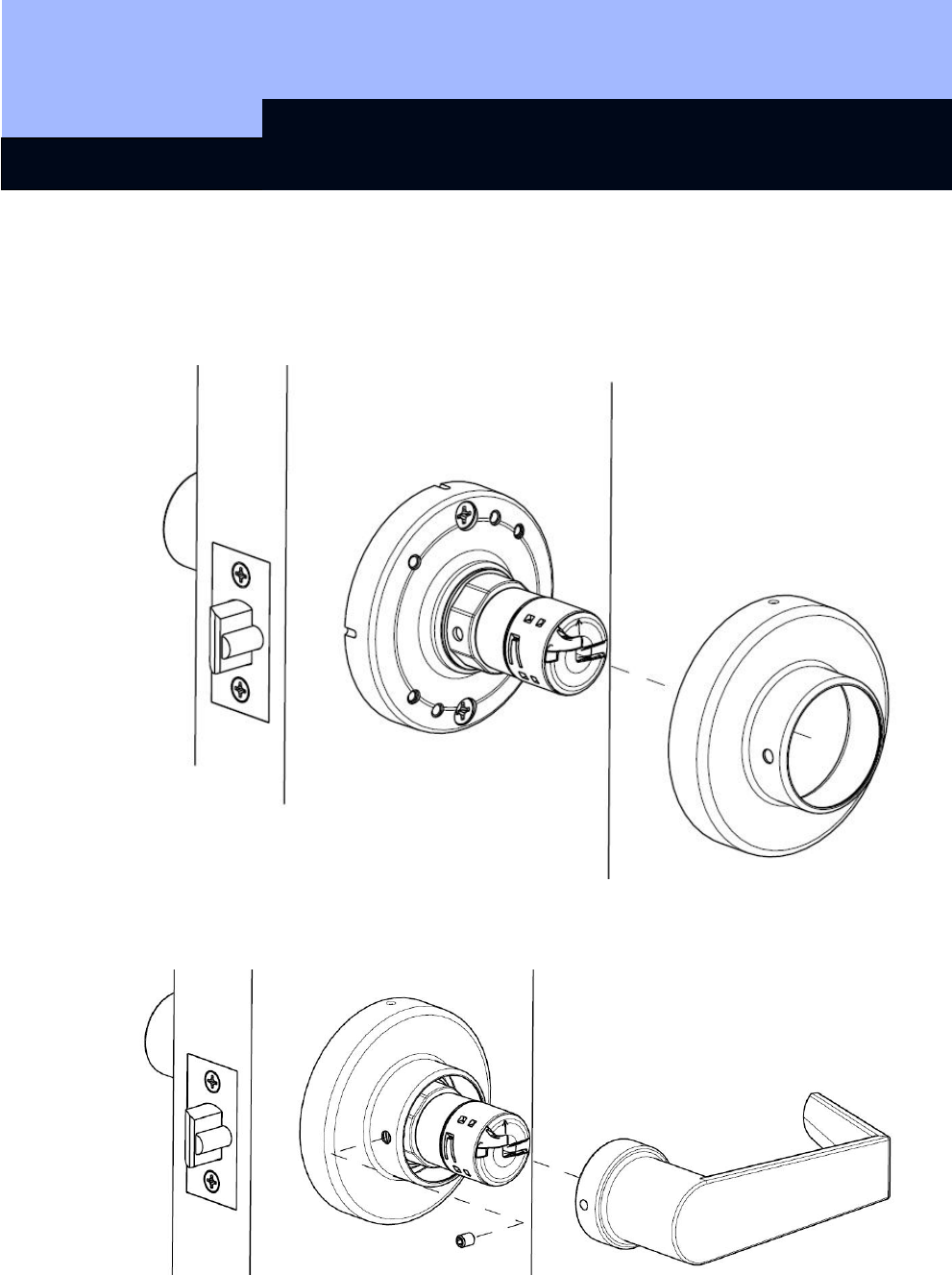
Install Inside Components
A. Place rose on inside rose support assembly so that the side hole points towards the
shut face of the door. Snap into place against the door.
B. Install the inside lever handle. Fasten inside lever handle with setscrew inserted in
the side hole of the inside rose.
C. Rotate the rose so that the side hole faces down. The rose will snap in to place.
SV1C Cylindrical RF Lock
Page 16
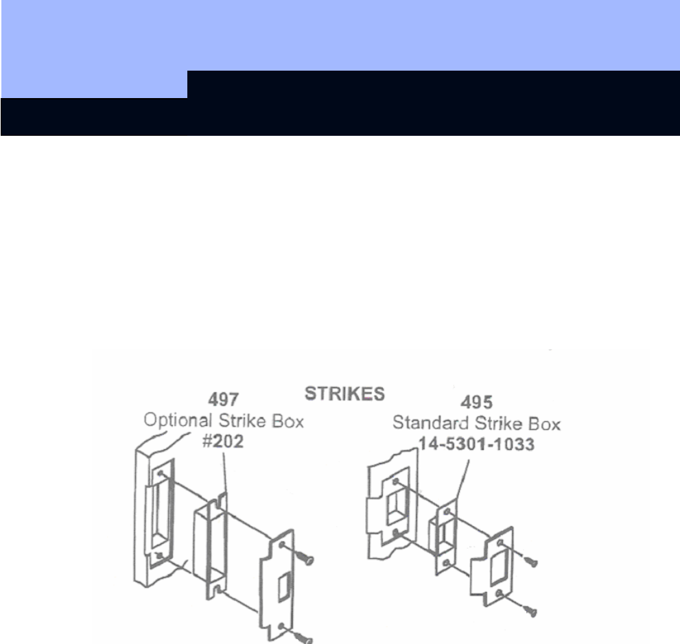
Strike Installation (Wood Frame Only)
A. Close door and mark a horizontal line from the center of the template to the frame of
the door.
B. Measure half the thickness of the door; mark this same distance with a vertical line
starting from the stop side of the frame and where both lines cross make a 1” (25mm)
diameter hole and 1/2” (13mm) in depth.
C. Align the holes of the strike with the vertical line, trace the outline of the strike and
mortise to 1/16” (1.6mm) depth. Attach the strike with two screws (provided).

SV1C Cylindrical RF Lock
Page 17
5.5 Troubleshooting
1. Check door.
2. Check hinges. They should not be loose or have excessive wear on knuckles.
3. Latch will not deadlock. Either strike is out of line or gap between door and
jamb is too great. Realign strike or shim out towards flat area or latch.
4. Latch does not retract or extend properly. Latch tail and retractor not properly
positioned.
i. Remove lockset. Look through 2 1/8 hole and verify latch tail centered
between top and bottom of hole.
ii. Remove latch and insert lockset, look through latch hole and verify re-
tractor mouth centered in hole. Adjust outside rose plate if not.
iii. Re-bore holes if necessary to line up retractor and tail.
5.6 Programming the RF Lock
You must program the SimonsVoss SV1 Cylindrical RF Lock and accompanying
transponders in the lock plan software before you install them. Please refer to the
Software Operating Instructions for more detailed information.
The SimonsVoss RF Locks are delivered in storage mode, which means that no
communication is possible with the transponder. You can use software and the
programming device to remove the storage mode. Please refer to the Software
Operating Instructions for more detailed information.
5.7 Perform Function Test
1. With the door open, turn the inner lever. The lever must move easily.
2. Close the door and repeat the process. If the latch or lock is stiff, you probably
need to align the door or correct the strike plate.
3. Then perform the same test on the outer lever. To do this, operate an
authorized transponder near the lock.
SV1C Cylindrical RF Lock
Page 18
6.0 Data Sheet
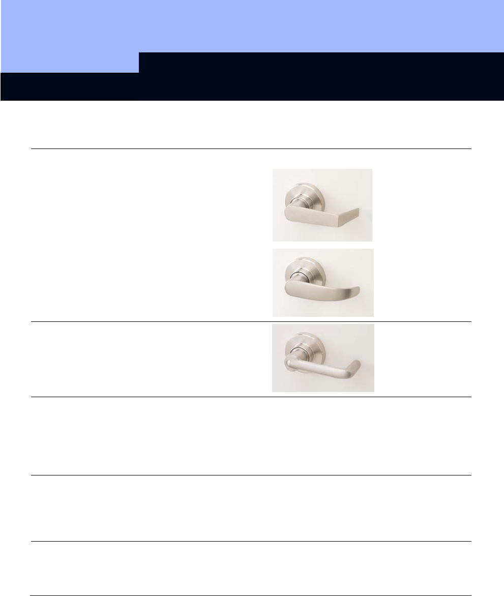
Levers Material Stainless steel
Styles
Castle
Manor
Harbor
Finishes 630 Satin Stainless Steel
629 Bright Stainless Steel
606E Satin Brass
605E Bright Brass
619E Satin Nickel
613E Satin Oil-Rubbed Bronze
Battery Type
Service life
(2) Lithium 3 V, CR2450
Use only original replacement batteries
from SimonsVoss
Approx. 100,000 operations,
or 4 years Standby
Environmental
Conditions Operating temperature
Storage temperature
Enclosure
-4°F to +122°F (-20°C to +50°C)
-31°F to +158°F (-35°C to +70°C)
IP54 (when installed)