SimonsVoss Technologies 04 Lock Switch User Manual Manual SmartRelay US
SimonsVoss Technologies, Inc. Lock Switch Manual SmartRelay US
UserManual.wiki
>
SimonsVoss Technologies
>
04 User Manual
Manual
Navigation menu
Upload a User Manual
Namespaces
Wiki Guide
HTML
PDF
Info
Views
User Manual
Discussion / Help
Navigation
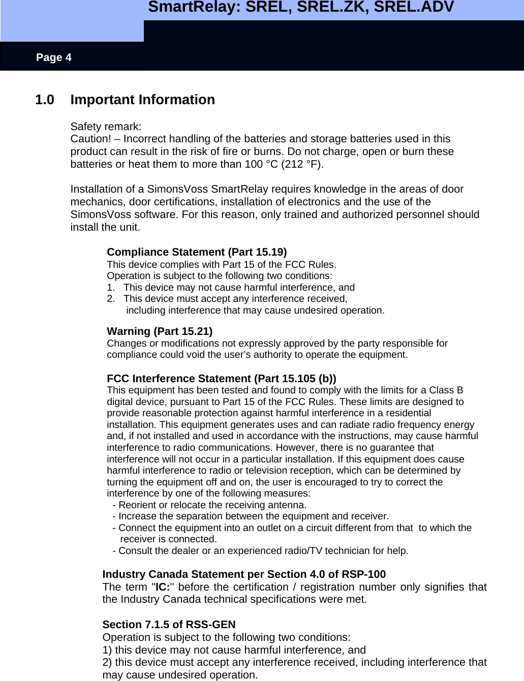
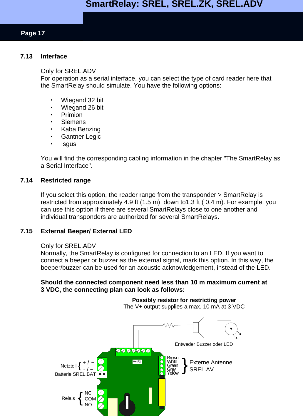
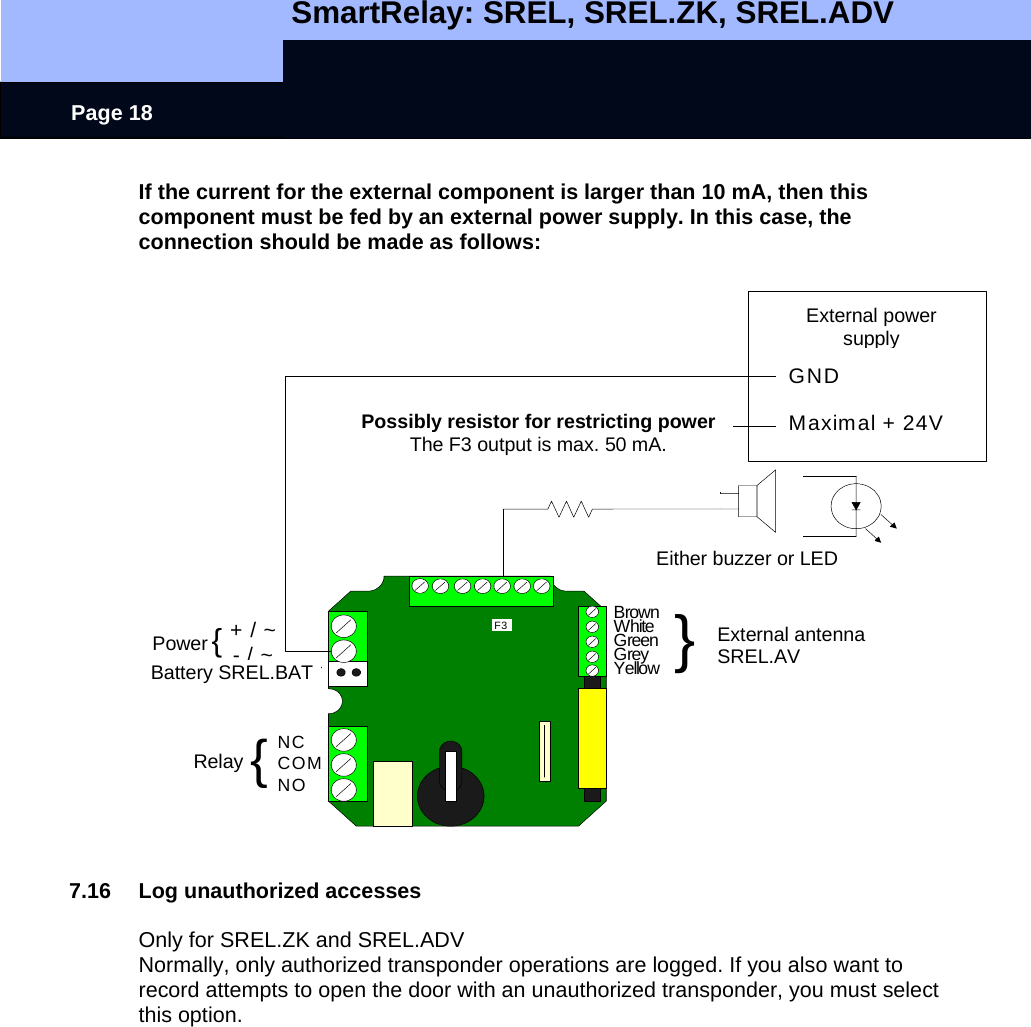
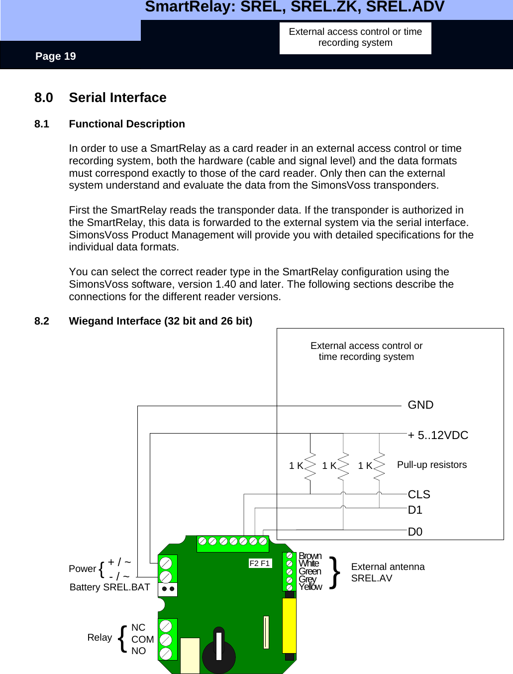
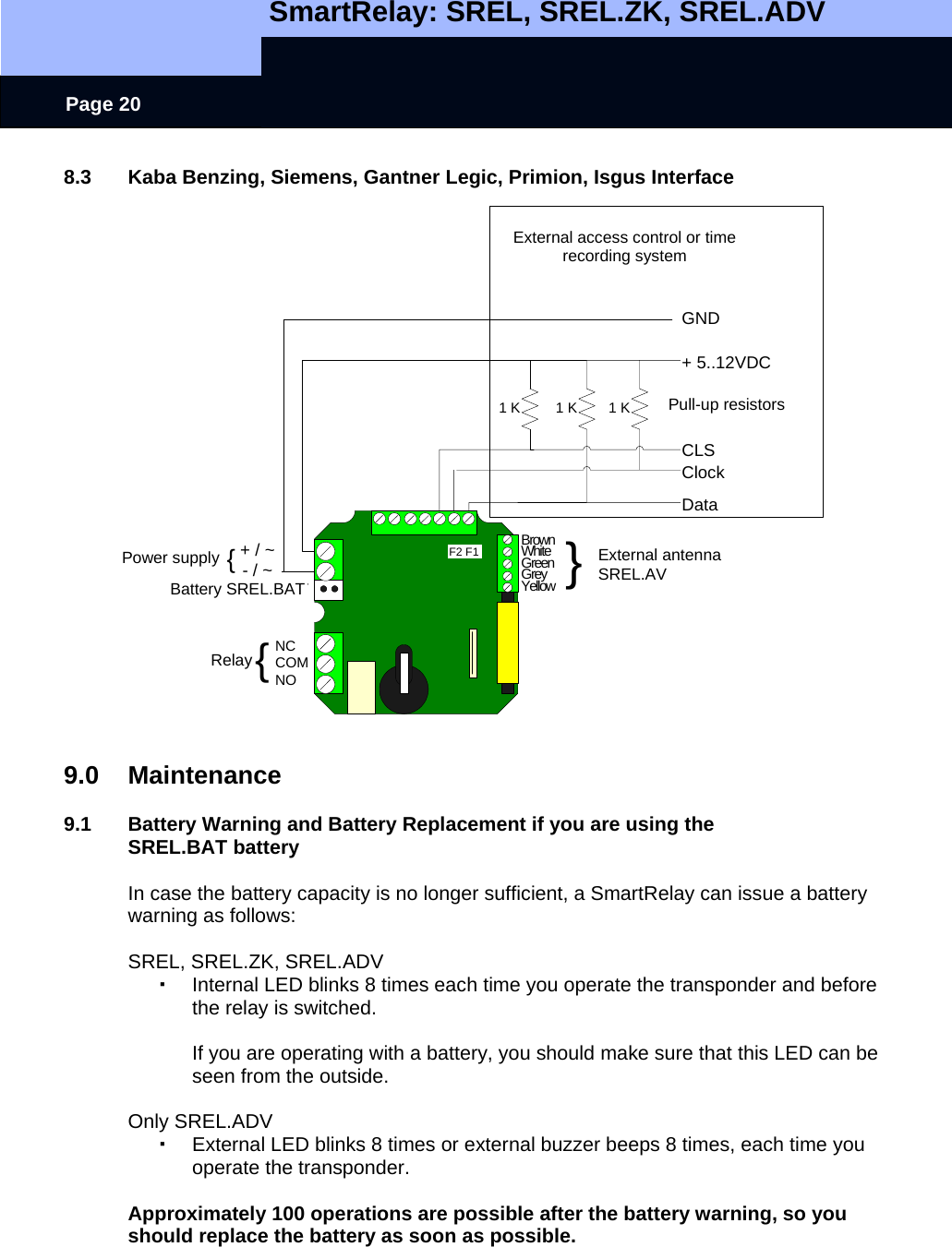
![SmartRelay: SREL, SREL.ZK, SREL.ADV Page 22 10.0 Data sheet Housing made of black plastic: Dimensions [LxWxH] 72 x 57 x 25.5 mm (approximately 2.8 x 2.2 x 1.0 inches) Degree of protection IP 20 (NEMA1), not tested for outside use Temperature Operation at: -31°F to +131°F (-22°C to +55°C) Storage at: 32°F to +104°F (0°C to +40°C) Air humidity <95% without moisture condensation Printed circuit board dimensions [LxWxH] 50 x 50 x 14 mm (approximately 2.0 x 2.0 x 0.6 inches) Line voltage 12 VAC or 5-24 VDC (no reverse voltage protection) Power limit Power supply must be limited to 15 VA Quiescent current < 5 mA Max. current < 100 mA Programmable pulse width 0.1 to 25.5 seconds Output relay type Change-over Output relay continuous current Max. 1.0 A Output relay switch on current Max. 2.0 A Output relay switching voltage Max. 24 V Output relay switching capacity 106 operations at 30 VA Multifunction connections: F1, F2, F3 Max. 24 VDC, max. 50mA Vibrations 15G for 11 ms, 6 shocks according to IEC 68-2-27 Not released for continuous used under Vibrations](https://usermanual.wiki/SimonsVoss-Technologies/04/User-Guide-744423-Page-22.png)