Simplex Time Recorder 300301 Wireless Smoke Detector User Manual 300 301 Smoke detector
Simplex Time Recorder Company Wireless Smoke Detector 300 301 Smoke detector
Contents
- 1. Users Manual
- 2. User manual
Users Manual

P/N 300.MAN Rev. 1.0
2006 Commercial Wireless Systems International, LLC
1
Smoke Detector with Transmitter
Models 300/301
Description:
The Models 300/301 are self-contained photoelectric type smoke detectors with a built in
sounder and transmitter. The detectors comply with UL 268 and are designed to provi
de
open area protection. The transmitter is fully supervised for tamper, low battery
,
chamber
sensitivity and RF signal integrity. The internal sounder can also be turned on remotely by
the CP-3000 FACP (model 301 only). The smoke detector is powered by a single 3 volt
lithium battery as listed under the specifications section of this manual and the label on the
product. The Model 300 is intended to be used with Commercial Wireless Systems
International, LLC Model CP-3000 Fire Alarm Control Panel. Refer to the CP-3000 FACP
installation instructions, part number 3000.MAN Rev. 1 for additional details.
IMPORTANT:
Smoke detectors must be tested and maintained regularly following NFPA
72 requirements. At a minimum, cleaning should be performed annually.
Progra
mming:
The 300/301 must be enrolled into the CP-3000 Fire Alarm Control Panel before installing
the device. The Model 330 will not report Alarms, Supervisory or trouble signals
unless it is enrolled into the CP-3000 control panel. Enrollment must be perfor
med
while in front of the CP-3000 FACP. Place the CP-3000 FACP in enrollment mode then
install the battery in the smoke detector observing polarity
.
The model 300/301 serial
number will be displayed on the CP-3000 FACP along with programming options. Refer to
the CP-3000 control panel installation instructions for further details on enrollment and
transmitter programming options. After the model 300/301 is enrolled, remove the battery
and reinstall it only at the transmitters mounting location.
Installati
on:
Select an accessible location that is not prone to tampering or accidental damage.
The
Model 300/301 must be installed and maintained in accordance with the National Fire
Protection Association’s Standards (NFPA), the National Electrical Code
and
all l
ocal
fire and electrical requirements. The mounting surface should be relatively flat and
capable of accepting screws or anchors. The smoke detector is to be installed in an indoor
dry location. Exposure to weather or corrosive conditions may damage the un
it.
Perform
the signal test described in this manual prior to and after permanently mounting the
unit
.
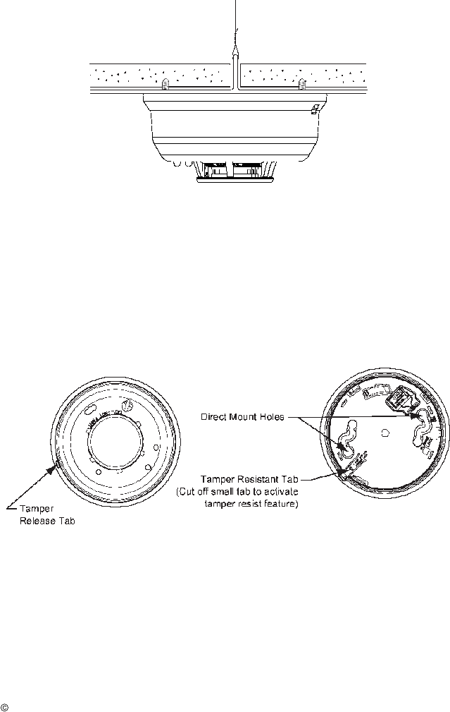
Note:
If the detector is mounted to a removable ceiling tile, the tile must be secured
with the appropriate fasteners to prevent tile removal
or mount th
e detector across a ceiling
panel support as shown in figure 1. First install the mounting bracket using the screws
supplied. Install the battery in the battery holder. The polarity is marked on the holder.
Attach he detector to the bracket by turning the detector in a clockwise direction until it
clicks into place. Wait for the green and red LED’s to indicate Standby condition (green
blinks every 10s and red off) then perform the signal test and fully test the unit for alarm as
described in
Alarm
Testing.
P/N 300.MAN Rev. 1.0
2006 Commercial Wireless Systems International, LLC
2
Figure 1
Proper Mounting to Ceiling Tile
Tamper
-
Resistant Feature
The smoke detector includes a tamper
-
resistant feature that prevents removal from the
mounting base without the use of a tool. To engage the tamper
-
resistant feature, cut the
smal
l plastic tab locate
d on the mounting base (Figure 2
), and then install the detector. To
remove the detector from the base once it has been made tamper resistant, use a small
screwdriver to depress the square tamper release tab, located on the skirt of the
mounting
base, and turn the detector counterclockwise.
Figure 2
Tamper Resistant Feature
Cautions:
1. Make sure the battery is firmly installed in the smoke detector battery compartment.
2. The unit must be secured tightly to the wall, so as to not
be dislodged.
3. Test the unit after any service, battery change or as often as local or national codes
dictate.

P/N 300.MAN Rev. 1.0
2006 Commercial Wireless Systems International, LLC
3
Do NOT Install Detectors in the Following Areas:
In or near areas where particles of combustion are normally present such as
kitchens; in
garages; near furnaces, hot water heaters, or gas space heaters.
In very cold or very hot areas.
In wet or excessively humid areas, or next to bathrooms with showers.
In dusty, dirty, or insect
-
infested areas.
Near fresh air inlets or returns or excessive
ly drafty areas.
Consult NFPA 72, the local Authority Having Jurisdiction (AHJ), and/or applicable codes for
specific information regarding the spacing and placement of smoke detectors.
Operation:
Led status indicators
and Sounder
The 300/301 detectors are equipped with two
LED
’s
status indicators and a sounder
to
provide local visual and audible indication of the detector’s status
. The table below explains
the LED
and sounder
functions.
LED Status and Sounder Operation
Condition
Green LED
Red LED
Sounde
r
Transmitted Signal
to CP
-
3000
Power up
Blink every
5s for 20s
Blink every
5s for 20s
Off
None
Standby
Blink
every 10s
Off
Off
Test (check in)
every 90s
Alarm
Off
On Steady
Temporal pattern
Alarm
Test Switch
P
ressed
Off
On Steady
Temporal pattern
None
Maintenance
or Fault
Off
Blink
every 5s
Off
Maintenance
Required Trouble
Every 90s
Tamper
Blink
every 10s
Off
Off
Tamper Trouble
Every 90s
Low Battery
Off
Blink
every 45s
Chirp every 45s
after LED blinks
for
2
days
Low Battery
Trouble Every 90
s
Alarm
Operation
:
When the detector senses smoke the Green LED extinguishes, the Red LED turns on
steady, the internal sounder
turns on in
the temporal pattern and the following occurs:
1
. An initial alarm signal is transmitted
.
2. A 30 second delay
occurs. If during this delay the alarm condition is reset, a restore
signal is sent ending the alarm cycle.
3. The continued alarm condition causes a repeat alarm transmission.
4. Another 30 second delay as in step 2 occurs.
5. The continued alarm cau
ses a level 2 repeat alarm transmission.
6. Step 5 repeats at 60 second intervals until reset.

P/N 300.MAN Rev. 1.0
2006 Commercial Wireless Systems International, LLC
4
Tandem
Sounder Feature Model 301 only
The model 301 has
a
feature which allows the smoke detectors piezo sounder to be turned
on
or off in tandem with an RF
command
signal
from the CP-3000 control panel.
This
enables an installation to be programmed so that when an alarm is received from
any
smoke detector sensing smoke the CP-3000 control panel can activate the sounder in one
or more smoke detectors that hav
e
not sensed smoke. When activated, the sounder will
turn on in the temporal pattern. Note: Only the smoke detector sensing smoke will
transmit an alarm signal.
This
feature must be programmed into the CP-3000 Control
Panel to
function
. Refer to the CP
-
300
0 manual for additional information and programming
instruction.
If the detector is in alarm due to smoke detection the tandem silence signal
from the control panel will not silence the sounder. If the detector is in alarm due to smoke
detection and it receives the tandem on signal the sounder will remain active even if smoke
clears from the chamber.
A tandem silence signal will be required to turn off the sounder.
Alarm Testing
Detectors must be tested after installation and following maintenance or batte
ry
replacement.
NOTE: Before testing, notify the proper authorities that maintenance is
being performed and the system will be temporarily out of service. Place the CP-
3000
control panel in test to prevent any unwanted alarms (refer to the CP-3000 manual).
Perform both A and B below to properly test the 300/301 detector. If a detector fails any of
the tests below, it should be cleaned as outlined in the Maintenance section. If the detector
still fails, it should be replaced.
A. Test Switch
Note: This test
will
only function if
the
detector
is operating within its proper sensitivity limits
and not in a low battery condition
.
The purpose of this test is to check the functionality of the circuitry. It will not cause an
alarm signal to be transmitted.
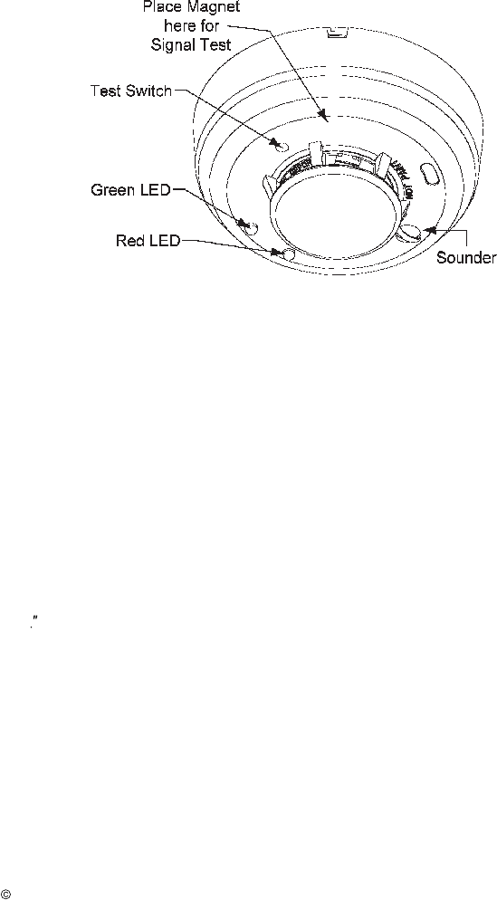
1. An o
pening for the recessed test switch is located on
the detector housing. (Figure 3
)
2. Insert a small screwdriver or allen wrench (
0.18
max.) into the test switch opening; push
and hold for 5 seconds then release.
3. If the detector is within the listed sensitivity limits, the following should occur:
a. The green LED turns off.
b. The red LED turns on steady.
c. The sounder activ
ates with the temporal pattern.
4. Perform step B below.
B. Smoke Entry Test
Note:
This test
will
cause an alarm signal to be transmitted.
1. Using canned smoke detector tester or hold a smoldering punk stick or cotton wick at the
side of the detector a
nd gently blow the smoke through the detector until it alarms.
2. Verify the alarm signal was received at the control panel.
3. If both test A+B pass, remove the panel from test mode (Refer to the CP-3000 manual)
and
notify the proper authorities when
the system is back in service.
P/N 300.MAN Rev. 1.0
2006 Commercial Wireless Systems International, LLC
5
Figure 3
LEDS, Sounder, Test Switch and Signal Test Locations
Signal Test:
The test must be performed while the smoke detector is held in its intended mounting
location. Initiate the test by placing a strong magnet on the smoke detector housing at the
location shown in figure 3. The model 300/301 piezo sounder will beep twice if the
transmitter is located within acceptable reception range of a repeater or CP-3000 FACP. If
two beeps are not heard within 5 seconds of initiating the signal test then relocate the
model 300/301 mounting position closer to the nearest repeater or control panel and
perform the test again. Continue this procedure until 2 beeps are achieved. Do not mount
the smoke detector unless 2 beeps are heard when performing the signal test. This test
must
be performed before and after transmitter installation. Note: A CWSI model AR-3
repeater or
CP
-
3000
Control Panel must be installed and turned on before running this test.
Test Switch Functi
ons:
This switch has multiple functions and is located in an opening on the detector housing as
shown in figure 3. To activate the switch insert a small screwdriver or allen wrench
(0.18
max.) into the test switch opening; push and hold for 5 seconds. Pressing this switch
will not cause an alarm at the control panel.
The functions of the Test Switch are:
1. Test the functionality of the detectors circuitry when pressed while
the
detector is in
standby
.
2.
Silence the low battery chirp for 12 hours if pres
sed during low battery.
3. Silence the detector sounder for 5 minutes if pressed anytime while the sounder is
turned on in the temporal pattern.

P/N 300.MAN Rev. 1.0
2006 Commercial Wireless Systems International, LLC
6
Low battery:
The
model 300/310
smoke detector
tests for a low battery condition once every 65 minutes.
Th
e battery voltage has to be at or below 2.7V nominally for two consecutive low battery
tests before a low battery
trouble
condition is
transmitted
.
When a low battery is detected
the green LED will turn off, the red L
ED
will blink every 45 seconds and a
lo
w battery
trouble signal will be
transmitted
and repeated every 90 seconds. Once the low battery
condition is present for 2 days, the piezo sounder will begin to chirp once every 45
seconds
.
This gives the service person time to replace the battery prior to audible
notification.
The
low battery trouble signal will be
transmitted
and the piezo sounder will
chirp for an additional 7 days before the unit shuts down all operations.
Pressing the smoke
detector test button will silence the sounder chirp for 12 hours however the low battery
trouble signal will continue to be transmitted every 90 seconds. Where more than one type
of trouble exists, all will be repeated in increments of
90
seconds. Always replace the
battery with a new one. Refer to the Battery Installation and Replacement section for
instructions on battery replacement.
Battery Installation and Replacement:
Warning:
Always install a new battery of one of the approved types as listed in the
Specifications section of this manual and the product label. When a battery is first
inserted, a low battery test is performed. If the battery passes the test, the LED’s should
indicate normal standby.
If the battery does not pass this test, the unit gives no indication of
operation
and the
LEDs do not blink at all
and a fresh battery should be installed
.
To replace the battery:
1. Place the CP-3000 Control Panel in Test mode to prevent any unwanted alarms. (Refer
to the CP
-
3000 manual)
2. Remove the detector from its mounting base by twisting the detector count
erclockwise.
Remove the battery and dispose of properly. If the Tamper Resistant feature was
implemented during installation then follow the instructions under that section for
removing
the detector.
3. To insure proper power down sequence, wait a minimum of 20 seconds before installing
a new battery.
4. Install a new approved 3 volt lithium battery in the battery compartment following the
polarity diagram inside the compartment. A tamper trouble signal should be indicated on
the CP
-
3000 Control Panel
upo
n installation of the new battery
.
5. Reinstall the smoke detector onto the mounting base by turning the detector clockwise.
6. The LED’s should indicate Power up and then N
ormal
Standby conditions as shown in
the LED status and sounder table.
7. Test the detector for alarm operation as described in the
Alarm
Testing
section of this
manual.
8. If the detector does not function as described in items 6+7 then start over at step 2. If it
still doesn’t operate correctly then replace the entire unit.
9.
Rem
ove the panel from test mode. (Refer to the CP
-
3000 manual)
P/N 300.MAN Rev. 1.0
2006 Commercial Wireless Systems International, LLC
7
Tamper:
The Models 300/310
contain
a built in contact that will cause a tamper signal to be
transmitted if the detector is removed from its mounting position. Upon detect
or
removal
, a
tam
per signal is
transmitted
and repeated every
90
seconds until the detector is mounted
on its base. Where more than one type of trouble exists, all will be repeated in increments
of 90
seconds.
Maintenance / Fault:
The
Models
300/301 contain circuitry that allows the detector to automatically adjust its
sensitivity back to the factory setting when it becomes more sensitive due to contaminants
settling in its chamber. If the sensitivity has shifted outside the listed limits the Green LED
will extinguish, the Red LED will flash every 5 seconds and a maintenance required signal
wil
l be sent and repeated every 90 seconds until the condition is corrected. Perform
maintenance on the detector as described in this manual. If the problem persists, replace
the detect
or.
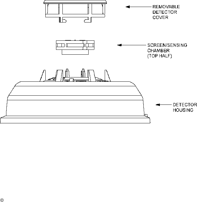
Figure 4 Removing Screen/Sensing Chamber

P/N 300.MAN Rev. 1.0
2006 Commercial Wireless Systems International, LLC
8
Maintenance
Perform maintenance yearly or whenever a Maintenance Req. Trouble signal is indicated.
Warning: Never remove the tamper proof screws attaching the detector cover to the
chassis containing the circuit boards
.
The chamber is accessible without removing
the cover.
NOTE: Before performing maintenance on the detector, notify the proper authorities that
maintenance is being performed and the system will be temporarily out of service. Pla
ce
the control panel in test to prevent any unwanted alarms.
The battery must be removed from the detector before performing maintenance of any kind.
1.
Place the CP-3000 Control Panel in Test mode to prevent any unwanted alarms. (Refer
to the CP
-
3000 man
ual)
2
. Remove the detector by turning counterclockwise
and remove the battery
.
3.
To insure proper power down sequence, wait a minimum of 20 seconds before removing
chamber top.
4. Remove the chamber cover by turning it counterclockwise.
3
. Vacuum t
he
chamber
cover or use canned air to remove any dust or debris.
4
. Remove the top half of the screen/sensing chamber by lifting straight up. (F
igure 4
)
5. Vacuum or use canned air to remove any dust or particles that are present on both
chamber halves.
6. Replace the top half of the screen/sensing chamber by aligning the arrow on the
screen/sensing chamber with the arrow on the housing. Press down firmly until the
screen/sensing chamber is fully seated.
7. Replace the
chamber
cover by placing it over the screen/sensing chamber and turning it
clockwise until it snaps into place.
8. Reinstall the battery.
9. Reinstall the smoke detector onto the mounting base by turning the detector clockwise.
10. Test the detector for alarm operation as described in t
he
Alarm
Testing
section of this
manual.
11. If the detector does not function as described in item 10 then start over at step 2. If it
still doesn’t operate correctly then replace the entire unit.
12. Remove the panel from test mode. (Refer to the CP
-
30
00 manual)

P/N 300.MAN Rev. 1.0
2006 Commercial Wireless Systems International, LLC
9
Specifications:
Battery Type: 3 Volt Lithium; Duracell DL123A, Sanyo CR123A, Panasonic
CR123A.
Battery Life: 12 Months Minimum
Battery Replacement: Upon Low battery report and/or during annual
maintenance.
Average Standby Current:
8.5ua
Average Alarm Current:
15ma
Tamper Switch: On base
Sounder: 85db at 10’ temporal pattern
Reset: Automatic
Sensitivity: 2.5% nominal
Low battery threshold: 2.7V
Operating Temperature Range: 32
F to +100
F.
Operating Humidity Range 0 to 95% RH.
Testing: Follow
this manual and
NFPA 72 or local requirements.
Transmission: In compliance with FCC part 15 for reception on equipment
manufactured by Commercial Wireless Systems International, LLC.
Test Transmission: Every 90
seconds.
Compatibility: Commercial Wir
eless Systems International, LLC Model CP
-
3000.
Mounting base diameter 5.30”
Weight 6.4 oz.
FCC Statement
Important: Any changes or modifications not expressly approved by the party responsible
for compliance could void the user’s authority to oper
ate the equipment
This device complies with part 15 of the FCC Rules. Operation is subject to the following
two conditions: (1) This device may not cause harmful interference, and (2) this device
must accept any interference received, including interference that may cause undesired
operation.

P/N 300.MAN Rev. 1.0
2006 Commercial Wireless Systems International, LLC
10
COMMERCIAL WIRELESS SYSTEMS INTERNATIONAL, LLC
ONE YEAR LIMITED WARRANTY
Commercial Wireless Systems International, LLC (“Seller”), 10794 N.W.
53 Street, Sunrise, Florida 33351, warrants this product to be free from
defects in workmanship for
two
years from date of purchase, under
normal use and service. Seller’s obligation is limited to repairing or
replacing, at it’s option, free of charge for parts and labor any part proven
to be defective in materials or workmanship. Seller shall have no
obligation under this warranty otherwise if: (1) the product is altered,
repaired or serviced by anyone other than the seller, (2) the product is
damaged from accidents, acts of God, misuse, tampering or abuse, (3)
pro
duct is not installed and operated in accordance with the instructions
provided by the seller. In case of defect, contact the fire alarm
professional who installed and maintains your fire alarm system or the
seller for product repair.
This two year Limited Warranty is in lieu of all other express warranties,
obligations, or liabilities. There are no express warranties that extend
beyond the face hereof. In no case shall seller be liable to anyone for
any consequential or incidental for breach of this or any other warranty,
express or implied, or upon any other basis of liability whatsoever, even
if the loss or damage is caused by the seller’s own negligence or fault.
Seller shall have no liability for any personal injury, property damage, or
other loss based on a claim that the product failed to operate correctly.
However, if the seller is held liable, whether directly or indirectly, for any
loss or damage arising under this warranty or otherwise, regardless of
cause of origin, Seller’s maximum liability shall not in any case exceed
the purchase price of the product, and shall be the complete and
exclusive remedy against the Seller.
NOTES

P/N 300.MAN Rev. 1.0
2006 Commercial Wireless Systems International, LLC
11