Simplex Time Recorder WRA3 WIRELESS FIRE ALARM PANEL User Manual
Simplex Time Recorder Company WIRELESS FIRE ALARM PANEL
UserManual.wiki
>
Simplex Time Recorder
>
WRA3 User Manual
User Manual
Navigation menu
Upload a User Manual
Namespaces
Wiki Guide
HTML
PDF
Info
Views
User Manual
Discussion / Help
Navigation
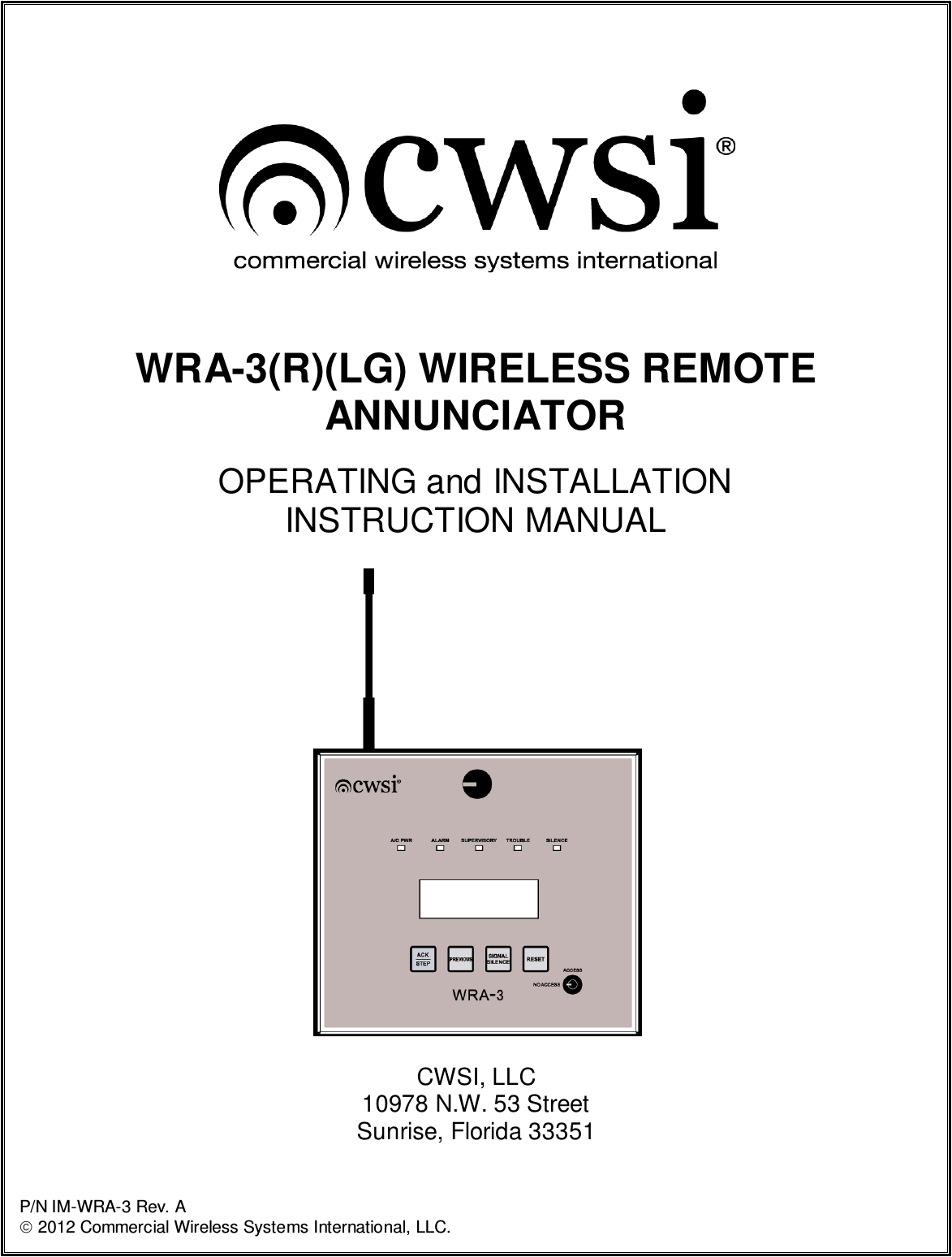
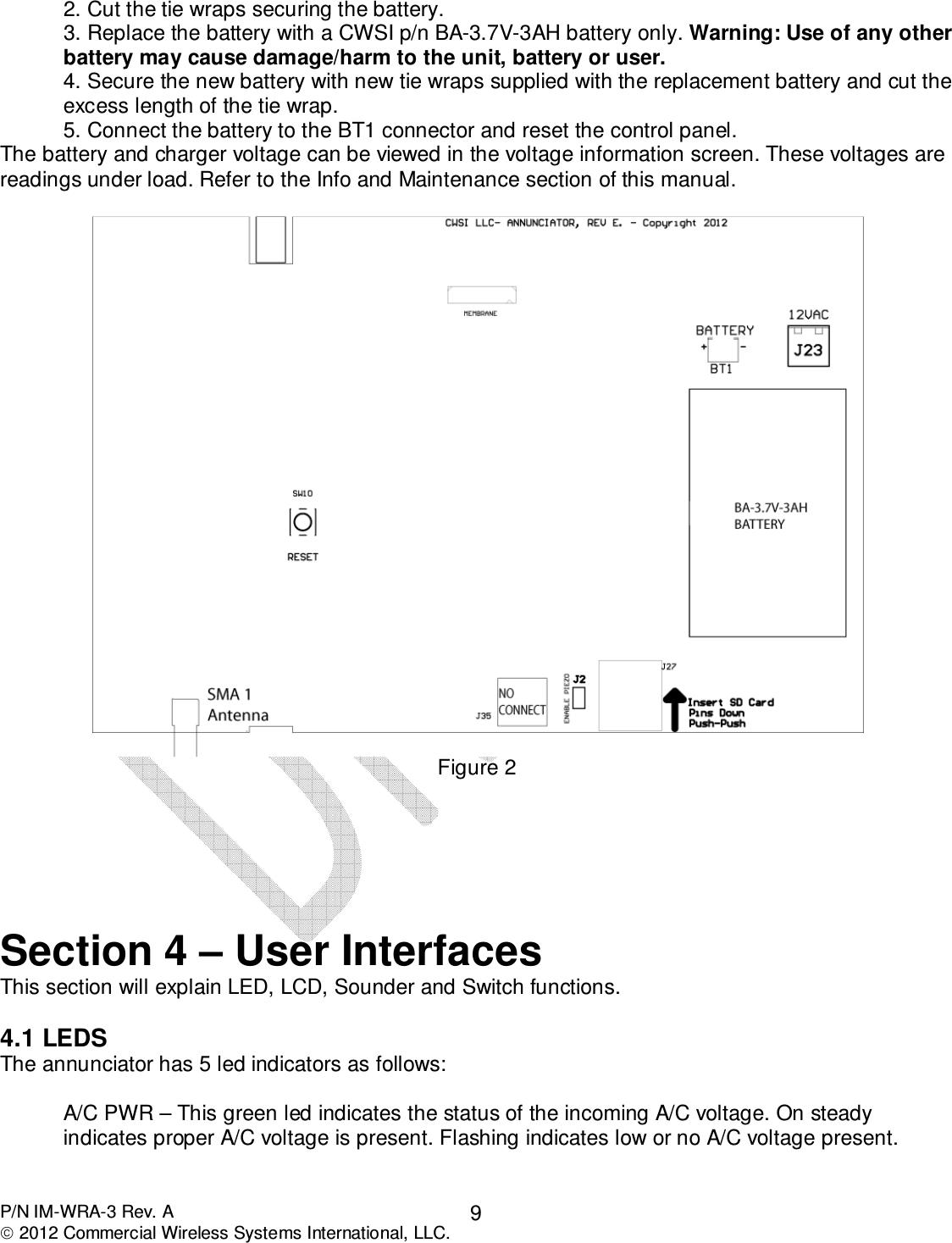
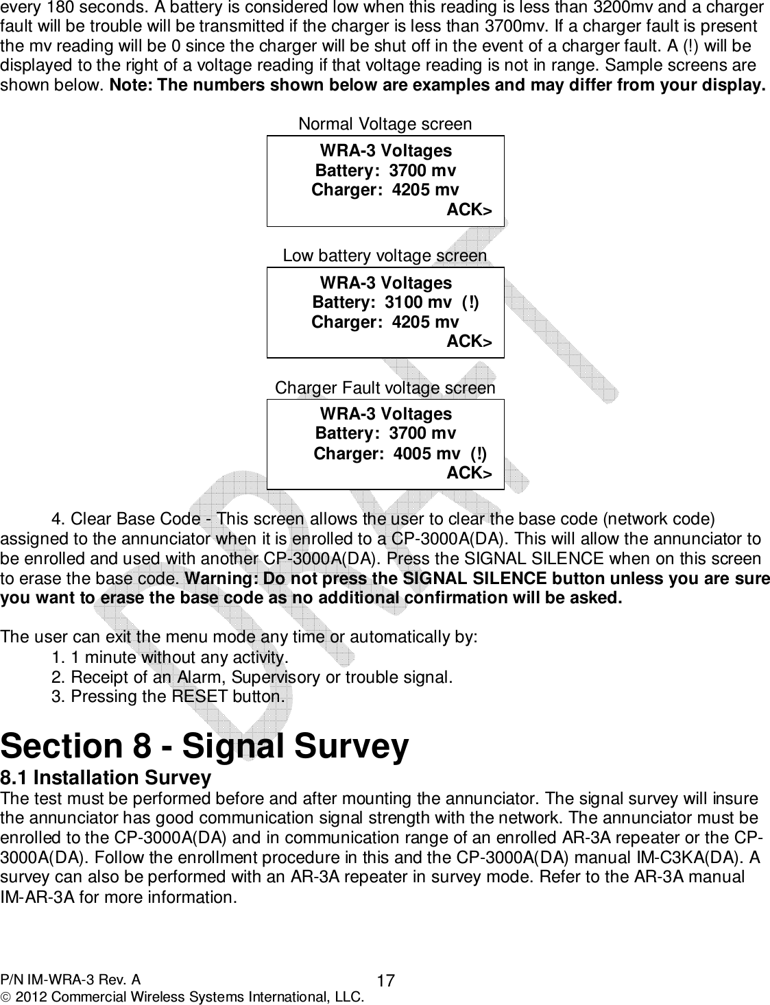
![P/N IM-WRA-3 Rev. A 2012 Commercial Wireless Systems International, LLC. 4 Introduction This manual is intended for persons involved with the installation, maintenance and operation of the WRA-3 wireless remote annunciator. It is a comprehensive guide that provides details on product operation and should be kept for future reference. This manual consists of separate sections. Each section contains information in a manner as to be clear as possible. It is designed to provide all the information necessary to install, program and operate the equipment. Read and understand this manual prior to installing or operating the equipment. It is imperative that the installer understand the requirements of the Authority Having Jurisdiction (AHJ) and be familiar with the standards set forth by Underwriters Laboratories, NFPA 72 National Fire Alarm Code, and NFPA 70 National Electrical Code. The model WRA-3 is a wireless remote annunciator manufactured by CWSI. The annunciator was designed and tested to comply with NFPA 72 National Fire Alarm Code and UL 864 standard. FCC Statements FCC Warning Important: Any changes or modifications not expressly approved by the party responsible for compliance could void the user’s authority to operate the equipment. This device complies with part 15 of the FCC Rules. Operation is subject to the following two conditions: (1) This device may not cause harmful interference, and (2) this device must accept any interference received, including interference that may cause undesired operation. FCC Warning – RF Exposure Important: When using this device, a certain separation distance between antenna and nearby persons has to be kept to ensure RF exposure compliance. in order to comply with the RF exposure limits established in the ANSI C95.1 standards, the distance between the antennas and the user should not be less than [20cm].](https://usermanual.wiki/Simplex-Time-Recorder/WRA3/User-Guide-2056767-Page-4.png)