Simrad Hs50 Users Manual Instruction Manual, GB
SIMRAD HS50 to the manual 6b1e472b-7c2d-4ef0-a0dd-8ca9cb0bdfa3
2015-02-02
: Simrad Simrad-Simrad-Hs50-Users-Manual-491967 simrad-simrad-hs50-users-manual-491967 simrad pdf
Open the PDF directly: View PDF ![]() .
.
Page Count: 63
INSTRUCTION MANUA
L
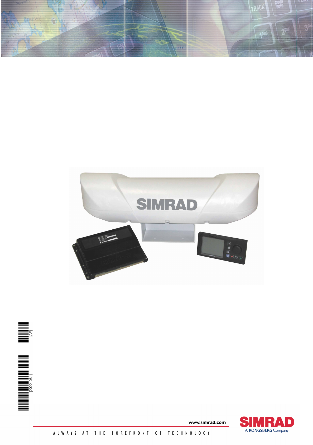
Simrad HS50
Heading Sensor

Note!
Simrad AS makes every effort to ensure that the information contained within this
document is correct. However, our equipment is continuously being improved and
updated, so we cannot assume liability for any errors which may occur.
Warning!
The equipment to which this manual applies must only be used for the purpose for which
it was designed. Improper use or maintenance may cause damage to the equipment or
injury to personnel. The user must be familiar with the contents of the appropriate
manuals before attempting to operate or work on the equipment.
Simrad AS disclaims any responsibility for damage or injury caused by improper
installation, use or maintenance of the equipment.
Copyright
© 2002 Simrad AS
The information contained within this document remains the sole property of Simrad AS.
No part of this document may be copied or reproduced in any form or by any means, and
the information contained within is not to be communicated to a third party, without the
prior written consent of Simrad AS.

INSTRUCTION MANUAL
20221081 / F i
Instruction Manual
HS50 Heading Sensor
This manual is intended as a reference guide for installing,
operating and maintaining Simrad HS50 Heading Sensor.
Simrad HS50 Heading Sensor
ii 20221081 / F
Document revisions
Rev Date Written by Checked by Approved by
A 12.06.02 FOS/
B 26.09.02
C 06.11.02
D 02.04.03 FOS/
E 06.11.03 FOS/
F 07.01.04
Document history
Rev. A Original issue.
Rev. B The manual updated and rewritten.
Rev. C Cable pair numbers for Sensor unit corrected (page 13). Optional documentation for
additional languages added.
Rev. D Updated to correspond with PU sw version 2.02.03 and DU sw version 1.02.
Rev. E Updated to correspond with PU sw version 2.02.04, DU sw version 1.03. and SU sw version
1.02 . Dim. drawing for Sensor unit updated to show mounting direction.
Rev.F Corrected part number for HS50 Display unit mounting bracket (page 16).
To assist us in making improvements to this manual, we would welcome comments and
constructive criticism. Please send all such - in writing to:
Simrad Egersund AS
Nyåskaien
P.O. Box 55
N-4379 Egersund, Norway
or by e-mail to:
simrad.documentation@simrad.com

INSTRUCTION MANUAL
20221081 / F iii
Contents
1. INTRODUCTION ................................................................1
1.1 HS50 System components............................................. 1
1.2 About this manual ........................................................ 3
1.3 Definitions, abbreviations and acronyms.......................... 3
Definitions .......................................................................3
Abbreviations and acronyms...............................................4
2. TECHNICAL SPECIFICATIONS ...........................................5
2.1 Health, environment and safety ..................................... 5
2.2 Restrictions in guarantee............................................... 5
2.3 Restrictions in use ........................................................ 5
2.4 Performance data......................................................... 6
2.5 Physical dimensions...................................................... 6
Sensor unit ......................................................................6
Display unit .....................................................................6
Processing unit .................................................................7
2.6 Power......................................................................... 7
Processing unit .................................................................7
2.7 Environmental specification ........................................... 7
Sensor unit ......................................................................7
Display unit .....................................................................7
Processing unit .................................................................8
2.8 Cable ......................................................................... 8
Processing unit to sensor unit cable .....................................8
2.9 Interface..................................................................... 8
3. INSTALLATION..................................................................9
3.1 General ...................................................................... 9
3.2 Cable connection.......................................................... 9
3.3 Grounding................................................................... 9
3.4 Sensor unit ................................................................10
Location of the unit ......................................................... 10
Mechanical installation..................................................... 11

Simrad HS50 Heading Sensor
iv 20221081 / F
Cable wiring................................................................... 13
Waterproofing the connectors ........................................... 14
3.5 Display unit ................................................................14
Location of the unit ......................................................... 14
Panel mounting .............................................................. 15
Bracket mounting (option) ............................................... 16
Display unit cable ........................................................... 17
3.6 Processing unit ...........................................................18
Cable connections ........................................................... 19
Connecting to Simrad equipment ...................................... 21
3.7 Software setup procedure.............................................24
Display Adjustments........................................................ 25
Differential corrections..................................................... 26
Data output ................................................................... 27
Ethernet ........................................................................ 28
General ......................................................................... 28
Expert setup .................................................................. 30
4. OPERATING INSTRUCTIONS ...........................................33
4.1 Overview ...................................................................33
4.2 Turning the system ON/OFF..........................................34
4.3 Performance monitoring ...............................................34
Navigation/HDT display ................................................... 36
Navigation/POS display.................................................... 36
Info displays .................................................................. 37
4.4 Alarms.......................................................................39
Invalid Position alarm ...................................................... 40
Invalid Heading alarm ..................................................... 40
Invalid Position and Heading alarm.................................... 40
4.5 Operation...................................................................41
Height aided GPS position ................................................ 41
5. MAINTENANCE ................................................................43
5.1 General .....................................................................43
5.2 Periodic maintenance...................................................43
Sensor unit .................................................................... 43

INSTRUCTION MANUAL
20221081 / F v
Processing unit ............................................................... 44
Display unit ................................................................... 44
Software upgrades.......................................................... 44
5.3 Repairs and modifications.............................................45
Replacing damaged cables ............................................... 45
Replacing damaged units ................................................. 45
5.4 Troubleshooting ..........................................................45
No response................................................................... 46
No valid data.................................................................. 46
No Differential corrections ................................................ 47
Invalid Heading .............................................................. 47
Reduced heading indication .............................................. 48
Simulated data ............................................................... 48
6. FIGURES AND DRAWINGS...............................................49
6.1 Sensor unit, dimensions ...............................................50
6.2 Sensor unit bracket, dimensions....................................51
6.3 Sensor unit pedestal, dimensions ..................................52
6.4 Processing unit, dimensions..........................................53
6.5 Display unit, dimensions ..............................................54
7. PARTS LIST .....................................................................55
7.1 Standard delivery........................................................55
7.2 Optional equipment .....................................................55
7.3 Documentation ...........................................................55

Simrad HS50 Heading Sensor
vi 20221081 / F
THIS PAGE INTENTIALLY LEFT
BLANK
INTRODUCTION
20221081 / F 1
1. INTRODUCTION
1.1 HS50 System components
Simrad HS50 is a GPS compass that provides true heading
output with position, velocity and rate of turn information in
addition. This product replaces several vessel instruments with
one compact navigation package: gyrocompass, GPS system,
speed log and Rate Of Turn (ROT) indicator.
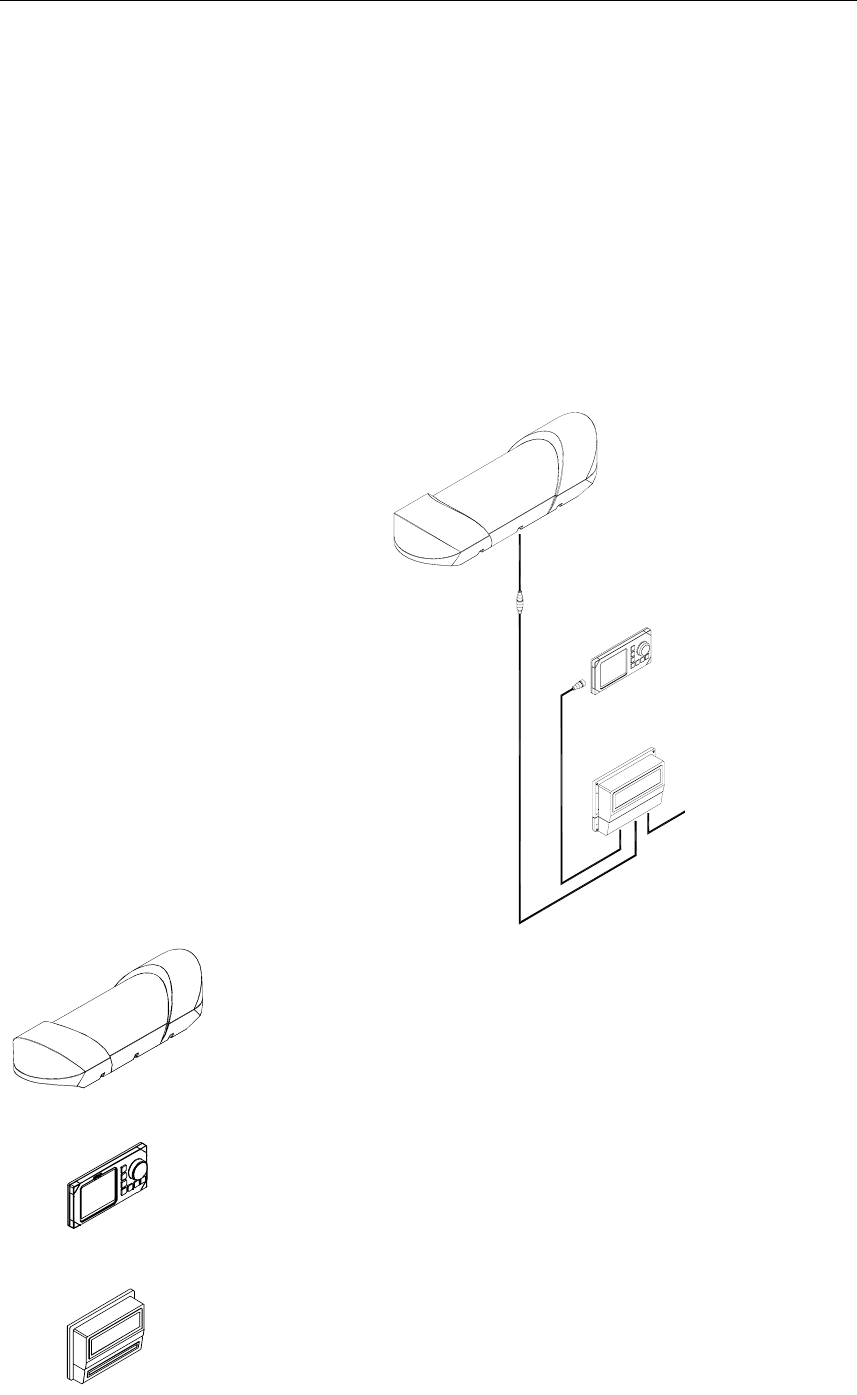
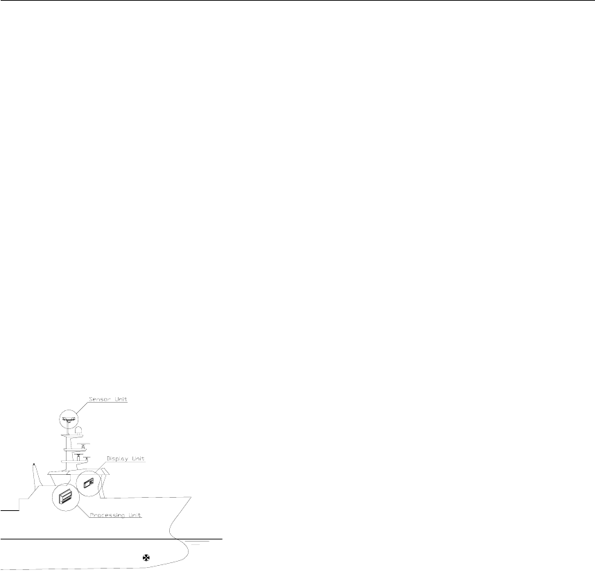
The HS50 comprises the following units:
The Sensor unit contains two GPS sensors, electronic board
with I/O and an inertial rate element.
The Sensor unit is to be mounted in the vessel’s mast or flat on
a roof or deck.
The Display unit contains an LCD for navigation information,
mainboard with CPU, flash, power and I/O, and buttons for
setup and operation of the HS50 system.
The Processing unit contains the mainboard with CPU, flash,
power, I/O and a terminal list.
SENSOR UNIT
DISPLAY UNIT
PROCESSING
UNIT
1m
30m
POWER INPUT
15m

Simrad HS50 Heading Sensor
2 20221081 / F
High-precision heading is derived from the fixed-distance dual
GPS antenna arrangement in the Sensor unit, using carrier phase
data to generate heading information independent of latitude and
vessel dynamics. GPS position and speed are calculated from
both antennas, which give redundant position and velocity
sources in this product. DGPS signals may be input to the HS50
to improve position and velocity accuracy, but has no impact on
the heading accuracy. Refer Performance data, page 6.
The inertial rate element provides yaw/ROT information. In case
of short GPS outages, the inertial sensor automatically takes
over as the prime source for heading determination until the
GPS comes back on line. Working together seamlessly, the
inertial and GPS elements of the system insure accurate,
continuous and robust heading information.
The Processing unit includes configurable output serial lines
(three RS-232 and three RS-422) and Ethernet connections
making it easy to distribute HS50 data to multiple users on
board the vessel.
The HS50 requires no scheduled maintenance or re-calibration.
The system offers flexible configuration of the output variables
and interface setup, depending on the vessel and application. It
is easy to operate, install and align.
The HS50 system has the following features:
• True heading anywhere on earth
• Replaces several instruments with one robust, integrated
product
• Heading available in periods of GPS drop-outs
• 20 Hz update rate on heading and rate of turn measurements
• 80°/sec follow-up rate
• Three RS-232 and three RS-422 configurable output serial
lines
• Output data on Ethernet
• Only one cable (no coax) between the mast unit and the
Processing unit on the bridge

INTRODUCTION
20221081 / F 3
1.2 About this manual
This manual is intended as a reference guide for operating,
installing and maintaining the HS50 Heading Sensor. Please
take time to read this manual to get thorough understanding of
the operation and system components.
In this manual the following notations are used:
Caution! Used to make the user aware of procedures and operational
practice which, if not followed, may result in degraded
performance or damage to the equipment.
Note! Used to draw the user's attention to special features or behavior
of the equipment.
1.3 Definitions, abbreviations and acronyms
Definitions
Alignment The process of adjusting the current internal navigation frame
(sensor-frame) in the instrument to the true vessel body frame.
Heading The direction of the main axis (bow direction) of the vessel.
This is opposed to course, which is the direction of the vessel
motion.
Yaw A rotation about the vertical axis and is positive when turning
eastward when the vehicle cruises in north direction. Normally
yaw means the dynamic yaw motion.

Simrad HS50 Heading Sensor
4 20221081 / F
Abbreviations and acronyms
CEP Circular Error Probability
COG Course Over Ground
DGPS Differential GPS
DU HS50 Display Unit
EPE Estimated Position Error
GPS Global Positioning System
GSA A standard NMEA message including GPS satellite ID
numbers, PDOP, HDOP and VDOP
HDOP Horizontal Dilution Of Precision
HGT GPS Antenna Height above the WGS-84 ellipsoid
IEC International Electrotechnical Commission
IMO International Maritime Organization
I/O Input/Output
NMEA National Marine Electronics Association. NMEA 0183 is a
standard for interchange of information between navigation
equipment
PDOP Positional Dilution Of Precision. This is the sum of the VDOP
and HDOP figure
PSXN20 A proprietary NMEA message including position, height and
heading quality information
PU HS50 Processing Unit
RFI Radio Frequency Interference
RF Radio Frequency
RMS Root Mean Square
ROT Rate of Turn
RRE Range Residual Error, a proprietary format
RTCM Radio Technical Commission of Maritime Services
SOG Speed over Ground
SSB Single Side Band
UTC Universal Time Co-ordinate. This is the official time in the
world and has replaced GMT (Greenwich Mean Time) as the
official time
VDOP Vertical Dilution Of Precision
VHF Very High Frequency
WGS-84 World Geodetic System of 1984

TECHNICAL SPECIFICATIONS
20221081 / F 5
2. TECHNICAL SPECIFICATIONS
2.1 Health, environment and safety
Operation or troubleshooting of HS50 equipment will not imply
any risk for high voltages, explosions or exposure to gas. The
HS50 is type-approved according to IEC 950/EN60950
standards regarding product safety (low voltage), and IEC
945/EN60945 standards on electromagnetic compatibility
(immunity/radiation) and vibration.
2.2 Restrictions in guarantee
The liability of the manufacturer is limited to repair of the HS50
only, and excludes consequential damages such as customer's
loss of profit or damage to other systems traceable back to HS50
malfunction. The warranty does not cover malfunctions of the
HS50 resulting from the following conditions:
a) The customer has opened the Sensor unit
b) Over-voltage or incorrect power connection
c) The equipment has been exposed to extreme chock and
vibrations
2.3 Restrictions in use
Simrad HS50 is designed for use on board marine surface
operated vessels with roll and pitch motions up to ±30°.
The HS50 function is based on GPS signals and requires free
sight to the sky, minimum 4 visible satellites, PDOP value less
than 6 and otherwise normal conditions to operate.

Simrad HS50 Heading Sensor
6 20221081 / F
2.4 Performance data
Heading accuracy, static:...............................................0.3° RMS
Heading accuracy, dynamic:..........................................0.5° RMS
Heading resolution:............................................................... 0.01°
Heading operational measurement range: .Roll/pitch within ±30°
Rate of turn accuracy:................................................. 0.5º/s + 5%
Position accuracy:...................................................5 m 95% CEP
Velocity accuracy: ............................................ 0.1 m/s 95% CEP
Follow-up rate:...................................................................80°/sec
The performance figures are valid with a minimum of 4 visible
satellites, HDOP less than 4, PDOP value less than 6, high
quality DGPS corrections * and otherwise normal conditions.
Excessive multipath, GPS signal obstructions or interference
may reduce the performance.
The HS50 Sensor unit includes two 12 channels GPS receivers.
* Has no impact on heading accuracy.
2.5 Physical dimensions
Sensor unit
Width ................................................................850 mm (33.5 in.)
Height: ................................................................205 mm (8.1 in.)
Depth: ...............................................................262 mm (10.3 in.)
Weight: ................................................................. 8 kg (17.6 lbs.)
Color: ...................................................................................White
Dimensional drawing........................................................Page 50
Display unit
Width: .................................................................220 mm (8.7 in.)
Height: ................................................................110 mm (4.3 in.)
Depth: ...................................................................39 mm (1.5 in.)
Weight: ................................................................ 0.5 kg (1.1 lbs.)
Color: ................................................................................... Black
Dimensional drawing........................................................Page 54

TECHNICAL SPECIFICATIONS
20221081 / F 7
Processing unit
Width: ...............................................................287 mm (11.3 in.)
Height: ...................................................................203 mm (8 in.)
Depth: ...................................................................60 mm (2.4 in.)
Weight: ................................................................ 1.3 kg (2.9 lbs.)
Color: ................................................................................... Black
Dimensional drawing........................................................Page 53
2.6 Power
Processing unit
Voltage:.................................................................. 10 to 36 V DC
Power consumption: .............................................................15 W
2.7 Environmental specification
Sensor unit
Enclosure material, sensor housing: .........................Polyethylene
Enclosure material bracket: ..........................Anodized aluminum
Enclosure protection:............................................................. IP65
Operating temperature range: ........... -30 to +55ºC (-22 to 131°F)
Operating humidity (max.): ................................................. 100%
Storage temperature range:............... -30 to +70ºC (-22 to 158°F)
Storage humidity (max.):..................................................... 100%
Safe distance to compass: ........................................ 0.2 m (0.7 ft)
Display unit
Enclosure protection:.............. IP-56 from front, IP-43 from back
Operating temperature range: ................0 to +55ºC (32 to 131°F)
Storage temperature range:............... -30 to +80ºC (-22 to 176°F)
Safe distance to compass: ..................................... 0.35 m (1.1 ft.)

Simrad HS50 Heading Sensor
8 20221081 / F
Processing unit
Enclosure material: .......................................Anodized aluminum
Enclosure protection:............................................................. IP44
Operating temperature range: ................0 to +55ºC (32 to 131°F)
Storage temperature range:................. -20 to +60ºC (-4 to 140°F)
Safe distance to compass: ........................................ 0.2 m (0.7 ft)
2.8 Cable
Processing unit to sensor unit cable
Type: ......................................................2x2x0.5 mm2 with shield
Maximum length:................................................... 100 m (328 ft)
Diameter: ..............................................................10 mm (0.4 in.)
Flame retardation:.....................................................IEC 332-3/A
2.9 Interface
Configuration:....... Display unit connected to the Processing unit
Data outputs:........................................Three RS-232 serial lines,
Three RS-422 serial lines,
Ethernet UDP/IP
Data inputs:.................... One RS-232 and one RS-422 serial line
DGPS corrections: ..... RTCM 104 version 2.2 and SAPOS® EPS
Baud rate:...........................................................Max. 38.4 kBaud
HDT, ROT, GGA and GLL data update rates:.......... Up to 20 Hz
HDT, ROT, GGA and GLL data delay:...............Less than 50 ms
ZDA and VTG data update rate:....................................Max 1 Hz
VTG data delay:......................................................... Max 1.5 sec
ZDA data delay:..................................................................... 1 ms
Data output formats:
• NMEA 0183 ZDA, GGA, GLL, VTG, HDT, ROT, GSA,
GRS and proprietary messages PSXN,20. The PSXN,20
message include position, height and heading quality
information
• RD Instrument ADCP proprietary NMEA format, "PRDID".
• Radar clock data
INSTALLATION
20221081 / F 9
3. INSTALLATION
3.1 General
The following parts are supplied with a standard HS50 system:
− Sensor unit with 1 meter cable w/connector and 4
fastening bolts
− Display unit with 15 meters cable to the Processing
unit and flush mounting kit
− Processing unit including 4 fastening screws
− 30 meters cable to be used between Sensor unit and
Processing unit
− Documentation
Caution!
The Sensor unit has to be mounted in a way that
avoids blocking of the GPS signal.
The Processing and Display Unit can be
mounted on the bridge or in the instrument
room.
No units should be exposed to heavy vibration,
transformers or similar.
3.2 Cable connection
Use only shielded cables for the installation. This includes
power input and signal cables. The cables should be of 0.5 mm2
(AWG20) twisted pairs.
The cable to the Display unit and other cables (NMEA
input/output, Ethernet) should not be run in parallel with other
cables carrying RF or high current, such as VHF and SSB
transmitters, battery charges/generators and winches.
3.3 Grounding
All units in the HS50 system use the Processing unit as a
common ground/shield connection. The Processing unit should
therefore have a proper ground connection to the hull/bonding
system.
Simrad HS50 Heading Sensor
10 20221081 / F
3.4 Sensor unit
Location of the unit
The Sensor unit is the most important part of the HS50 system,
and great care should be taken when deciding the mounting
location.
The space above the Sensor unit has to be free of obstructions of
any kind. A GPS compass is more sensitive for blocking and
reflections (multipath) of GPS signals than GPS sensors that are
only used for calculating position. This since HS50 also utilizes
carrier phase measurements for heading determination, and both
GPS antennas need to see at least two common satellites at the
same time.
The unit should be protected from direct illumination of radar
beams and other transmitting antennas such as Inmarsat
antennas.
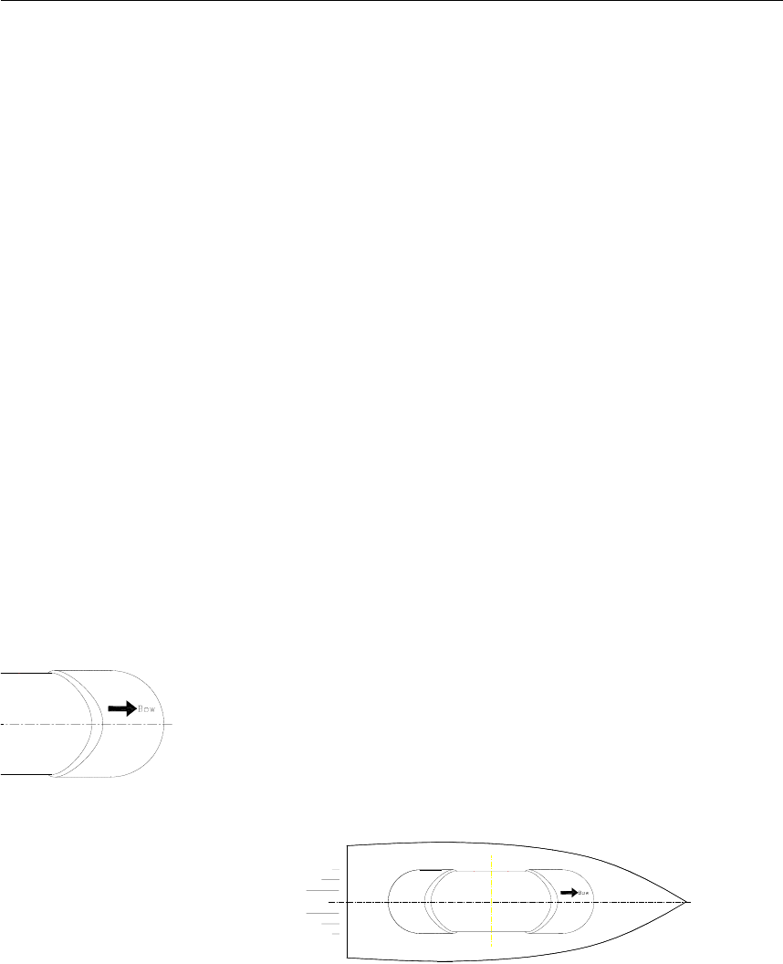
The Sensor unit has to be mounted horizontally in the mast or
directly on deck, with 5° maximum allowed deviation angle
from the horizontal plane. If mounted in the mast, the distance
from the unit to the nearest deck should be as large as possible
to reduce problem due to the multipath effect.
The unit should also be mounted parallel to the vessel’s
centerline with the bow arrow pointing forward. The heading
offset feature will however compensate for a heading offset
caused by the orientation of the Sensor unit. An eventual offset
correction is performed after the calibration as described in
Software setup procedure, Heading offset, page 31.
INSTALLATION
20221081 / F 11
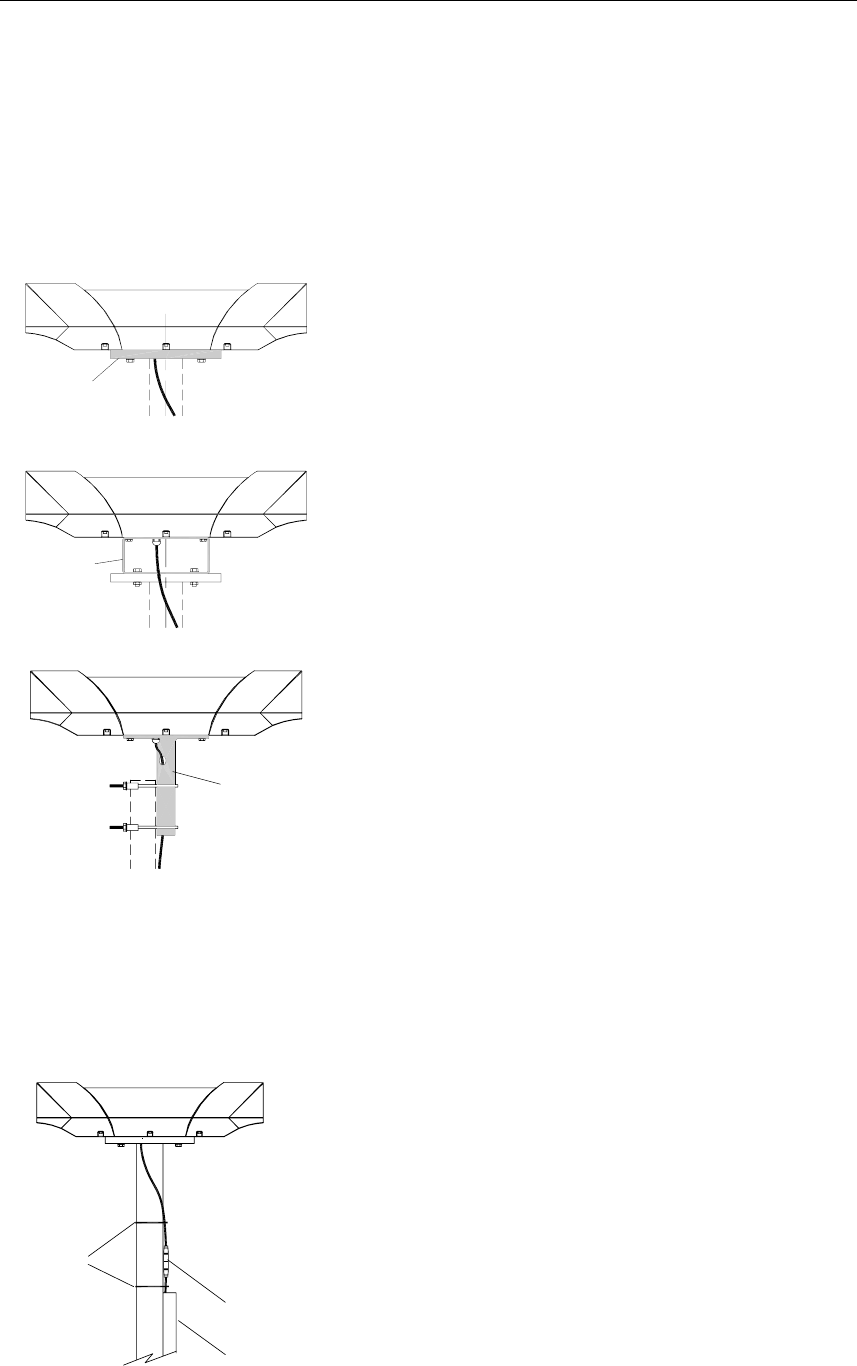
Mechanical installation
The Sensor unit may be mounted in the mast or directly on the
deck.
The dimensional drawing for the Sensor unit on page 50 shows
dimensions and internal distance for the mounting holes and the
cable outlet.
Holder
If necessary, a user-made holder may be used as
shown on the figure when installing the unit.
Bracket
Pedestal
A mounting bracket (part no. 20213039) or a
mounting pedestal (part no 20213021) can be
delivered from Simrad by request. Dimensions for
these optional mounting devices are shown on page
51 and page 52.
Refer Bracket mounting (option), page 12, and
Pedestal mounting (option), page 13.
Caution! Independent on which fastening method that is used, the
Sensor unit should not differ more than ±5° from the vessel’s
horizontal plane and the alongships axis. If the mounting is
not within this tolerance, the heading accuracy will be
degraded.
Connectors with
Cable duct
Cable ties
self-bonding tape
Connect the cable from the Processing unit to
the cable from the Sensor unit.
Caution!
The connector junction must be sealed with
self-bonding tape for waterproofing. After
coiling, make bonding by hard pressure.
Use the required number of cable ties to fasten
the cable to the mast.
Simrad HS50 Heading Sensor
12 20221081 / F
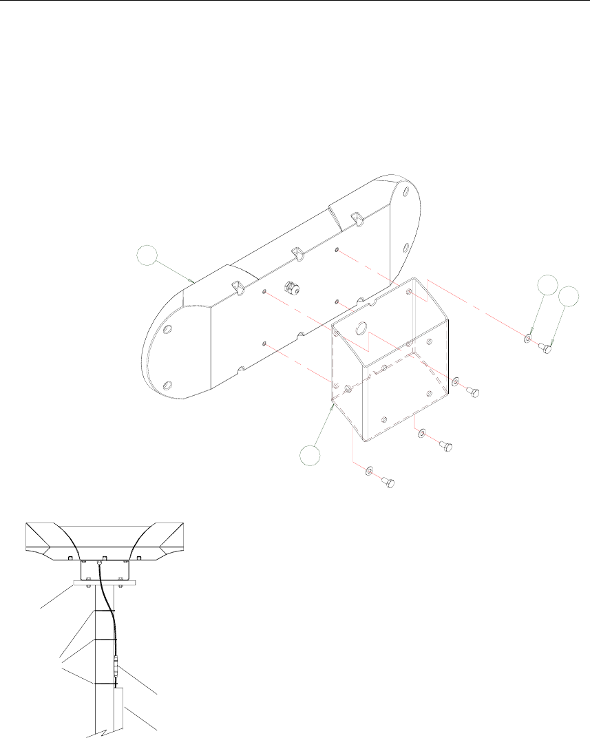
Bracket mounting (option)
An optional mounting bracket (part no. 20213039) can be
delivered from Simrad by request.
Assemble the mounting bracket to the Sensor unit with the four
screws with washers as shown in the figure below.
4
10
11
12
Cable ties
Holder
self-bonding tape
Cable duct
Connector with
Connect the cable from the Processing unit to
the cable as described in page 11.
INSTALLATION
20221081 / F 13
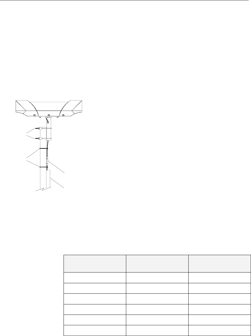
Pedestal mounting (option)
An optional mounting pedestal (part no. 20213021) can be
delivered from Simrad by request. This pedestal is designed for
2-inch mast mounting.
Attach the pedestal to the Sensor unit with the four screws and
washers similar to the bracket mounting option described on
page 12.
self-bonding tape
Connector with
Cable duct
Cable ties
Pipe clamps
1 Lift the Sensor unit in the preferred direction
on the mast. Use two pipe clamps with
preferred size for mounting the Sensor unit
pedestal to the mast top.
2 Ensure that the Sensor unit is mounted in
such a way that torsion movement relative to
the mast is kept at an absolute minimum.
All nuts should be secured with washers or by
self-locking nuts.
Connect the cable from the Processing unit to the cable as
described in page 11.
Cable wiring
The wiring for the Sensor unit cable in the Processing unit
terminals is as follows:
Cable Wire No. Signal Description Processing Unit
Connector P201
Label
Screen Cable shield GND
4 Transmit COMM+
3 Receive COMM-
2 +24 VDC PWR+
1 Power ground PWR-
Simrad HS50 Heading Sensor
14 20221081 / F
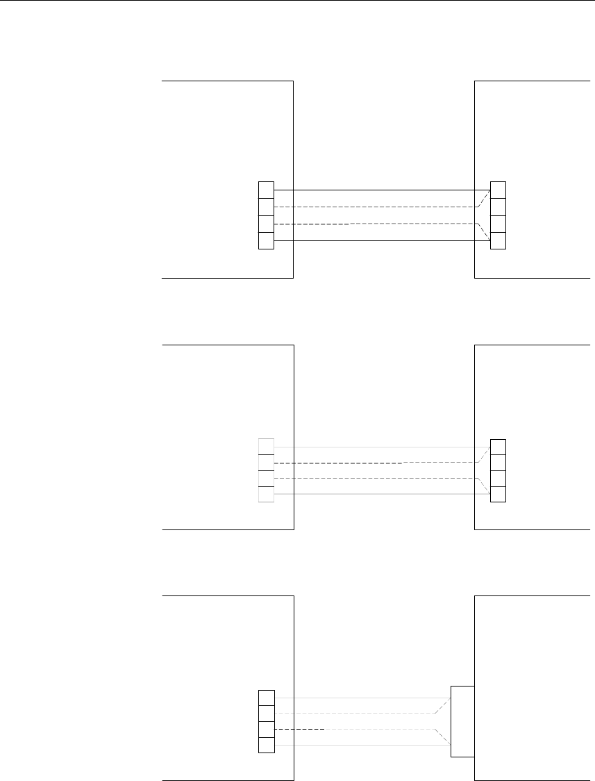
If the Sensor unit connector needs to be reconnected to the
cable, the wiring for the cable within the Sensor unit connector
is as follows:
Sensor Unit
Connector Cable Wire No. Signal Description
Pin no.
Connector housing Screen Shield
2 4 Transmit
4 3 Receive
3 2 +24 VDC
1
2
4
3
FRONT VIEW
1 1 Power ground
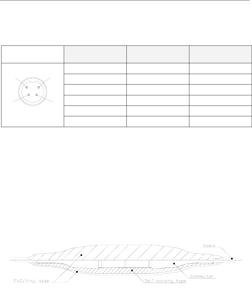
Waterproofing the connectors
The Sensor unit connector junction has to be sealed with self-
bonding tape and PVC/Vinyl tape for waterproofing.
1 Coil the self-bounding tape from one cable end to the
other. Use at least two layers with tape. After coiling,
make a bonding by pressure of fingers.
2 Coil at least two layers of PVC/Vinyl tape without
stretching as shown in the figure below. After coiling,
make a bonding by pressure of fingers.
3.5 Display unit
Location of the unit
Avoid mounting the Display unit where it is easily exposed to
sunlight, as this will shorten the lifetime of the display. If this is
not possible, make sure the unit is always covered with the
white protection cover when not used.
The unit is designed for installation in an indoor environment
and for operation within the temperature range. The best
location is typically in the instrument room or on the bridge
mounted close to the Processing unit.
INSTALLATION
20221081 / F 15
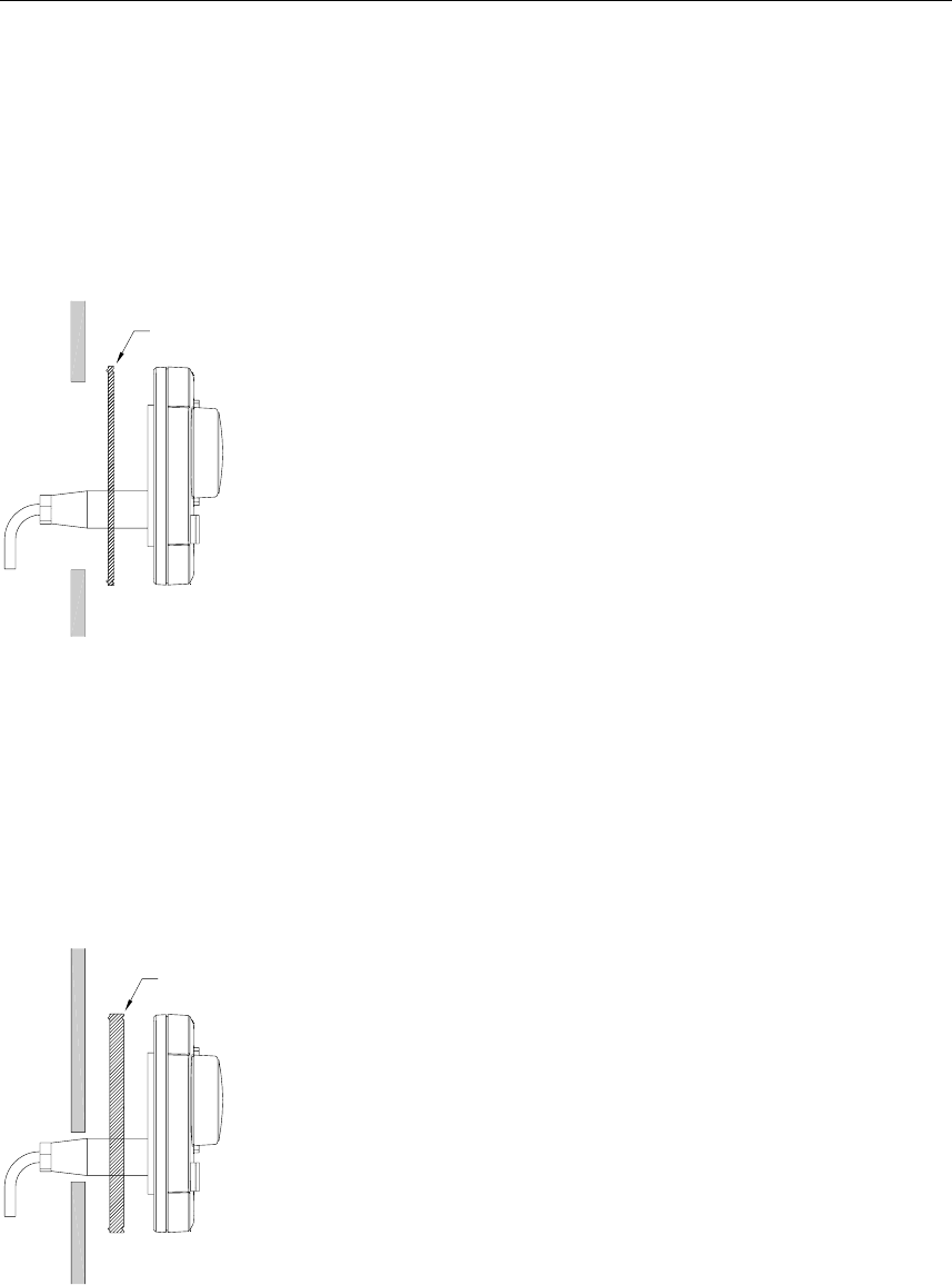
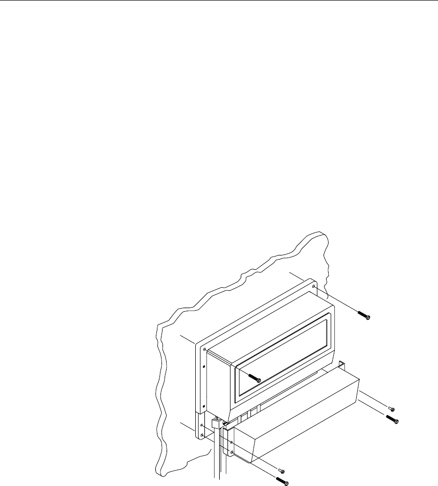
Panel mounting
Two mounting methods may be used when panel mounting the
HS50 Display unit.
A drilling template, part no. 22084883, is supplied with the
HS50 documentation. Use this template when making panel cut-
out and drilling holes.
Gasket
1 Remove the front panel corners.
2 Drill the mounting holes and make panel cut-out according
to supplied template.
3 Use the supplied gasket (part no. 22084693) between the
panel and the unit.
4 Fasten the Display unit to the panel with the supplied 19
mm screws.
5 Apply the front panel corners.
6 Connect the Processing unit cable to the Display unit
connector.
Caution! Do not over-tighten the mounting screws.
Alternative panel mounting
This way of mounting is simpler, but will lift the unit from the
panel surface. When installed adjacent to Simrad MarineLine
equipment there will be a 5.5 mm (0,22") difference in height
between the Display unit and other equipment.
Gasket
1 Remove the front panel corners.
2 Use the template and drill hole(s) only for the connectors.
3 Place the 7.5 mm gasket (part no. 22086029) between
panel and unit, correctly oriented (see marking on gasket).
4 Fasten the Display unit to the panel with the supplied 19
mm screws.
5 Apply the front panel corners.
6 Connect the Processing unit cable to the Display unit
connector.
Simrad HS50 Heading Sensor
16 20221081 / F
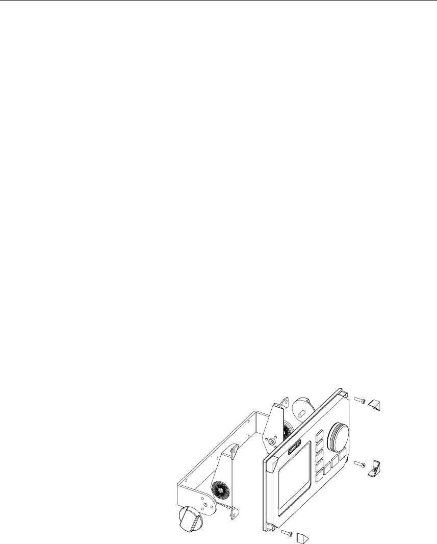
Bracket mounting (option)
An optional bracket, part no. 22084941, may be ordered from
Simrad.
Note! When the Display unit is bracket-mounted, it is not
weatherproof from the back due to a breathing hole in the back
cabinet. When bracket-mounted, the exposed parts of the plugs
should be protected against salt corrosion.
1 Locate the cradle on the mounting site and mark the 4
holes for the screws on the mounting surface.
2 Drill the 4 holes and screw the cradle to the mounting
surface.
3 Remove the front panel corners, and use the supplied
screws to fasten the Display unit to the left and right
brackets.
4 Apply the front panel corners.
5 Use the two locking knobs to assemble the cradle with the
left and right brackets and adjust the Display unit for the
best viewing angle.
6 Connect the cable from the Processing unit to the Display
unit connector.
INSTALLATION
20221081 / F 17
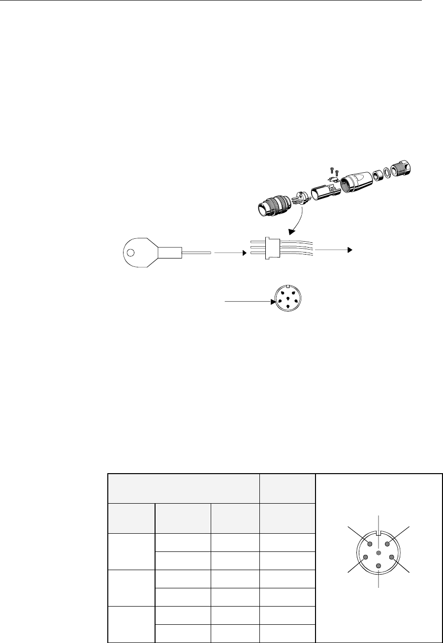
Display unit cable
The 15 m cable to the Processing unit has connector only at the
Display unit end. Optional extensions cable (10 m) is available
and has a male and a female connector.
The connector is of crimp type. It can be easily disassembled, if
desired for ease of installation. The extracting tool (p.no.
44161792) may be ordered from Simrad.
HOW TO REMOVE PINS:
Extraction tool
Pull the wire
Insert tool in slot
See the table below for pin configuration and color code for this
cable. DO NOT MIX THE PINS AND THE CABLE COLORS!
Note! Apply a thin layer of pure Vaseline on the connector threads
and make sure the connectors are properly secured to the
receptacle by the coupling ring. The connectors are weather
proof according to IP56, when properly installed. The plug must
be fitted with the plastic cap to keep the connector free of dirt
and moisture. A separate screw cap for the Display unit comes
as part of the installation kit.
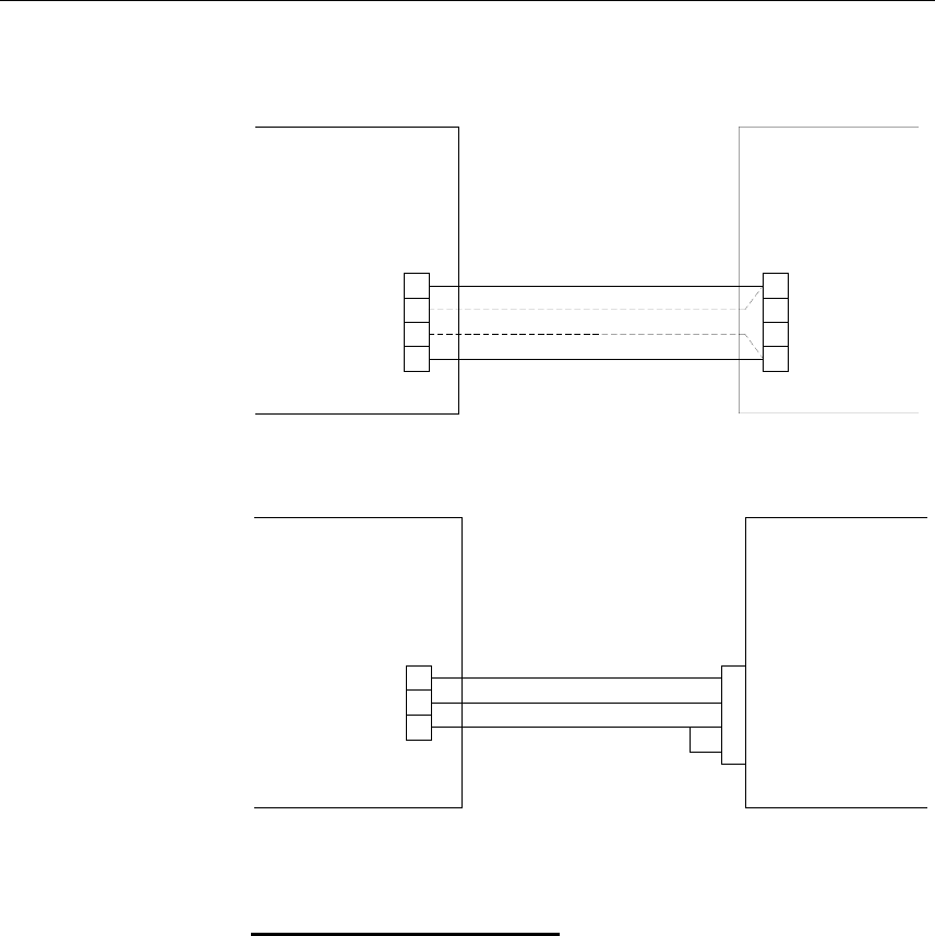
Display Unit Cable Processing
Unit
Cable
pairs
Color
code
Connect
or pin
Terminal
pin
1st pair Pink 5 PWR
Grey 4 GND
2nd pair Brown 1 Bus–
White 2 Bus+
3rd pair Yellow 3 POWC
Green 6 ALARM
5
42
1
6
FRONT VIEW
3
Note! For installations that require special cable length, contact your
Simrad distributor for information.
Simrad HS50 Heading Sensor
18 20221081 / F
3.6 Processing unit
The Processing unit is not waterproof and should be mounted
vertically in a dry place. Reserve sufficient space below the unit
to allow insertion for cable connections.
It is recommended that ventilation or air conditioning is
provided in order to keep the ambient operating temperature
below +55ºC (+130ºF). The best location is typically in the
instrument room or on the bridge.
Dimensions for the Processing unit are shown on page 53.
Use the supplied mounting screws for fastening the Processing
unit as shown on the figure below.
INSTALLATION
20221081 / F 19
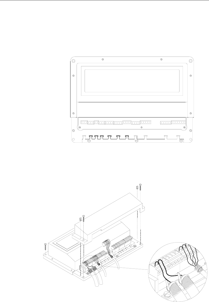
Cable connections
Proceed as follows to connect the cables to the Processing unit:
1 Remove the bottom cover (terminal cover) to get access to
the plug-in terminals.
2 Strip 1 cm (0.4") of the cable's insulation and pull the
screen backward to cover the insulation. Position the
straps as shown in the figure below and tighten well to
make sure the screen has good contact.
3 Provide sufficient wire length so that the plug-in terminals
can be easily connected/disconnected.
4 Pull out each terminal before connecting the wires.
Remove all stands before putting on the terminal cover.
Simrad HS50 Heading Sensor
20 20221081 / F
The pinout for each terminal is as follows:
ALARM GREEN
POWC YELLOW
P200 DISPLAY GND GREY
UNIT PWR PINK
BUS+ WHITE
BUS- BROWN
GND SHIELD
COMM + 4
P201 SENSOR COMM - 3
UNIT PWR+ 2
PWR- 1
J60 Ethernet RJ45
P80 NOT USED
232 OUT
P202 DATA 422- OUT
OUT 1 422+ OUT
GND_A
232 OUT
P203 DATA 422- OUT
OUT 1 422+ OUT
GND_B
232 OUT
P204 DATA 422- OUT
OUT 2 422+ OUT
GND_C
422+ IN
P205 DIFF 422- IN
INPUT
P206 DIFF INPUT 232 IN
GND_D
NOT
P207 USED
AD10_C
P208 RADAR AD10_D
AD10_GND
SHIELD
P300 POWER PWR_+
PWR_GND
INSTALLATION
20221081 / F 21
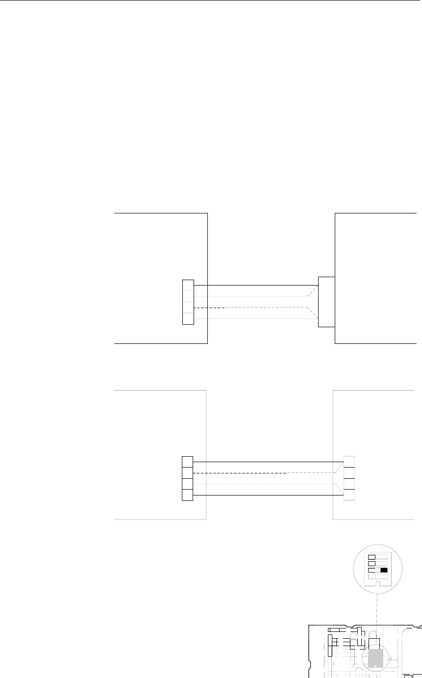
Connecting to Simrad equipment
The figures on the following pages show how HS50 is
connected to Simrad equipment.
All equipment using NMEA signal is connected to 232 OUT
and GND, alternatively to 422– OUT and 422+ OUT on P202,
P203 or P204. After the equipment is connected to HS50, the
data output line has to be configured as described in Data
output, page 27.
Connection to Simrad Radar is done from P208.
AP9MK3 Autopilot
1
2
HS50
PROCESSING UNIT
AP9 MK3
P204 J3
CONTROL UNIT
or
P203
P202,
232 OUT
422+ OUT
GND
422- OUT
RGC Signal Interface unit
PROCESSING UNIT
HS50
SIGN. INTERFACE
RGC
UNIT
NMEA IN -
NMEA IN +
1
2
NMEA IN
P204
or
P203
P202,
232 OUT
422+ OUT
422- OUT
GND
TB3
Note! DIP Switch SW1-2 on the Signal
Interface PCB has to be set to NMEA
according to the figure.
RGC SIGNAL INTER
ROBERTSON TRITE
+
SW1
VR4
1234
Simrad HS50 Heading Sensor
22 20221081 / F
J50/J300X Junction unit
PROCESSING UNIT
HS50
JUNCTION
J50 / J300X
UNIT
RX2+
RX2-
422- OUT
422+ OUT
232 OUT
GND
or
P204
P202,
P203
TB8
NI300X
PROCESSING UNIT
HS50 NI300
UNIT
JUNCTION
422- OUT
422+ OUT
232 OUT
GND
or
P204
P202,
P203
A RX+
B RX-
IS15 Instruments
PROCESSING UNIT
HS50
2
1
J4
IS15
422- OUT
422+ OUT
232 OUT
GND
or
P204
P202,
P203
NMEA
INSTALLATION
20221081 / F 23
RGC12 Gyro Compass
PROCESSING UNIT
HS50
P203
P204
or
P202,
232 OUT
422+ OUT
422- OUT
GND
RGC12
TERMINAL BOARD
GRXH
GRXL
TB7
Simrad RA40/RA50 Radar
PROCESSING UNIT
P208
HS50
AD10_D
AD10_GND
AD10_C
RADAR
GYRCK-
GYRCK+
GYRCK+
GYRCK-
26
27
9
10
Note! Requires the optional 36-pins connector 72099 for the Radar.
Software set-up in Radar
1 Go to menu:
MENU → SETUP → CUSTOM → PRESET1
2 Change Input from NMEA to 10 BIT
3 Change Head from TRUE to MAGNETIC
Simrad HS50 Heading Sensor
24 20221081 / F
3.7 Software setup procedure
This chapter describes a number of installation settings that
must be performed as part of the installation of the HS50.
Failure to correctly set the values in the installation settings may
prohibit the product from functioning properly.
Before attempting to turn on the HS50 and perform an
installation setup, the hardware and electrical installation must
be completed in accordance with the installation instructions.
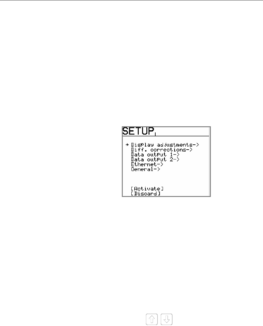
The SETUP menu is entered on the Display unit by pressing and
holding the SETUP button for 5 seconds.
The settings are grouped into the following functional
categories:
• Display adjustments
• Diff. corrections
• Data output 1
• Data output 2
• Ethernet
• General
• (Expert Setup, refer page 30)
Use the arrow buttons to select category, and the
rotary knob to enter a category’s submenu.
The arrow buttons are also used to return from a submenu to the
SETUP menu.
Note! Activate and Discard selection together with the rotary knob is
used to exit the SETUP menu: changes are accepted by using
Activate, and all changes are erased when selecting Discard.
INSTALLATION
20221081 / F 25
Example:
The following example shows how to change the ROT Max
value in the Display adjustment submenu using the keys and
the rotary knob:
1 Press the SETUP key for 5 seconds until the Setup menu
appear on the screen.
2 Select Display adjustment by turning the knob clockwise
3 Press the arrow down key until the cursor is at the ROT
Max position
4 Turn the knob to left or right until wanted value appear on
the screen
5 Press the SETUP key to get back to the main menu
Press the arrow down key until the cursor is at the Activate
position and then turn the knob clockwise. Then the new setup is
activated.
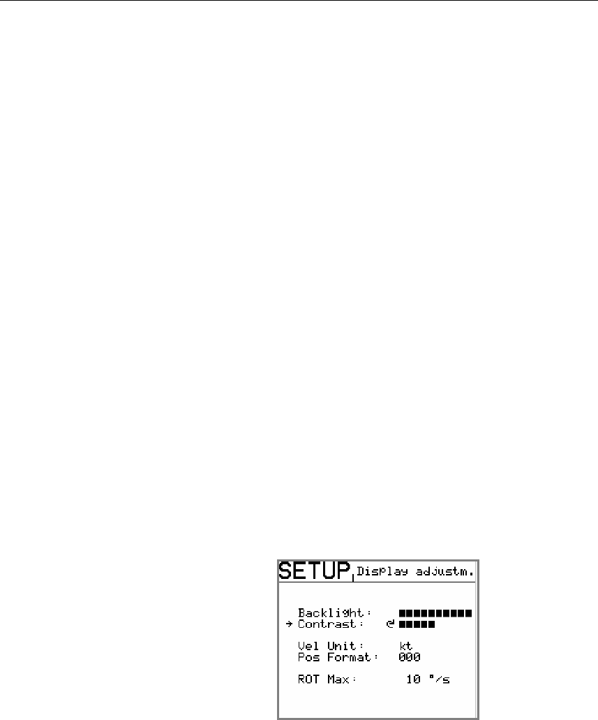
Display Adjustments
In the Display adjustments submenu the backlighting and
contrast of the display are adjusted. The format for velocity
(knots or m/s) and resolution on position displayed may be
specified, together with the maximum rate of turn (ROT) value
to be shown on the display. Default value for ROT is 20°/s.
When navigation information (NAV1 or NAV2 menu, refer
page 36) are selected, the display backlighting may be increased
or decreased by using the rotary knob.
Simrad HS50 Heading Sensor
26 20221081 / F
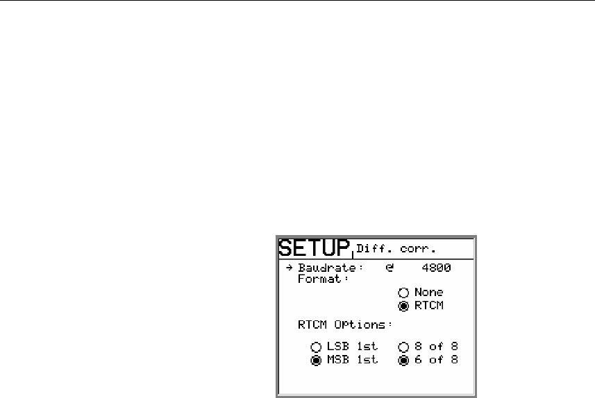
Differential corrections
The signal cable with the differential corrections is connected to
the terminal block P205 on the Processing unit for RS-422 input
signal, and P206 for RS-232 input signal.
In the Diff. corrections submenu the correct baud rate and
format for the signal must be set. If RTCM format is selected,
the correct RTCM Options must be selected to enable
differential corrections to be used in the position solution.
If data from more than one reference station are available on the
link, HS50 automatically uses the nearest reference station to
obtain the best solution. The default RTCM Option is MSB 1st
and 6 of 8.
INSTALLATION
20221081 / F 27
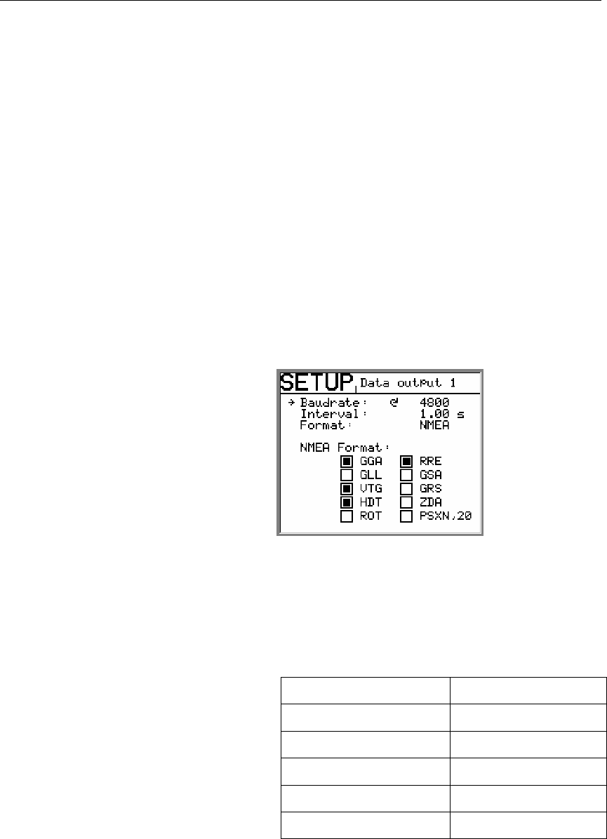
Data output
The Processing unit has two individually configurable output
serial lines.
On output line Data output 1 two RS-232 and two 422 serial
lines are available. The signal cables can be connected to both
terminal block P202 and P203.
On Data output 2 one RS-232 and one 422 serial lines are
available. The signal cables are to be connected to terminal
block P204.
Note! All six serial lines may be used simultaneously!
The setup of baud rate, interval between NMEA sentences and
output formats for each port are performed in the Data output 1
and Data output 2 submenu.
Baudrate: The rate at which bits are transmitted. 4800 is
standard NMEA rate.
Interval: Interval in seconds between each NMEA
sentence.
Example:
Interval setting Hz
1 sec 1 Hz
0.5 sec 2 Hz
0.2 sec 5 Hz
0.1 sec 10 Hz
0.05 sec 20 Hz
Format: Format on data output line. The following
selections are available: NMEA and none.
NMEA Format: NMEA sentences to be sent to output line.
WARNING! If “none” is selected as output format, no data will be
sent to output line.
Simrad HS50 Heading Sensor
28 20221081 / F
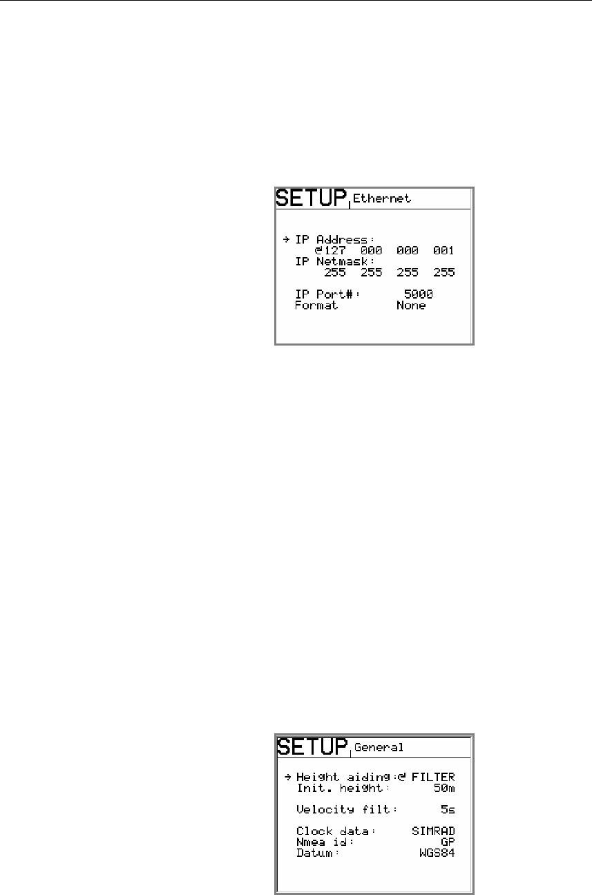
Ethernet
The Processing unit can output data on Ethernet from terminal
J60. In the Ethernet submenu the IP address, netmask, IP port
number and output format have to be specified. For the NMEA
format the messages GGA, GLL, VTG, HDT, ROT and RRE are
included.
IP Address: Default setting: 010 000 021 030.
IP Netmast: Default setting: 255 255 255 000.
Format: Format on Ethernet line. The following
selections are available: NMEA and None.
WARNING! If “None” is selected as output format, no data will be
sent to Ethernet line.
Caution! A change in IP Address and IP Netmask parameter will not
take effect before the HS50 is restarted!
Note! The cable to be used has to be a crossed Ethernet cable.
General
The General submenu includes selection of height aiding,
velocity filtering, Clock data, NMEA id and Datum.

INSTALLATION
20221081 / F 29
Height aiding
For operations with weak satellite geometry the position output
can be made more accurate by using height aiding. For normal
operation height aiding should be set to Filter or Off. When
Filter or Fixed is selected, an initial height has to be entered.
The value to be entered in Init. height is the GPS height value
HGT shown in the position display window no. 1, refer page 36,
average over some minutes.
Note! Height aiding is active only with input of differential GPS.
Velocity filtering
The HS50 output raw data for SOG and COG with the default
velocity filter value set to 3 sec. When smoothing of the SOG
and COG measurements are required the filter period could be
selected in the range 1 to 99 seconds in steps of one second.
With a high filter period more smoothing of the SOG and COG
measurements will be achieved and the response to speed and
course changes gets slow.
Radar format
On the Processing unit terminal P208 output to radar is available
(AD-10 format. The default setting is OFF.
NMEA ID
The NMEA ID for the HS50 output lines can be selected
between the following IN, HE, HC, GP and TI. The default
setting is IN (Inertial Navigation).
Datum
For the position Datum, only the WGS-84 is available.
Simrad HS50 Heading Sensor
30 20221081 / F
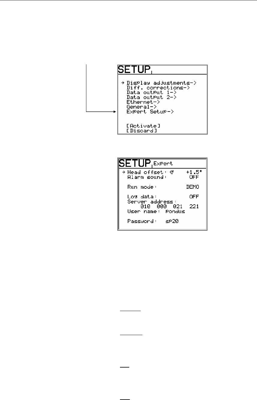
Expert setup
By pressing the SETUP button twice and then holding this button
for 5 seconds, an Expert Setup category will be available in the
SETUP menu.
Use the rotary knob to enter the SETUP Expert submenu.
The following settings are available:
Head offset: Used for correcting a constant heading offset.
Refer Heading offset, page 31.
Alarm sound: Used for turning alarm text and alarm sound
on and off. Refer Alarms, page 39.
The following selections are available:
POS-Q
Only invalid position will activate alarm.
HDT-Q
Only invalid heading will activate alarm.
HDT-Q is the default setting.
All
Both invalid position and invalid heading will
give alarm.
Off
Used for tuning off all alarm text or alarm
sound.

INSTALLATION
20221081 / F 31
Run mode: Used for switching the HS50 between
NORMAL and DEMO mode.
DEMO mode is used for simulating input data
to the system.
WARNING! The HS50 must not be switched to DEMO mode when
the system is in operation!
Log data, Server address, User name and Password:
Used for service purpose.
Caution! A change in Expert setup parameters (except Head offset and
Alarm sound) will not take effect before the HS50 is restarted.
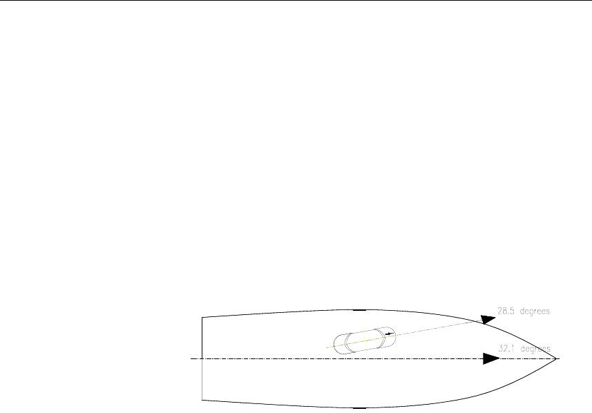
Heading offset
The Head offset feature allows you to correct for a constant
compass heading offset that may be present as a result of an off
axis misalignment between the Sensor unit and the vessel
alongships axis.
Note! It is important that the Sensor unit is mounted accurately in the
alongships direction so the Head offset value does not exceed
±5°. If the mounting orientation is not within these tolerances
the heading accuracy will be degraded. Instead of exceeding a
Head offset value of ±5° the Sensor unit orientation should be
adjusted mechanically.
The system has to be calibrated on board the vessel after
installation. A typical calibration consists of calibrating the
direction of GPS antennas within the Sensor unit against an
external reference. Type of reference must be decided according
to the required accuracy. Alternative references for calibrating
the heading offset of the Sensor unit could be:
• The heading of the pier or quay the vessel is moored to.
• An external compass reading like from a gyro compass.
• Two fixed points on the chart that the vessel is sailing
between.
The observation period for the heading difference should
continue for an as long as possible period in order to eliminate
errors in the HS50 measurements caused by multipath effects.
These may be particularly pronounced in the static conditions of
a harbor area.
Simrad HS50 Heading Sensor
32 20221081 / F
The average value for observations from each of the two
different systems should then be used, and the offset between
the two systems (reference value minus HS50 reading) input as
the Head offset value.
The offset value can be either positive or negative.
Example:
If the heading measured by the reference system is 32.1° and the
HS50 heading 28.5° during the calibration period, 3.6 (32.1 -
28.5) should be entered in the General submenu as the Head
offset value.
OPERATING INSTRUCTIONS
20221081 / F 33
4. OPERATING INSTRUCTIONS
4.1 Overview
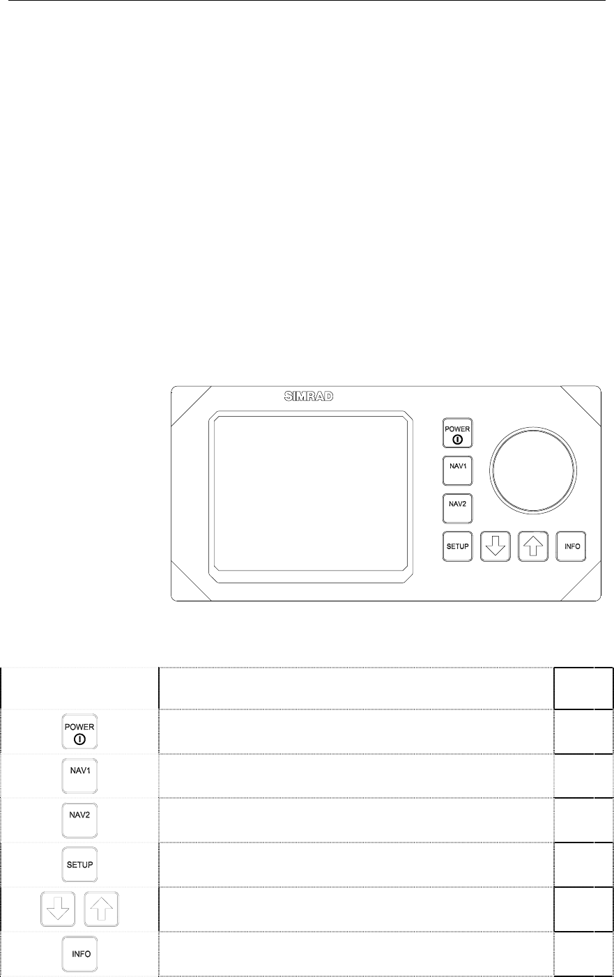
The Display unit is used for setup and operation of the HS50.
Each of the push buttons is clearly identified with the primary
function in large text, and a secondary function listed in smaller
text. Each button provides you with the ability to access a
primary display, a secondary display and/or multiple function
displays.
Adjustable settings are provided in the SETUP mode. The
settings allow adjustment of mounting orientation, selection of
differential correction, setup of output serial line formats,
Ethernet and the display. Refer Software setup procedure, page
21.
POS
HDT
pfjo^a=epRM
The Display unit consists of the main elements as listed below.
FUNCTION REF.
PAGE
Power on/off. 34
HDT
Displays Navigation/HDT display with compass rose or
details. 36
POS Displays Navigation/POS with position and accuracy ellipse. 36
Displays SETUP menu. 21
Used for maneuvering in the SETUP submenus. 21
Used for displaying additional system information. 37
Simrad HS50 Heading Sensor
34 20221081 / F
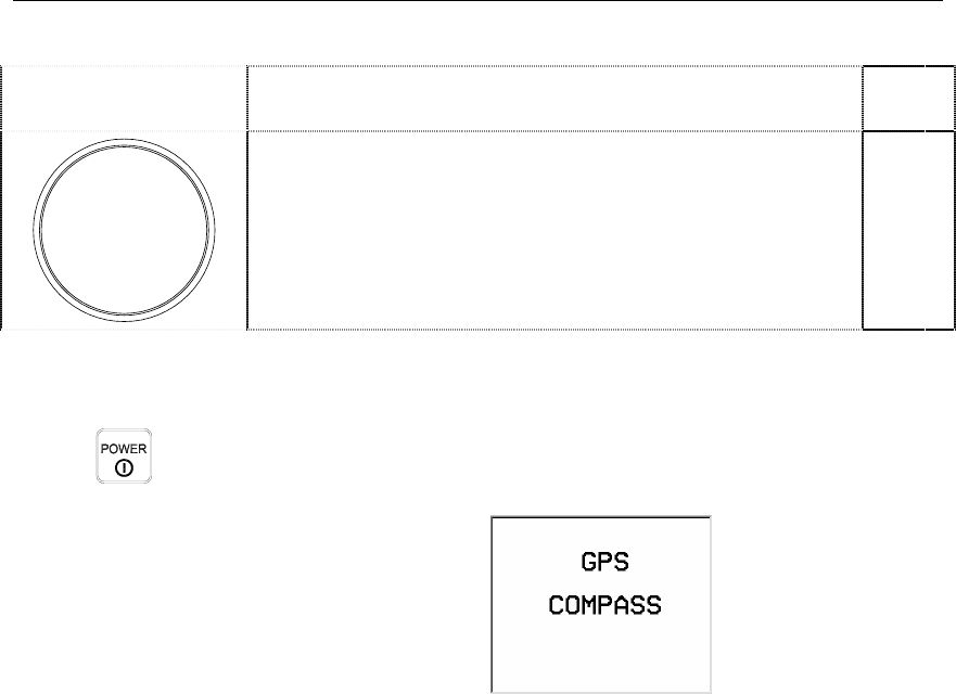
FUNCTION REF.
PAGE
The rotary knob is used for entering values in SETUP
submenus, and for adjusting the display brightness. 21
4.2 Turning the system ON/OFF
A single press on the POWER button switches the system ON,
and the following start up information is shown on the display:
Once installed, calibrated and started, the HS50 needs no
manual intervention during operation.
After power on, up to 15 minutes is needed to obtain full
accuracy on all data. Since there normally is no reason for
turning the unit off, it should be left running continuously.
The HS50 will be shut down in a controlled way when the
POWER button is pressed for 1-2 seconds. Then the message
Shutdown in process will appear on the screen. If the POWER
button is pressed and held for 5 seconds or more, the system is
shut down immediately. Typically used if the system has a hang-
up and does not respond on any commands. The configuration
of HS50 is however stored on the internal flash disk independent
on how the unit is powered off.
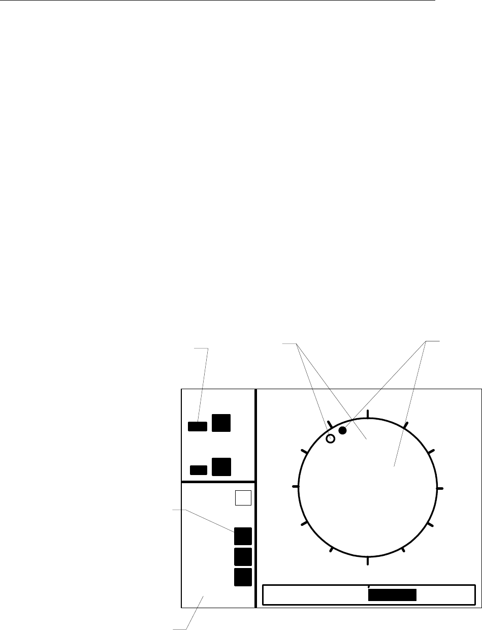
4.3 Performance monitoring
The navigation display NAV1 and NAV2 includes on the left
side of the screen data quality and status information. The
indicators are as follows:
• HDT-Q. The quality of the heading measurements. Two
black bar graphs indicate normal accuracy, one black and one
white bar graph indicate reduced accuracy and two white
invalid heading.
OPERATING INSTRUCTIONS
20221081 / F 35
• POS-Q. The quality of the position measurements. Two
black bar graphs indicate normal accuracy, one black and one
white bar graph indicate reduced accuracy and two white
invalid position.
• DIF. Indicated whether differential corrections are input and
used in the position determination or not. A black box
indicates that differential corrections are used. A white box
indicates no use of differential corrections.
• COG. A black box indicates valid COG calculation, a white
an invalid calculation.
• SOG. A black box indicates valid SOG calculation, a white
an invalid calculation.
• ROT. A black box indicates valid ROT calculation, a white
an invalid calculation.
• WGS84. Shows the Datum used for the position and velocity
determination. If the text DEMO appears in this field the
system is operating in demonstration mode with simulated
output data.
348 090
270
000
PS
ROT 0.6 º/s
DIF
HDT-Q
POS-Q
COG
True
heading
COG
Bargraph
showing
quality
Bargraph
showing
quality
336
SOG
ROT
WGS84
Datum or
operation
mode
An invalid HDT-Q status indication will be shown after 300
seconds of loss of GPS heading in the system, and the output of
heading data will terminate. In the first 300 seconds after loss of
Simrad HS50 Heading Sensor
36 20221081 / F
GPS heading, the heading output is determined from the inertial
element.
The data quality status information indicated on the Display unit
is also included in some of the NMEA messages that can be
output on the serial lines.
Navigation/HDT display
HDT
When pressing the NAV1/HDT button, the HS50 will toggle
between two different displays for heading information.
Primary NAV1/HDT display, shown after the start-up screen
when the HS50 is turned ON.
True heading is shown as a big number in the center of the
compass with the COG value above it.
Secondary NAV1/HDT display.
This display shows heading, course over ground and speed over
ground values in big characters.
Navigation/POS display
POS
The HS50 will toggle between three different displays for
position information when the NAV2/POS button is pressed.
Primary display shown when the NAV2/POS button is pressed
once. The display shows main navigation information.
Secondary NAV2/POS display.
The display presents position information in large numbers.
OPERATING INSTRUCTIONS
20221081 / F 37
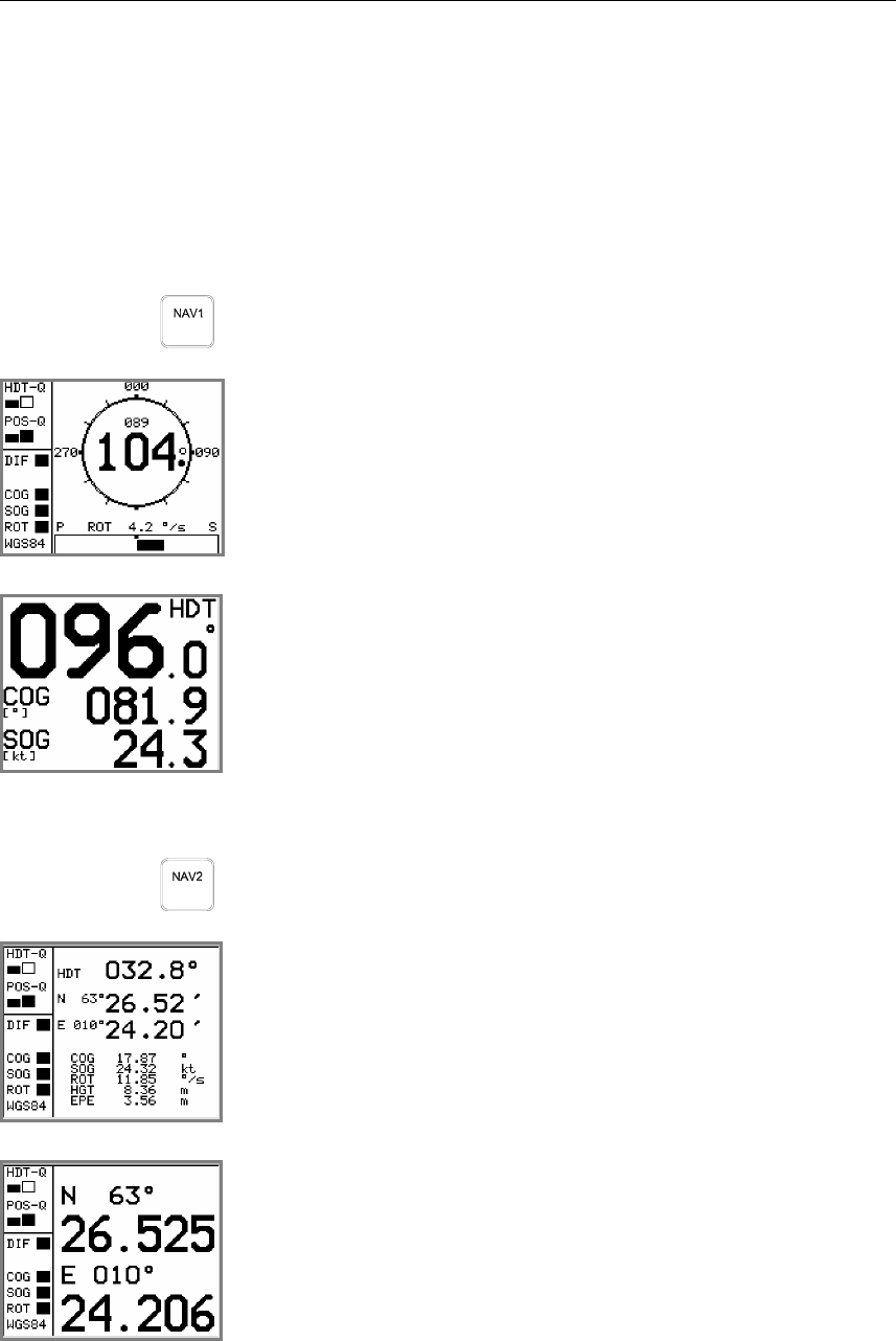
Third NAV2/POS display: the Satellite skyplot.
This display shows satellites in sight by the Sensor unit, and
which satellites the HS50 is tracking. The satellites are presented
according to satellite geometry. The bars on the left side of this
display indicate the signal-to-noise level for each satellite.
Info displays
When pressing the INFO button, the system will page through a
number of displays for information about system configuration
and performance. The information on some of these displays is
mainly used for troubleshooting the system.
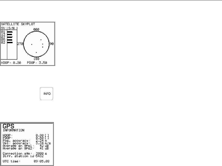
In the GPS information display details for the position solution
is presented. This information is mainly for trouble shooting of
the system.
An explanation of the information shown is as follows:
HDOP
PDOP Quality indicators for the GPS solution.
Pos. accuracy Estimated accuracy on the position solution (RMS).
Vel. Accuracy Estimated RMS accuracy on the velocity solution (RMS).
Average sn gps1
Average sn gps2 Average signal-to-noise ratio on the GPS receiver 1 and 2.
Correction age Age of differential corrections. If HS50 receives no differential
correction, the displayed correction age will be high. See No
Differential corrections, page 47 for trouble shooting loss of
differential signal.
Diff. Station id Actual reference station utilized in the position solution.
UTC time World time referred to UTC.
Simrad HS50 Heading Sensor
38 20221081 / F
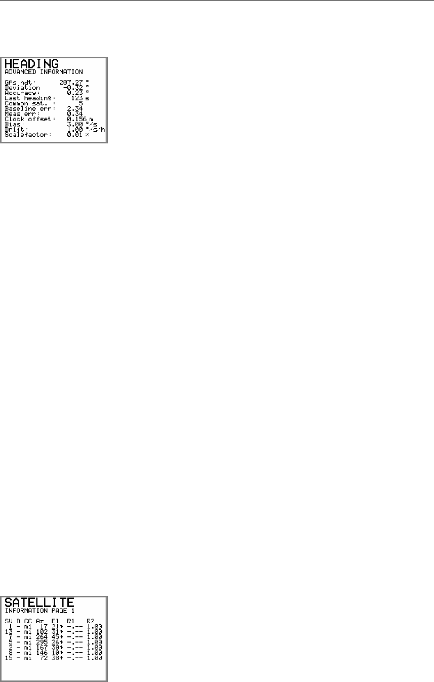
In this display, a number of additional information on the
heading solution is presented. This information is mainly used
for troubleshooting the system.
An explanation of the information shown is as follows:
Gps hdt The heading determined from GPS alone.
Deviation The difference in heading determined from GPS and the internal
gyro element.
Accuracy The instantaneous heading accuracy determined from GPS
alone. The instantaneous accuracy might differ from the
specified accuracy which is a figure determined for the
combination of GPS heading and heading from the internal data
element. The specified accuracy figure for the product is also
calculated as a standard deviation over a number of samples.
The figure shown as Accuracy might occasionally be higher
than the specified heading accuracy. If the Accuracy figure
shown is much higher (3 times or more) than the specified
accuracy, then the performance of the system is poor. Check
Reduced heading indication, page 48 in this manual for
troubleshooting the system.
Last heading This is the time since the system calculated the GPS heading. If
GPS signals drops out this figure will increase. In the first 300
seconds after loss of GPS heading, the heading output is
determined from the inertial element. After 300 seconds of loss
of GPS heading in the system the output of heading data will
terminate. If so, see Invalid Heading, page 47 for trouble
shooting the system.
Common sat. Shows the number of common satellites seen by the two GPS
antennas. The number of common satellites have to be two or
higher to determine heading. If the number is less than two, see
Invalid Heading, page 47 for trouble shooting the system.
The other information in this display is only of interest to
service personnel.
Number of satellites used in the GPS position fix with indication
of increasing or decreasing azimuth (Az) and elevation (El).
This display is mainly used by service personnel.
OPERATING INSTRUCTIONS
20221081 / F 39
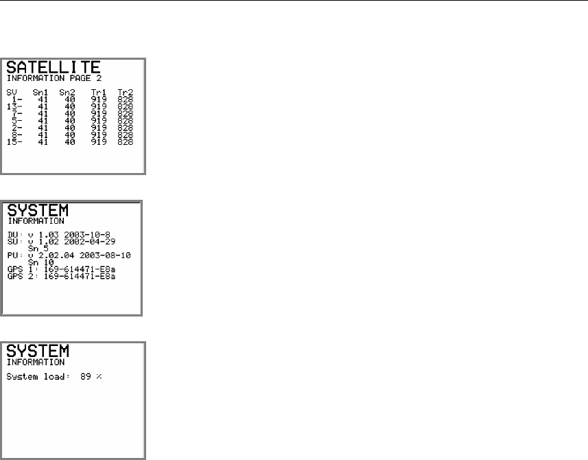
Number of satellites used in the GPS position solution and the
number of satellites tracked by GPS antenna no. 1 (Tr1) and 2
(Tr2).
This display is mainly used by service personnel.
Software version for each unit (Distribution Unit = DU, Sensor
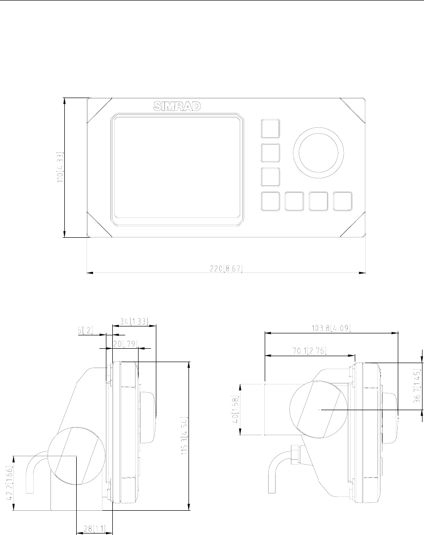
Unit = SU and Processing Unit = PU), together with internal
serial number for Sensor and Processing unit. The date behind
each unit’s software version refers to manufacture date for the
unit.
System load as percentage of used CPU capacity.
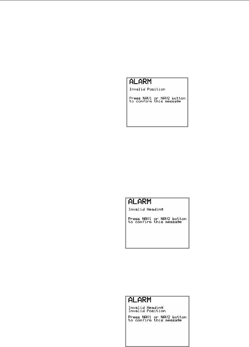
4.4 Alarms
The HS50 will generate an acoustic alarm and an alarm text if
heading or position information is invalid or missing.
The acoustic alarm will sound for 5 seconds, and the alarm text
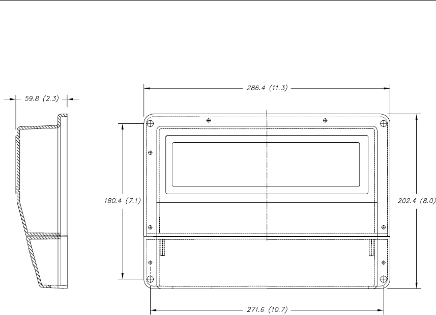
will remain in the display until the NAV1 or NAV2 button is
pressed. No data will be output from HS50 as long as the alarm
situation is present.
If the SETUP menu is active when the alarm condition arises,
the alarm text will be displayed when the SETUP menu is left.
Note! No alarm will be activated if the system is setup to not respond
to alarm situations. Refer Expert setup, page 30.
Simrad HS50 Heading Sensor
40 20221081 / F
Invalid Position alarm
Activated if the system has been unable to determine position
the last two seconds, or if the HDOP value is greater than 4.
See No valid data, page 46 for troubleshooting.
The following alarm text will be displayed:
Invalid Heading alarm
Activated 300 seconds after the system is unable to determine
GPS heading and the HDT-Q indication has become invalid.
Invalid Heading, page 47 for troubleshooting.
The following alarm text will be displayed:
Invalid Position and Heading alarm
If both heading and position data is invalid, the display will
show:

OPERATING INSTRUCTIONS
20221081 / F 41
4.5 Operation
The HS50 will normally output signals on the serial lines
without any involvement from the user. However, the following
should be taken into consideration during operation:
Height aided GPS position
In periods with weak satellite geometry, the position can be
made more accurate by using height aiding function in the
General submenu. Refer General, page 28.
The height aiding improves the solution by using the knowledge
that a vessel at sea has only small short-term variations in height
caused by heave. The long-term variations caused by tide are
taken care of in the system. The height value used, as input to
the GPS solution is a low-pass filtered value of the measured
height.
A start value for the low-pass filter should be specified for use at
system start-up. The value to use is the height of the Sensor unit
above the WGS-84 ellipsoid when the sea level is at its mean
value. This height can be found in the primary Navigation/POS
display, where the HGT value is the GPS height. Refer
Navigation/POS display, page 36. The value should be
monitored for some minutes, and the average value should be
used.
Note! The height difference between mean sea level and the WGS-84
ellipsoid can be significant. Values between +/- 100 meters can
be encountered.
For normal operation, height aiding should be set to FILTER or
OFF. When FILTER or FIXED is selected, an initial height
has to be entered.
Height aiding is active only with input of differential GPS.

Simrad HS50 Heading Sensor
42 20221081 / F
THIS PAGE INTENTIALLY LEFT
BLANK

MAINTENANCE
20221081 / F 43
5. MAINTENANCE
5.1 General
Service on the HS50 hardware in the field can consist of:
• Replacing damaged cables
• Replacing failed Sensor unit
• Replacing failed Processing unit
• Replacing failed Display unit
The Sensor unit is not designed for service in the field and
opening the housing will result in damage or degradation of the
unit and void the warranty. A failed Sensor unit has to be
shipped back to Simrad in the original transportation box or
another appropriate box for service. The return address is
provided in the last pages of this manual.
The software in HS50 can be upgraded to latest version in the
field by connecting an external PC to the Processing unit. A
software upgrade has to be performed by Simrad service people
or representatives.
5.2 Periodic maintenance
The user should execute all necessary maintenance. This
includes normal cleaning of all units and inspection of cables
and connectors at intervals. Components which malfunction
should either be replaced or sent back to Simrad for service.
The periodic maintenance of the HS50 components is as
follows:
Sensor unit
Make a visual inspection at 2-3 months intervals, and at the start
of each season.

Simrad HS50 Heading Sensor
44 20221081 / F
Re-calibration of the Sensor unit
The direction of the Sensor unit relative to the vessel's heading
has to be recalculated only if the Sensor unit has been moved or
dismounted from its holder. Then the calibration procedure
described in General section, page 28 has to be followed for re-
calibration of the heading.
Processing unit
No special maintenance is required. It is advisable, however, at
the start of each season to make a visual inspection of the
terminals below the bottom cover (terminal cover) and check all
connections.
Display unit
The Display unit will under normal use require little
maintenance.
If the unit requires any form of cleaning, use fresh water and a
mild soap solution (not a detergent). It is important to avoid
using chemical cleaners and hydrocarbons such as diesel, petrol
etc.
Make sure that all open connectors on the Display unit are fitted
with a protection cap.
It is advisable at the start of each season to check all connections
to the unit and cover with Vaseline or WD40. If the Display unit
is not removed from the vessel, it should be covered with the
white protection cover.
Software upgrades
Software upgrades with improvements and new functionality
will regularly be offered. Download of new software version is
performed from an external PC by utilizing the Ethernet port on
the PC and the HS50 Processing unit. Some new software
releases will also require a new PROMM installed in the
Display unit.

MAINTENANCE
20221081 / F 45
5.3 Repairs and modifications
Repair of the HS50 units is limited to replacement of damaged
cables, Sensor unit, Processing unit, or Display unit.
Replacing damaged cables
Power off the Processing unit and dismount the damaged cable.
If the connector is not damaged it may be re-used, else a new
connector has to be made available.
Assemble the connector to the new cable as described in the
wiring information for the damaged cable. Refer the
INSTALLATION section, page 9 onwards.
Terminate the cable to the Processing unit as described in Cable
connections, page 19.
Replacing damaged units
No HS50 units are designed for service in the field, and a
damaged unit has to be shipped back to Simrad for repair.
Caution! Opening the Sensor unit housing may result in permanent
damage to the unit!
Install the new unit according to procedures described in the
INSTALLATION section, page 9 onwards.
5.4 Troubleshooting
A GPS compass is a complex system and performance is
dependent of a proper installation and a successful sea trial.
In case of a failure, the user will be helped by the Display unit,
which contains several test features that will assist you in
isolating a probable fault.
Pressing any button resets the audible alarm. The visual alarm
will remain and alternate with the operating display until the
fault has been rectified. Refer to the table below for hints and try
to solve the problem yourself, or consult your nearest Simrad
dealer for assistance.
The next sections contain some hints for troubleshooting.

Simrad HS50 Heading Sensor
46 20221081 / F
No response
In normal operation it takes about one minute from the Display
unit is powered on until information appears in the display. If
the display screen is still black after three minutes from power
on, do as follows:
• Check the power connection to the Processing unit, and
check that the Processing unit is supplied with correct
voltage. Refer specification in Power section, page 7.
• Press the POWER button on the Display unit two or three
times in case of poor connection.
If there are still no information on the display, consult your
nearest Simrad dealer for assistance.
No valid data
In normal operation it can take up to 15 minutes from the
Display unit is powered on to full accuracy on all data is
obtained, and the indicators showing valid data. If all the
indicator boxes are still white after 15 minutes from power on,
then do as follows:
• Check that connectors are properly connected to Display unit
and Sensor unit.
• Check that cables from Sensor unit and Display unit are
correctly terminated to the Processing unit according to the
pin-out shown on page 20.
• Check that the cables are correctly terminated in the
connectors. Refer Cable wiring, page 13 for the Sensor unit,
and Display unit cable page 17 for the Display unit. If not,
switch off the power, re-connect the cable to the connectors
properly, and power on the unit again.
• If all connections are correct and still no valid data, the
mounting location of the Sensor unit may not be suitable, less
than four satellites are in view, or there may be an
obstruction between the Sensor unit and the GPS satellites.
Check the mounting location and consider relocation
according to Location of the unit, page 10.
If there are still no valid data, consult your nearest Simrad dealer
for assistance.

MAINTENANCE
20221081 / F 47
No Differential corrections
The possible reason for a white box for differential correction
indication (DIF) could be one of the following:
• No differential corrections are input through terminal port
P205 or P206 on the Processing unit. If differential
corrections are input through one of these terminal ports,
check that the parameters are properly set up in the Display
unit setup menu Diff. input, see Differential corrections,
page 26.
• You can be out of range to a radio reference station and the
differential corrections are therefore missing. If the reference
station is too far away or it is in the shadow of geographical
obstructions or other equipment on board, reception may be
unreliable or missing. Pressing the INFO button and the
display GPS Information shows the identification number of
the reference stations connected to the HS50.
• The reference station can be out of function. Check the status
of the reference station with the authorities responsible for it,
or consult your nearest Simrad dealer for assistance.
Invalid Heading
The possible problem can be one of the following:
• The number of GPS satellites the Sensor unit is able to see is
too few. Press the NAV2/POS button until the Skyplot view
appears. Check that at least four satellites are available and
that the PDOP value is less than 6. Refer Satellite Skyplot
display, page 37. Check also the number of common
satellites seen by the two GPS antennas by pressing the INFO
button and looking at the value for Common sat. in the
advanced heading information display as shown in page 38.
The number of common satellites have to be two or higher to
determine a heading.
If one of the criteria's above is not fulfilled, the mounting
location of the Sensor unit may not be suitable or there may be
an obstruction between the Sensor unit and the GPS satellites.
Check the mounting location and consider relocation according
to Location of the unit, page 10.
If it is still not working after checking the above items, consult
your nearest Simrad dealer for assistance.
Simrad HS50 Heading Sensor
48 20221081 / F
Reduced heading indication
The reason for reduced heading performance could be one of the
following:
• The number of GPS satellites the Sensor unit is able to see is
too few. Press the NAV2/POS button until the Skyplot view
appears. Check that at least four satellites are available and
that the PDOP value is less than 6. Refer Satellite Skyplot
display, page 37.
• Check also the number of common satellites seen by the two
GPS antennas by pressing the INFO button and looking at the
value for Common sat. in the advanced heading information
display as shown in page 38. The number of common
satellites have to be two or higher to determine a heading.
If one of the criteria's above not is fulfilled, it may be an
obstruction between the Sensor unit and the GPS satellites.
Consider moving the vessel to another location to see whether
that helps.
If it is still reduced after checking the above items, consult your
nearest Simrad dealer for assistance.
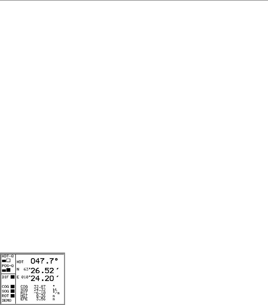
Simulated data
If the HS50 system is not sending out real data, check whether
the system is operation in demonstration mode with only
simulated output data. If the system operates in demonstration
mode the text DEMO appear at the bottom of the status field as
shown in the figure.
Refer Expert setup, page 30.

FIGURES AND DRAWINGS
20221081 / F 49
6. FIGURES AND DRAWINGS
This section contains outline drawings showing the mechanical
dimensions of the different HS50 parts. To scale drawings are
available upon request.
The following drawings are enclosed:
Name Drw. no Rev.
Sensor Unit, dimensions 3822-MA-015 1
Sensor Unit Bracket, dimensions 3822-MD-027 2
Sensor Unit Pedestal, dimensions 3822-MD-034 0
The following figures are enclosed:
Name Page
Processing Unit, dimensions 53
Display Unit, dimensions 54
Simrad HS50 Heading Sensor
50 20221081 / F
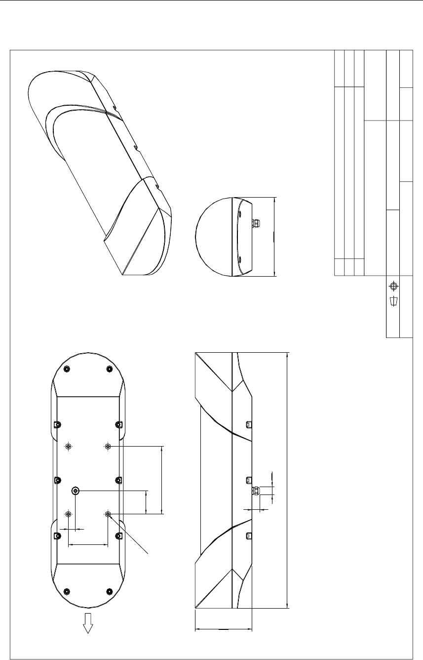
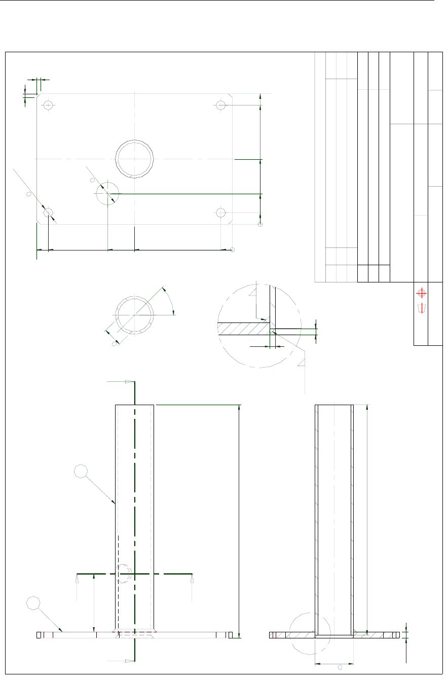
6.1 Sensor unit, dimensions
Approved :
Checked :
Subtitle:
Title :
Issued :
Drawing no:
Xref file :
Projection:
Rev. Description
Date:
Date, Sign.
Design by :
Usage:
Rev. no: Scale :
1
KL
KONGSBERG
SEATEX
M10 (4x)
Ship Heading and Navigation Sensor
Dimensions Sensor Unit
03.08.28
Assey
02.05.08
3822-MA-015
proj3munin/3822/technical
notes/mechanicaldesign/
sensorunit/ma015_00
1:5 A3
Material in Housing: Polyethylene
Weight : 8 Kg
Material in Nut`s and Screw`s : Stainless steel DIN 316
BOW
1BOW
850
205
225
77,5
140
25
262
27
27
FIGURES AND DRAWINGS
20221081 / F 51
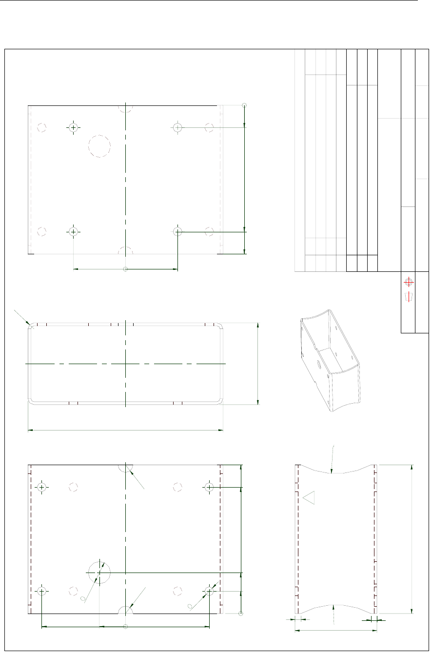
6.2 Sensor unit bracket, dimensions
Approved :
Checked :
Subtitle:
Title :
Issued :
Drawing no:
Xref file :
Projection:
Rev. Description
Date:
Date, Sign.
Design by :
Usage:
Rev. no: Scale :
Weight
Description
Tolerance: ISO 2768-M if not specified on drawing
No. Pos. Material
2
KL/HW
Material : Aluminium AISI 5052
Wall tickness: 4,0 mm
Colour : Grey RAL 7032
Ship Heading and Navigation Sensor
Sensor Unit Bracket Symmetrical Style
01.04.30 02.02.22 1:2
Detail
3822-MD-027
proj3munin/3822/technical
notes/wp7mechanical design/
sensorunit/md027_02
1
035 112,5112,5
30
12
R10
R10
030 55 170 200
110
262
R8
07070
030170200
110
88
200
R100
R100
KONGSBERG
SEATEX
Simrad HS50 Heading Sensor
52 20221081 / F
6.3 Sensor unit pedestal, dimensions
Approved :
Checked :
Subtitle:
Title :
Issued :
Drawing no:
Xref file :
Projection:
Rev. Description
Date:
Date, Sign.
Design by :
Usage:
Rev. no: Scale :
Weight
Description
Tolerance: ISO 2768-M if not specified on drawing
No. Pos. Material
0
KL
KONGSBERG
SEATEX
3822-MD-034
Ship Heading and Navigation sensor
Sensor Unit Pedestal
1:2 (A3)
Detail
1
2
1
1
02.05.06
02.05.06
proj3Munin/3822/Technical
notes/WP7Mechanical
design/sensor unit
C
4 X 4
3.5 X 4
1
2
Alu. plate T=8.0mm EN-AW 6082-T6
Alu. tube ø50x3.5 EN-AW 6082-T6
A
ASECTION A-A
BB
SECTION B-B
76 ±3
015 40 85 155
170
015 127,5 162,5 240
255
30
12(4x)
304
8+1
-0.5
300
DETAIL C
4
3,5
5
5
45°
50
25
FIGURES AND DRAWINGS
20221081 / F 53
6.4 Processing unit, dimensions
Simrad HS50 Heading Sensor
54 20221081 / F
6.5 Display unit, dimensions
Note! Mounting bracket is optional

PARTS LIST
20221081 / F 55
7. PARTS LIST
7.1 Standard delivery
The standard HS50 consists of:
Part no. No. Description
20212858 1 HS50 Sensor unit, including 1 meter cable and 4 fastening bolts
22084289 1 HS50 Processing unit including 4 fastening screws
20212759 1 HS50 Display unit, including 15 meter cable, flush mounting
kit and protecting cover
20212940 1 30 meter cable
20213054 1 HS50 Standard English documentation, including cut-out
templates and Quick Reference guide.
7.2 Optional equipment
The HS50 can be delivered with following optional equipment:
Part no. Description
20213039 HS50 Sensor Unit Mounting Bracket
20213021 HS50 Sensor Unit Mounting Pedestal
22084941 Mounting bracket for Display unit
7.3 Documentation
The HS50 system includes English documentation only, and
national documentation has to be ordered separately.
All national documentation includes a Quick Reference Guide.
The following documentation can be delivered:
Part no. Description
20213245 HS50 Documentation, Swedish
20213252 HS50 Documentation, Spanish
20213609 HS50 Documentation, Italian
