Sindoh TWFM-M311D Wireless LAN module User Manual
Sindoh Co., Ltd. Wireless LAN module Users Manual
Sindoh >
Users Manual
User Manual
PRODUCT NAME : Single Band 1T1R Wi-Fi Module
MODEL NAME : TWFM-M311D
Designed Checked Approved
LG Innotek Co., Ltd.
J.H. Moon S.C. Lee S.D. Choi
DOCUMENT No. -
2014.04.08 2014.04.08 2014.04.08 PAGE 9
(00)-0073
The information contained herein is the exclusive property of LG Innotek
and shall not be distributed, reproduced or disclosed in whole or no in part
without prior written permission of LG Innotek.
S P E C I F I C A T I O N
PAGE :
DOCUMENT No. : -
REG. DATE : 2014.04.08
MODEL NAME : TWFM-M311D
REV. DATE : 2014.04.08
REV.NO : 1.00
©2014 LGIT. All rights reserved.
Table of Contents
No. Description Page
1 Features 2
2 Ordering Information 2
3 Label Marking 2
4Storage Test Conditions 3
5 Operating Test Conditions 4
6 Standard Test Conditions 4
7 Block Diagram 5
8 Pin Description 6
9 Test Method 7
10 Outline Drawing 9
1 / 9
S P E C I F I C A T I O N
PAGE :
DOCUMENT No. : -
REG. DATE : 2014.04.08
MODEL NAME : TWFM-M311D
REV. DATE : 2014.04.08
REV.NO : 1.00
©2014 LGIT. All rights reserved.
2. Ordering Information
Model Description
TWFM-M311D Wi-Fi Module, Single Band 1T1R
1. Features
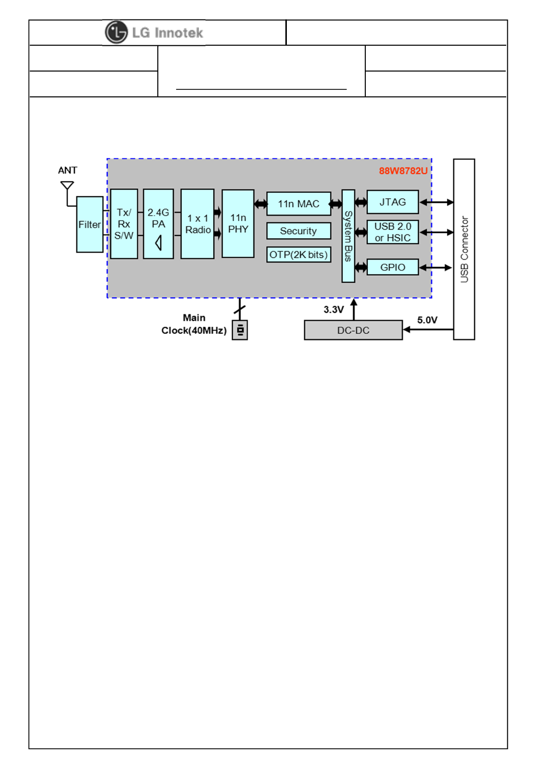
TWFM-M311D is the small size and low power module for IEEE 802.11b/g/n wireless
LAN. TWFM-M311D is based on Marvell 88W8782U solution.
IEEE 802.11 b/g/n single band WLAN infrastructure
Size : 37.0 x 28.0 x 3.7 mm
2.4GHz internal PA
1T1R mode with 150Mbps PHY rate for both transmit and receiving
Pattern printed antenna
Use on-chip OTP(One-Time Programmable)
USB 2.0
Supports drivers for Linux
Security : Supports 802.11i security standards
(AEC/CCMP, WEP/TKIP, AES/CMAC, WAPI)
Application: DTV, DVD Player, Blue-ray Disk Player, STB, Printer, etc.)
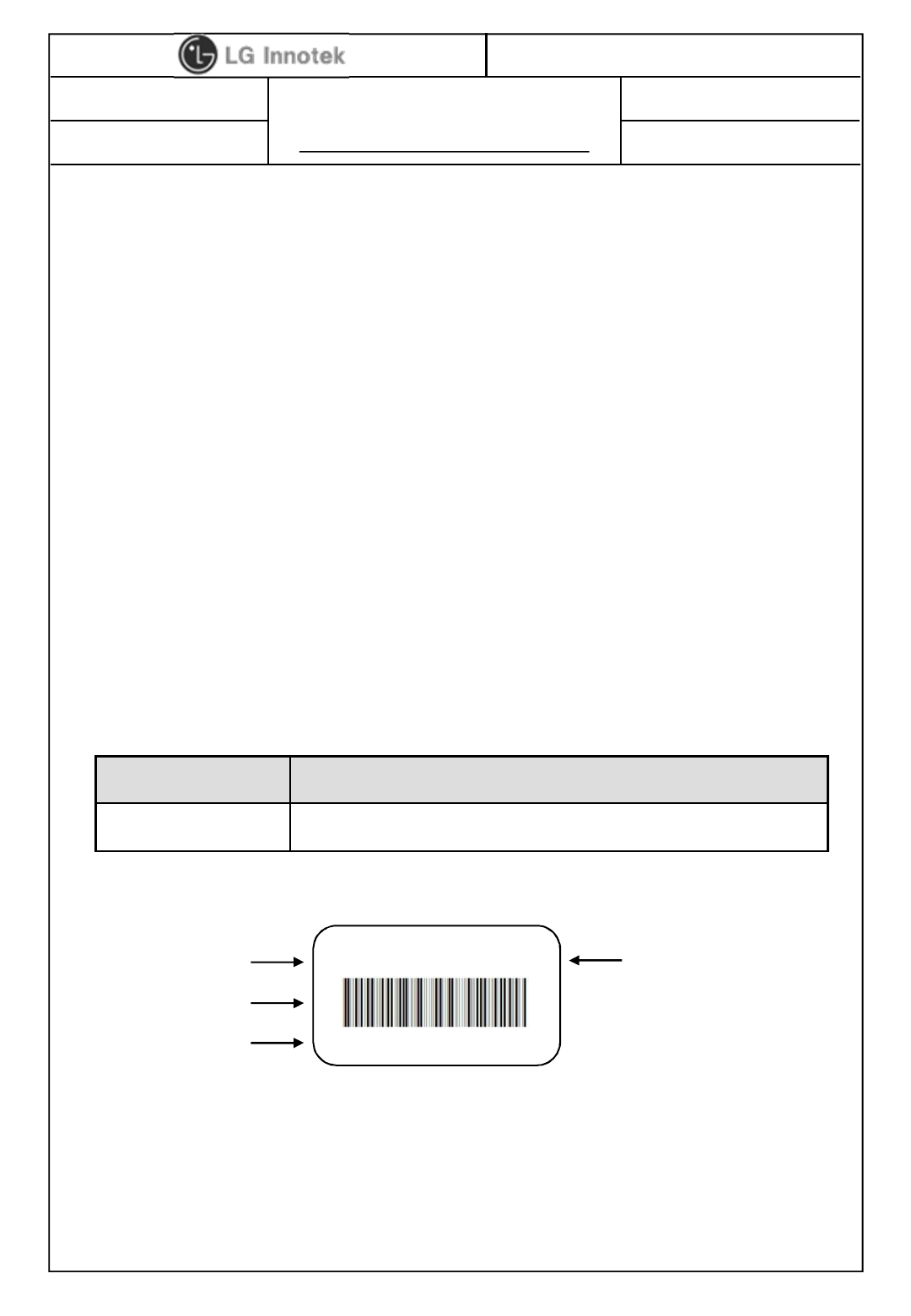
3. Label Marking
①Model No.
②MAC Address BAR Code(except for OUI)1)
③MAC Address No.
④Product Lot No. : 1301A1201
- 13 : Year
- 01 : Month
- A : Revision No.
- 12 : Date
- 01 : Manufactured process
①
②
③
1301A1201
001EB2B00339
TWFM-M311D ④
1) OUI : Organizationally Unique Identifier
2 / 9
S P E C I F I C A T I O N
PAGE :
DOCUMENT No. : -
REG. DATE : 2014.04.08
MODEL NAME : TWFM-M311D
REV. DATE : 2014.04.08
REV.NO : 1.00
©2014 LGIT. All rights reserved.
Parameter Min Max Unit
Storage Temperature -10 +80 ℃
Storage Humidity (@ 40℃) - 90 %
Caution : The specifications above the Table define levels at which permanent damage
to the device can occur. Function operation is not guaranteed under these conditions.
Operating at absolute maximum conditions for extend periods can adversely affect the
long-term reliability of the device.
※Other conditions
1) Do not use or store modules in the corrosive atmosphere, especially where
chloride gas, sulfide gas, acid, alkali, salt or the like are contained. Also, avoid
exposure to moisture.
2) Store the modules where the temperature and relative humidity do not exceed
5 to 40℃and 20 to 60%.
3) Assemble the modules within 6 months. Check the soldering ability in case of
6 months over.
4. Storage Test Conditions
3 / 9
S P E C I F I C A T I O N
PAGE :
DOCUMENT No. : -
REG. DATE : 2014.04.08
MODEL NAME : TWFM-M311D
REV. DATE : 2014.04.08
REV.NO : 1.00
©2014 LGIT. All rights reserved.
Parameter Min Typ Max Unit
Operating Temperature 0 - +60 ℃
Operating Humidity (40℃) - - 85 %
Supply Voltage +4.75 +5.0 +5.25 Vdc
The Test for electrical specification shall be performed under the following condition
Otherwise this following conditions, not guaranteed this performance.
5. Operating Conditions
Temperature 25 ±5℃
Humidity 65 ±5%
Input power Supply Voltage
+5.0V +5.0V ±5%
6. Standard Test Conditions
6-1. Ambient condition
6-2. Power supply voltages
6-3. Current consumption
Current Consumption Min. Typ. Max. Unit
TX Mode ( MCS7) - - 500
mA 1)
Idle and Associated state - - 180
Radio disabled state - - 70
Note 1 : This figure is the RMS(root mean square) value.
4 / 9
S P E C I F I C A T I O N
PAGE :
DOCUMENT No. : -
REG. DATE : 2014.04.08
MODEL NAME : TWFM-M311D
REV. DATE : 2014.04.08
REV.NO : 1.00
©2014 LGIT. All rights reserved.
7. Block Diagram
5 / 9
S P E C I F I C A T I O N
PAGE :
DOCUMENT No. : -
REG. DATE : 2014.04.08
MODEL NAME : TWFM-M311D
REV. DATE : 2014.04.08
REV.NO : 1.00
©2014 LGIT. All rights reserved.
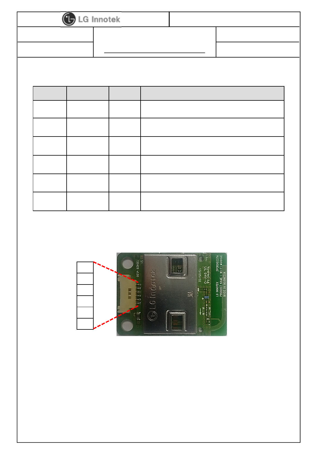
8. Pin Description
Pin No. Pin Name I/O Pin Description
1 VCC I VDD 5.0V
2 D- I/O USB Communication signal USB_DN
3 D+ I/O USB Communication signal USB_DP
4 GND - GND
5 WOW I Wake-up WLAN
6 NC I Shielding GND
< TOP View >
Note.
1) Recommend a module install sequence for prevent USB device failure
- Supply 5.0V power and GND
- Connect to data signal (USB_DP, USB_DN)
2) If remove the module, proceed in reveres sequence
3) Connector ⓐ: (CONN 12507WR-06L, YEONHO ELECTRONICS CO., LTD.)
6
5
4
3
2
1
6 / 9
S P E C I F I C A T I O N
PAGE :
DOCUMENT No. : -
REG. DATE : 2014.04.08
MODEL NAME : TWFM-M311D
REV. DATE : 2014.04.08
REV.NO : 1.00
©2014 LGIT. All rights reserved.
LitePoint
IQnxn
TESCOM
Shield Box
USB Cable
(Control, GND)
10dB ATT +
Power Splitter
Linux
RF Cable
Power Supply
Power Cable
( +5.0V, GND) Windows
Control
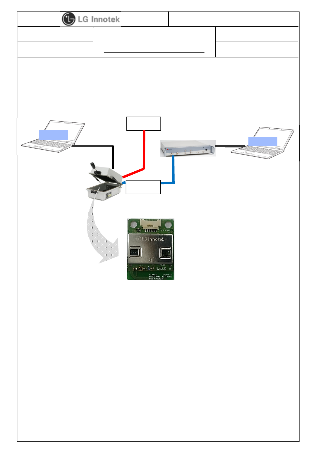
9. Test method
2) Test Set-up List.
- Instrument : LitePoint IQnxn or IQflex
- Shield Box : Tescom TC-5910DP
- RF Cable : TESCOM 4011-0011
- Attenuator : Mini-Circuit 15542 10dB attenuator
- USB Cable, LAN Cable, RF Cable
- Power Supply
3) Test Flow
- Install the test set-up.
- Power OFF.
- Open the Shield box and install the DUT for test.
- Close the shield box.
- Power ON.
- Check the driver icon.
- Start testing.
#. Notes.
- Be careful that you can consider a RF cable LOSS.
This is a conducted test method of Wi-Fi RF performance.
1) Test Condition.
7 / 9
S P E C I F I C A T I O N
PAGE :
DOCUMENT No. : -
REG. DATE : 2014.04.08
MODEL NAME : TWFM-M311D
REV. DATE : 2014.04.08
REV.NO : 1.00
©2014 LGIT. All rights reserved.
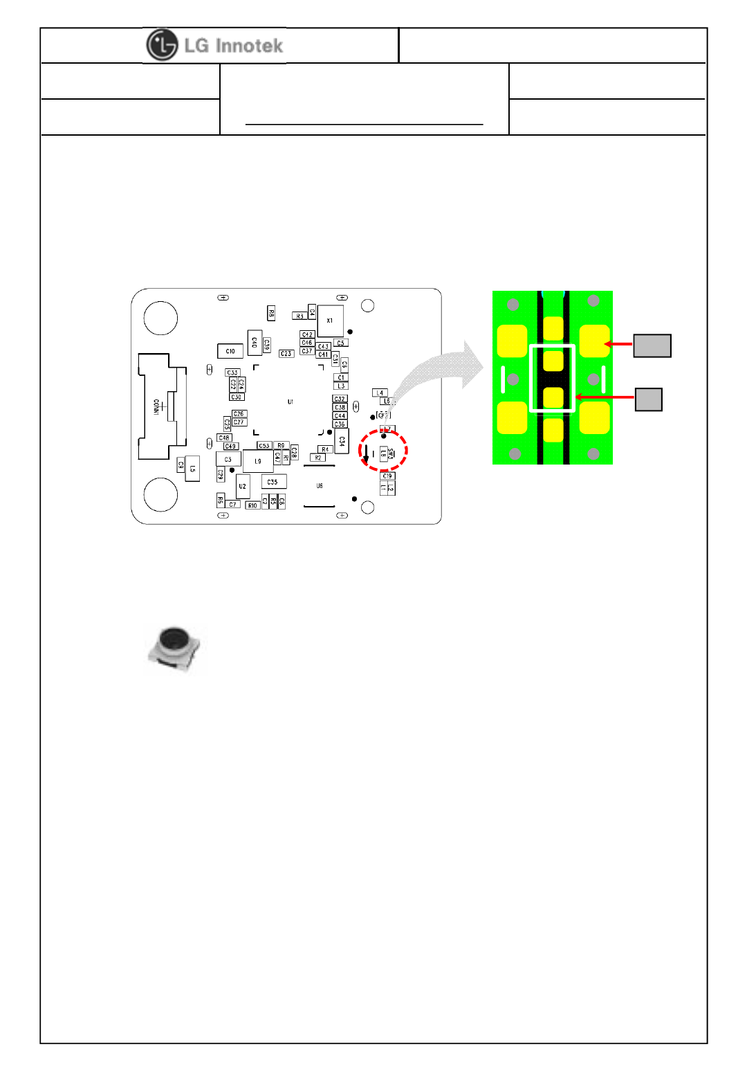
4) Test Method
(1) Remove the L8(L8 = 9pFH)
(2) Attach SW3(SW3 = MM8130-2600 )
(3) After all RF Test, remove SW3 and attach L8 (L8 = 9pF)
MM8130-2600
SW3
L8
< Top view >
8 / 9
S P E C I F I C A T I O N
PAGE :
DOCUMENT No. : -
REG. DATE : 2014.04.08
MODEL NAME : TWFM-M311D
REV. DATE : 2014.04.08
REV.NO : 1.00
©2014 LGIT. All rights reserved.
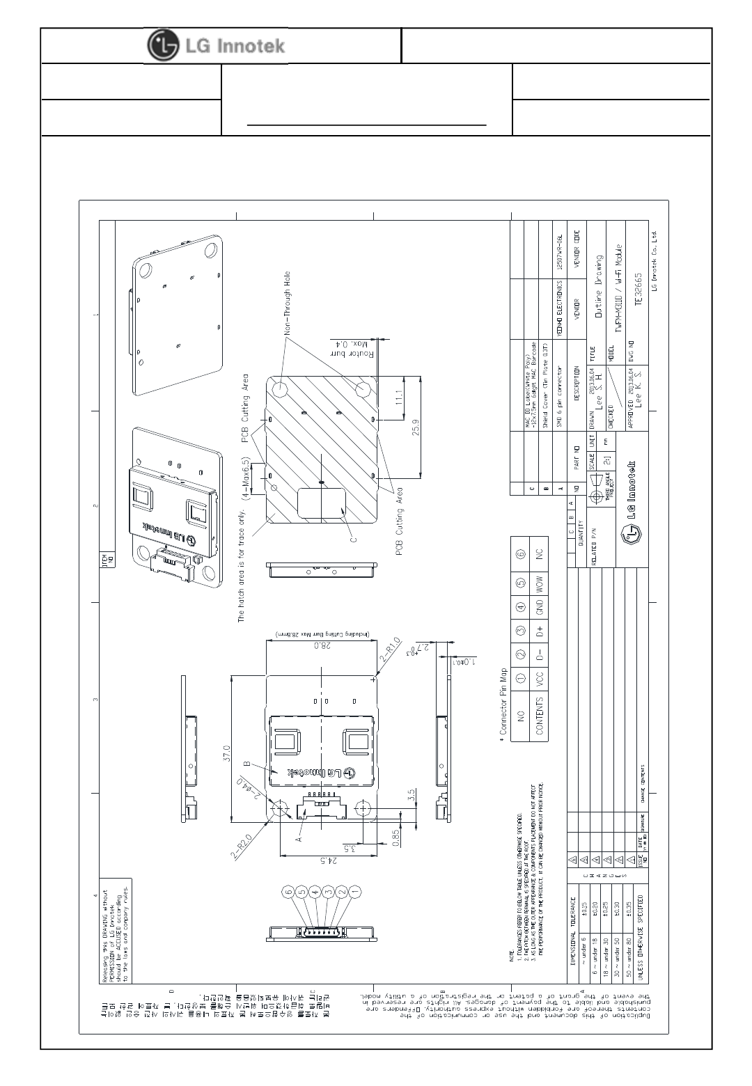
10. Outline Drawing
9 / 9

FCC Information
This device complies with part 15 of the FCC Results. Operation is subject to the
following two conditions :
(1) This device may not cause harmful interface, and
(2) This device must accept any interference received, including interference that
may cause undesired operation.
Note: This equipment has been tested and found to comply with the limits for CLASS B digital device,
pursuant to Part 15 of FCC Rules. These limits are designed to provide reasonable protection against harmful
interference when the equipment is operated in a commercial environment This equipment generates, uses
and can radiate radio frequency energy and, if not installed and used in accordance with the instructions,
may cause harmful interference to radio communications. However, there is no guarantee that interference
will not occur in a particular installation. If this equipment does cause harmful interference to radio or
television reception, which can be determined by turning the equipment off and on, the user is encouraged
to try correct the interference by one or more of the following measures:
1.1. Reorient or relocate the receiving antenna.
1.2. Increase the separation between the equipment and receiver.
1.3. Connect the equipment into an outlet on a circuit different from that to which receiver is connected.
1.4. Consult the dealer or experienced radio/TV technician for help.
WARNING
Changes or modifications not expressly approved by the manufacturer could void the
user’s authority to operate the equipment.
IC Information
This device complies with Industry Canada license-exempt RSS standard(s). Operation in subject to The
following two conditions: (1) this device may not cause interference, and (2) this device must accept any
interference, including interference that may cause undesired operation of the device.
Cet appareil est conforme avec Industrie Canada RSS standard exempts de licence(s), Son utilisation est
soumise à Les deux conditions suivantes: (1) cet appareil ne peut pas provoquer d’interférences et (2) cet
appareil doit accepter Toute interférence, y compris les interférences qui peuvent causer un mauvais
fonctionnement du dispositif.
Information for OEM Integrator
This device is intended only for OEM integrators under the following conditions:
1) The antenna must be installed such that 20 cm is maintained between the antenna and users, and
2) The transmitter module may not be co-located with any other transmitter or antenna.
End product labelling
The label for end product must include “Contains FCC ID: 2AB83-TWFM-M311D”.
“CAUTION : Exposure to Radio Frequency Radiation.
This equipment complies with FCC radiation exposure limits set forth for an uncontrolled environment. This
equipment must be installed and operated with minimum distance of 20cm between the radiator and your
body. This transmitter module is authorized only for use in device where the antenna may be installed such
that 20 cm may be maintained between the antenna and users.”