Sinocastel 213C OBD Vehicle Tracking Device User Manual
Sinocastel Co.,Ltd. OBD Vehicle Tracking Device
UserManual.wiki
>
Sinocastel
>
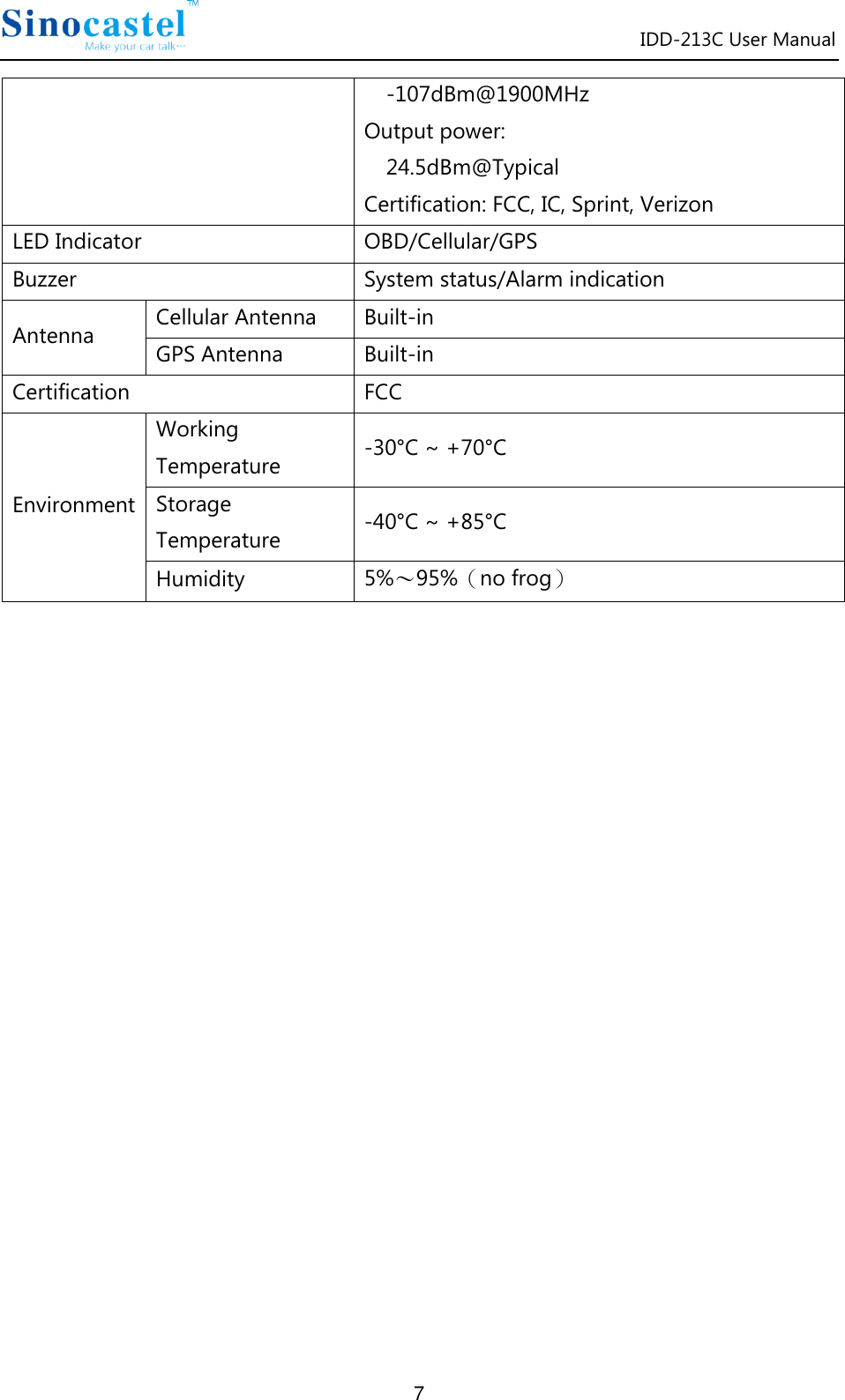
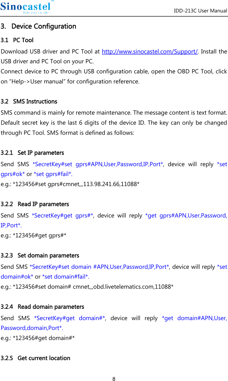
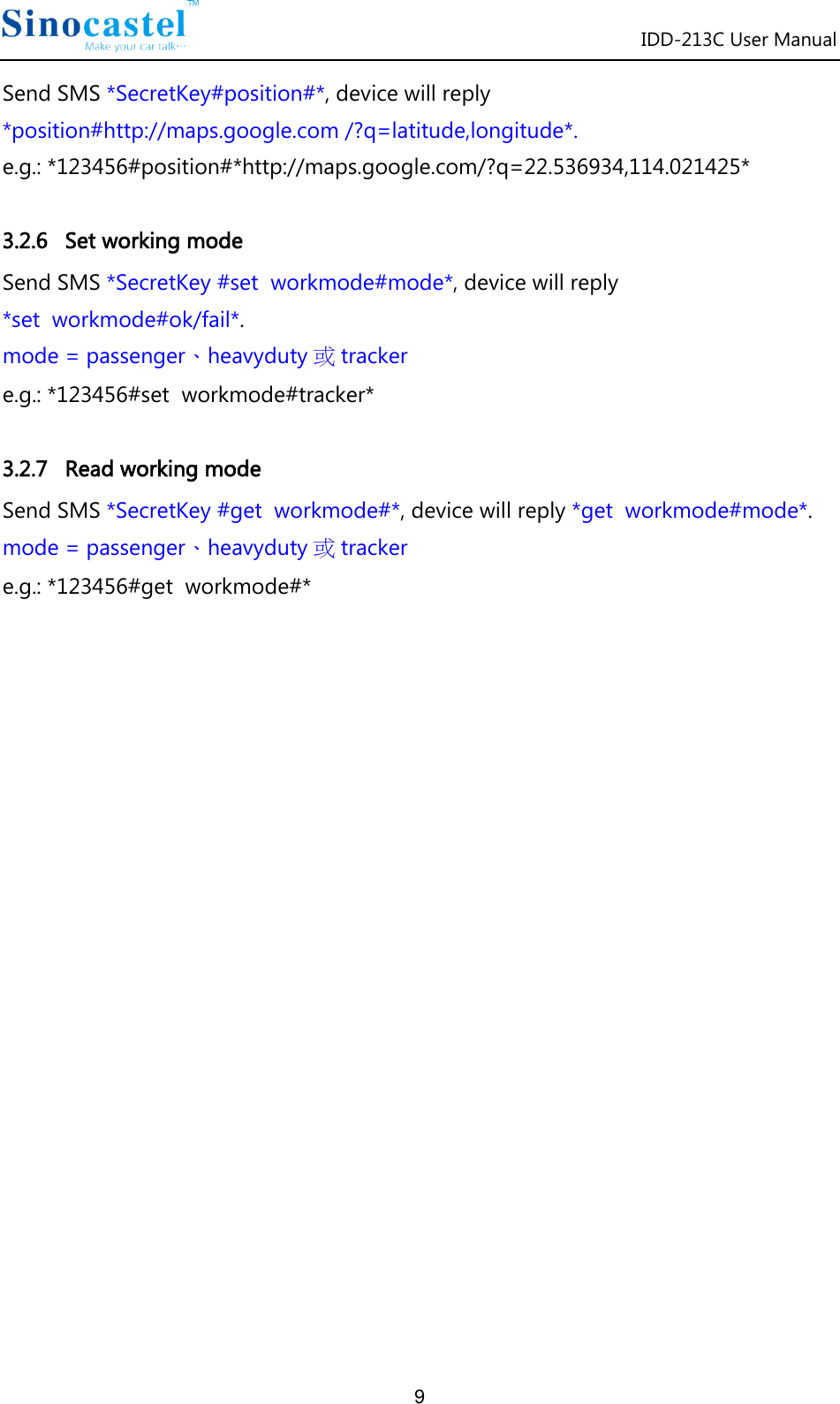
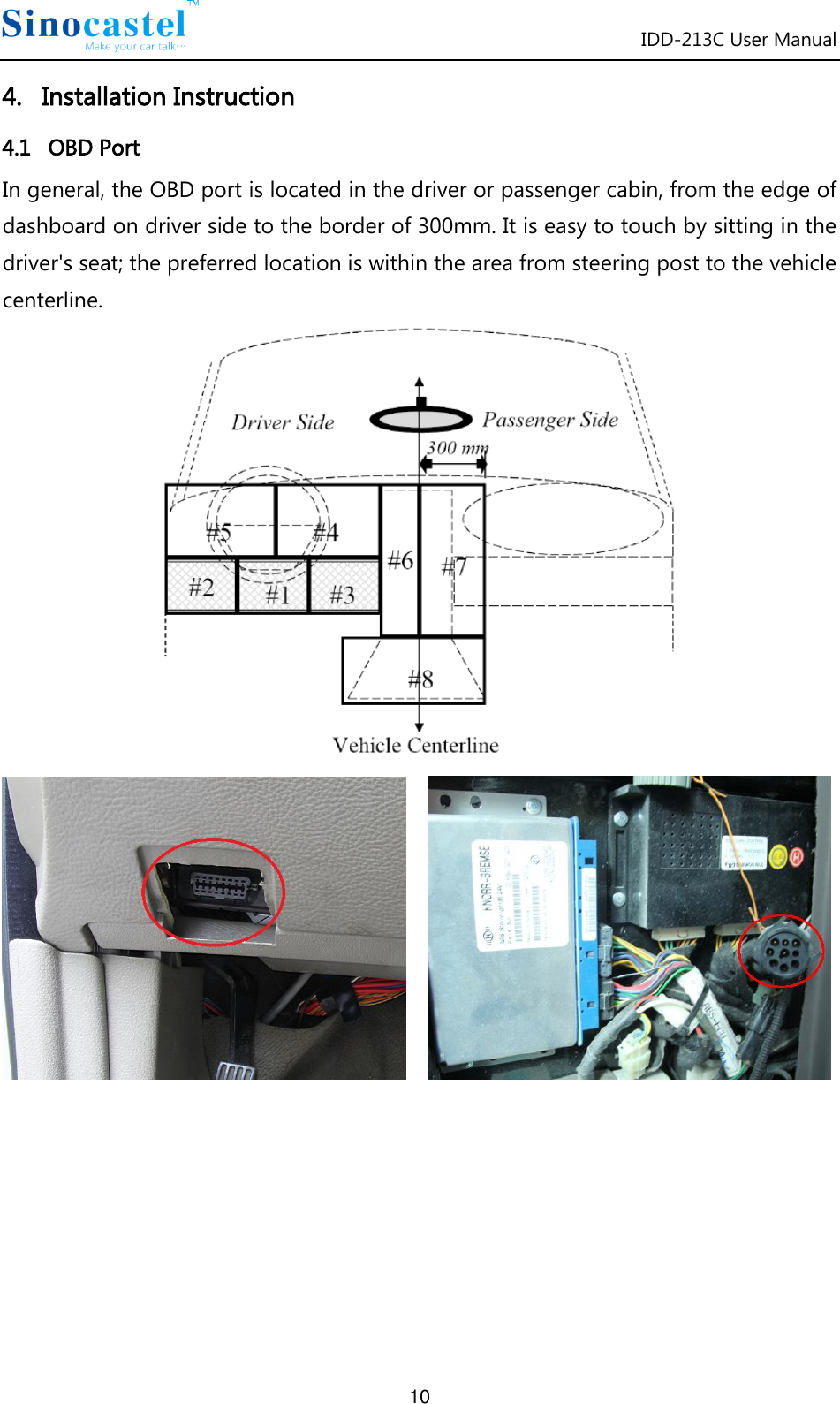
213C User Manual
User manual
Navigation menu
Upload a User Manual
Namespaces
Wiki Guide
HTML
PDF
Info
Views
User Manual
Discussion / Help
Navigation