Sinocastel 213N OBD GPS Tracker User Manual
Sinocastel Co.,Ltd. OBD GPS Tracker
User manual

IDD-213N User Manual
(Rev. 1.5)
Sinocastel Co., Ltd.
December, 2014

IDD-213N User Manual
1
Regulatory Compliance
FCC Regulations
This device complies with part 15 of the FCC Rules. Operation is subject to the
following two conditions: (1) This device may not cause harmful interference, and (2)
This device must accept any interference received, including interference that may
cause undesired operation.
This device has been tested and found to comply with the limits for a Class B digital
device, pursuant to Part 15 of the FCC Rules. These limits are designed to provide
reasonable protection against harmful interference in a residential installation. This
equipment generates, uses and can radiated radio frequency energy and, if not
installed and used in accordance with the instructions, may cause harmful interference
to radio communications. However, there is no guarantee that interference will not
occur in a particular installation If this equipment does cause harmful interference to
radio or television reception, which can be determined by turning the equipment off
and on, the user is encouraged to try to correct the interference by one or more of the
following measures:
-Reorient or relocate the receiving antenna.
-Increase the separation between the equipment and receiver.
-Connect the equipment into an outlet on a circuit different from that to which the
receiver is connected.
-Consult the dealer or an experienced radio/TV technician for help.
Caution: Changes or modifications not expressly approved by the party responsible
for compliance could void the user‘s authority to operate the equipment.
RF Exposure Information
This device complies with FCC radiation exposure limits set forth for an uncontrolled
environment. In order to avoid the possibility of exceeding the FCC radio frequency
exposure limits, human proximity to the antenna shall not be less than 20cm (8 inches)
during normal operation.

IDD-213N User Manual
1
Contents
1. Introduction ...................................................................................................................................................................... 3
2. Specifications ................................................................................................................................................................... 4
2.1 External Interface .................................................................................................................................................... 4
2.2 Status Indicator ....................................................................................................................................................... 5
2.3 Technical Parameters ............................................................................................................................................ 6
3. Device Configuration .................................................................................................................................................... 8
3.1 PC Tool ....................................................................................................................................................................... 8
3.2 SMS Instructions ..................................................................................................................................................... 8
4. Installation Instruction............................................................................................................................................... 10
4.1 SIM Card Installation .......................................................................................................................................... 10
4.2 OBD Port ................................................................................................................................................................. 11
4.3 Device Installation ............................................................................................................................................... 12
5. Functions ........................................................................................................................................................................ 16
5.1 OBD Protocols ...................................................................................................................................................... 16
5.2 Location Inquiry ................................................................................................................................................... 16
5.3 Regular GPS data reporting ............................................................................................................................ 16
5.4 Regular G-Sensor Data Reporting ................................................................................................................ 17
5.5 Regular Diagnostic Data Reporting .............................................................................................................. 17
5.6 DTCs Reporting .................................................................................................................................................... 17
5.7 Cell ID Reporting ................................................................................................................................................. 17
5.8 GPS Data Reporting in Sleep Mode ............................................................................................................. 18
5.9 Data storage/Supplementary Report in Dead zones ............................................................................. 18
5.10 Trip Mileage ........................................................................................................................................................ 18
5.11 Trip Fuel Consumption ................................................................................................................................... 18
5.12 Driving behavior monitoring ........................................................................................................................ 18
5.13 Alarms and Events Reporting ....................................................................................................................... 18
5.14 Working Mode ................................................................................................................................................... 19
5.15 GPS/Cellular Timer ............................................................................................................................................ 19
5.16 SMS Alert .............................................................................................................................................................. 19
5.17 Google Map Link ............................................................................................................................................... 20
5.18 Remote Configuration .................................................................................................................................... 20
5.19 SMS Configuration ........................................................................................................................................... 20
5.20 PC Tool Configuration ..................................................................................................................................... 20
6. Disclaimer ....................................................................................................................................................................... 21

IDD-213N User Manual
2
7. Warranty ......................................................................................................................................................................... 22
8. Statement ....................................................................................................................................................................... 23
IDD-213N User Manual
3
1. Introduction
IDD-213N is an intelligent on-board diagnostic device with OBD II and SAE
J1939/J1708 (Heavy duty) compliant, it features plug-and-play technology, could read
diagnostic info from vehicle ECU and capture location data with built-in GPS, then
send them to backend server for real-time remote diagnostic and tracking purpose.
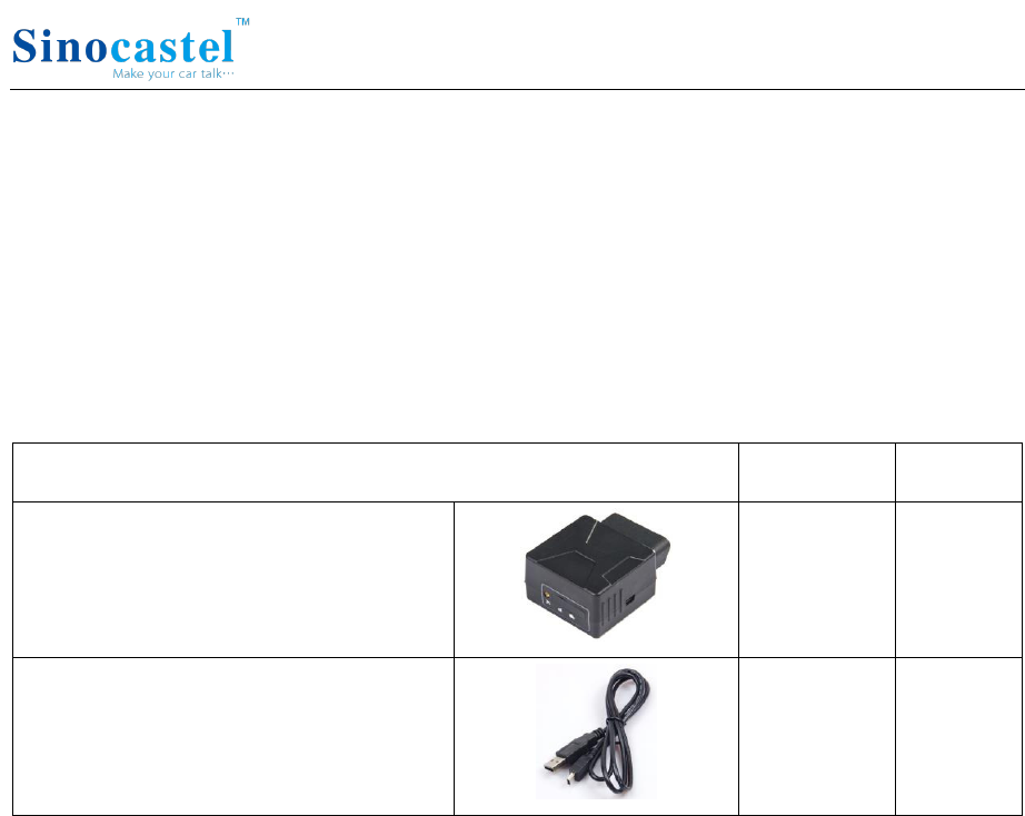
Packing List
Parts name
Quantity
Note
IDD-213N OBD Dongle
1
●
USB Configuration
Cable
1
○
Note: ● Standard configuration ○ Optional configuration
(Optional accessories will not be included if there is no indication in the order)
IDD-213N User Manual
4
2. Specifications
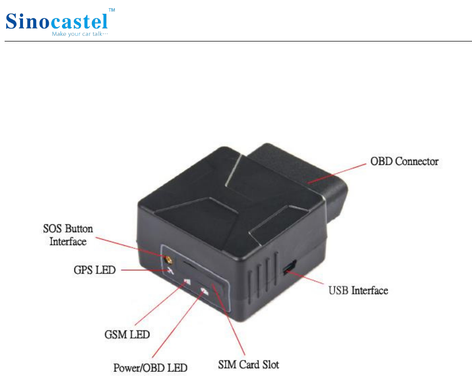
2.1 External Interface
Product appearance as follows:
1. Standard OBD Connector
Connect to the 16 pin on-board Diagnostic Link Connector (DLC).
2. Mini USB interface
Connect to PC through USB configuration cable.
3. SOS button Interface
This is a SOS button interface, to connect the SOS button for emergency, interface
type is MMCX.
4. SIM Card slot

IDD-213N User Manual
5
2.2 Status Indicator
Indicator
Color
Status
Power/OBD
LED
Red
Blinking (on 0.5s, off 0.5s) - Trying to access OBD
system or power off
Solid on - Successful OBD communication
Solid off - Tracker mode or in sleep
Cellular LED
Orange-red
Fast blinking (on 0.5s, off 0.5s) - No SIM card or
network searching
Slow blinking (on 0.5s, off 2.5s) - Registered network
Solid on - Logged into the server
Solid off - Cellular off
GPS LED
Green
Blinking (on 1s, off 1s) - GPS signal is good
Solid on - Searching for GPS signal
Solid off - GPS off
Buzzer
Beep
One beep - Power on
Two beeps - Successful OBD communication
Three beeps - Successful log in
Four beeps - Trip end and stop OBD communication
Five beeps - Power off
Six beeps - Fail to access OBD system
Five beeps (short beep) - Alarm indication

IDD-213N User Manual
6
2.3 Technical Parameters
Mechanical
Dimension
63mm (L) x 48mm (W) x 28mm (H)
Weight
50g
Interface
OBD interface: 16 pin standard OBD II
Configuration interface: Mini USB
SOS button interface: MMCX
SIM card interface: Push-Push Type
Storage
2MB FLASH, can store up to 24000 GPS data
Data Transmission
Packet data (GPRS or HSPA) and SMS
Positioning Mode
GPS
OBD Protocol
SAE J1850 PWM
SAE J1850 VPW
ISO 9141-2
ISO 14230-4
ISO 15765-4
SAE J1939 (Heavy duty)
SAE J1587/J1708 (Heavy duty)
Power
Working Voltage
9-36VDC
Working Currency
Average Currency: <150mA@13.8/27.6VDC
Max. Currency: <200mA@13.8/27.6VDC
Sleep Currency: <10mA@12/24VDC
Internal Battery
3.7V/160mA Lithium battery
3-axis Accelerometer
+/-2g、+/-4g、+/-8g、+/-16g
GPS
Channels: 48
Sensitivity: -163dBm
Accuracy: 5m CEP
Time to first fix:
Cold start: <35s (typ.)
Hot start: <1s (typ.)
Cellular
Frequency:
GSM/GPRS/EDGE: 850/1900MHz
UMTS/HSDPA: 850/1900MHz
Network protocol: Embedded TCP/IP stack
Sensitivity:

IDD-213N User Manual
7
-111dBm@UMTS
-109dBm@GSM 850MHz
-110dBm@GSM 1900MHz
Certification: FCC, PTCRB, IC
LED Indicator
OBD/Cellular/GPS
Buzzer
System status/Alarm indication
Antenna
Cellular Antenna
Built-in
GPS Antenna
Built-in
Environment
Working
Temperature
-30℃ ~ +70℃
Storage
Temperature
-40℃ ~ +85℃
Humidity
5%~95%no frog

IDD-213N User Manual
8
3. Device Configuration
3.1 PC Tool
Download USB driver and PC Tool at http://www.sinocastel.com/en/Downloads/.
Install the USB driver and PC Tool on your PC.
Connect device to PC through USB configuration cable, open the OBD PC Tool, click
on “Help->User manual” for configuration reference.
3.2 SMS Instructions
SMS command is mainly for remote maintenance. The message content is text format.
Default secret key is the last 6 digits of the device ID. The key can only be changed
through PC Tool. SMS format is defined as follows:
3.2.1 Set IP parameters
Send SMS *SecretKey#set gprs#APN,User,Password,IP,Port*, device will reply *set
gprs#ok* or *set gprs#fail*.
e.g.: *123456#set gprs#cmnet,,,113.98.241.66,11088*
3.2.2 Read IP parameters
Send SMS *SecretKey#get gprs#*, device will reply *get gprs#APN,User,Password,
IP,Port*.
e.g.: *123456#get gprs#*
3.2.3 Set domain parameters
Send SMS *SecretKey#set domain #APN,User,Password,IP,Port*, device will reply *set
domain#ok* or *set domain#fail*.
e.g.: *123456#set domain# cmnet,,,obd.livetelematics.com,11088*
3.2.4 Read domain parameters
Send SMS *SecretKey#get domain#*, device will reply *get domain#APN,User,
Password,domain,Port*.
e.g.: *123456#get domain#*

IDD-213N User Manual
9
3.2.5 Get current location
Send SMS *SecretKey#position#*, device will reply
*position#http://maps.google.com /?q=latitude,longitude*.
e.g.: *123456#position#*http://maps.google.com/?q=22.536934,114.021425*
3.2.6 Set working mode
Send SMS *SecretKey #set workmode#mode*, device will reply
*set workmode#ok/fail*.
mode = passenger、heavyduty 或tracker
e.g.: *123456#set workmode#tracker*
3.2.7 Read working mode
Send SMS *SecretKey #get workmode#*, device will reply *get workmode#mode*.
mode = passenger、heavyduty 或tracker
e.g.: *123456#get workmode#*
IDD-213N User Manual
10
4. Installation Instruction
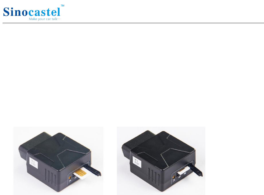
4.1 SIM Card Installation
1. Remove the SIM card cover.
2. Insert the SIM card and press gently, a click will be heard upon successfully placing
the SIM card in its place, please follow the insertion direction marked on the SIM
card cover.
3. Put the SIM card cover back.
Note:
There is a backup battery in the device, please make sure all lights are off before inserting or
removing SIM card.
IDD-213N User Manual
11
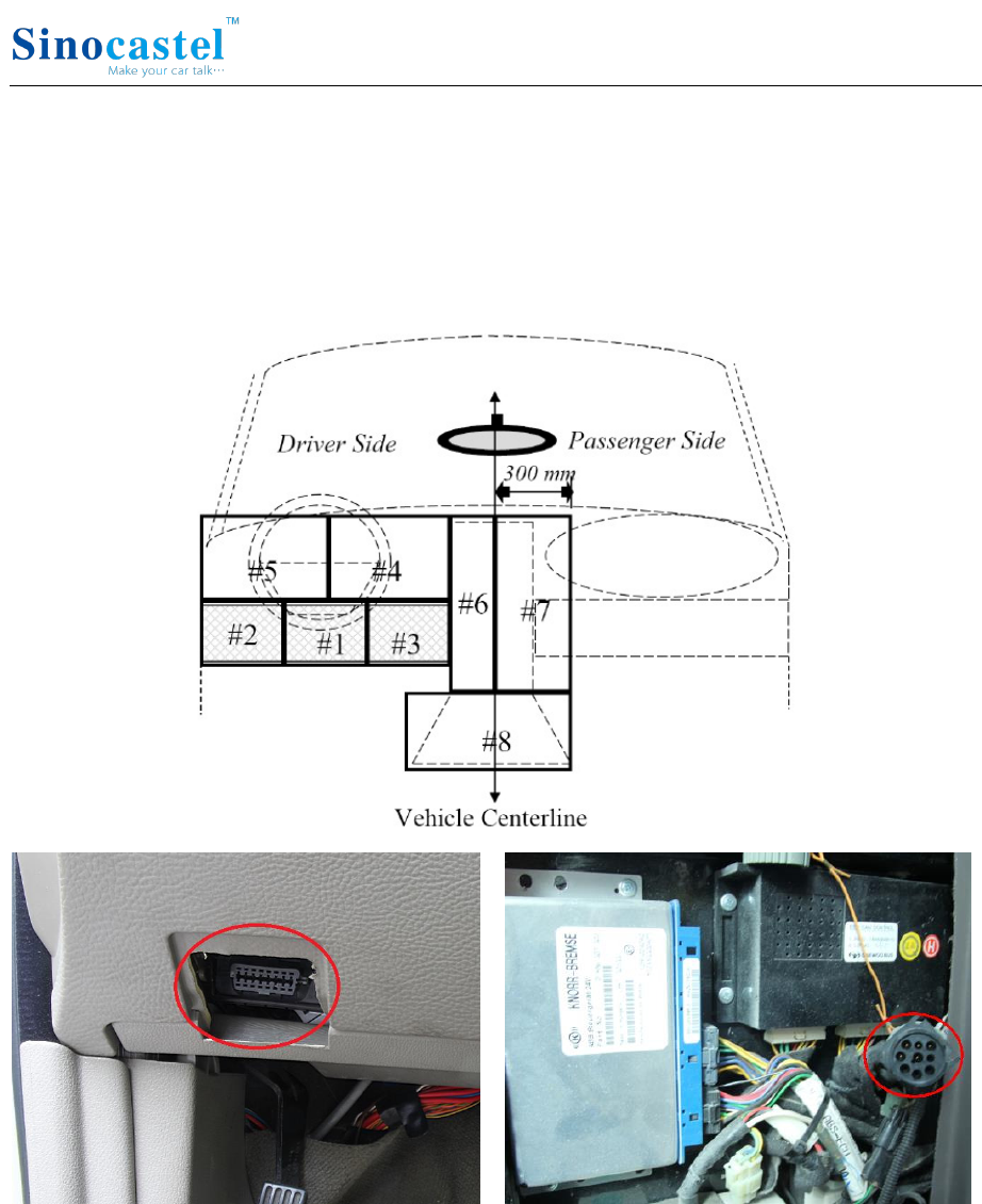
4.2 OBD Port
In general, the OBD port is located in the driver or passenger cabin, from the edge of
dashboard on driver side to the border of 300mm. It is easy to touch by sitting in the
driver's seat; the preferred location is within the area from steering post to the vehicle
centerline.
IDD-213N User Manual
12
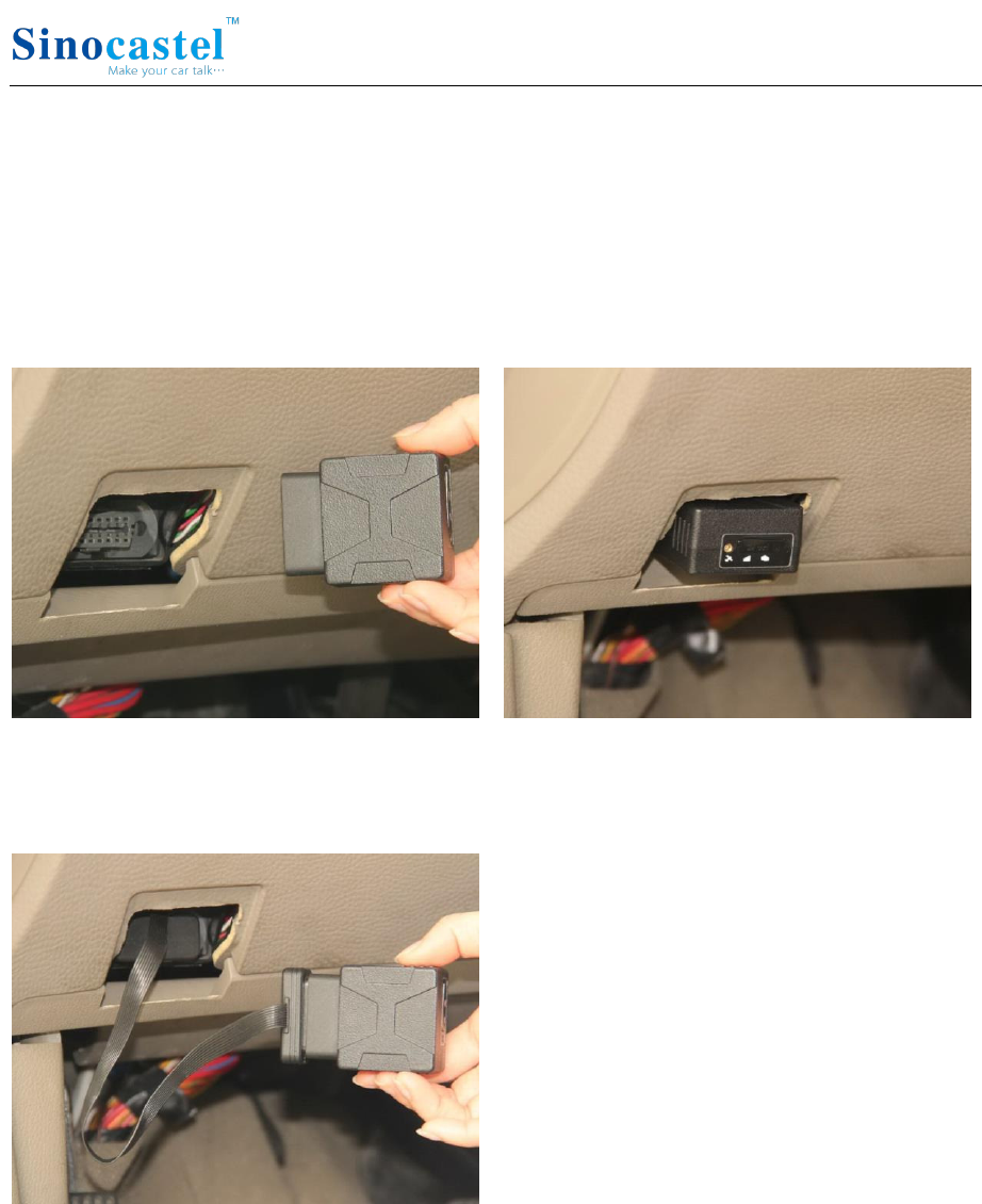
4.3 Device Installation
Before installing the device, please make sure device has been configured with
necessary parameters including network parameters and working mode.
Park the car and make sure engine is off, align the OBD connector of the device with
the engine diagnostic port and simply push in place, ensuring the device is secure.
There comes one beep indicating device is power on.
If the OBD port cover can not be closed back after device plugged in, please use OBD
extension cable and mount the device in proper place.
IDD-213N User Manual
13
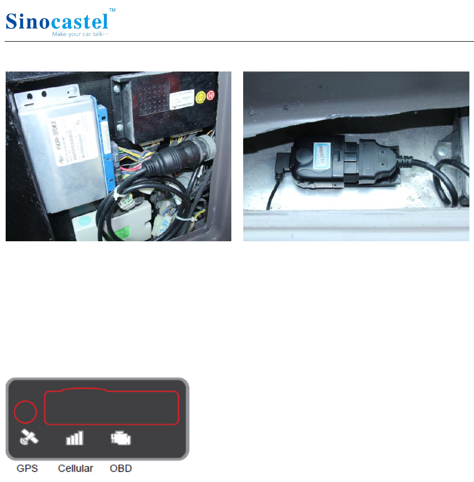
Some heavy duties may need 9-Pin or 6-Pin deutsch wiring harness.
For vehicles do not have an OBD port, please use power cable to connect vehicle
battery and configure the device with tracker mode.
Start engine, then device starts OBD communication, acquiring GPS info and Cellular
network connection. Various status can be indicated by lights and beeps.
OBD communication: The OBD light change its status to solid on and comes 2 beeps
with successful OBD communication.
GPS function: The GPS light becomes blinking indicates that device has got its
location.
Cellular connection: The Cellular light change its status to slow blinking indicates
registered network, becomes solid on and comes 3 beeps indicate logged into the
server.
Note:
*Firmware below V2.2.2: When working with passenger or heavy duty mode, if OBD light keeps
blinking and comes 6 beeps it means that device is not compatible with the vehicle, please change
working mode. If it does not work with both passenger and heavy duty modes please change to
tracker mode. To change working mode: 1) Remove the device, configure with PC Tool and install
again. Or, 2) Send SMS *secretkey#set workmode#mode*, secretkey is the last 6 digits of device ID
IDD-213N User Manual
14
as default, mode can be passenger or heavyduty or tracker, device will reboot and work with
configured working mode. SMS should be sent within 10 minutes after device plugged in, or it will
go into sleep. With tracker mode, diagnostic functions are not provided, device simply gets power
from OBD port. When plugged in there comes 6 beeps indicating it is working with tracker mode,
if engine keeps off or idle state device will go into sleep after 3 minutes.
*Firmware V2.2.2 and above: When device is the first time power on (plugged in), it will scan OBD
protocol according to pre-configured working mode (ie, passenger car or heavy duty mode), the
maximum scanning time can be up to 10 minutes, if no OBD protocol is detected during this
period, device will auto change working mode to tracker mode, if OBD protocol is detected, device
will keep its working mode. After auto scanning period device will not change working mode
anymore even it is re-plugged, unless working mode is re-configured with PC Tool, via SMS, or
from server. If tracker mode is pre-configured device will not scan OBD protocol and keep working
with tracker mode unless working mode is re-configured. There comes 6 beeps indicating that
device is working with tracker mode.
*If GPS does not work, please use OBD extension cable and mount the device in a proper place to
make sure GPS signal can be well received.
*If dashboard lights are abnormal after installation, please remove the device and contact
Sinocastel technical team.
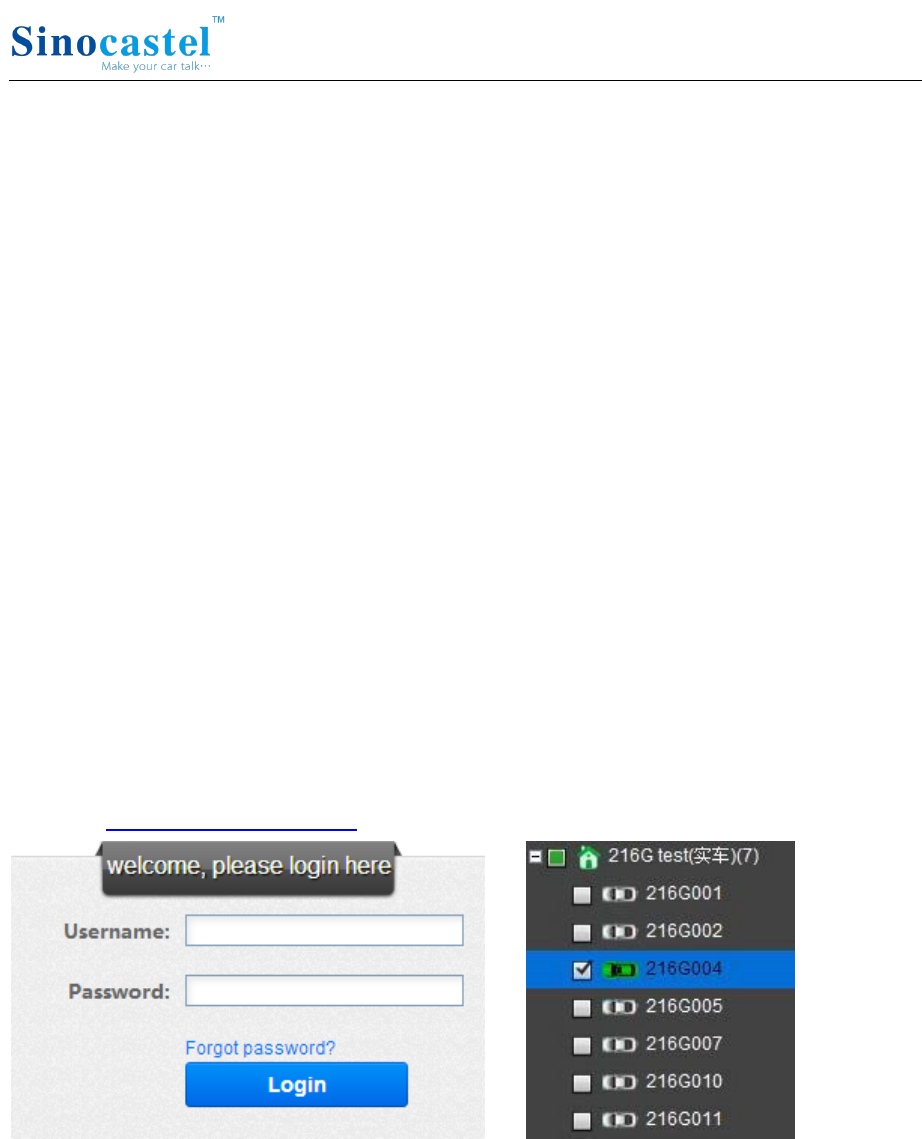
Log into www.livetelematics.com to check real-time monitor and trip reports.
Login Vehicle monitoring list
IDD-213N User Manual
15
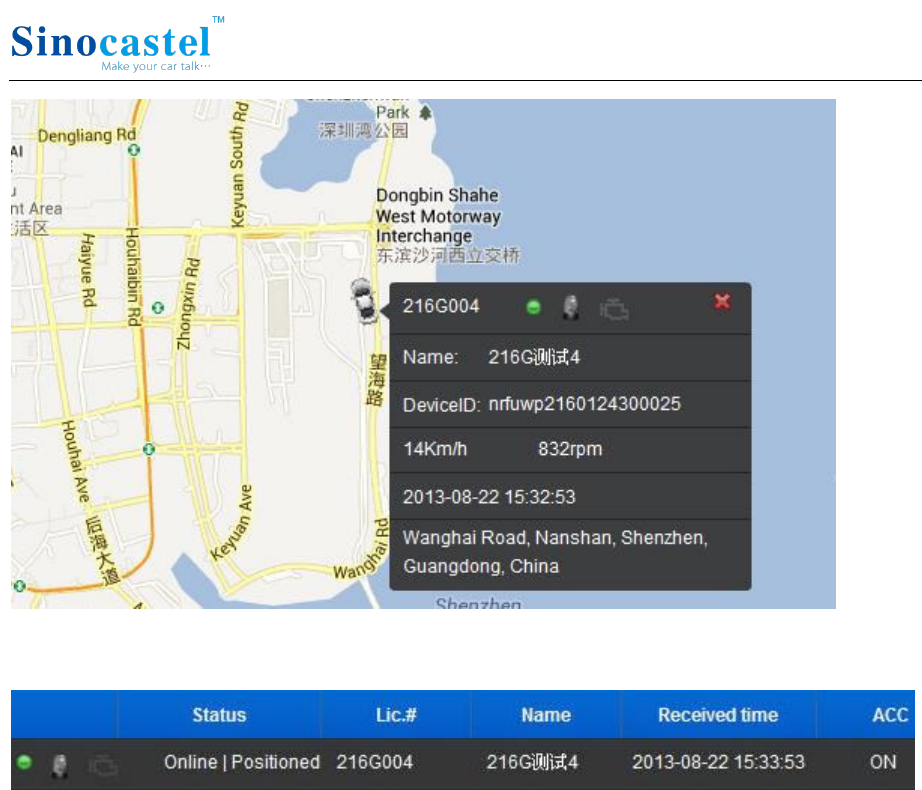
Vehicle real time location
Vehicle real time status

IDD-213N User Manual
16
5. Functions
5.1 OBD Protocols
Device supports all legislated OBD II protocols, it is also SAE J1939 and SAE J1708
compliant.
SAE J1850-PWM
SAE J1850-VPW
ISO 9141-2
ISO 14230-4 (KWP2000)
ISO 15765-4 (CAN)
SAE J1939 (Heavy duty)
SAE J1587/J1708 (Heavy duty)
5.2 Location Inquiry
Upon receiving location inquiry message from server or via SMS, device reports GPS
data immediately.
5.3 Regular GPS data reporting
GPS data can be sampled by 3 means: by time interval, by distance or by heading
change. They can be enabled or disabled separately, only sampled by time interval is
enabled by default.
The sample rate for time interval can be 2-600s and default setting is 30s, for distance
interval can be 50-5000m and default setting is 500m, for heading change can be
5-90° and default setting is 15°.
There can be single or several groups of GPS data in one GPS message, determined by
groups of GPS data per message, device will not report GPS message until it has
collected specified groups of GPS data. Groups of GPS data per message can be 1-30
and default setting is 1.
For example, sampled by time interval and sampled by distance are enabled, and the
respective settings are 10s and 500m, groups of GPS data per message is 5. Assume
that vehicle is running at speed of 72km/h (20m/s), then it takes 25s to run out of
500m, so GPS data are sampled at 10th, 20th, 25th, 30th, 40th second and reported at
40th second as 5 groups of GPS data have been collected at that time.

IDD-213N User Manual
17
The suggested minimal interval for GPS report is 10s. For example, if only sampled by
time interval is enabled, then the settings might be 10s of sample rate and 1 group of
GPS data per message, or 5s of sample rate and 2 groups of GPS data per message.
5.4 Regular G-Sensor Data Reporting
Device reports G-Sensor data (g-value of X/Y/Z axis) according to configured time
interval, this function is disabled by default.
The sample rate can be 200-6000ms and default setting is 1000ms.
There can be single or several groups of G-Sensor data in one G-Sensor message,
determined by groups of G-Sensor data per message, device will not report G-Sensor
message until it has collected specified groups of G-Sensor data. Groups of G-Sensor
data per message can be 50-100 and default setting is 100.
5.5 Regular Diagnostic Data Reporting
Device is able to read variety of vehicle diagnostic data, also called PID (parameter ID),
including vehicle speed, engine RPM, engine coolant temperature, mass flow air, etc,
and report up to 10 types of PID data according to configured time interval.
The sample rate can be 2-600s and default setting is 60s.
There can be single or several groups of PID data in one PID message, determined by
groups of PID data per message, device will not report PID message until it has
collected specified groups of PID data. Groups of PID data per message can be 1-30
and default setting is 1.
The suggested minimal interval for PID report is 10s, for example, 10s of sample rate
and 1 group of PID data per message, or 5s of sample rate and 2 groups of PID data
per message.
5.6 DTCs Reporting
Device is able to read vehicle pending and stored DTCs (diagnostic trouble code), and
freeze frame data. The backend server analyzes and displays the DTCs for users on
time to avoid high repairing cost.
5.7 Cell ID Reporting
Device reports Cell ID every 30 seconds when it loses GPS signal, this function is
disabled by default.

IDD-213N User Manual
18
5.8 GPS Data Reporting in Sleep Mode
Device reports GPS data according to configured time interval during sleep. The time
interval can be 10-1440min and default setting is 60min.
5.9 Data storage/Supplementary Report in Dead zones
When there is no Cellular signal or Cellular signal is poor, GPS information are stored,
and reported after signal recovery. Supplementary report can be last for 15 minutes at
most after ignition is off.
5.10 Trip Mileage
Device reports driving mileage in each reported message.
5.11 Trip Fuel Consumption
Device reports fuel consumption in each reported message.
5.12 Driving behavior monitoring
Real-time detects bad driving behavior, including Speeding, high RPM, hard
acceleration, hard brake, excessive engine idle time.
5.13 Alarms and Events Reporting
Alarms and Events are reported when they are triggered or eliminated and there
comes short beeps, beeps are disabled by default.
Engine on/off (Supported from firmware V2.1.2)
High RPM (triggered and eliminated)
Speeding (triggered and eliminated)
Low battery voltage (triggered and eliminated)
High engine coolant temperature (triggered and eliminated)
Hard acceleration
Hard brake
Excessive engine idle time (triggered and eliminated)
Fatigue driving (triggered and eliminated)
Towed
MIL on/off (Supported from firmware V2.1.2)
Excessive exhaust emission (triggered and eliminated)

IDD-213N User Manual
19
Plug indication
Unplug notification
Emergency
Default thresholds for alarms:
High RPM: 4500r/min
Speeding: 120km/h
Low battery voltage: 10.5V
High engine coolant temperature: 98℃
Hard acceleration: 0.4g
Hard brake: 0.6g
Excessive engine idle time: 15min
Fatigue driving: 240min
5.14 Working Mode
Device supports 3 types of working mode: Passenger car, Heavy duty and Tracker
mode.
With tracker mode, device does not report diagnostic data, DTCs, trip fuel
consumption and some alarms including high RPM, high engine coolant temperature,
hard acceleration, hard brake, excessive engine idle time, MIL and excessive exhaust
emission.
With Tracker mode, device wakes up from sleep on detecting motion state last for 20
seconds, and goes into sleep on detecting static state last for 3 minutes.
5.15 GPS/Cellular Timer
GPS and cellular can keep working after ignition off according to configured timer, but
no regular reports during this period. This function is disabled by default. (Supported
from firmware V2.1.2)
The timer for GPS/GSM can be 5-7200min and default setting is 720min, for data
connection can be 5-120min and default setting is 60min.
5.16 SMS Alert
If user mobile phone numbers are configured, device sends SMS to each user number
when alarms are triggered or eliminated, it is disabled by default.

IDD-213N User Manual
20
5.17 Google Map Link
Latitude and longitude in location SMS can be directly linked to Google map.
5.18 Remote Configuration
Users can configure device or update firmware through website:
http://www.livetelematics.com.
5.19 SMS Configuration
Users can configure device via SMS commands.
5.20 PC Tool Configuration
Users can configure device or update firmware through PC Tool.

IDD-213N User Manual
21
6. Disclaimer
This user manual only applies to IDD-213N device.
The device is compatible with OBD II standard, it is also SAE J1939 and J1708
compliant. While some vehicles are not following those standards, therefore
Sinocastel can not guarantee the OBD performance of the device with every vehicle.
The GPS function may be affected in electromagnetic shielding area or bunker place.
The device has a built-in cellular module. It should be used as far as possible away
from fuel depots, chemical plants and other areas could cause an explosion. Most
sensitive to external RF sites (such as gas stations, hospitals and school, etc.) may be
equipped with radio frequency jamming equipment; some functions may be affected
in the interference area.
As the device transmits data via cellular, please use the SIM card which supports data
service and make sure that the account balances is sufficient. Do not use any SIM card
which is restricted by region.
To make sure the products works well, please use the original accessories.
This manual is based on the “as-is” situation. Sinocastel will not guarantee the
accuracy, reliability and content of the handbook. Also Sinocastel reserves the right to
amend or withdrawn this manual without any prior notification.

IDD-213N User Manual
22
7. Warranty
If product got quality problem within the warranty period, please bring the product
together with a valid warranty card and purchase invoice to the dealer for checking.
Please do not disassemble this product, this may result in damage, Sinocastel will not
be responsible for those problem.
1 year of warranty since purchase time and life-long maintenance. For Failure or
damage due to incorrect operation or not following the instruction, Sinocastel will
provide paid maintenance within warranty period.
User name:
Contact number:
Address:
Post code:
Purchasing date:
Serial number:
Remark:
Please keep this card carefully in order to better serve you.
Distributor (Company Chop):
Maintenance Records
Product Model:
Date
Faults and maintenance of records
Maintenance
(Signature)
User
(Signature)
Fault Description
Maintenance
Note: This form must be carefully completed.

IDD-213N User Manual
23
8. Statement
Without written permission from Sinocastel, it is prohibited reproduce, transmit,
distribute or save part or all of the contents of this document in any form.
Sinocastel reserves the rights to modify or improve these products without any prior
notification.
Sinocastel reserves the rights to change or cancel the content of this document
without any prior notification.
All rights reserved by Sinocastel Co., Ltd.
Address: 5/F, 5th Building, Software Park, No. 2 Gaoxin C. 3rd Road, Nanshan,
Shenzhen, China
Postcode: 518057
Tel: (86)755-86156349
Fax: (86)755-86169366
http://www.sinocastel.com