Skidata ASX70IKEY Transponder-card reader for access control User Manual Cover ASx70iDUO 1 0 en
Skidata AG Transponder-card reader for access control Cover ASx70iDUO 1 0 en
UserManual.wiki
>
Skidata
>
ASX70IKEY User Manual
User manual
Navigation menu
Upload a User Manual
Namespaces
Wiki Guide
HTML
PDF
Info
Views
User Manual
Discussion / Help
Navigation

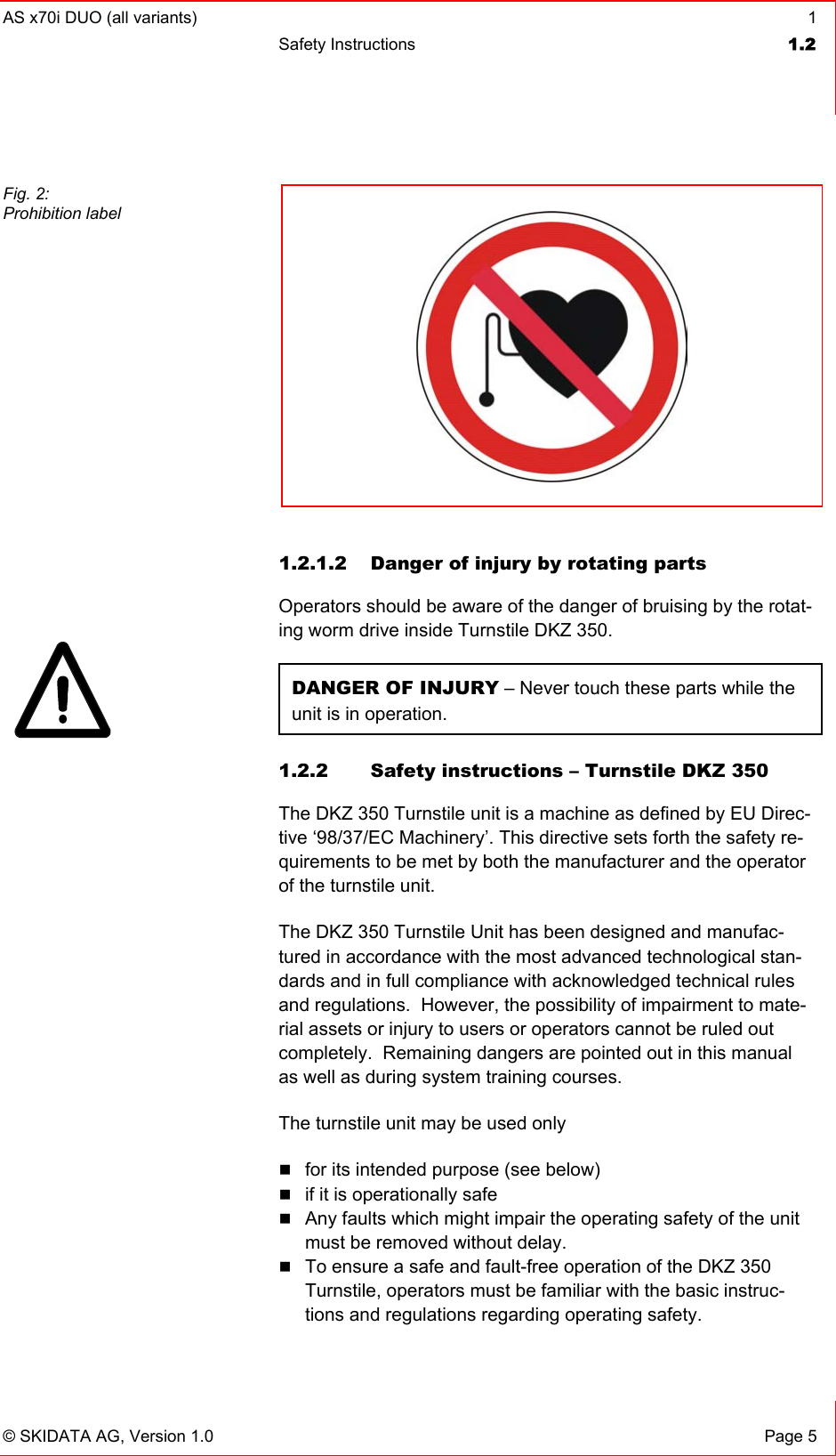
![1 AS x70i DUO (all variants) 1.2 Safety Instructions Page 4 © SKIDATA AG, Version 1.0 Persons affected by these guidelines (e.g. pacemaker wear-ers) are not allowed to place keycards or other contactless (electronic) access control data carriers next to the implant when passing an access device. When passing through an access gate, a minimum distance of 30 cm should be kept between the antenna and the implant (to ensure this minimum distance, the use of a Swatch Access watch or Gore [s-key] gloves is recommended). Wearers of medical implants such as pacemakers should avoid leaning against an antenna unit. For wearers of medical implants such as pacemakers, the time of exposure to the RF scanning signal should be as short as possible when passing through the gate at normal speed; when queuing, they should stand at an appropriate distance from RF-based devices. Persons experiencing problems such as dizziness or nausea when passing an antenna should leave the scanning range of the device immediately. Antennas must bear a warning label or prohibit label (shown in figures below), which must be readily visible to wearers of medi-cal devices. In addition, a warning sign with the above-mentioned safety guidelines should be placed at every point of initial access (e.g. cash desks). Also, lift staff should receive appropriate instructions to be able to provide information and assistance if and when required. Fig. 1: Warning label](https://usermanual.wiki/Skidata/ASX70IKEY/User-Guide-401125-Page-8.png)