Skidata RDKEY RFID Reader User Manual
Skidata AG RFID Reader
UserManual.wiki
>
Skidata
>
RDKEY User Manual
user manual
Navigation menu
Upload a User Manual
Namespaces
Wiki Guide
HTML
PDF
Info
Views
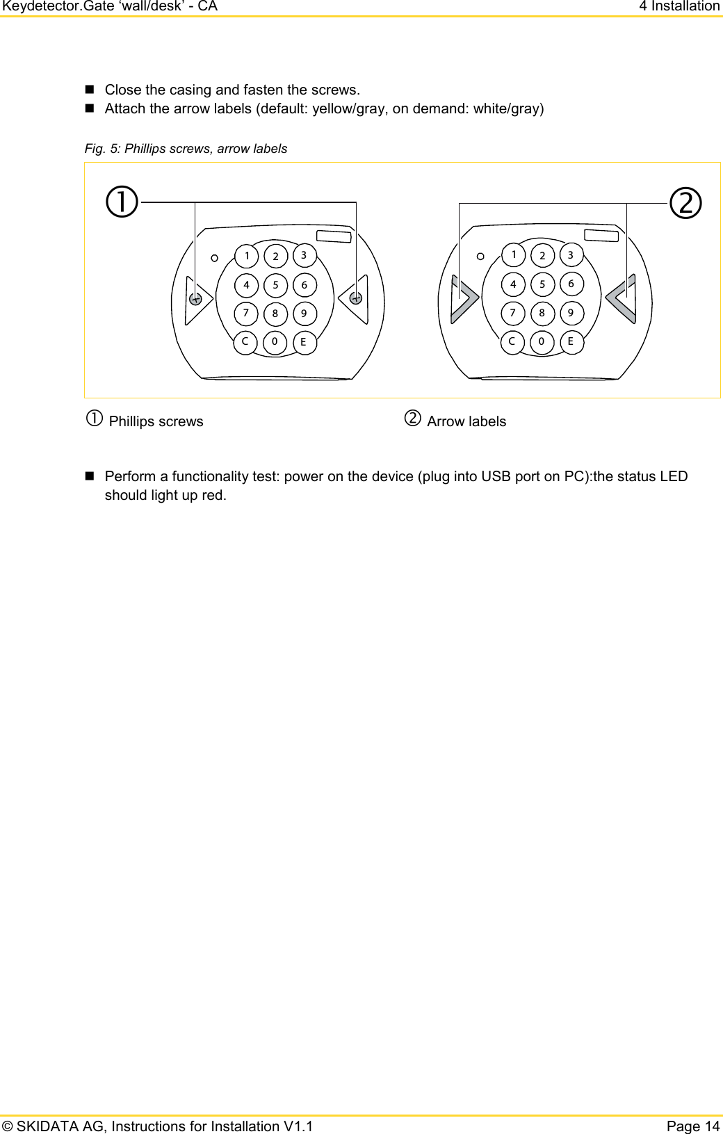
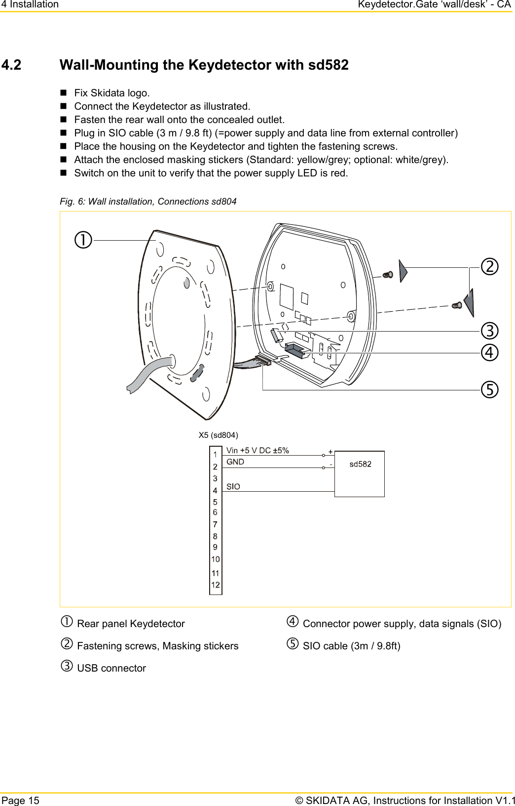
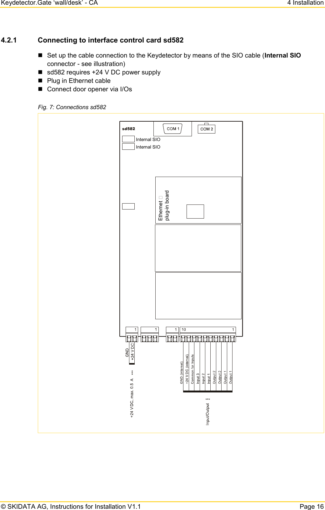
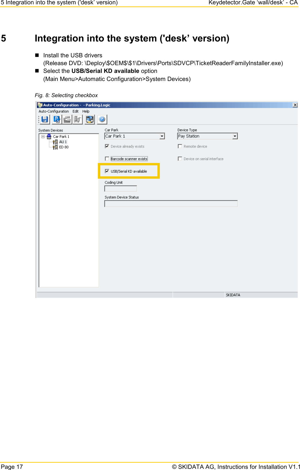
User Manual
Discussion / Help
Navigation