Skoda Octavia Tour Owners Manual ManualsLib Makes It Easy To Find Manuals Online!
2014-12-11
: Skoda Skoda-Octavia-Tour-Owners-Manual-121420 skoda-octavia-tour-owners-manual-121420 skoda pdf
Open the PDF directly: View PDF ![]() .
.
Page Count: 224 [warning: Documents this large are best viewed by clicking the View PDF Link!]
SIMPLY CLEVER
How you can contribute to a cleaner environment
The fuel consumption of your Škoda - and thus the level of
pollutants contained in the exhaust - is also determined by
how you drive.
The noise level and wear and tear are also influenced by how
you personally handle your vehicle. This Owner ´s Manual tells
you how to drive your Škoda to achieve the minimum impact
on the environment, and how to save money at the same time.
Look up „Environment“ in the Index to find out more.
Please also refer to all the texts identified with a in this
Owner ´s Manual.
Make your contribution - for the sake of the
environment.
www.skoda-auto.com
Návod k obsluze
Octavia Tour anglicky 05.09
S63.5610.34.20
1U0 012 003 KT
Octavia Tour anglicky 05.09 S63.5610.34.20
ŠkodaOctavia Tour
OWNER‘S MANUAL
Introduction
You have opted for a Škoda - our sincere thanks for your confidence in us.
Your new Škoda offers you a vehicle featuring the most modern engineering and a wide range of equipment which
you will undoubtedly wish to use to the full during your daily motoring. That is why, we recommend that you read
this Owner's Manual attentively to enable you to become familiar with your car and all that it offers as quickly as
possible.
Please do not hesitate to contact your specialist garage or importer should you have any further questions or any
problems regarding your vehicle which may arise. He will be ready at any time to receive your questions, sugges-
tions and criticisms.
National legal provisions, which deviate from the information contained in these operating instructions, take prec-
edence over the information contained in the operating instructions.
We wish you much pleasure with your Škoda and pleasant motoring at all times.
Your Škoda Auto
s2g8.b.book Page 1 Tuesday, April 7, 2009 8:53 AM

Introduction2
On-board literature
The on-board literature for your vehicle consists of this “Owner's
Manual” as well as the “Quick Reference Guide”, “Service Schedule”
and “Help on the road”. There can also be a variety of other additional
operating manuals and instructions on-board (e.g. an operating manual
for the radio) depending on the vehicle model and equipment.
If one of the publications listed above is missing, please contact a
specialist garage immediately, where one will be glad to assist you in such
matters.
One should note that the details given in the vehicle's papers always
take precedence over those in the Owner's Manual.
Owner's Manual
This Owner's Manual describes the current scope of equipment.
Certain items of equipment listed are only installed later on and only
envisaged for particular markets. The illustrations can differ in minor
details from your vehicle; they are only intended for general information.
In addition to information regarding all the controls and equipment, the
Owner's Manual also contains important information regarding care and
operation for your safety and also to retain the value of your vehicle. To
provide you with valuable tips and aids. You will learn how you can
operate your vehicle safely, economically and in an environmentally
conscious way.
For safety reasons, please also pay attention to the information on
accessories, modifications and replacement of parts ⇒page 179.
The other chapters of the Owner's Manual are also important, however,
for proper treatment of your car - in addition to regular care and mainte-
nance - helps to retain its value and in many cases is also one of the
conditions for possible warranty claims.
The Service schedule
contains:
•Vehicle data;
•Service intervals;
•Overview of the service work;
•Service proof;
•Confirmation of mobility warranty;
•important information on the warranty.
The confirmations of the carried out service work are one of the condi-
tions for possible warranty claims.
Please always present the Service schedule when you take your car to a
specialist garage.
If the Service schedule is missing or worn, please contact the specialist
garage where your car is serviced regularly. You will receive a duplicate, in
which the previously carried out service work are confirmed.
Help on the road
contains the addresses and telephone numbers of Škoda Importers.
s2g8.b.book Page 2 Tuesday, April 7, 2009 8:53 AM

Contents 3
riving Tips General Maintenance Breakdown assistance Technical Data
Contents
Layout of this Owner's Manual
(explanations) . . . . . . . . . . . . . . . . . . . . . . . . . .
Using the system . . . . . . . . . . . . . . . . . . . . . .
Cockpit . . . . . . . . . . . . . . . . . . . . . . . . . . . . . . . . . . . . . . . .
Overview . . . . . . . . . . . . . . . . . . . . . . . . . . . . . . . . . . . .
The brief instruction . . . . . . . . . . . . . . . . . . . . . . . . . .
Basic functions and important information . . . . .
Instruments and Indicator/Warning Lights . . .
General view of the instrument cluster . . . . . . . . .
Engine revolutions counter . . . . . . . . . . . . . . . . . . . .
Coolant temperature gauge . . . . . . . . . . . . . . . . . . .
Fuel gauge . . . . . . . . . . . . . . . . . . . . . . . . . . . . . . . . . . .
Speedometer . . . . . . . . . . . . . . . . . . . . . . . . . . . . . . . .
Counter for distance driven . . . . . . . . . . . . . . . . . . .
Service Interval Display . . . . . . . . . . . . . . . . . . . . . . .
Digital clock . . . . . . . . . . . . . . . . . . . . . . . . . . . . . . . . . .
Multi-functional indicator (onboard computer)*
Information display* . . . . . . . . . . . . . . . . . . . . . . . . . .
Auto Check Control . . . . . . . . . . . . . . . . . . . . . . . . . . .
Warning lights . . . . . . . . . . . . . . . . . . . . . . . . . . . . . . . .
Unlocking and locking . . . . . . . . . . . . . . . . . . . . . . . .
Key . . . . . . . . . . . . . . . . . . . . . . . . . . . . . . . . . . . . . . . . . .
Changing the battery of the radio remote control
Electronic immobiliser . . . . . . . . . . . . . . . . . . . . . . . .
Locking . . . . . . . . . . . . . . . . . . . . . . . . . . . . . . . . . . . . . .
Child safety lock . . . . . . . . . . . . . . . . . . . . . . . . . . . . . .
Central locking system* . . . . . . . . . . . . . . . . . . . . . . .
Remote control* . . . . . . . . . . . . . . . . . . . . . . . . . . . . . .
Synchonisation of the remote control . . . . . . . . . .
Anti-theft alarm system* . . . . . . . . . . . . . . . . . . . . . .
Power windows* . . . . . . . . . . . . . . . . . . . . . . . . . . . . .
Electric sliding/tilting roof* . . . . . . . . . . . . . . . . . . . .
Lights and Visibility . . . . . . . . . . . . . . . . . . . . . . . . . . .
Lights . . . . . . . . . . . . . . . . . . . . . . . . . . . . . . . . . . . . . . . .
Interior lighting . . . . . . . . . . . . . . . . . . . . . . . . . . . . . . .
Visibility . . . . . . . . . . . . . . . . . . . . . . . . . . . . . . . . . . . . .
Windshield wiper and wash system . . . . . . . . . . . .
Rear-view mirror . . . . . . . . . . . . . . . . . . . . . . . . . . . . .
Seats and Storage . . . . . . . . . . . . . . . . . . . . . . . . . . . . .
Front seats . . . . . . . . . . . . . . . . . . . . . . . . . . . . . . . . . . .
Adjusting front seats electrically* . . . . . . . . . . . . . .
Head restraints . . . . . . . . . . . . . . . . . . . . . . . . . . . . . . .
Rear seats . . . . . . . . . . . . . . . . . . . . . . . . . . . . . . . . . . . .
Pedals . . . . . . . . . . . . . . . . . . . . . . . . . . . . . . . . . . . . . . .
luggage compartment . . . . . . . . . . . . . . . . . . . . . . . .
Net partition (Combi)* . . . . . . . . . . . . . . . . . . . . . . . .
The roof rack* . . . . . . . . . . . . . . . . . . . . . . . . . . . . . . . .
Note holder . . . . . . . . . . . . . . . . . . . . . . . . . . . . . . . . . .
Ashtray* . . . . . . . . . . . . . . . . . . . . . . . . . . . . . . . . . . . . .
Cigarette lighter*, power sockets . . . . . . . . . . . . . . .
Storage compartments . . . . . . . . . . . . . . . . . . . . . . . .
Heating and air conditioning system . . . . . . . . .
Air outlet vents . . . . . . . . . . . . . . . . . . . . . . . . . . . . . . .
Heating . . . . . . . . . . . . . . . . . . . . . . . . . . . . . . . . . . . . . .
Air conditioning system* . . . . . . . . . . . . . . . . . . . . . .
Climatronic* (automatic air conditioning) . . . . . .
Starting-off and Driving . . . . . . . . . . . . . . . . . . . . . . .
Setting steering wheel position . . . . . . . . . . . . . . . .
Ignition lock . . . . . . . . . . . . . . . . . . . . . . . . . . . . . . . . . .
Starting the engine . . . . . . . . . . . . . . . . . . . . . . . . . . .
Switching off the engine . . . . . . . . . . . . . . . . . . . . . . .
Shifting . . . . . . . . . . . . . . . . . . . . . . . . . . . . . . . . . . . . . .
Handbrake . . . . . . . . . . . . . . . . . . . . . . . . . . . . . . . . . . .
Rear parking aid* . . . . . . . . . . . . . . . . . . . . . . . . . . . . .
Cruise control system (CCS)* . . . . . . . . . . . . . . . . . .
Communication . . . . . . . . . . . . . . . . . . . . . . . . . . . . . .
Mobile phone, handsfree-system* . . . . . . . . . . . . .
Mobile phones and two-way radio systems . . . . .
Safety . . . . . . . . . . . . . . . . . . . . . . . . . . . . . . . . . . . . . .
Passive Safety . . . . . . . . . . . . . . . . . . . . . . . . . . . . . . . . .
Basic information . . . . . . . . . . . . . . . . . . . . . . . . . . . .
Correct seated position . . . . . . . . . . . . . . . . . . . . . . .
Seat belts . . . . . . . . . . . . . . . . . . . . . . . . . . . . . . . . . . . . . .
Why seat belts? . . . . . . . . . . . . . . . . . . . . . . . . . . . . . .
The physical principle of a frontal collision . . . . .
Important safety information regarding the use of
seat belts . . . . . . . . . . . . . . . . . . . . . . . . . . . . . . . . . . . .
How are seat belts correctly fastened? . . . . . . . . .
Belt tensioners . . . . . . . . . . . . . . . . . . . . . . . . . . . . . . .
Airbag system . . . . . . . . . . . . . . . . . . . . . . . . . . . . . . . . .
Description of the airbag system . . . . . . . . . . . . . . .
Front airbags . . . . . . . . . . . . . . . . . . . . . . . . . . . . . . . . .
Side airbags* . . . . . . . . . . . . . . . . . . . . . . . . . . . . . . . . .
Deactivating an airbag . . . . . . . . . . . . . . . . . . . . . . . .
Transporting children safely . . . . . . . . . . . . . . . . . .
What you should know about transporting
children! . . . . . . . . . . . . . . . . . . . . . . . . . . . . . . . . . . . . .
Child seat . . . . . . . . . . . . . . . . . . . . . . . . . . . . . . . . . . . .
Attaching a child seat using the “ISOFIX” system
6
7
9
9
10
10
16
16
16
16
17
17
18
18
19
19
23
25
27
35
35
36
36
37
37
38
41
42
43
44
46
49
49
53
55
56
58
60
60
61
64
65
67
68
73
75
77
77
78
79
83
83
83
85
89
93
93
94
94
96
96
97
97
98
101
101
102
103
103
103
104
108
108
109
109
110
113
115
115
116
119
120
123
123
126
129
s2g8.b.book Page 3 Tuesday, April 7, 2009 8:53 AM

Contents4
Driving Tips . . . . . . . . . . . . . . . . . . . . . . . . . . . . . .
Intelligent Technology . . . . . . . . . . . . . . . . . . . . . . . .
Electronic stability programme (ESP)* . . . . . . . . . .
Brakes . . . . . . . . . . . . . . . . . . . . . . . . . . . . . . . . . . . . . . .
Brake booster . . . . . . . . . . . . . . . . . . . . . . . . . . . . . . . .
Antilock brake system (ABS)* . . . . . . . . . . . . . . . . . .
Brake Assist* . . . . . . . . . . . . . . . . . . . . . . . . . . . . . . . . .
Driving and the Environment . . . . . . . . . . . . . . . . .
The first 1 500 kilometres and then afterwards . .
Catalytic converter . . . . . . . . . . . . . . . . . . . . . . . . . . . .
Driving in an economical and environmentally
conscious manner . . . . . . . . . . . . . . . . . . . . . . . . . . . .
Environmental compatibility . . . . . . . . . . . . . . . . . . .
Motoring abroad . . . . . . . . . . . . . . . . . . . . . . . . . . . . .
Avoiding damage to your vehicle . . . . . . . . . . . . . .
Towing a trailer . . . . . . . . . . . . . . . . . . . . . . . . . . . . . . . .
Towing a trailer . . . . . . . . . . . . . . . . . . . . . . . . . . . . . . .
Detachable towing device* . . . . . . . . . . . . . . . . . . . .
General Maintenance . . . . . . . . . . . . . . .
Taking care of your vehicle and cleaning the
vehicle . . . . . . . . . . . . . . . . . . . . . . . . . . . . . . . . . . . . . . . . .
General . . . . . . . . . . . . . . . . . . . . . . . . . . . . . . . . . . . . . .
Care of the exterior of vehicle . . . . . . . . . . . . . . . . . .
Care of the interior of vehicle . . . . . . . . . . . . . . . . . .
Fuel . . . . . . . . . . . . . . . . . . . . . . . . . . . . . . . . . . . . . . . . . . . .
Petrol . . . . . . . . . . . . . . . . . . . . . . . . . . . . . . . . . . . . . . . .
Diesel . . . . . . . . . . . . . . . . . . . . . . . . . . . . . . . . . . . . . . .
Refuelling . . . . . . . . . . . . . . . . . . . . . . . . . . . . . . . . . . . .
Emergency release of fuel filler flap . . . . . . . . . . . .
Inspecting and replenishing . . . . . . . . . . . . . . . . . .
Engine compartment . . . . . . . . . . . . . . . . . . . . . . . . .
Engine oil . . . . . . . . . . . . . . . . . . . . . . . . . . . . . . . . . . . .
Cooling system . . . . . . . . . . . . . . . . . . . . . . . . . . . . . . .
Brake fluid . . . . . . . . . . . . . . . . . . . . . . . . . . . . . . . . . . .
Battery . . . . . . . . . . . . . . . . . . . . . . . . . . . . . . . . . . . . . . .
Windshield washer system . . . . . . . . . . . . . . . . . . . .
Wheels and Tyres . . . . . . . . . . . . . . . . . . . . . . . . . . . . . .
Wheels . . . . . . . . . . . . . . . . . . . . . . . . . . . . . . . . . . . . . .
Accessories, changes and replacement of parts
Accessories and replacement parts . . . . . . . . . . . . .
Technical changes . . . . . . . . . . . . . . . . . . . . . . . . . . . .
Vehicles of the group N1 . . . . . . . . . . . . . . . . . . . . . .
Breakdown assistance . . . . . . . . . . . . . .
Breakdown assistance . . . . . . . . . . . . . . . . . . . . . . . .
First-aid box*, Warning triangle* and bulb set* . .
Fire extinguisher* . . . . . . . . . . . . . . . . . . . . . . . . . . . . .
Vehicle tool kit . . . . . . . . . . . . . . . . . . . . . . . . . . . . . . . .
Spray for repairing a tyre* . . . . . . . . . . . . . . . . . . . . .
Tyre repair kit . . . . . . . . . . . . . . . . . . . . . . . . . . . . . . . . .
Spare wheel* . . . . . . . . . . . . . . . . . . . . . . . . . . . . . . . . .
Changing a wheel . . . . . . . . . . . . . . . . . . . . . . . . . . . . .
Jump-starting . . . . . . . . . . . . . . . . . . . . . . . . . . . . . . . .
Tow-starting and towing vehicle . . . . . . . . . . . . . . .
Fuses and light bulbs . . . . . . . . . . . . . . . . . . . . . . . . . .
Electric fuses . . . . . . . . . . . . . . . . . . . . . . . . . . . . . . . . .
Bulbs . . . . . . . . . . . . . . . . . . . . . . . . . . . . . . . . . . . . . . . .
Technical Data . . . . . . . . . . . . . . . . . . . . . . . . . .
Technical Data . . . . . . . . . . . . . . . . . . . . . . . . . . . . . . . . .
General information . . . . . . . . . . . . . . . . . . . . . . . . . .
Used abbreviations . . . . . . . . . . . . . . . . . . . . . . . . . . .
Performances . . . . . . . . . . . . . . . . . . . . . . . . . . . . . . . .
Weight . . . . . . . . . . . . . . . . . . . . . . . . . . . . . . . . . . . . . . .
Identification details . . . . . . . . . . . . . . . . . . . . . . . . . .
Fuel consumption according to the regulations
(99/100/EU) . . . . . . . . . . . . . . . . . . . . . . . . . . . . . . . . . .
Dimensions . . . . . . . . . . . . . . . . . . . . . . . . . . . . . . . . . .
1.4 ltr./55 kW - EU4 . . . . . . . . . . . . . . . . . . . . . . . . . . .
1.6 ltr./75 kW - EU4/EU2 DDK . . . . . . . . . . . . . . . . . .
1.8 ltr./110 kW - EU4/EU3D . . . . . . . . . . . . . . . . . . . .
1.9 ltr./66 kW TDI - EU3 . . . . . . . . . . . . . . . . . . . . . . . .
1.9 ltr./74 kW TDI PD - EU4 . . . . . . . . . . . . . . . . . . . .
Octavia - Vehicles of the group N1 . . . . . . . . . . . . . .
Octavia Combi - Vehicles of the group N1 . . . . . . .
Index . . . . . . . . . . . . . . . . . . . . . . . . . . . . . . . . . . . . . . . .
131
131
131
133
134
135
135
137
137
138
138
142
142
143
144
144
146
147
147
147
147
152
155
155
155
156
157
159
159
162
165
167
168
172
173
173
179
179
179
179
181
181
181
181
182
182
182
183
183
188
189
192
192
195
201
201
201
201
201
201
201
202
203
204
206
208
210
212
214
214
215
s2g8.b.book Page 4 Tuesday, April 7, 2009 8:53 AM

Contents 5
riving Tips General Maintenance Breakdown assistance Technical Data
s2g8.b.book Page 5 Tuesday, April 7, 2009 8:53 AM
Layout of this Owner's Manual (explanations)6
Layout of this Owner's Manual (explanations)
The Owner's Manual has been systematically designed, in order to make it easy for
you to find and absorb the information you require.
Chapters, table of contents and subject index
The text of the Owner's manual is divided into relatively short sections which are
combined into easy-to-read chapters. The chapter you are reading at any partic-
ular moment is highlighted at the bottom right of the page.
The Table of contents is arranged according to the chapters and the detailed
Subject index at the end of the Owner's Manual helps you to rapidly find the infor-
mation you are looking for.
Sections
The majority of Sections apply to all models.
Since there is a wide range of different equipment and options available it is clearly
unavoidable, despite dividing the contents into sections, that mention may be
made of equipment which is not fitted to your vehicle.
Brief information and instructions
Each section has a Heading.
This is followed by Brief information (in large italic lettering), which tells you the
subject which is dealt with in this section.
Most of the illustrations are accompanied by an Instruction (in relatively large
letters) which explains to you in a straightforward way the action you have to take.
Work steps which have to be carried out are illustrated with a hyphen.
Direction indications
All direction indications such as “left”, “right”, “front”, “rear” relate to the direction
of travel of the vehicle.
Explanation of symbols
* Equipment which is marked in such a way is only standard on certain vehicle
model versions or only suppliable as optional equipment for certain models.
End of a section.
The section is continued on the next page.
Notes
All four kinds of notes, which are used in the text, are always stated at the end of the
respective section.
WARNING
The most important notes are marked with the heading WARNING. These
WARNING notes draw your attention to a serious risk of accident or injury.
While reading the text you will frequently encounter a double arrow
followed by a small warning symbol. This symbol is intended to draw your
attention to a WARNING note at the end of the section to which you must pay
careful attention.
Caution
A Caution note draws your attention to the possibility of damage to your vehicle
(e.g. damage to gearbox), or points out general risks of an accident.
For the sake of the environment
An Environmental note draws your attention to environmental protection aspects.
This is where you will, for example, find tips aimed at reducing your fuel consump-
tion.
Note
A normal Note draws your attention in a general way to important information.
s2g8.b.book Page 6 Tuesday, April 7, 2009 8:53 AM

7
riving Tips General Maintenance Breakdown assistance Technical Data
Using the system
s2g8.b.book Page 7 Tuesday, April 7, 2009 8:53 AM
Cockpit8
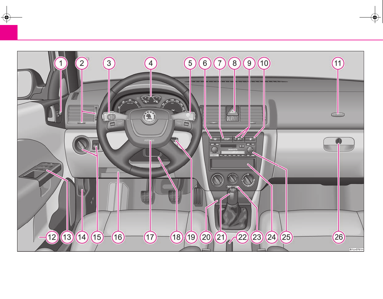
Fig. 1 Certain items of equipment shown in the illustration are only fitted to particular model versions or are optional items of equipment.
s2g8.b.book Page 8 Tuesday, April 7, 2009 8:53 AM

Cockpit 9
riving Tips General Maintenance Breakdown assistance Technical Data
Cockpit
Overview
This overview will help you to quickly familiarise yourself with the
displays and the control elements.
Electric exterior mirror adjustment* . . . . . . . . . . . . . . . . . . . . . . . . .
Air outlet vents . . . . . . . . . . . . . . . . . . . . . . . . . . . . . . . . . . . . . . . . . . . . .
Lever for the multi-functional switch:
−Turn signal light, headlight and parking light, headlight flasher
−Cruise control system* . . . . . . . . . . . . . . . . . . . . . . . . . . . . . . . . . . .
Instrument cluster: Instruments and indicator lights . . . . . . . . . . .
Lever for the multi-functional switch:
−Multi-functional indicator* . . . . . . . . . . . . . . . . . . . . . . . . . . . . . . .
−Windshield wiper and wash system . . . . . . . . . . . . . . . . . . . . . . .
Switch for rear window heater
Depending on equipment fitted:
−Switch for the ESP* . . . . . . . . . . . . . . . . . . . . . . . . . . . . . . . . . . . . . .
−Switch for the TCS* . . . . . . . . . . . . . . . . . . . . . . . . . . . . . . . . . . . . . .
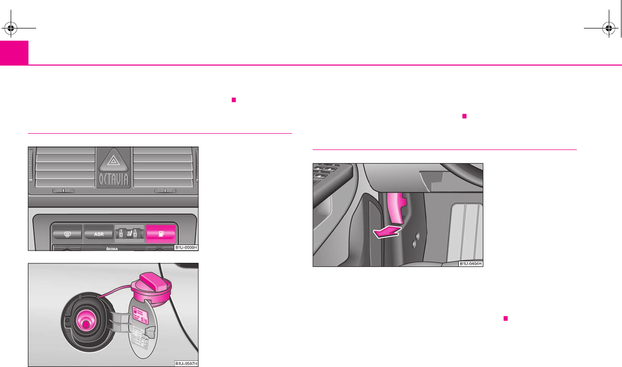
Switch for hazard warning lights . . . . . . . . . . . . . . . . . . . . . . . . . . . . .
Control dial for heating on the driver and front passenger seat*
Open fuel filler cap from the inside* . . . . . . . . . . . . . . . . . . . . . . . . .
Front passenger airbag* . . . . . . . . . . . . . . . . . . . . . . . . . . . . . . . . . . . .
Storage compartment in the front door
Central locking switch and power windows* . . . . . . . . . . . . . . . . . .
Bonnet release lever . . . . . . . . . . . . . . . . . . . . . . . . . . . . . . . . . . . . . . . .
Light switch, headlamp beam adjustment . . . . . . . . . . . . . . . . . . . .
Storage compartment below steering wheel
Steering wheel:
−with horn
−with driver airbag . . . . . . . . . . . . . . . . . . . . . . . . . . . . . . . . . . . . . . . .
Lever for adjusting the steering wheel . . . . . . . . . . . . . . . . . . . . . . . .
Ignition lock . . . . . . . . . . . . . . . . . . . . . . . . . . . . . . . . . . . . . . . . . . . . . . .
Ashtrays . . . . . . . . . . . . . . . . . . . . . . . . . . . . . . . . . . . . . . . . . . . . . . . . . . .
Gearshift lever (manual gearbox) . . . . . . . . . . . . . . . . . . . . . . . . . . . .
Handbrake . . . . . . . . . . . . . . . . . . . . . . . . . . . . . . . . . . . . . . . . . . . . . . . .
Depending on equipment fitted:
−Operating controls for the heating . . . . . . . . . . . . . . . . . . . . . . . .
−Operating controls for the air conditioning system* . . . . . . . .
−Operating controls for Climatronic* . . . . . . . . . . . . . . . . . . . . . . .
Storage compartment in the middle part of the dash panel
Radio*
Storage compartment on the front passenger side . . . . . . . . . . . .
Note
•Equipment which is marked * is only standard on certain vehicle model
versions or only suppliable as optional equipment for certain models.
•Vehicles with factory-fitted radio, mobile phone etc, are supplied with separate
instructions for operating such equipment.
•The arrangement of the controls and switches and the location of some items
on right-hand drive models may differ from that shown in ⇒page 8, fig. 1. The
symbols on the controls and switches are the same as for left-hand drive models.
A
158
A
283
A
3
52
98
A
416
A
5
19
56
A
6
A
7
131
133
A
852
A
967
A
10 156
A
11 116
A
12
A
13 40, 44
A
14 159
A
15 49, 51
A
16
A
17
116
A
18 93
A
19 94
A
20 77
A
21 96
A
22 97
A
23
83
85
89
A
24
A
25
A
26 80
s2g8.b.book Page 9 Tuesday, April 7, 2009 8:53 AM
The brief instruction10
The brief instruction
Basic functions and important information
Introduction
The chapter of the brief instruction is only used as a quick reference
of the most important operating elements of the vehicle. It is neces-
sary to observe all the information which is contained in the
following chapters of the Owner's Manual.
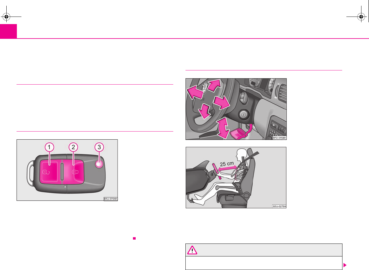
Unlocking and locking the vehicle
Unlocking the vehicle
Locking the vehicle
Folding out/folding up of the key
Further information ⇒page 42, “Unlocking and locking car”.
Setting steering wheel position
You can set the height and the forward/back position of the steering wheel to the
desired position.
Further information ⇒page 93, “Setting steering wheel position”.
WARNING
•Adjust the steering wheel so that the distance between the steering
wheel and your chest is at least 25 cm ⇒fig. 4. Not maintaining this
Fig. 2 Remote control key
A
1
A
2
A
3
Fig. 3 Adjustable steering
wheel: Lever on the steering
column
Fig. 4 The correct distance of
the driver from the steering
wheel
s2g8.b.book Page 10 Tuesday, April 7, 2009 8:53 AM
The brief instruction 11
riving Tips General Maintenance Breakdown assistance Technical Data
minimum distance will mean that the airbag system will not be able to prop-
erly protect you - hazard!
•You must not adjust the steering wheel when the vehicle is moving!
•For safety reasons the lever must always be firmly pushed up to avoid the
steering wheel altering its position unintentionally when driving - risk of
accident!
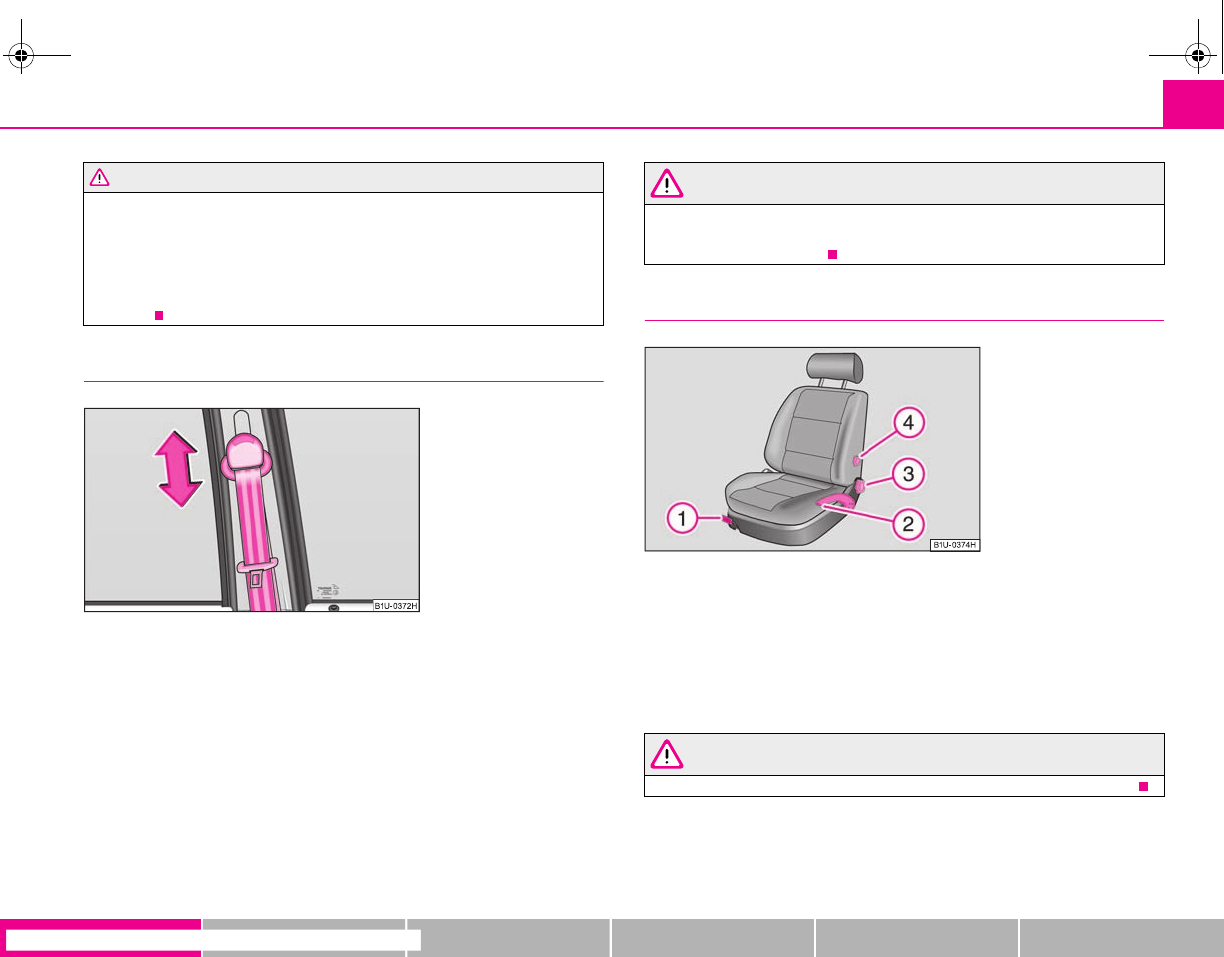
Seat belt height adjuster
– In order to adjust the height, press on the upper seat belt deflection
and push it into the desired direction up or down so that the shoulder
part of the belt is positioned approximately across the middle of your
shoulder.
– Then pull firmly on the belt to ensure that the seat belt height adjuster
has correctly locked in place.
Further information ⇒page 111, “Seat belt height adjuster”.
WARNING
Adjust the height of the belt in such a way that the shoulder part of the belt
is positioned approximately across the middle of your shoulder - on no
account across your neck!
Adjusting the front seats
Adjusting a seat in a forward/back direction
Adjusting height of seat*
Adjust the angle of the seat backrest
Adjusting lumbar support*
Further information ⇒page 60, “Adjusting the front seats”.
WARNING
Only adjust the driver seat when the vehicle is stationary - risk of injury!
WARNING (continued)
Fig. 5 Front seat: Seat belt
height adjuster
Fig. 6 Controls at seat
A
1
A
2
A
3
A
4
s2g8.b.book Page 11 Tuesday, April 7, 2009 8:53 AM
The brief instruction12
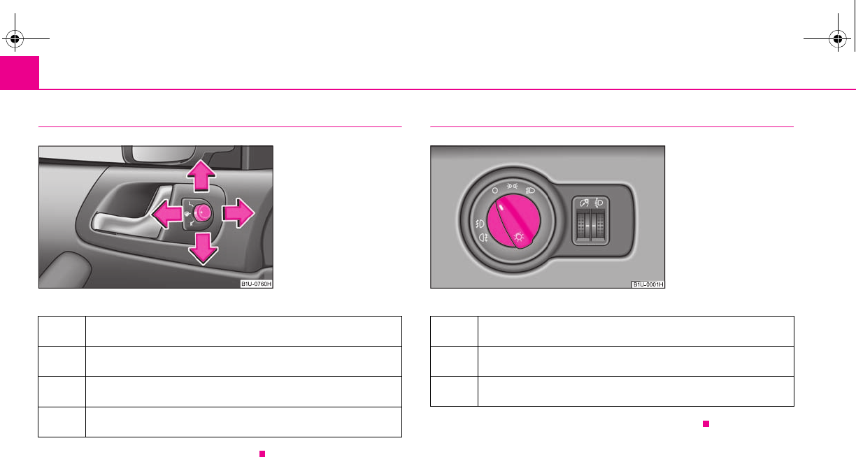
Electric exterior mirror adjustment*
Further information ⇒page 58, “Exterior mirror”.
Switching lights on and off
Further information ⇒page 49, “Switching lights on and off”.
Heating of the external mirror
Adjusting left and right exterior mirrors simultaneously
Adjusting the right-hand exterior mirror
Switching off operating control
Fig. 7 Inner part of door:
Rotary knob
Switching off all lights
Switching on side lights
Switching on the low beam and main beam
Fig. 8 Dash panel: Light
switch
s2g8.b.book Page 12 Tuesday, April 7, 2009 8:53 AM
The brief instruction 13
riving Tips General Maintenance Breakdown assistance Technical Data
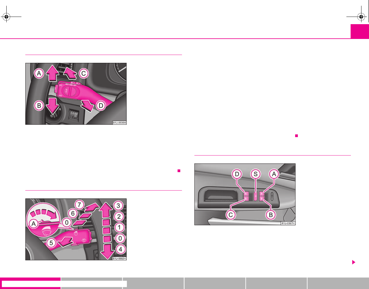
Turn signal and main beam lever
Turn signal light right
Turn signal light left
Switching over between low beam and main beam lights
Headlight flasher
Further information ⇒page 52, “The turn signal and main beam lever ”.
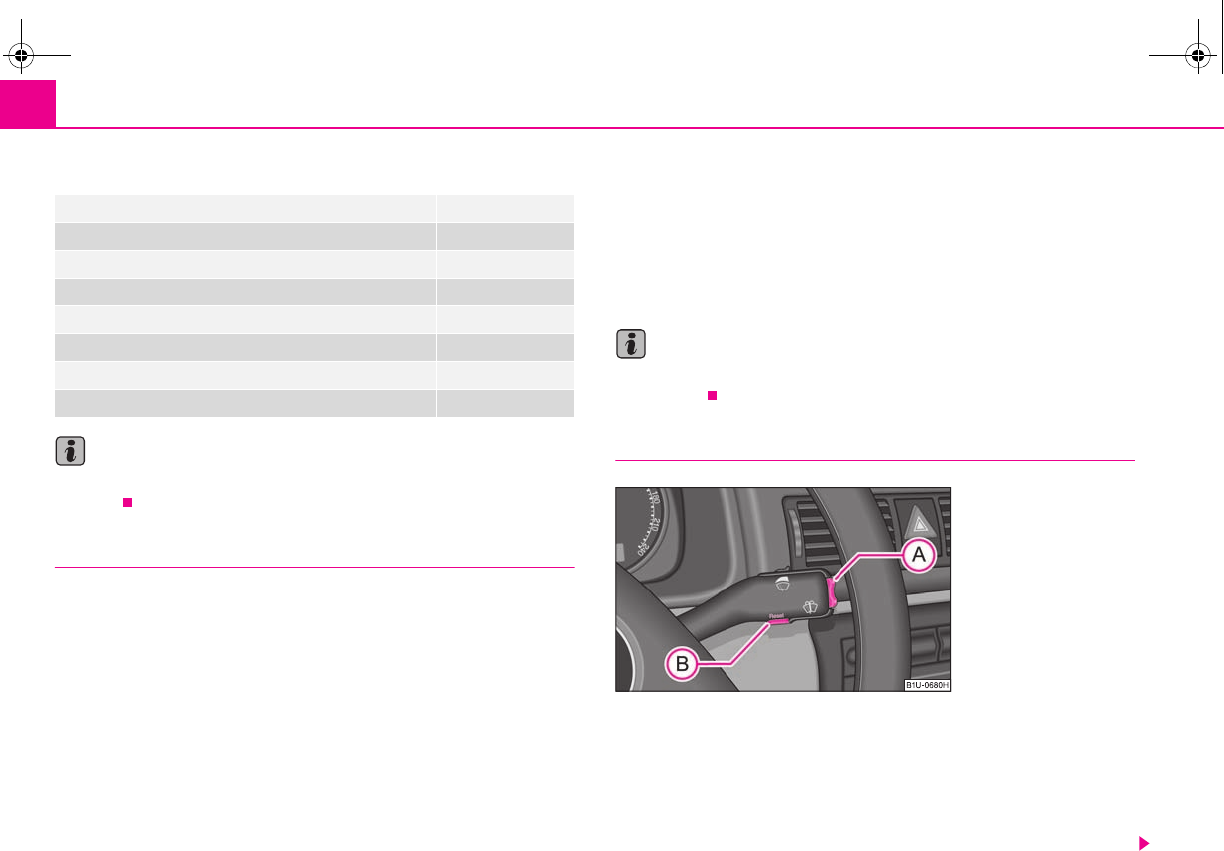
Windscreen wiper lever
Intermittent switch, sensitivity setting rain sensor*
Wipers off
Intermittent wipe
Slow wipe
Fast wipe
one time wipe
Automatic wipe/wash
Rear window wiper*
Intermittent wipe - every 6 seconds
Automatic wipe/wash
Further information ⇒page 56, “Windshield wiper”.
Power windows*
Button for the power window in the driver's door
Button for the power window in the front passenger's door
Button for the power window at the rear right door
Button for the power window at the rear left door
Fig. 9 Turn signal and main
beam lever
A
A
A
B
A
C
A
D
Fig. 10 Windscreen wiper
lever
A
A
A
0
A
1
A
2
A
3
A
4
A
5
A
6
A
7
Fig. 11 Buttons on the
driver's door
A
A
A
B
A
C
A
D
s2g8.b.book Page 13 Tuesday, April 7, 2009 8:53 AM
The brief instruction14
Safety switch
Further information ⇒page 44, “Buttons on the driver's door”.
Refuelling
– Open the fuel filler flap with the hand or open it from the driver seat*
⇒fig. 12.
– The fuel filler cap on the fuel filler tube must be unlocked to the left
using the vehicle key (only valid for vehicles which do not have auto-
matic unlocking of the fuel filler flap).
– Unscrew the fuel filler cap anti-clockwise and place the fuel filler cap
from above on the fuel filler flap ⇒fig. 13.
Further information ⇒page 156, “Refuelling”.
Bonnet remote release
– Pull the unlocking lever below the dash panel on the driver's side
⇒fig. 14.
Further information ⇒page 159, “Bonnet remote release”.
A
S
Fig. 12 Switch for opening
the fuel filler flap from the
driver seat
Fig. 13 Fuel filler flap with
cap unscrewed
Fig. 14 Bonnet release lever
s2g8.b.book Page 14 Tuesday, April 7, 2009 8:53 AM
The brief instruction 15
riving Tips General Maintenance Breakdown assistance Technical Data
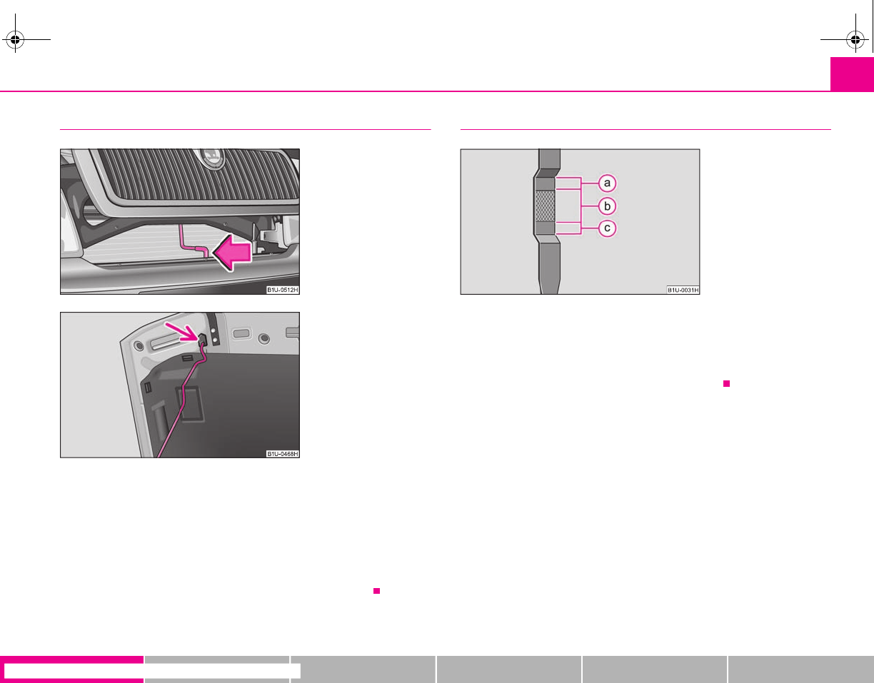
Opening the bonnet
– Grip with the hand under the radiator grille and lift up the bonnet.
– Press the locking lever in direction of arrow ⇒fig. 15 and lift up the
bonnet.
– Take the bonnet support out of its holder and set it in the opening
designed for it ⇒fig. 16.
Further information ⇒page 159, “Opening and closing the bonnet.”.
Inspecting the engine oil level
Engine oil must not be refilled.
Engine oil can be refilled.
Engine oil must be refilled.
Further information ⇒page 163, “Check engine oil level”.
Fig. 15 Radiator grille:
Locking lever
Fig. 16 Securing the bonnet
with the bonnet support
Fig. 17 Dipstick
A
a
A
b
A
c
s2g8.b.book Page 15 Tuesday, April 7, 2009 8:53 AM
Instruments and Indicator/Warning Lights16
Instruments and Indicator/Warning Lights
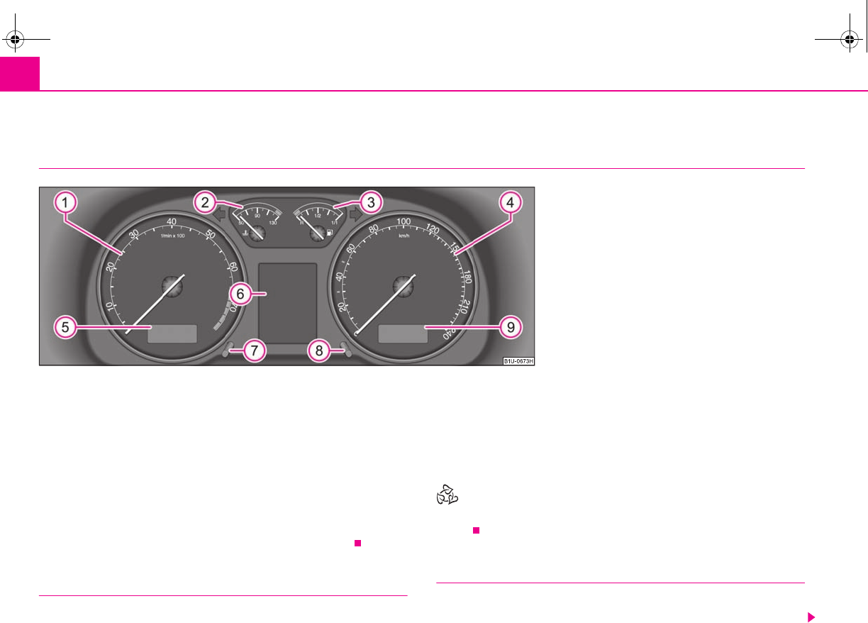
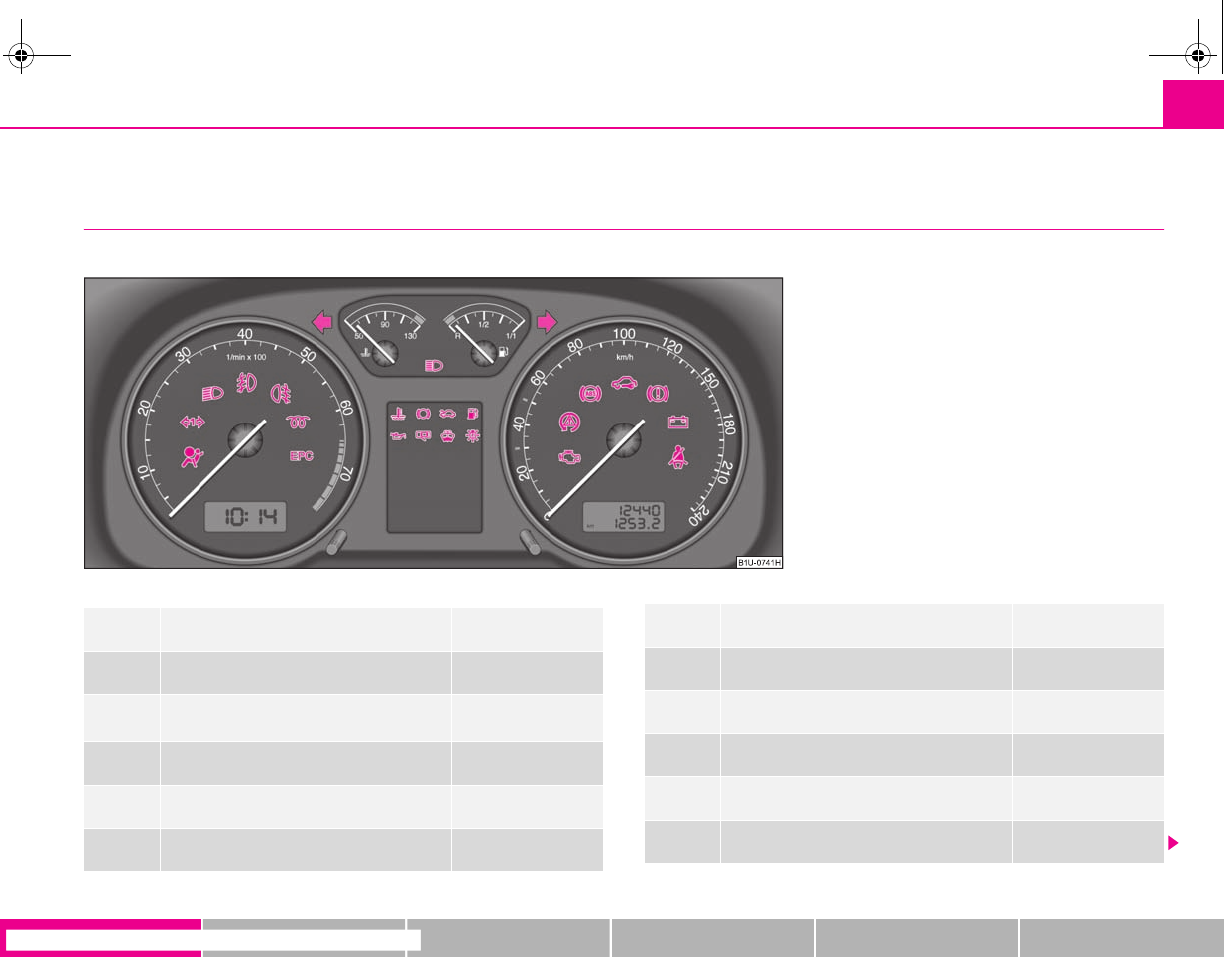
General view of the instrument cluster
Engine revolutions counter ⇒page 16
Coolant temperature gauge ⇒page 16
Fuel gauge ⇒page 17
Speedometer ⇒page 17
Digital clock, Multi-functional indicator* ⇒page 19
Information display* ⇒page 23
Clock-set button ⇒page 19
Reset button ⇒page 18
Odometer and trip counter, service interval display ⇒page 18
When the lights are switched on, the instrument cluster is illuminated.
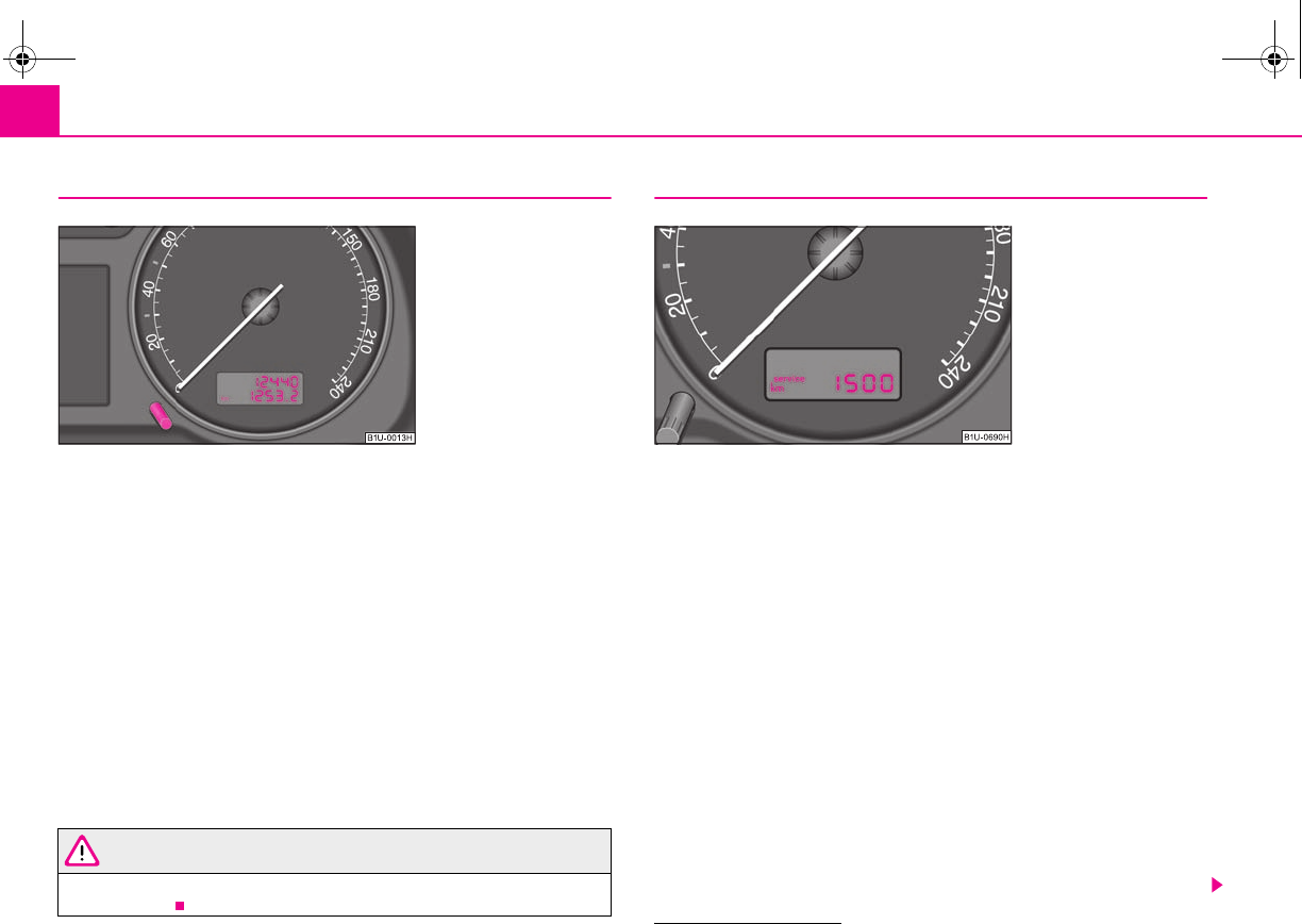
Engine revolutions counter
The start of the red zone in the revolutions counter ⇒fig. 18 indicates the
maximum permissible engine speed for all gears for an engine which has been run
in and operating at a normal temperature. Before reaching this zone shift up into
the next higher gear.
One should shift to a lower gear at the latest when the engine is no longer running
“smoothly”.
Avoid high engine speeds when running-in the vehicle ⇒page 137.
For the sake of the environment
Shifting up early helps you save fuel and reduce the operating noise of your
vehicle.
Coolant temperature gauge
The coolant temperature gauge ⇒fig. 18 operates only when the ignition is
switched on.
Fig. 18 Instrument cluster
A
1
A
2
A
3
A
4
A
5
A
6
A
7
A
8
A
9
A
1
A
2
s2g8.b.book Page 16 Tuesday, April 7, 2009 8:53 AM
Instruments and Indicator/Warning Lights 17
riving Tips General Maintenance Breakdown assistance Technical Data
In order to avoid any damage to the engine, please pay attention to the following
notes regarding the temperature ranges:
Cold range
If the pointer is in the left-hand area of the scale it means that the engine has not
yet reached its operating temperature. Avoid running at high engine speeds, at full
throttle and at severe engine loads.
The operating range
The engine has reached its operating temperature as soon as the pointer moves
into the mid-range of the scale. The pointer may also move further to the right at
high engine loads and high outside temperatures. This is not critical provided the
warning symbol in the instrument cluster does not flash.
If the symbol in the instrument cluster flashes it means that either the coolant
temperature is too high or the coolant level is too low. Observe the guidelines
⇒page 30, “Coolant temperature/ Coolant quantity ”.
WARNING
Pay attention to the warning notes ⇒page 160, “Working in the engine
compartment” before opening the bonnet and inspecting the coolant level.
Caution
Additional headlights and other attached components in front of the fresh air inlet
impair the cooling efficiency of the coolant. There is then a risk of the engine over-
heating at high outside temperatures and high engine loads!
Fuel gauge
The fuel gauge ⇒page 16, fig. 18 only operates when the ignition is switched
on.
The fuel tank has a capacity of about 55 litres. The warning symbol in the instru-
ment cluster lights up when the pointer reaches the reserve marking. There are now
about 7 litres of fuel remaining in the tank. This symbol is a reminder for you, that
you must refuel.
The following will be displayed in the information display*:
PLEASE REFUEL
A peep sounds as an additional warning signal.
Caution
Never run the fuel tank completely empty! An irregular fuel supply can result in
poor ignition or misfiring. Unburnt fuel may get into the exhaust system and
damage the catalytic converter.
Speedometer
Warning against excessive speeds*
An acoustic warning signal will sound when the vehicle speed exceeds 120 kilome-
tres per hour. The acoustic warning signal will switch off again when the vehicle
speed goes below this speed limit.
Note
This function is only valid for some countries.
A
3
s2g8.b.book Page 17 Tuesday, April 7, 2009 8:53 AM
Instruments and Indicator/Warning Lights18
Counter for distance driven
The distance which you have driven with your vehicle is shown in kilometres (km).
On certain model versions, the readout is shown in “miles”.
Bottom (trip) counter for distance driven
The trip counter indicates the distance which you have driven since it was last reset
- in steps of 100 metres or 1/10 of a mile. The bottom counter can be reset by
pressing the reset button of the trip counter ⇒fig. 19.
Top counter for distance driven
The top counter indicates the total distance driven in kilometres or miles which the
vehicle has been driven.
Fault display
dEF appears permanently in the trip counter display for distance driven if there is a
fault in the instrument cluster. Have the fault rectified as soon as possible by a
specialist workshop.
WARNING
Never seek to adjust the trip counter for distance driven while driving for
safety reasons!
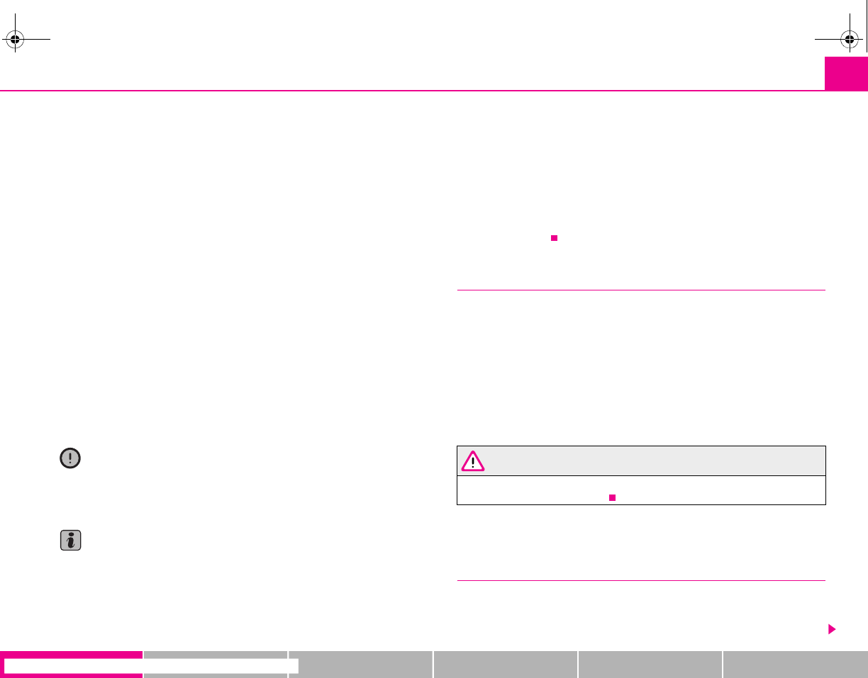
Service Interval Display
Depending on the equipment installed in the vehicle, the text can differ slightly on
the display.
Service Interval Display
If the due date for the service is reached, it is displayed1):
in the display of the trip counter:
Service 1 500 km
in the information display:
SERVICE in 1500 km
The kilometre readout decreases in steps of 100°km.
If the due date for the service is reached, the following text appears as a flashing
display:
in the display of the trip counter:
Service
in the information display:
SERVICE NOW
Fig. 19 Instrument cluster:
Counter for distance driven
1) On some vehicles, the service interval display service OIL or service INSP is shown.
Fig. 20 Service Interval
Display: Note
s2g8.b.book Page 18 Tuesday, April 7, 2009 8:53 AM
Instruments and Indicator/Warning Lights 19
riving Tips General Maintenance Breakdown assistance Technical Data
The display disappears within 20 seconds after switching on the ignition. The trip
counter is also displayed after pressing the reset button for the trip counter (for
more than 0.5 second).
Resetting Service Interval Display
It is only possible to reset the Service Interval Display, if a service message or at least
a pre-warning is shown on the display of the instrument cluster.
We recommend having this resetting performed by a specialist garage.
The specialist garage:
•resets the memory of the display after the appropriate inspection;
•makes an entry in the Service schedule;
•affix the sticker with the entry of the following service interval to the side of the
dash panel on the driver's side.
The service interval display can also be reset with the reset button as follows
⇒page 16, fig. 18:
•Press the reset button with the ignition switched off and and hold it down.
•Switch the ignition on, release the reset button. The text Service or SERVICE
NOW appears in the display.
•Turn the button for setting the clock to the right - as a result of this the display is
reset.
Caution
We recommend that you do not reset the Service Interval Display yourself other-
wise this can result in the service interval display being incorrectly set, which may
also result in problems with operation of your vehicle.
Note
•Never reset the display between service intervals otherwise this may result in
incorrect readouts.
•information is retained in the Service Interval Display also after the battery of
the vehicle is disconnected.
•it is necessary to re-code the Service Interval Display if a new instrument cluster
is installed during repair work. This work is carried out by a specialist garage.
•The data displayed is the same after resetting the display with flexible service
intervals (QG1) using the reset button as that for a vehicle with fixed service inter-
vals (QG2). We therefore recommend having the Service Interval Display reset only
by a specialist garage which is familiar with the procedure for resetting the display
with a vehicle system tester.
•Please refer to the brochure Service schedule for extensive information about
the service intervals.
Digital clock
A clock-set button is installed on the bottom left beside the speedom-
eter for adjusting the clock ⇒page 16, fig. 18.
Set hours
– Turn the reset button to the left.
Setting minutes
– Turn the reset button to the right.
WARNING
The clock should not be adjusted while driving for safety reasons but only
when the vehicle is stationary!
Multi-functional indicator (onboard computer)*
Introduction
The multi-functional indicator appears in the display of the revolutions counter or
in the information display depending on the equipment fitted to your vehicle
⇒page 23, fig. 23.
A
8
A
7
s2g8.b.book Page 19 Tuesday, April 7, 2009 8:53 AM
Instruments and Indicator/Warning Lights20
The multi-functional indicator offers you a range of useful information.
Note
In certain national versions the displays appear in the Imperial system of
measures.
Memory
The multi-functional indicator is equipped with two automatic memories.
The data of the single-trip memory (memory 1) is shown if a 1 appears in the
display. A 2 shown in the display means that data relates to the total distance
memory (memory 2).
Switching of the memory takes place when the button ⇒fig. 21.
Single-trip memory (memory 1)
The single-trip memory collates the driving information from the moment the igni-
tion is switched on until it is switched off. New data will also flow into the calcula-
tion of the current driving information if the trip is continued within 2 hours after
switching off the ignition. The memory will be is automatically erased, on the other
hand, if the trip is interrupted for more than 2 hours.
Total-trip memory (memory 2)
The total distance driven memory gathers data from any number of individual jour-
neys up to a total of 99 hours and 59 minutes driving or 9.999 kilometres driven.
The memory is deleted when either of these limits is reached and the calculation
starts from anew.
The total-trip memory will not, contrary to the single-trip memory, be deleted after
a period of interruption of driving of 2 hours.
Note
All information in the memory is erased if the battery of the vehicle is
disconnected.
Using the system
The rocker switch and the button are located in the grip of the
window wiper lever ⇒fig. 21.
Selecting the memory
– Repeated short-term pressing of the button allows to select the
desired memory.
The outside temperature ⇒page 21
Current fuel consumption ⇒page 21
Average fuel consumption ⇒page 22
Range ⇒page 22
Distance driven ⇒page 22
Average speed ⇒page 22
Driving time ⇒page 22
Time
A
B
Fig. 21 Multi-functional
indicator: Control elements
A
A
A
B
A
B
s2g8.b.book Page 20 Tuesday, April 7, 2009 8:53 AM
Instruments and Indicator/Warning Lights 21
riving Tips General Maintenance Breakdown assistance Technical Data
Selecting the functions
– Press the rocker switch up or down. This will cause the individual
functions of the multi-functional indicator to appear in the display
one after the other.
Setting function to zero
– Select the memory you want.
– Press button for more than 1 second.
The following readouts of the selected memory will be set to zero by button :
•average fuel consumption,
•distance driven,
•average speed,
•Driving time.
You can only operate the multi-functional indicator when the ignition is switched
on. After the ignition is switched on, the function displayed is the one which you last
selected before switching off the ignition.
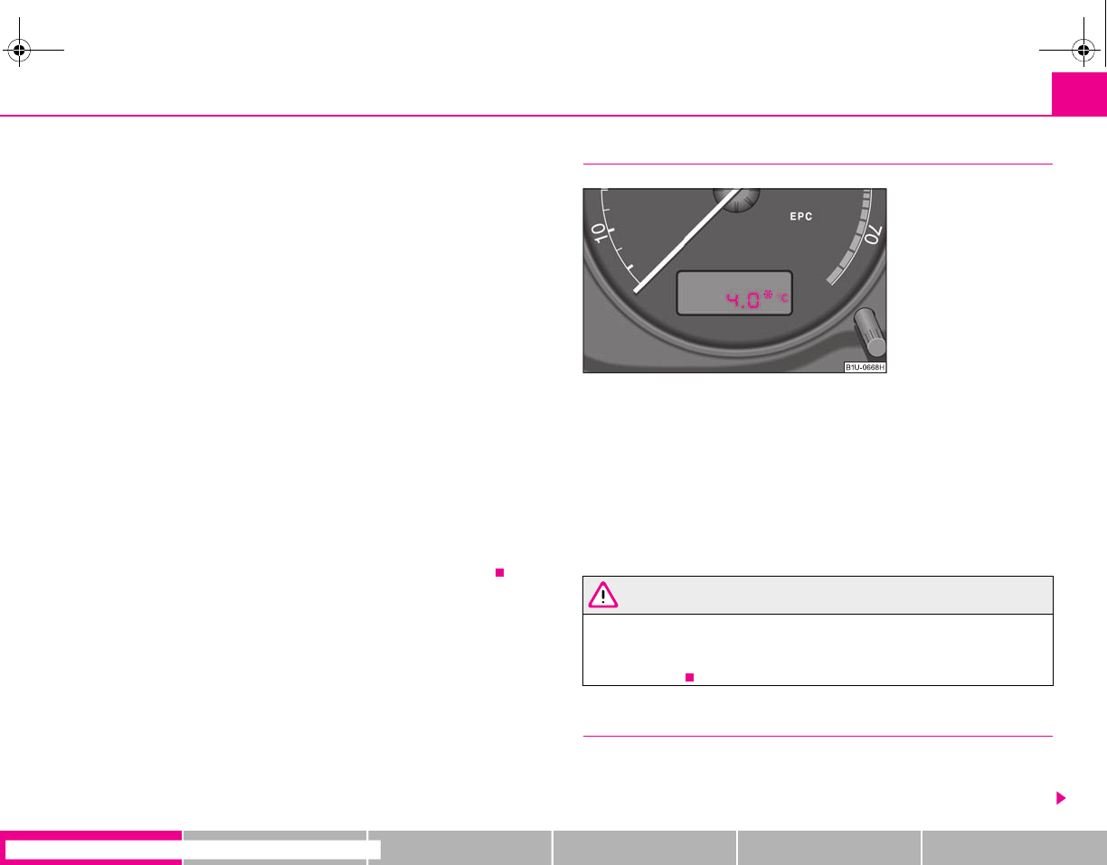
If the outside temperature drops below +4 °C, the outside temperature indicator
with a snow flake symbol appears. The symbol warns the driver of the possible
danger of ice on the road. After the rocker switch is pressed, the function
displays the one which you last selected before switching off the ignition.
Outside temperature
The outside temperature appears in the display when the ignition is switched on.
The correct outside temperature will be indicated with a delay of 5 minutes. If the
vehicle is stationary (or driven at a very low speed) the temperature indicated may
be slightly higher than the actual outside temperature because of heat radiated by
the engine.
If the outside temperature drops below +4°C, a snow flake symbol (warning signal
for ice on the road) appears behind the temperature indicator ⇒fig. 22 and a
warning signal sounds.
WARNING
Do not only rely upon the information given on the outside temperature
display that there is no ice on the road. Please note that black ice may also be
present on the road surface even at temperatures around +4°C - warning,
drive with care!
Current consumption
The current fuel consumption level is shown in the display in litres/100 km. This
information can help you to adapt your style of driving to the fuel consumption you
wish to achieve.
A
A
A
B
A
B
A
A
Fig. 22 Multi-functional
indicator: the outside
temperature
s2g8.b.book Page 21 Tuesday, April 7, 2009 8:53 AM

Instruments and Indicator/Warning Lights22
The display appears in litres/hour if the vehicle is stationary or driving at a low
speed.
Average fuel consumption
The average fuel consumption since the memory was last erased is shown in the
display in litres/100 km ⇒page 20. This information can help you to adapt your
style of driving to the fuel consumption you wish to achieve.
If you wish to determine the average fuel consumption over a certain period of time
you must first erase the memory at the start of the new measurement using the
button ⇒page 20, fig. 21. A zero appears in the display for the first 300 m you
drive after erasing the memory.
The indicated value will be updated every 5 seconds while you are driving.
Note
The amount of fuel consumed will not be indicated.
Range
The estimated range in kilometres is shown on the display. It indicates the distance
you can still drive with your vehicle based on the present level of fuel in the tank for
the same style of driving. The readout is shown in steps of 10 km.
The fuel consumption for the last 50 km is taken as a basis for calculating the range.
If you drive in a more economical manner from this moment on, the range will be
increased accordingly.
You first drive 50 km if the readout is reset (after disconnecting the battery) before
a new readout for the range is displayed.
Distance driven
The distance driven since the memory was last erased appears in the display
⇒page 20. If you wish to calculate the distance driven from a particular time of day
you must first erase the memory at this moment in time by pressing the button
⇒page 20, fig. 21.
The maximum distance indicated in both switch positions is 9 999 km. The indicator
is set back to null if this period is exceeded.
Average speed
The average speed since the memory was last erased is shown in the display in
km/hour ⇒page 20. If you wish to determine the average speed over a certain
period of time you must first erase the memory at the start of the new measure-
ment using the button ⇒page 20, fig. 21.
A zero appears in the display for the first 300 m you drive after erasing the memory.
The indicated value will be updated every 5 seconds while you are driving.
Driving time
The driving time which has elapsed since the memory was last erased, appears in
the display ⇒page 20. If you wish to calculate the driving time from a particular
time of day you must first erase the memory at this moment in time by pressing the
button ⇒page 20, fig. 21.
The maximum distance indicated in both memories is 99 hours and 59 minutes.
The indicator is set back to null if this period is exceeded.
Warning against excessive speeds*
An acoustic warning signal will sound when the vehicle speed exceeds 120 kilome-
tres per hour. The acoustic warning signal will switch off again when the vehicle
speed goes below this speed limit.
This function is only valid for some export countries.
A
B
A
B
A
B
A
B
s2g8.b.book Page 22 Tuesday, April 7, 2009 8:53 AM
Instruments and Indicator/Warning Lights 23
riving Tips General Maintenance Breakdown assistance Technical Data
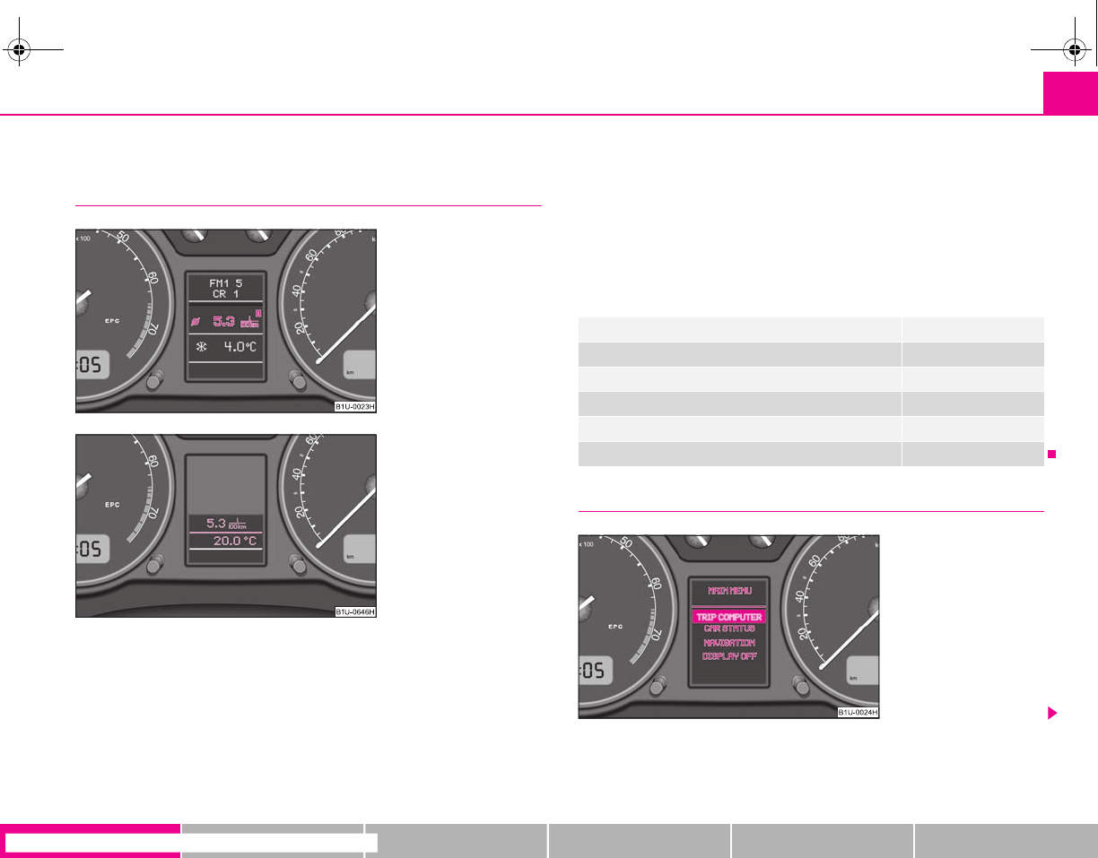
Information display*
Introduction
The information display provides you with information in a convenient way
concerning the current operating state of your vehicle. The information system
also provides you with data (depending on the equipment installed in the vehicle)
relating to the radio and multi-functional indicator.
Certain functions and operating conditions are always being checked on the
vehicle when the ignition is switched on and also while driving.
Functional faults, if required repair work and other information are indicated by red
symbols and yellow symbols.
Lighting up of these symbols is combined with an acoustic warning signal.
Information and texts giving warnings are also shown in the display ⇒page 27.
The display of text is possible in the following languages:
Czech, English, German, French, Italian, Spanish, Portuguese.
The desired language can be set by a specialist garage.
The following information can be shown in the display (depending on the equip-
ment installed on the vehicle):
Menu
Fig. 23 Instrument cluster:
large information display
Fig. 24 Instrument cluster:
small information display
Menu ⇒page 23
Door and boot lid warning ⇒page 24
Displays of the multi-functional indicator ⇒page 16
Warning symbols or warning lights ⇒page 27
Displays of the Service Interval Display ⇒page 18
Displays of the radio
Fig. 25 Information display:
Menu
s2g8.b.book Page 23 Tuesday, April 7, 2009 8:53 AM
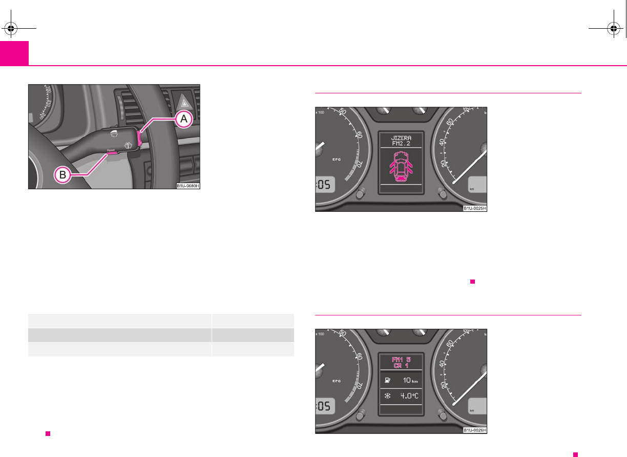
Instruments and Indicator/Warning Lights24
– You can activate the menu by pressing the rocker switch ⇒fig. 26
for more than 1 second.
– You can select individual menu points by means of the rocker switch
. The selected information is displayed after pressing the button
for a short time or after releasing the rocker switch (after about 4
seconds).
You can select the following information (depending on the equipment installed on
the vehicle):
After selecting the menu point DISPLAY OFF the display is switched off. Press the
rocker switch for more than 1 second to switch the display on again.
The Information CAR STATUSflashes in the menu if there is something which is not
in proper order on the vehicle (e.g. warning of a low fuel level). The first warning will
be displayed after switching over to CAR STATUS. You can then display other oper-
ating conditions afterwards using the switch-over function (such as water level
low).
Door and boot lid warning
The door and boot lid warning lights up if at least one door or the boot lid is not
closed. The symbol displays the respective opened door and boot lid ⇒fig. 27.
The symbol goes out as soon as the doors and the boot lid are completely closed.
As an additional warning signal, a 3 time peep sounds if the car is driven at a speed
of more than 6km/hour and if the door is open.
Radio display
These displays indicate the common information from the display of the radio.
TRIP COMPUTER (AUTO COMPUTER) ⇒page 19
CAR STATUS ⇒page 25
DISPLAY OFF
Fig. 26 Information display:
Control elements
A
A
A
A
A
B
A
A
A
A
Fig. 27 Information display:
Door warning
Fig. 28 Information display:
Radio display
s2g8.b.book Page 24 Tuesday, April 7, 2009 8:53 AM
Instruments and Indicator/Warning Lights 25
riving Tips General Maintenance Breakdown assistance Technical Data
Auto Check Control
Car state
The Auto Check Control carries out a check of certain functions and vehicle compo-
nents. The check is performed constantly when the ignition is switched on, both
when the vehicle is stationary, as well as when driving.
Operational faults, urgent repairs, service work or other information appear in the
display of the instrument cluster. The displays are shown with a red or yellow light
symbol depending on the priority of the message.
The red symbols indicate danger (priority 1) while the yellow symbols indicate a
warning (priortity 2). Information for the driver may also appear in addition to the
symbols ⇒page 27.
Investigate the displayed faults as soon as possible. If several operational faults exist
at the same time, the symbols will appear one after the other and are each visible
for about 2 seconds.
The error messages are faded out after 10 seconds or by actuating the rocker switch
⇒page 24, fig. 26 and are stored under the information CAR STATUS.
There is at least one error message to be read when the term CAR STATUS is
flashing in the menu. The display will show STATUS 1/2 (for example) if a number
of error messages are present. This display indicates that the first of a total of two
error messages should be displayed.
Actuate the rocker switch , to call up the individual error messages.
If a fault occurs, a warning signal will also sound in addition to the symbol and text
in the display:
•Priority 1 - three warning signals
•Priority 2 - one warning signal
Red symbols
A red symbol signals danger.
Proceed as follows if a red symbol is displayed:
– Stop the vehicle.
– Switch the engine off.
– Check the functions indicated.
– Obtain professional assistance.
Meaning of the red symbols:
Three successive warning signals will sound if a red symbol appears. The symbol
continues flashing until the fault is rectified.
A
A
A
A
Faults in the brake surface ⇒page 34
Coolant level too low/coolant temperature
too high ⇒page 30
Engine oil pressure too low ⇒page 31
Fig. 29 Information display:
Oil pressure is low
s2g8.b.book Page 25 Tuesday, April 7, 2009 8:53 AM
Instruments and Indicator/Warning Lights26
If several operational faults of priority 1 exist, the symbols appear one after the
other and are each illuminated for about 2 seconds.
Yellow symbols
A yellow symbol signals a warning.
The meaning of the yellow symbols:
One warning signal will sound if a yellow symbol appears.
If several operational faults of priority 2 exist, the symbols appear one after the
other and are each illuminated for about 2 seconds.
Check the relevant function as soon as possible.
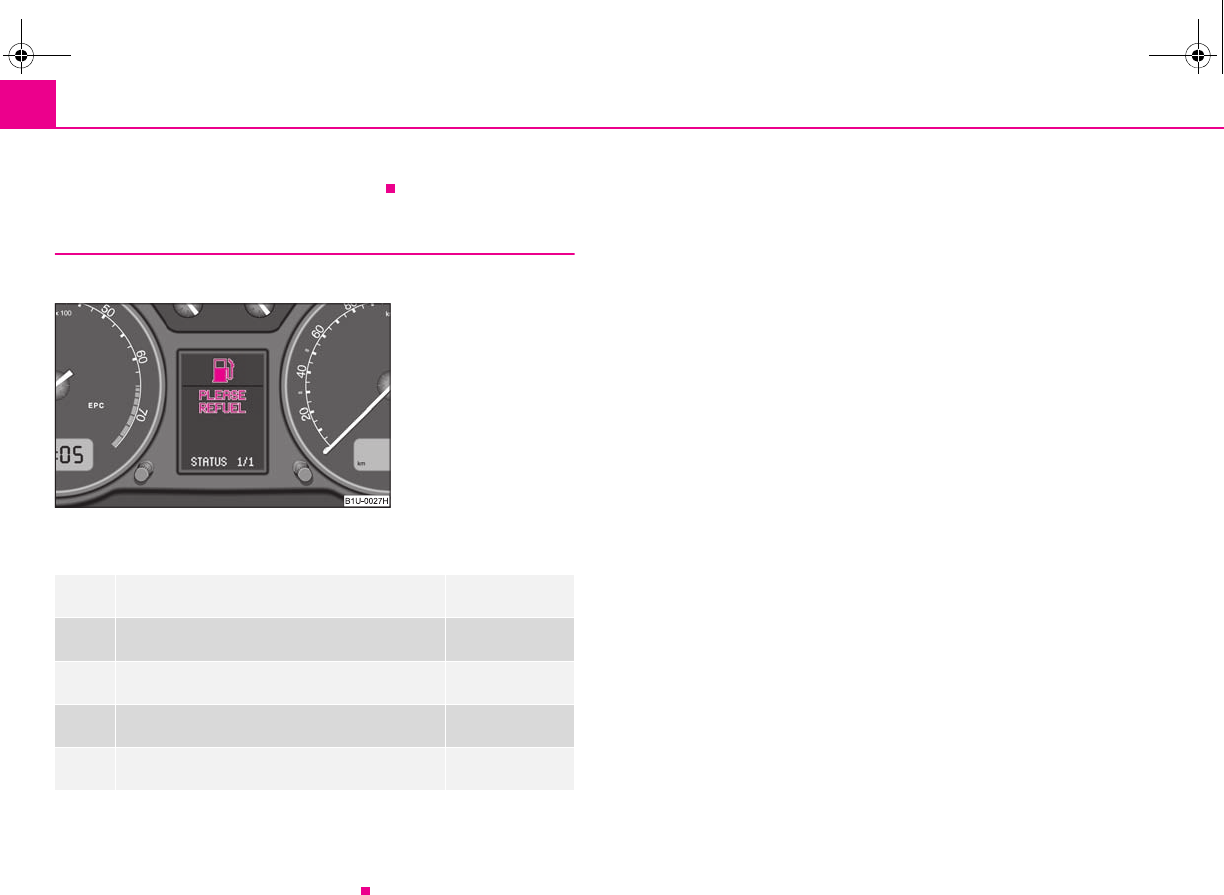
Fuel level low ⇒page 31
Check engine oil level, engine oil sensor faulty ⇒page 31
Brake pad worn ⇒page 31
Washer fluid level low ⇒page 31
faulty bulb ⇒page 29
Fig. 30 Information display:
Fuel level low
s2g8.b.book Page 26 Tuesday, April 7, 2009 8:53 AM
Instruments and Indicator/Warning Lights 27
riving Tips General Maintenance Breakdown assistance Technical Data
Warning lights
Overview
The warning lights indicate certain functions or faults.
Fig. 31 Instrument cluster with warning lights
Turn signal lights (to the left) ⇒page 28
Turn signal lights (to the right) ⇒page 28
Turn signal system for vehicles towing a
trailer* ⇒page 28
Main beam light ⇒page 29
Low beam light ⇒page 29
Fog lights* ⇒page 29
Rear fog light ⇒page 29
Electronic immobiliser ⇒page 29
Bulbs* ⇒page 29
Control system for exhaust ⇒page 29
EPC fault light* (petrol engine) ⇒page 29
Glow plug system (diesel engine) ⇒page 30
s2g8.b.book Page 27 Tuesday, April 7, 2009 8:53 AM
Instruments and Indicator/Warning Lights28
WARNING
•If you do not pay attention to the warning lights coming on and the corre-
sponding descriptions and warning notes, this may result in severe body
injuries or major vehicle damage.
•The engine compartment of your car is a hazardous area. There is a risk
of injuries, scalding, accidents and fire when working in the engine
compartment, e.g. inspecting and replenishing oil and other fluids. It is also
essential to observe all warnings ⇒page 160.
Note
•Arrangement of the indicator lights depends on the model and model version.
The symbols shown in the following functional description are to be found as indi-
cator lights in the instrument cluster.
•Operational faults are shown in the instrument cluster as red symbols (priority
1 - danger) or yellow symbols (priority 2 - warning).
Turn signal system
Either the left or right indicator light flashes depending on the position of the
turn signal lever.
The indicator light flashes at twice its normal rate if a turn signal light fails. This does
not apply when towing a trailer.
Switching off the hazard warning light system is switched on will cause all of the
turn signal lights as well as both indicator lights to flash.
Further information about the turn signal system ⇒page 52.
Turn signal system for vehicles towing a trailer *
The warning light flashes together with the other turn signal lights only if the
vehicle is towing a trailer.
The indicator light does not flash if a turn signal light on the trailer or on the vehicle
is not operating.
Airbag system* ⇒page 30
Coolant temperature/coolant level ⇒page 30
Brake pad wear* ⇒page 31
Fuel reserve ⇒page 31
Engine oil ⇒page 31
Open door* ⇒page 32
Fluid level in windshield washer system* ⇒page 31
Antilock brake system (ABS)* ⇒page 32
Traction control system (TCS)* ⇒page 33
Electronic stability programme (ESP)* ⇒page 33
Dynamo ⇒page 34
Brake system ⇒page 34
Seat belt warning light* ⇒page 34
WARNING (continued)
s2g8.b.book Page 28 Tuesday, April 7, 2009 8:53 AM

Instruments and Indicator/Warning Lights 29
riving Tips General Maintenance Breakdown assistance Technical Data
Main beam
The indicator light comes on when the main beam is selected or also when the
headlight flasher is operated.
Further information about the main beam ⇒page 52.
Low beam
The warning light comes on when low beam is selected ⇒page 49.
Fog lights *
The warning light comes on when the fog lights are operating.
Rear fog light
The warning light comes on when the rear fog lights are operating ⇒page 50.
Electronic immobiliser
Data is compared between the ignition key and the control unit when switching on
the ignition. The indicator light will light up for a few seconds when ignition key
authorisation is confirmed.
The warning light will start flashing continuously if a non-authorised ignition key
(for example the wrong ignition key) has been used. The engine cannot be started
⇒page 36.
It is only possible to start the engine of the vehicle with a Genuine Škoda key with
the matching code.
The following text will be displayed in the information display*:
IMMOBIL. ACTIVATED
Bulbs
The warning light comes on if a bulb is faulty:
•Brakes applied (brake light);
•Switching on the lights (front low beam or rear parking lights).
A peep sounds as an additional warning signal.
Control system for exhaust
The warning light comes on after the ignition has been switched on.
If the warning light does not go out after starting the engine or it lights up or flashes
when driving, a fault exists in an exhaust relevant component. The engine manage-
ment system selects an emergency programme which enables you to drive to the
nearest specialist garage by adopting a gentle style of driving.
The following text will be displayed in the information display*:
EMISSIONS WORKSHOP!
EPC fault light (petrol engine)
The (Electronic Power Control) warning light comes on for a few seconds when
the ignition is switched on.
If the warning light does not go out or lights up after starting the engine, a fault
exists in the engine control. The engine management system selects an emergency
programme which enables you to drive to the nearest specialist garage by adopting
a gentle style of driving.
The following text will be displayed in the information display*:
ENGINE WORKSHOP!
s2g8.b.book Page 29 Tuesday, April 7, 2009 8:53 AM
Instruments and Indicator/Warning Lights30
Glow plug system (diesel engine)
The warning light lights up for a cold engine when switching on the ignition (pre-
heat position) 2 ⇒page 94. Start the engine just as soon as the indicator light goes
out.
The glow plug indicator light will come on for about 1 second if the engine is at a
normal operating temperature or if the outside temperature is above +5°C. This
means that you can start the engine right away.
There is a fault in the glow plug system if the warning light does not come on
at all or lights up continuously. Contact a specialist garage as soon as possible to
obtain assistance.
If the warning light begins to flash while driving, a fault exists in the engine
control. The engine management system selects an emergency programme which
enables you to drive to the nearest specialist garage by adopting a gentle style of
driving.
The following text will be displayed in the information display*:
ENGINE WORKSHOP!
Airbag system
Monitoring the airbag system
The warning light comes on for a few seconds when the ignition is switched on.
There is a fault in the system if the warning light does not go out or comes on or
flashes while driving ⇒. This also applies if the warning light does not come on
when the ignition is switched on.
The following text will be displayed in the information display*:
AIRBAG FAULT
The functionality of the airbag system is also monitored electronically when one
airbag has been switched off.
Front airbag or side passenger airbag deactivated using the diagnostic equip-
ment:
•The warning light lights up for 3 seconds after switching on the ignition and
then flashes again for 12 seconds.
Front passenger airbags switched off using the switch for front passenger
airbags* in storage compartment on the front passenger side:
•The warning light comes on for 3 seconds after the ignition has been
switched on.
•The deactivation of the airbag is indicated by the lighting up of the indicator
light in the interior lighting ⇒page 121.
WARNING
Have the airbag system checked immediately by a specialist garage if a fault
exists. Otherwise, there is a risk of the airbag not being activated in the event
of an accident.
Note
Further information about switching off airbags ⇒page 120.
Coolant temperature/ Coolant quantity
The warning light comes on for a few seconds 2) when the ignition is switched on.
The coolant temperature is too high or the coolant level too low if the warning light
does not go out or flashes while driving.
3 peeps sound as an additional warning signal.
In this case stop and switch the engine off and check the coolant level; top up the
coolant as necessary.
Do not continue your journey if for some reason it is not possible under the
conditions prevailing to top up with coolant. Keep the engine switched off and
2) The warning light on vehicles fitted with information display does not come on after
switching the ignition on, but only if the coolant temperature is too high or the coolant level
is too low.
s2g8.b.book Page 30 Tuesday, April 7, 2009 8:53 AM
Instruments and Indicator/Warning Lights 31
riving Tips General Maintenance Breakdown assistance Technical Data
obtain professional assistance from a specialist garage, otherwise it could lead to
severe engine damage.
If the coolant is within the specified range, the increased temperature may be
caused by an operating problem at the coolant fan. Check the fuse for the coolant
fan, replace it if necessary ⇒page 193, “Fuse assignment in engine compartment -
version 1” or ⇒page 194, “Fuse assignment in engine compartment - version 2”.
Do not continue driving if the warning light does not go off although the fluid is at
the correct level and also the fuse of the fan is in proper order. Contact a specialist
garage to obtain assistance.
Please also refer to the additional instructions ⇒page 165, “Cooling system”.
The following text will be displayed in the information display*:
STOP CHECK COOLANT SERVICE MANUAL
WARNING
•If you must stop for technical reasons, then park the vehicle at a safe
distance from the traffic and switch off the engine and switch on the hazard
warning light system ⇒page 52.
•Take care when opening the coolant expansion bottle. If the engine is hot,
the cooling system is pressurized - risk of scalding! It is best to allow the
engine to cool down before removing the cap.
•Do not touch the coolant fan The coolant fan may switch on automati-
cally even if the ignition is off.
Thickness of the brake pads*
The warning light comes on for a few seconds when the ignition is switched on.
If the warning light comes on, contact a specialist garage immediately and have
the brake pads on all of the wheels inspected.
A peep sounds as an additional warning signal.
The following text will be displayed in the information display*:
CHECK BRAKE PADS
Windshield washer fluid level*
The warning light comes on when the ignition is switched on if there is insuffi-
cient fluid in the windshield washer system. Top up with liquid ⇒page 172.
A peep sounds as an additional warning signal.
The following text will be displayed in the information display*:
TOP UP WASH FLUID
Fuel reserve
The warning light comes on, if the fuel level is still below 7 litres.
A peep sounds as an additional warning signal.
The following text will be displayed in the information display*:
PLEASE REFUEL
Note
The Text in the information display* goes out only after refuelling and driving a
short distance.
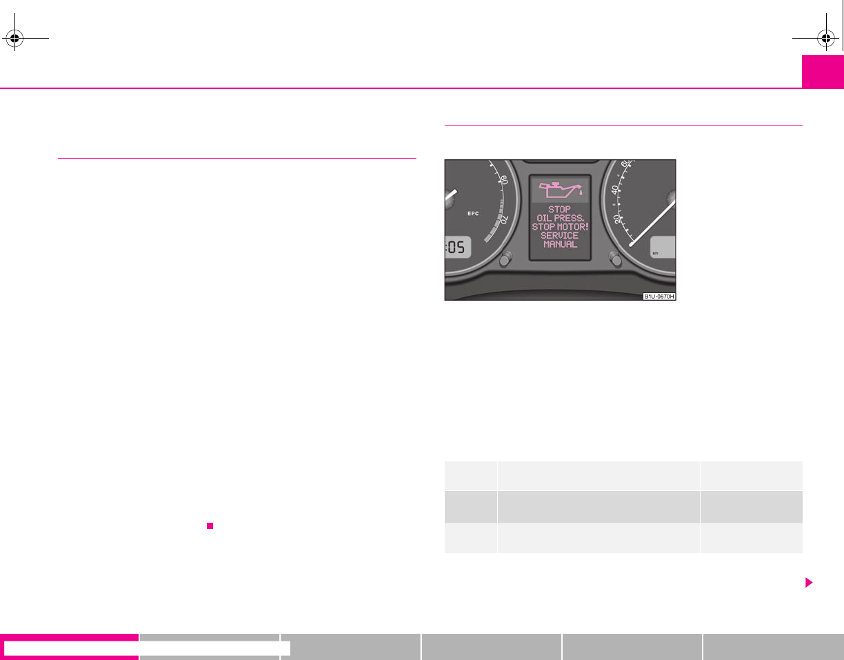
Engine oil
The warning light lights up red (low oil pressure)
The warning light comes on for a few seconds when the ignition is switched on 3).
Stop the vehicle and switch the engine off if the warning light does not go off
within a few seconds after switching on the ignition or flashes while driving. Check
the oil level and top up with oil as necessary ⇒page 163.
3 peeps sound as an additional warning signal.
3) The warning light on vehicles fitted with information display does not come on after
switching the ignition on, but only if a fault exists or the engine oil level is too low.
s2g8.b.book Page 31 Tuesday, April 7, 2009 8:53 AM
Instruments and Indicator/Warning Lights32
Do not continue your journey if for some reason it is not possible under the
conditions prevailing to top up with oil. Keep the engine switched off and obtain
professional assistance from a specialist garage, otherwise it could lead to severe
engine damage.
Do not drive any further if the warning light remains on even if the oil is at the
correct level. Do not run the engine not at idling speed either. Contact the nearest
specialist garage to obtain professional assistance.
The following text will be displayed in the information display*:
STOP! OIL PRESS. STOP MOTOR! SERVICE MANUAL
The warning light lights up yellow* (oil quantity too low)
If the warning light lights up yellow, there is not the correct quantity of oil in the
engine. Check as soon as possible the oil level or top up ⇒page 163 with engine
oil.
A peep sounds as an additional warning signal.
The following text will be displayed in the information display*:
CHECK OIL LEVEL
When opening the bonnet, the warning light goes out. If no engine oil has been
replenished, the warning light will come on again after driving about 100 km.
The warning light flashes yellow* (engine oil level sensor faulty)
A fault on the engine oil level sensor is indicated additionally by an audible signal
and the warning light coming on several times after the ignition has been switched
on.
In this case have the engine inspected without delay by a specialist garage.
The following text will be displayed in the information display*:
OIL SENSOR WORKSHOP!
WARNING
•If you must stop for technical reasons, then park the vehicle at a safe
distance from the traffic and switch off the engine and switch on the hazard
warning light system ⇒page 52.
•The red oil pressure light is not an oil level indicator! One should
therefore check the oil level at regular intervals, preferably after every refu-
eling stop.
Open door*
The warning light comes on, if one or several doors are opened.
The warning light on vehicles fitted with information display comes on when
switching the ignition off. If a door or the boot lid is opened.
The warning light on vehicles fitted with information display goes out after
switching the ignition off.
Antilock brake system (ABS) *
The warning light shows the functionality of the ABS and the Electronic Differ-
ential Lock (EDL)*.
The warning light comes on for a few seconds after the ignition has been switched
on or when starting the engine. The warning light goes out after an automatic check
sequence has been completed.
A fault in the ABS
The system is not functioning properly if the ABS warning light does not go out
within a few seconds after switching on the ignition, does not light up at all or lights
up while driving. The vehicle will only be braked by the normal brake system. Visit
a specialist garage as quickly as possible and adjust your style of driving to take
account of the fault in the meantime since you will not know the extent of the fault
and in how far the effect of the antilock brakes is affected.
Further information about ABS ⇒page 135, “Antilock brake system (ABS)*”.
WARNING (continued)
s2g8.b.book Page 32 Tuesday, April 7, 2009 8:53 AM
Instruments and Indicator/Warning Lights 33
riving Tips General Maintenance Breakdown assistance Technical Data
A fault in the entire brake system
If the ABS warning light comes on together with the brake system warning light
(handbrake must be released), there is a fault not only in the ABS but also in
another part of the brake system ⇒.
Electronic Differential Lock (EDL)*
The EDL is a part of the ABS. A fault in the EDL is indicated by the ABS warning light
in the instrument cluster. Have the vehicle inspected immediately by your
nearest specialist garage.
Models fitted with ESP are equipped with electronic differential lock (EDL).
If a significant fault occurs in the ABS system, a warning signal sounds additionally
(3 peeps).
Further information on the EDL ⇒page 132.
WARNING
•If the brake system warning light comes on together with the ABS
warning light stop the vehicle immediately and check the brake fluid
level in the reservoir ⇒page 167, “Brake fluid”. If the fluid level has dropped
below the MIN marking, do not drive any further - risk of accident! Obtain
professional assistance.
•Pay attention to the following instructions before checking the brake
fluid level and opening the bonnet ⇒page 160, “Working in the engine
compartment”.
•If the brake fluid is at the correct level, the ABS control function has
failed. The rear wheels may then block very rapidly when braking. In certain
circumstances, this can result in the rear end of the car breaking away - risk
of skidding! Drive carefully to the nearest specialist garage and have the
fault rectified.
Traction control system (TCS) *
The warning light comes on for a few seconds when the ignition is switched on.
The warning light flashes when a control cycle is activated while driving.
The warning light will come on and remains on if the TCS is switched off or if there
is a fault in the system.
The fact that the TCS system operates together with the ABS means that the TCS
warning light will also come on if the ABS system is not operating properly.
If the warning light comes on immediately after starting the engine, the TCS
system can be switched off for technical reasons. In this case, the TCS system can
be switched on again by switching the ignition on and off. If the warning light goes
out, the TCS system is fully functional again.
Further information about the TCS ⇒page 133, “Traction control system (TCS)”.
Electronic stability programme (ESP)*
The warning light comes on for a few seconds when the ignition is switched on.
Components of the ESP system also include the Traction Control System (TCS), the
Electronic Differential Lock (EDL) and the Antilock Brake System (ABS).
The warning light flashes when a control cycle is activated while driving.
The warning light will come on and remains on if the ESP is switched off or if there
is a fault in the system.
The fact that the ESP system operates together with the ABS and the EDL means that
the ESP warning light will also come on if the ABS system is not operating properly.
If the warning light comes on immediately after starting the engine, the ESP
system can be switched off for technical reasons. In this case, the ESP system can
be switched on again by switching the ignition on and off. If the warning light goes
out, the ESP system is fully functional again.
Further information on the ESP ⇒page 131, “Electronic stability programme
(ESP)*”.
Note
If the battery has been disconnected and reconnected, the warning light comes
on after switching on the ignition. The warning light must go out after driving a short
distance.
s2g8.b.book Page 33 Tuesday, April 7, 2009 8:53 AM
Instruments and Indicator/Warning Lights34
Alternator
The warning light comes on after the ignition has been switched on. It should go
out after the engine has started.
If the warning light does not go out after the engine has started, or comes on when
driving, drive to the nearest specialist garage. The vehicle battery will be discharged
in this case so switch off all non-essential electrical components.
A peep sounds as an additional warning signal.
Caution
If the warning light comes on when driving and in addition the warning light
(cooling system fault) also comes on in display, you must then stop the car imme-
diately and switch the engine off - risk of engine damage!
Brake system
The warning light comes on for several seconds after the ignition is switched on.
If the warning light stays on when the ignition is switched on or comes on while
driving, there is a fault in the brake system. Visit the nearest specialist garage imme-
diately and have the brake system inspected.
The following text will be displayed in the information display*:
STOP BRAKE FLUID SERVICE MANUAL
3 peeps sound as an additional warning signal.
One should get used to high pedal forces, long braking distances and long free play
of the brake pedal when driving to the next specialist garage.
For further information on the brake system ⇒page 133, “Brakes”.
Handbrake applied
The warning light also comes on if the handbrake is applied. An audible warning
is also given if you drive the vehicle for at least 3 seconds at a speed of more than 5
km/h.
The following text will be displayed in the information display*:
HANDBRAKE ON
WARNING
•Pay attention to the following instructions before checking the brake
fluid level and opening the bonnet ⇒page 160, “Working in the engine
compartment”.
•If the brake system warning light does not go out a few seconds after
switching on the ignition or comes on when driving, stop immediately and
check the brake fluid in the reservoir ⇒page 167, “Brake fluid”. If the fluid
level has dropped below the MIN marking, do not drive any further - risk of
accident! Obtain professional assistance.
Seat belt warning light*
The warning light comes on after the ignition is switched on as a reminder to
fasten the seat belt.
In the event that the driver is not restrained, a warning signal sounds for 6 seconds.
The following text will be displayed in the information display*:
FASTEN SEAT BELT
Further information on the seat belts ⇒page 108, “Seat belts”.
s2g8.b.book Page 34 Tuesday, April 7, 2009 8:53 AM
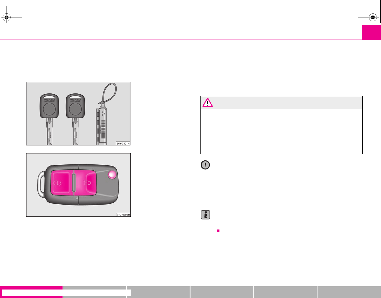
Unlocking and locking 35
riving Tips General Maintenance Breakdown assistance Technical Data
Unlocking and locking
Key
Two keys are provided with the vehicle. Depending on the equipment, your vehicle
can be equipped with keys without radio remote control ⇒fig. 32 or with radio
remote control* ⇒fig. 33.
Key ring
A plastic tag ⇒fig. 32 is attached to one of the keys with the identification of the key.
This identification can be used to order replacement keys from specialist garages.
Carefully store the key ring on which there is the number, because a replacement
key can only be ordered with this number in case the key is lost or damaged. You
should also therefore hand over this key ring to the purchaser when selling the
vehicle.
WARNING
•Always withdraw the key whenever you leave the vehicle - even if it is
only for a short time. This is particularly important if children are left in the
vehicle. The children might otherwise start the engine or operate electrical
equipment (e.g. power windows) - risk of injury!
•Do not withdraw the ignition key from the ignition lock until the vehicle
has come to a stop. The steering lock might otherwise engage unintention-
ally - risk of accident!
Caution
•Each key contains electronic components; therefore protect them against mois-
ture and severe shocks.
•Keep the groove of the keys absolutely clean as impurities (textile fibres, dust
etc.) have a negative effect on the proper operation of the locking cylinder and the
ignition lock.
Note
Please approach a specialist garage if you lose a key since he can obtain a new one
for you.
Fig. 32 Set of keys without
remote control
Fig. 33 Remote control key
s2g8.b.book Page 35 Tuesday, April 7, 2009 8:53 AM
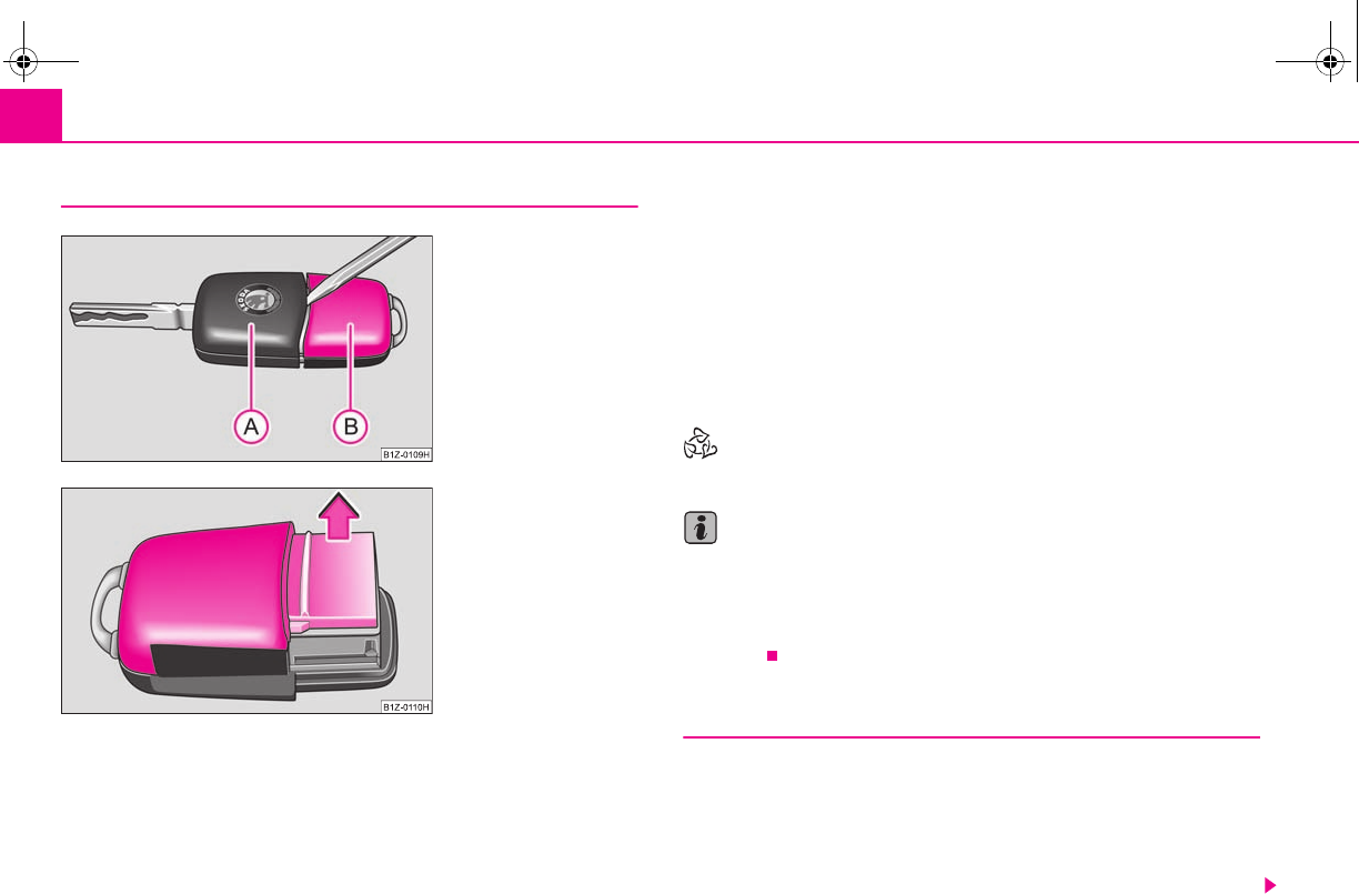
Unlocking and locking36
Changing the battery of the radio remote control
Each remote control key contains a battery which is housed in the cover
of the transmitter housing ⇒fig. 34. We recommend having the
battery of the key replaced by a specialist garage. You should, however,
proceed as follows if you wish to replace the battery yourself:
– Fold open the key.
– Use a thin screwdriver to carefully lever off the front part of the key
⇒fig. 34 from the transmitter housing .
– Take off the cover of the transmitter housing ⇒fig. 35 in direction of
arrow.
– Take the used battery out of the housing cover.
– Insert the new battery. Ensure that the “+” symbol on the battery is
facing downwards. The correct polarity is also shown on the cover of
the transmitter housing.
– Insert cover with battery in place at the rear of the transmitter housing
and press both parts together.
– Insert the transmitter housing into the front part of the key so that the
two parts lock into each other.
For the sake of the environment
Dispose of an old battery in accordance with environmental regulations.
Note
•The replacement battery must have the same specification as the original
battery.
•If it is still not be possible to unlock or lock the vehicle with the remote control
even after replacing the battery this means that the system has to be synchronised
⇒page 42.
Electronic immobiliser
The electronic immobiliser prevents the vehicle being operated by an
unauthorised person.
An electronic chip is integrated in the head of the key. The immobiliser is deacti-
vated with the aid of this chip when the key is inserted in the ignition lock. The elec-
tronic immobiliser is automatically activated when you withdraw the ignition key
from the lock.
Fig. 34 Disconnect key with
radio remote control
Fig. 35 Cover of the trans-
mitter housing
A
B
A
A
A
B
s2g8.b.book Page 36 Tuesday, April 7, 2009 8:53 AM
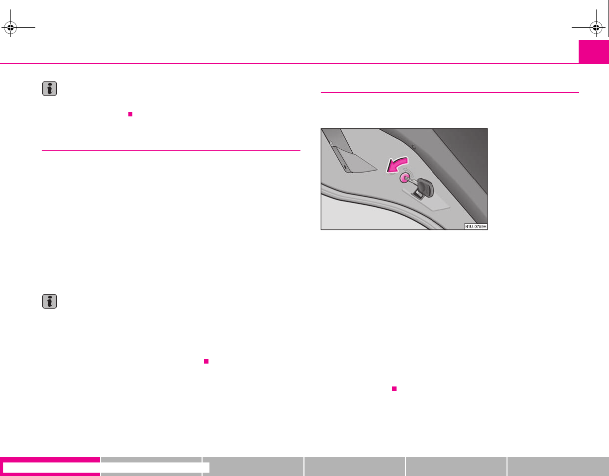
Unlocking and locking 37
riving Tips General Maintenance Breakdown assistance Technical Data
Note
It is only possible to start the engine of your car with a Genuine Škoda key with the
matching code ⇒page 29.
Locking
Valid for vehicles without a central locking system:
Locking from outside
The securing knob will move upwards or downwards in the door when unlocking
or locking.
Locking from inside
All closed vehicle doors are locked by pressing in the securing knobs from the
inside. The doors cannot be opened from the outside when the securing knobs
have been pressed in. The vehicle doors can be opened from the inside as follows:
•the door is unlocked by actuating the door-opening lever;
•The door opens upon actuating the door-opening lever again.
Note
•The opened door cannot be locked with the securing knob. This prevents the
possibility of forgetting the key in the locked vehicle.
•The opened side doors at the rear and the front passenger door are locked by
pressing in the securing knob and slamming the door closed.
•Please refer to the safety guidelines ⇒page 38.
Child safety lock
The child safety lock prevents the rear door from being opened from
the inside.
The rear doors are equipped with a child safety lock. You can switch the
child safety lock on and off using the vehicle key.
Switching child safety lock on
– Use the vehicle key to turn the slit in the rear door to the left in the
direction of the arrow ⇒fig. 36.
Switching child safety lock off
– Use the vehicle key to turn the slit to the right against the direction of
the arrow.
So long as the child safety lock is switched on it is not possible to open the door
from the inside with the door opening lever. In this case the door can be opened
only from the outside.
Fig. 36 Child safety locks on
the rear doors
s2g8.b.book Page 37 Tuesday, April 7, 2009 8:53 AM
Unlocking and locking38
Central locking system*
Description
Unlocking or locking the vehicle causes all doors to be unlocked or locked at the
same time by the central locking system. The boot lid is unlocked when opening. It
can be opened by pressing the hand grip above the licence plate ⇒page 41, fig. 39.
Operation of the central locking system is possible:
•from the outside using the vehicle key ⇒page 39,
•using the button for the central locking system ⇒page 40,
•by using the remote control ⇒page 42.
•with the securing knobs in the doors ⇒page 40, fig. 38 - only for vehicles which
are not fitted with electrically operated power windows (only for locking).
Warning light and securing knobs in the doors
All the securing knobs move upwards when unlocking.
The driver door must be closed when locking. Other doors can also be closed after
locking.
All the securing knobs move downwards when locking. If this is not the case, the
relevant door must be opened once again and properly closed.
The warning light flashes in the driver door, next to the securing knob, to confirm
that the vehicle has been correctly locked. The warning light will not flash if the safe
securing system is deactivated ⇒page 38.
This is not the case, however, for vehicles with an anti-theft alarm system* since the
indicator light is showing that the system is active.
Convenience operation of windows
One can open and close the electrically powered windows when unlocking and
locking the vehicle ⇒page 45, “Window convenience operation”.
Opening a single door*
This function makes it possible to only unlock the driver's door. The other doors
remain locked and are only unlocked when the command is repeated.
If you wish, you can have a specialist garage activate the function of the single door
opening mode.
WARNING
Locking the doors prevents involuntary opening in an exceptional situation
(an accident). Locked doors prevent unwanted entry into the vehicle from
outside, for example at road crossings. Locked doors do, however, make it
more difficult for rescuers to get into the vehicle in an emergency - danger to
life!
Note
•In the event of an accident in which the airbags are deployed, the locked doors
are automatically unlocked in order to enable rescuers to gain access to the vehicle.
•Only the front doors can be unlocked and locked using the key if the central
locking system fails. You can lock or unlock manually the other doors and the boot
lid.
•Emergency locking of the door ⇒page 40.
•After locking the vehicle via the central locking system, optically check if all the
doors have been locked - position of the securing knobs.
Safe securing
The central locking system is equipped with a safe securing system. Locking the
vehicle from the outside causes the door locks to be automatically blocked. It is not
possible to open the doors with the door handle either from the inside or from the
outside. This acts as an effective deterrent for attempts to break into your vehicle.
If you lock the vehicle with a key or a remote control key, you can deactivate the safe
securing system by locking two times within 2 seconds.
The warning light in the driver door will not flash if the safe securing system is deac-
tivated.
This is not the case, however, for vehicles with an anti-theft alarm system* since the
indicator light is showing that the system is active.
s2g8.b.book Page 38 Tuesday, April 7, 2009 8:53 AM
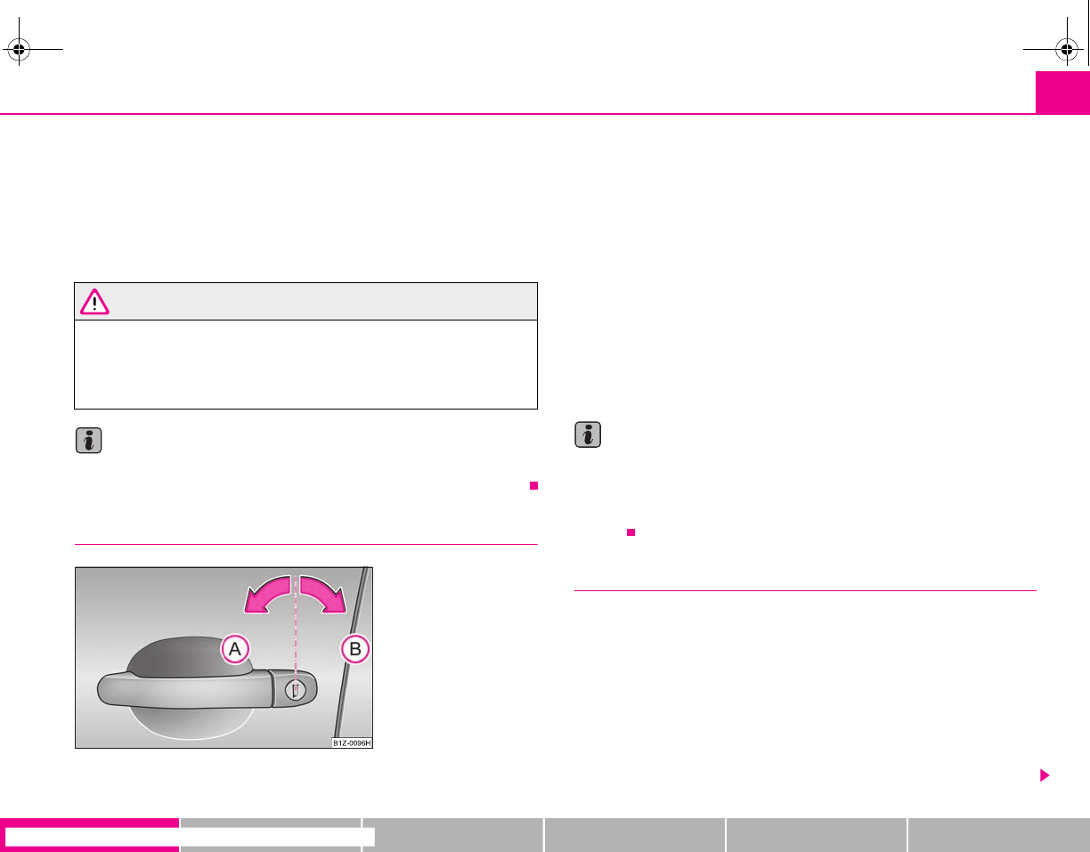
Unlocking and locking 39
riving Tips General Maintenance Breakdown assistance Technical Data
The safe securing system is again activated the next time the vehicle is unlocked and
locked again.
The doors can be opened from the inside if the vehicle is locked and the safe
securing system is deactivated:
•the door is unlocked by actuating the door-opening lever;
•The door opens upon actuating the door-opening lever again.
WARNING
If the vehicle is locked from the outside and the safe securing system is acti-
vated, there must not be any person and animals in the vehicle as it is then
not possible to open either a door or a window from the inside. The locked
doors make it more difficult for rescuers to get into the vehicle in an emer-
gency - hazard!
Note
The anti-theft alarm system* is also activated with the deactivated safe securing
system when locking the vehicle. The interior monitor* is however not activated.
Unlocking the vehicle using the key
– Turn the key in the locking cylinder of the driver's door to the left in the
unlock position ⇒fig. 37.
– Pull on the door handle and open the door.
•All the doors are unlocked.
•The boot lid is then unlocked.
•The switched on interior lights come on over the door contact.
•The safe securing system is deactivated.
•The windows open provided the key is held in the unlock position*. On vehicles
fitted with anti-theft alarm system the window operation is only possible 45
seconds after deactivation of the warning system.
•The indicator light in the driver's door stops flashing if the vehicle is not fitted
with an anti-theft alarm system* ⇒page 43.
Note
If the vehicle is equipped with an anti-theft alarm system*, you must unlock the
vehicle by inserting the key into the driver door you then have to insert the key into
the ignition lock and switch the ignition on within 15 seconds after unlocking the
door. The alarm will be triggered if you do not switch on the ignition within 15
seconds.
Locking the vehicle with the key
– Turn the key in the locking cylinder of the driver's door to the right in
the lock position ⇒fig. 37.
•All the doors and the boot lid are locked.
•The switched on interior lights will switch off over the door contact.
•The windows and the electric sliding/tilting roof* close provided the key is held
in the lock position.
•The safe securing system is activated immediately.
•The indicator light in the driver door begins flashing.
Fig. 37 Turning the key for
unlocking and locking the
vehicle
A
A
A
B
s2g8.b.book Page 39 Tuesday, April 7, 2009 8:53 AM
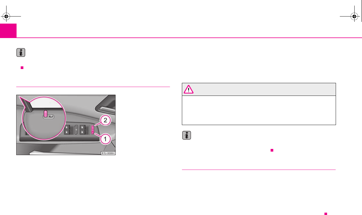
Unlocking and locking40
Note
The opened driver door cannot be locked. It must be locked separately after closing
it.
Button for the central locking system
If the vehicle is not locked from outside, you can unlock and lock the
vehicle with the button in the driver door.
Locking all doors and the boot lid
– Press button ⇒fig. 38. The symbol in the button comes on.
Unlocking all doors and the boot lid
– Press button ⇒fig. 38. The symbol goes out in the button.
The following applies if you have locked your vehicle using the button :
•It is not possible to open the doors or the boot lid from the outside (safety
feature, e.g. when stopping at traffic lights etc.).
•You can unlock the doors individually from the inside and open them by pulling
the door opening lever.
•If the driver door is opened, it cannot be locked; in order to avoid inadvertently
locking the vehicle. You then have to lock the door separately after closing them.
•In the event of an accident in which the airbags are deployed, the locked doors
are automatically unlocked from the inside in order to enable rescuers to gain
access to the vehicle.
WARNING
The central locking system also operates if the ignition is switched off. All the
doors and the boot lid are locked. Children should never be left unattended
in the vehicle since it is difficult to provide assistance from the outside when
the doors are locked. Locked doors make it difficult for rescuers to get into
the vehicle in an emergency - hazard!
Note
The door opening lever and the buttons for the central locking system do not
operate if the safe securing system is activated.
Emergency locking of the doors
Use the securing knobs in the doors for an emergency locking of the
doors ⇒fig. 38.
After closing the door, you can no longer open it from outside. If the child safety
lock is not switched on, it is possible to open the door from the inside by pulling
twice on the door handle. If the child safety lock is switched on, it is necesary to also
open the door from outside besides pulling twice on the inner door handle.
Fig. 38 Button for the central
locking system
A
1
A
2
A
1
s2g8.b.book Page 40 Tuesday, April 7, 2009 8:53 AM
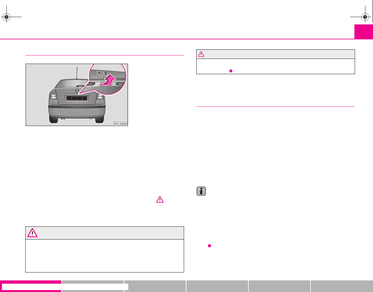
Unlocking and locking 41
riving Tips General Maintenance Breakdown assistance Technical Data
Boot lid
Open the boot lid by pressing the hand grip above the licence plate after
unlocking the vehicle using the key or the radio remote control. On vehi-
cles with central locking*, the boot lid is automatically unlocked and
locked with the other locks.
Opening the boot lid
– Press on the handle ⇒fig. 39 and at the same time raise the boot lid.
Closing the boot lid
– Pull the boot lid down and close it with a slight swing ⇒.
A handle which makes the closing easier is located on the inner paneling of the
boot lid.
WARNING
•Ensure that the lock is properly engaged after closing the boot lid. Other-
wise, the boot lid might open suddenly when driving even if the boot lid lock
is closed - risk of accident!
•Never drive with the boot lid fully opened or slightly ajar otherwise
exhaust gases may get into the interior of the vehicle - risk of poisoning!
•Do not press on the rear window when closing the boot lid, it could crack
- risk of injury!
Remote control*
Description
The vehicle can be unlocked and locked using the radio remote control.
The transmitter with the battery is housed in the handle of the master key. The
receiver is located in the interior of the car. The operating range of the remote
control is approx. 10 m. But this range of the remote control can be reduced if the
batteries are weak.
The master key has a fold-open key bit which can be used for unlocking and locking
the car manually and also for starting the engine.
If a lost key is replaced or if the receiver unit has been repaired or a new unit
installed, it is then necessary for a specialist garage to adapt the system. Only after
this is it possible to again use the remote control.
Note
•The remote control is automatically deactivated when the ignition is switched
on.
•The operation of the remote control may temporarily be affected by interfer-
ence from transmitters close to the car and which operate in the same frequency
range (e.g. mobile phone, TV transmitter).
•The battery must be replaced, ideally by a specialist garage, if the central locking
or anti-theft alarm system does react to the remote control at less than 3 metres
away.
Fig. 39 Handle of boot lid
WARNING (continued)
s2g8.b.book Page 41 Tuesday, April 7, 2009 8:53 AM
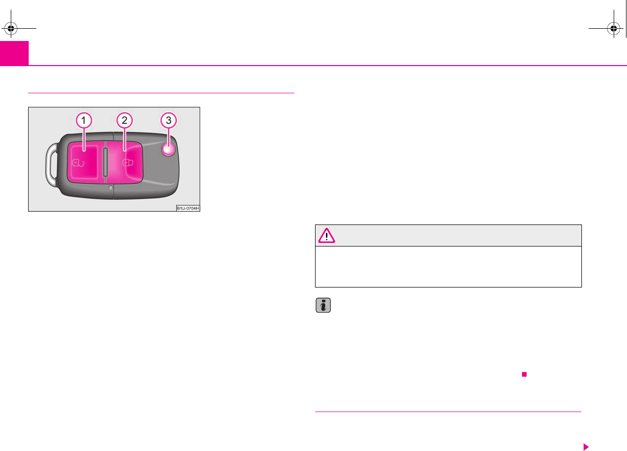
Unlocking and locking42
Unlocking and locking car
Unlocking the vehicle
– Press button for about 1 second.
Locking the vehicle
– Press button for about 1 second.
Deactivating safe securing system
– Press button twice in 2 seconds. Further information ⇒page 38.
Folding out of the key
– Press button .
Folding up of the key
– Press button and collapse the key bit in the housing.
The turn signal lights flash twice as confirmation that the vehicle has been
unlocked. The vehicle will lock again automatically if you unlock the vehicle using
button but do not open a door or the boot lid within the next 30 seconds. This
function is intended to prevent the car being unlocked unintentionally.
The safe securing system along with the anti-theft alarm system are, however,
deactivated during these 30 seconds.
In addition, when the car is unlocked, the electrically adjustable seats and exterior
mirrors* move into the position assigned to this key. The stored setting of driver
seat and exterior mirrors is retrieved.
The turn signal lights flash once to confirm that the vehicle has been correctly
locked. If the turn signal lights do not flash, check the doors, bonnet and boot lid
again to ensure that they are closed. If the doors, the bonnet or the boot lid remain
open when the anti-theft alarm system is activated, the turn signal lights do not
flash until after they have been closed.
When the vehicle is unlocked or locked, the interior lights in the door contact are
automatically switched on or off.
WARNING
If the vehicle is locked from the outside and the safe securing system is acti-
vated, there must not be any person in the vehicle as it is then not possible
to open either a door or a window from the inside. The locked doors make it
more difficult for rescuers to get into the vehicle in an emergency - hazard!
Note
•Operate the radio remote control only when the doors and boot lid are closed
and you have visual contact with the vehicle.
•Once in the car, you must not press the lock button of the radio remote
control before inserting the key into the ignition lock in order to avoid the car being
inadvertently locked and the alarm system* being switched on. Should this
happen, press the unlock button of the radio remote control.
Synchonisation of the remote control
If the vehicle cannot be unlocked by actuating the remote control system then it is
possible that the code in the key and the control unit in the vehicle are no longer
synchronised. This can occur when the buttons on the radio-operated key are actu-
Fig. 40 Folding key with
radio remote control
A
1
A
2
A
2
A
3
A
3
A
1
s2g8.b.book Page 42 Tuesday, April 7, 2009 8:53 AM
Unlocking and locking 43
riving Tips General Maintenance Breakdown assistance Technical Data
ated a number of times outside of the operative range of the equipment or the
battery on the remote control was replaced.
This means it is necessary to synchronise the code as follows:
•Press any button on the remote control.
•pressing of the button means that the door will unlock with the key within 1
minute.
Anti-theft alarm system*
Description
The anti-theft alarm system increases the level of protection against people seeking
to break into the vehicle. The system triggers audible and visual warning signals if
an attempt is made to break into the vehicle.
Optical and acoustic signals alert if an alarm has been triggered (the turn signal
lights flash and the signal horn honks).
How is the alarm system activated?
The anti-theft alarm system is activated automatically when the vehicle is locked
with the key on the closed driver's door or by using the radio remote control. It is
activated 30 seconds after locking the door.
How is the alarm system deactivated?
The anti-theft alarm system is deactivated if the vehicle is unlocked by only using
the radio remote control. The vehicle is automatically locked again if the vehicle is
not opened within 30 seconds after reactivating the anti-theft alarm system.
Once you unlock the vehicle by inserting the key into the driver door you then have
to insert the key into the ignition lock and switch the ignition on within 15 seconds
after unlocking the door in order to deactivate the anti-theft alarm system. The
alarm will be triggered if you do not switch on the ignition within 15 seconds.
When is the alarm triggered?
The following security areas of the locked vehicle are monitored:
•Bonnet,
•Boot lid,
•Doors,
•Ignition lock,
•Vehicle interior 4),
•A drop in voltage of the on-board power supply.
An alarm is immediately triggered if either of the two battery terminals is discon-
nected while the anti-theft alarm system is activated.
Deactivation of interior monitor
The process of switching off and switching on the interior monitoring system is the
same as for switching off and switching on the safe securing system ⇒page 38.
This function makes it possible for example to leave animals in the vehicle.
How is the alarm switched off?
You switch the alarm off if you unlock the vehicle with the radio remote control or
if you switch the ignition on.
Note
•The working life of the alarm siren is 5 years. More detailed information is avail-
able by a specialist garage.
•Before leaving the car, check that all the doors, windows and the electric
sliding/tilting roof* are properly closed in order to ensure that the anti-theft alarm
system is fully operational.
•Coding of the radio remote control and the receiver unit precludes the use of
the radio remote control from other vehicles.
4) The alarm will be triggered through movement of occupants within the interior of the vehicle
or an attempt to steal the radio. The rear part of the interior of the vehicle is not fully moni-
tored under certain circumstances.
s2g8.b.book Page 43 Tuesday, April 7, 2009 8:53 AM
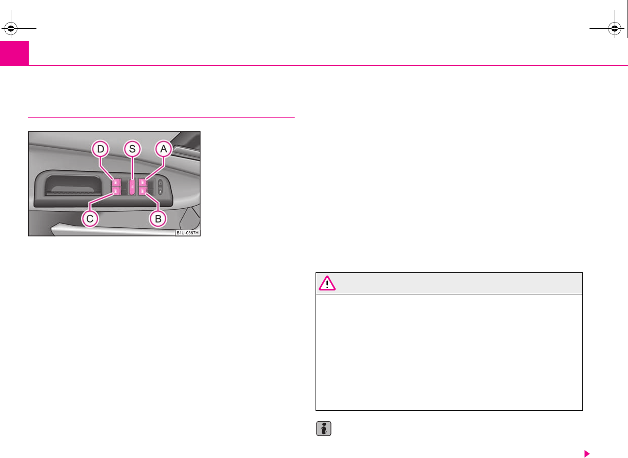
Unlocking and locking44
Power windows*
Buttons on the driver's door
The power windows operate only when ignition is switched on. After
switching the ignition off, the power windows can still be operated
however for maximum 10 minutes if a front door is not opened.
Opening a window
– A window is opened by pressing lightly on the respective button in the
door. The process stops when one releases the button.
– Additionally you can open the window automatically (fully opened) by
pressing the button up to the stop. Renewed pressing of the button
causes the window to stop immediately.
Closing a window
– A window is closed through pulling lightly on the respective button in
the door. The closing process stops when one releases the button.
– Additionally you can close the window automatically (fully closed) by
pulling the button up to the stop. Renewed pulling of the button
causes the window to stop immediately.
The buttons for the individual windows are located in the armrest of the driver's
door ⇒fig. 41, front passenger door and in the rear doors*.
Buttons for the power windows in the armrest for the driver
Button for the power window in the driver's door
Button for the power window in the front passenger's door
Button for the power window in the rear door on the right*
Button for the power window in the rear door on the left*
Safety pushbutton*
Safety pushbutton*
You can deactivate the buttons for power windows at rear doors by pressing the
safety pushbutton ⇒fig. 41. The buttons for power windows at rear doors are
activated again by pressing the safety pushbutton again.
If the buttons for the rear doors are deactivated, the indicator light in the safety
switch lights up.
WARNING
•If you lock the vehicle from the outside, do not leave any person in the
vehicle since it is no longer possible to open the windows from the inside in
an emergency.
•The system is fitted with a force limiter ⇒page 45. If there is an obstacle,
the closing process is stopped and the window goes down into the opened
position. You should then take particular care when closing the windows!
You may otherwise suffer severe injuries as a result of getting an arm, for
example, jammed in the window!
•It is recommended to deactivate the electrically operated power
windows in the rear doors (safety pushbutton) ⇒fig. 41 when children
are being transported on the rear seats.
Note
•Other switches have only two positions for opening and closing the window.
The switch must be held until the window is opened or closed.
Fig. 41 Buttons on the
driver's door
A
A
A
B
A
C
A
D
A
S
A
S
A
S
A
S
A
S
s2g8.b.book Page 44 Tuesday, April 7, 2009 8:53 AM
Unlocking and locking 45
riving Tips General Maintenance Breakdown assistance Technical Data
•After switching the ignition off, it is still possible to open or close the windows
for a further 10 minutes. The automatic window closing will not operate during this
time. The power windows are switched off completely once you open the driver or
front passenger door.
•When driving always use the existing heating, air conditioning and ventilation
system for ventilating the interior of the vehicle. If the windows are opened, dust as
well as other dirt can get into the vehicle and in addition the wind noise is more at
certain speeds.
Button in the front passenger door and in the rear doors
A button for the relevant window is provided in these doors.
Opening a window
– Lightly press the appropriate button down and hold it until the
window has moved into the desired position.
Closing a window
– Lightly press the appropriate button up and hold it until the window
has moved into the desired position.
WARNING
The system is fitted with a force limiter ⇒page 45. If there is an obstacle, the
closing process is stopped and the window goes down. You should then take
particular care when closing the windows! You may otherwise suffer severe
injuries as a result of getting an arm, for example, jammed in the window!
Note
After switching the ignition off, it is still possible to open or close the windows for a
further 10 minutes. The automatic closing and opening functions will not operate
during this time. The power windows are switched off completely once you open
the driver or front passenger door.
Force limiter of the power windows
The electrically operated power windows are fitted with a force limiter. It reduces
the risk of bruises or injuries when closing the windows.
If there is an obstacle, the closing process is stopped and the window goes down
into the opened position.
You must try to close the window once again within 10 seconds after the window
has gone down and if the obstacle was not yet removed, the closing process is
stopped. During this time it is not possible to automatically close the window.
The force limiter is only switched off, if you attempt to close the window within the
next 10 seconds - the window closes now with full strength!
If you wait longer than 10 seconds, the force limiter is switched on again.
WARNING
You should take particular care when closing the windows! You may other-
wise suffer severe injuries as a result of getting an arm, for example, jammed
in the window!
Window convenience operation
You can open and close the electrically powered windows as follows
when unlocking and locking the vehicle (only close the sliding/tilting
roof).
Opening a window
– Hold the key in the locking cylinder of the driver's door in the unlock
position until all the windows are opened.
Closing a window
– Hold the key in the locking cylinder of the driver's door in the lock
position until all the windows are closed.
s2g8.b.book Page 45 Tuesday, April 7, 2009 8:53 AM
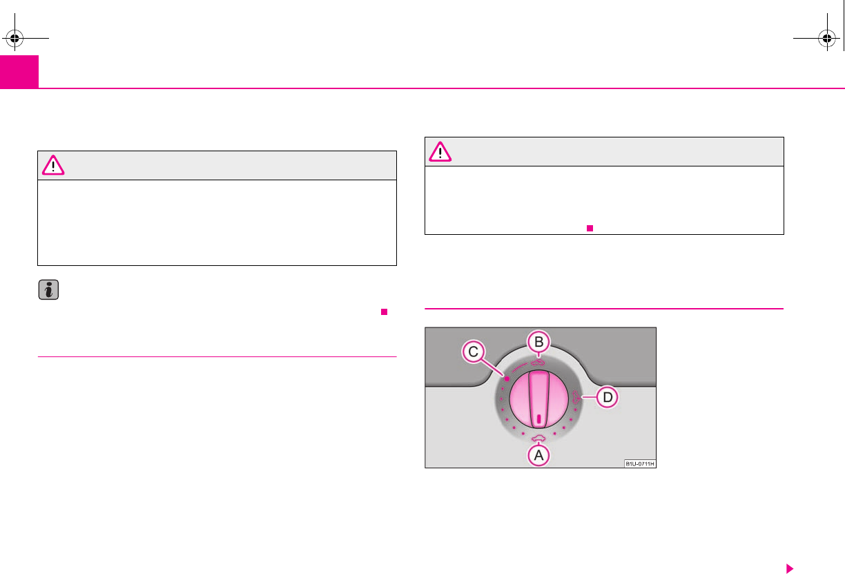
Unlocking and locking46
You can interrupt the opening or closing operation of the windows immediately by
releasing the key.
WARNING
•There must not be any persons in the vehicle which is locked from the
outside. After approx. 10 minutes have expired or after opening and closing
the vehicle door when the ignition is switched off, the windows can no
longer be opened.
•The person who operates the convenience system must take extra care,
when closing the window, that no passengers suffer any injuries.
Note
Obstruction protection is not active during the convenience operating feature.
Operational faults
Electrically operated power windows do not operate
If the battery of the car has been disconnected and then reconnected, the electri-
cally operated power windows do not operate. The system must be activated.
Proceed as follows in order to re-establish the function:
•Hold the key in the locking cylinder of the driver's door in the lock position until
all the windows are closed,
•Release the key,
•Hold the key again in the locking position for about 3 seconds.
Operation in winter
Ice accumulating on the surface of the windows during the winter may result in a
greater resistance when closing the windows and the window may stop and go
down several centimetres
Proceed as follows to close the window fully:
•Hold the key in the locking cylinder of the driver's door in the lock position until
all the windows are closed,
•Repeat this operatiive cycle when the window stops.
WARNING
The system is fitted with a force limiter ⇒page 45. If there is an obstacle, the
closing process is stopped and the window goes down by several centime-
ters. You should then take particular care when closing the windows! You
may otherwise suffer severe injuries as a result of getting an arm, for
example, jammed in the window!
Electric sliding/tilting roof*
Description
The sliding/tilting roof is operated by means of the control dial ⇒fig. 42 and only
functions when the ignition is switched on. The control dial has a number of posi-
tions.
After switching the ignition off, it is still possible to open, close and tilt the
sliding/tilting roof for approx. 10 minutes. It is no longer possible to operate the
sliding/tilting roof after opening one of the front doors, however.
Fig. 42 Control dial for the
power sliding/tilting roof
s2g8.b.book Page 46 Tuesday, April 7, 2009 8:53 AM
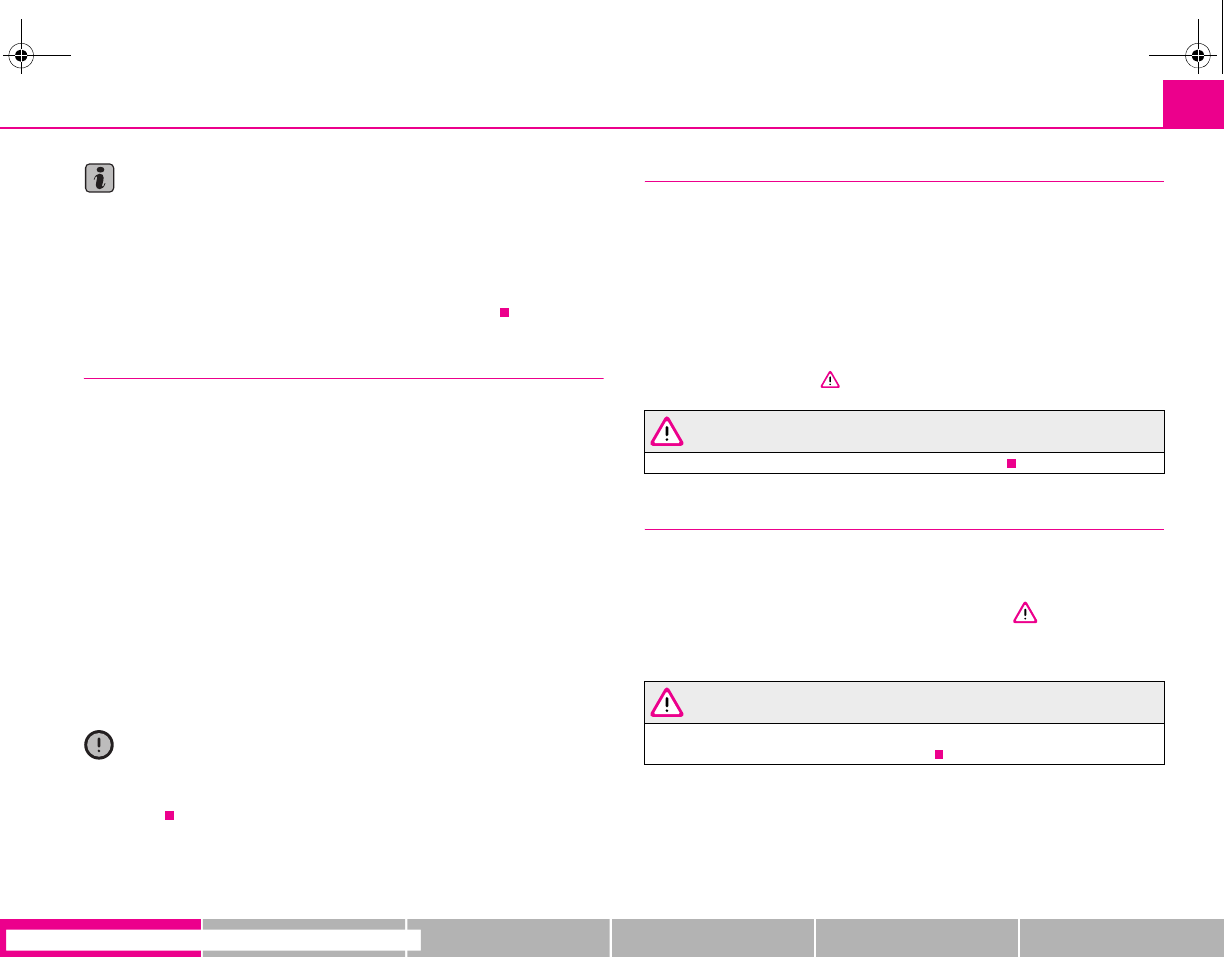
Unlocking and locking 47
riving Tips General Maintenance Breakdown assistance Technical Data
Note
•If the battery has been disconnected and reconnected, it is possible that the
sliding/tilting roof does not close fully. Here you have to set the control dial to the
switch position and press it forward for about 10 seconds.
•It is necessary after each emergency operation (using crank handle) to move the
sliding/tilting roof into the basic position. Here you have to set the control dial to
the switch position and press it forward for about 10 seconds.
Opening and tilting
Comfort position
– Turn the switch to position ⇒page 46, fig. 42.
Opening fully
– Turn the switch to position and hold it in this position (spring-
tensioned position).
Tilting roof
– Turn the switch to position .
The wind noise in the comfort position is less than when the roof is fully opened.
The sun screen is also opened automatically when the roof slides open. You can
slide the sun screen into the opened or closed position by hand when the
sliding/tilting roof is closed.
Caution
It may be necessary during winter to remove any ice and snow in the area of the
sliding/tilting roof before opening it in order to prevent damaging the opening
mechanism.
Closing
Sliding closed/closing the sliding/tilting roof
– Turn the switch to position ⇒page 46, fig. 42.
Safety closing
The sliding/tilting roof is fitted with a force limiter. If an obstacle (e.g. ice) prevents
closing, the sliding/tilting roof stops and opens completely. You can close the
sliding/tilting roof completely without force limiter by pressing the switch to the
position ⇒page 46, fig. 42 at the front for as long as it takes for the sliding/tilting
roof to close completely ⇒.
WARNING
Close the sliding/tilting roof carefully - risk of injury!
Convenience operation
You can also close an open sliding/tilting roof from the outside.
– Hold the key in the locking cylinder of the driver's door in the lock
position until the sliding/tilting roof is closed ⇒.
The closing process stops when one releases the key.
WARNING
Close the sliding/tilting roof carefully - risk of injury! The force limiter does
not operate with the convenience closing.
A
A
A
A
A
C
A
B
A
D
A
A
A
A
s2g8.b.book Page 47 Tuesday, April 7, 2009 8:53 AM
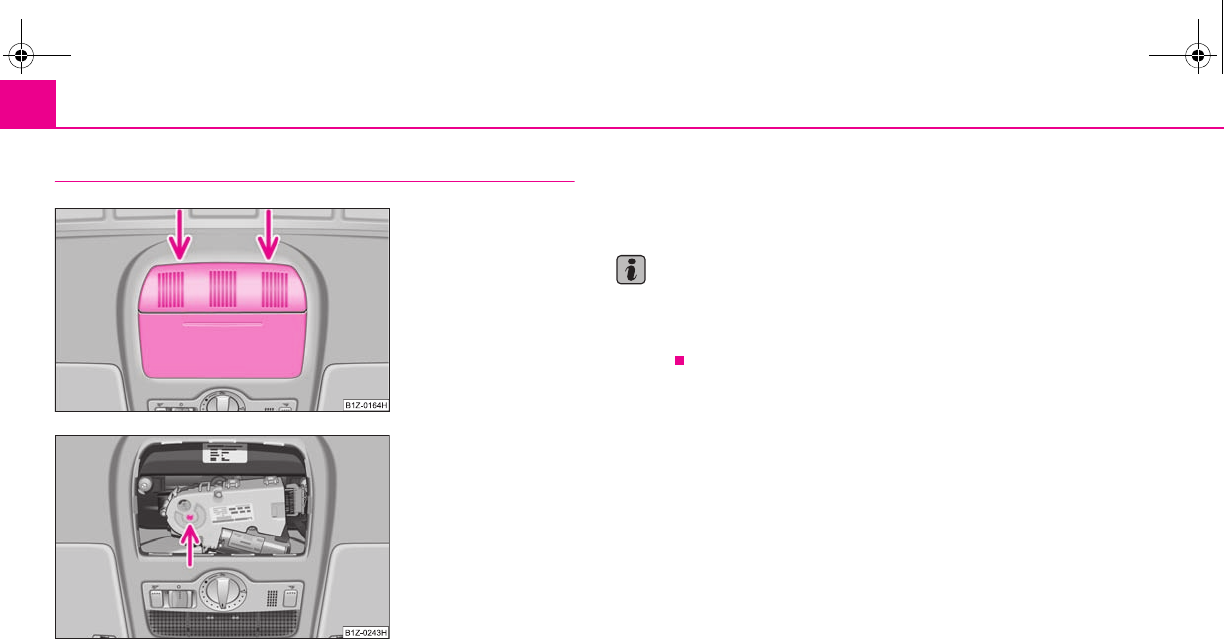
Unlocking and locking48
Emergency operation
You can close and/or open the sliding/tilting roof by hand if the system is
defect.
– Position the flat blade of a screwdriver carefully against the rear edge
of the cover of the electrical drive.
–Pull the cover down ⇒fig. 43.
– Insert an Allen key, Group 4, up to the stop into the opening and close
and/or open the sliding/tilting roof.
– Press on the cover again by first of all inserting the plastic lugs and
then pushing the cover up.
– Have the fault rectified by a specialist workshop.
Note
It is necessary after each emergency operation (using Allen key) to move the
sliding/tilting roof into the basic position. Here you have to turn the control dial
forward to the switch position ⇒page 46, fig. 42 and press for about 10
seconds.
Fig. 43 Detail of the head-
liner: point for positioning
screwdriver
Fig. 44 Detail of the head-
liner: Emergency operation
A
A
s2g8.b.book Page 48 Tuesday, April 7, 2009 8:53 AM
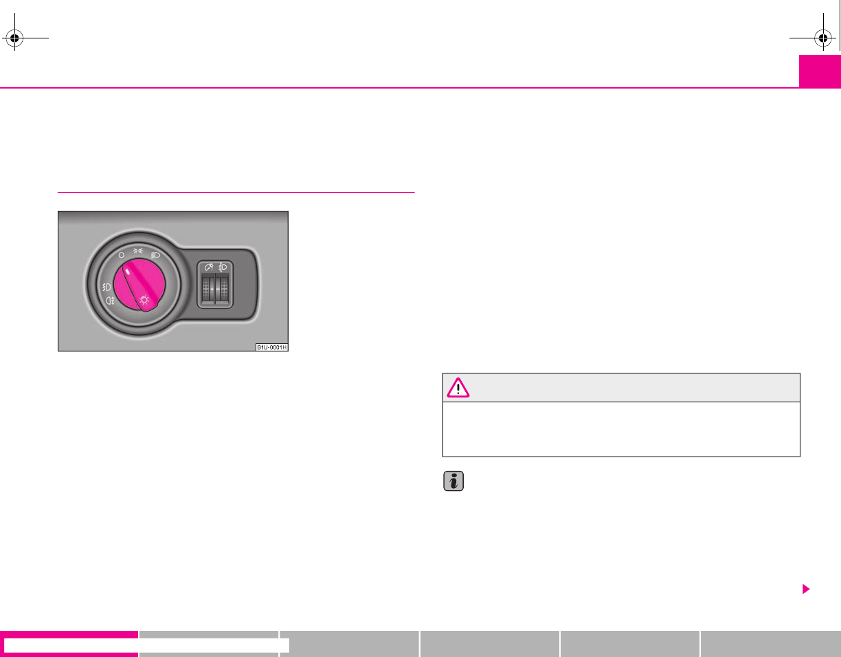
Lights and Visibility 49
riving Tips General Maintenance Breakdown assistance Technical Data
Lights and Visibility
Lights
Switching lights on and off
Switching on side lights
– Turn the light switch into position .
Switching on the low beam and main beam
– Turn the light switch into position .
– Press the main beam lever forward in order to switch on the main
beam ⇒page 52, fig. 50.
Switching off all lights
– Turn the light switch into position°0.
Switching on daylight driving lights*
– Remove the cover of the fuse box on the left side of the dash panel
⇒page 192.
– Insert the activation fuse No. 17 in the fuse box.
Switching off daylight driving lights*
– Remove the cover of the fuse box on the left side of the dash panel
⇒page 192.
– Take the activation fuse No. 17 out of the fuse box.
Low beam comes on only if the ignition is switched on. After switching off the igni-
tion, the low beam is switched off automatically and only the side lights come on.
On models fitted with right-hand steering the position of certain switches differs
from that shown in ⇒fig. 45. The symbols which mark the switch positions are
identical.
In certain countries, the low beam is on a reduced brightness as well as the side
lights, when the ignition is switched on.
WARNING
Never drive with side lights on - risk of accident! The side lights are not
bright enough to light up the road sufficiently in front of you or to be seen by
other oncoming traffic. In this case, always switch on the low beam when it
is dark or if visibility is poor.
Note
•An audible warning will sound if you withdraw the ignition key and open the
driver's door when the vehicle lights are still on.
•The acoustic warning signal is switched off over the door contact when the
driver's door is closed (ignition off). The vehicle can be parked with the side lights
on.
•If the car is parked for a lengthy period, we recommend switching off all lights,
or leaving only the parking lights switched on.
Fig. 45 Dash panel: Light
switch
s2g8.b.book Page 49 Tuesday, April 7, 2009 8:53 AM
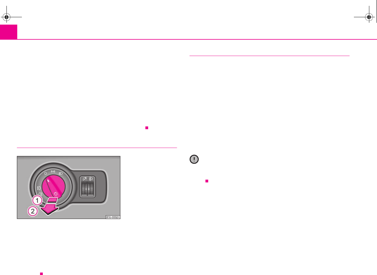
Lights and Visibility50
•The switching on of the described lights should only be undertaken in accord-
ance with the legal requirements.
•If a fault occurs in the light switch, the low beam comes on automatically
•In the event of cool or humid weather conditions, the headlights can be misted
up from inside.
−The temperature difference between interior and external area of the head-
light lenses is decisive.
−When the driving lights are switched on, the light outlet surfaces are free
from mist after a short period. The headlight lenses can possibly mist up at the
border areas.
−It also concerns reverse light and turn signal lights.
−This mist has no influence on the life of the lighting system.
Fog lights*
Switching on the fog lights
– First of all turn the light switch into position or ⇒fig. 46.
– Pull the light switch into position .
If the fog lights are switched on, the symbol next to the light switch is more
brightly illuminated as well as the warning light in the instrument cluster
⇒page 29.
Rear fog light
Switching on the rear fog light
– First of all turn the light switch into position or ⇒fig. 46.
– Pull the switch into position .
If the vehicle is not fitted with fog lights*, the rear fog light is switched on by turning
the light switch to the position and is pulled out directly to the position . This
switch does not have two positions, but only one position.
The rear fog light warning light ⇒page 27 lights up in the instrument cluster
when the fog light is switched off.
Only the rear fog light of the trailer lights up automatically when you are towing a
trailer using a factory-fitted towing device which is fitted with the rear fog light.
The rear fog light is located in the rear light array on the driver's side.
Caution
The rear fog light should only be switched on if visibility is particularly poor
(conform with any varying legal provisions) to avoid dazzling vehicles behind your
vehicle.
Fig. 46 Dash panel: Light
switch
A
1
A
2
A
2
s2g8.b.book Page 50 Tuesday, April 7, 2009 8:53 AM
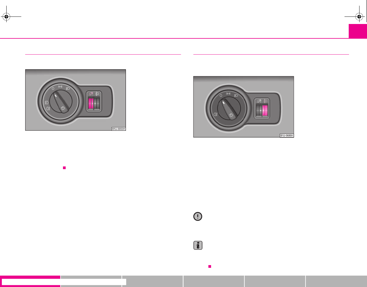
Lights and Visibility 51
riving Tips General Maintenance Breakdown assistance Technical Data
Instrument lighting*
You can adjust the brightness of the instrument lighting.
Instrument lighting
– Switch on the light.
– Turn the control dial ⇒fig. 47 to the desired intensity of the instru-
ment lighting.
Headlamp range adjustment
Once the low beam is switched on you can then adapt the range of
the headlights to the load of the vehicle.
– Turn the control dial ⇒fig. 48 until you have adjusted the low beam
so that oncoming traffic is not dazzled.
Settings
The positions correspond approximately to the following vehicle loads:
Front seats occupied, luggage compartment empty.
All seats occupied, luggage compartment empty.
All seats occupied, luggage compartment laden.
Driver seat occupied, luggage compartment laden.
Caution
Set the headlight beam adjustment in such a way as to avoid dazzling oncoming
traffic.
Note
Headlights fitted with Xenon bulbs adapt automatically to the load and driving state
of the vehicle (e.g. accelerating, braking) when the ignition is switched on and when
driving.
Fig. 47 Dash panel: Instru-
ment lighting Fig. 48 Dash panel: Lights
and Visibility
A
-
A
I
A
II
A
III
s2g8.b.book Page 51 Tuesday, April 7, 2009 8:53 AM
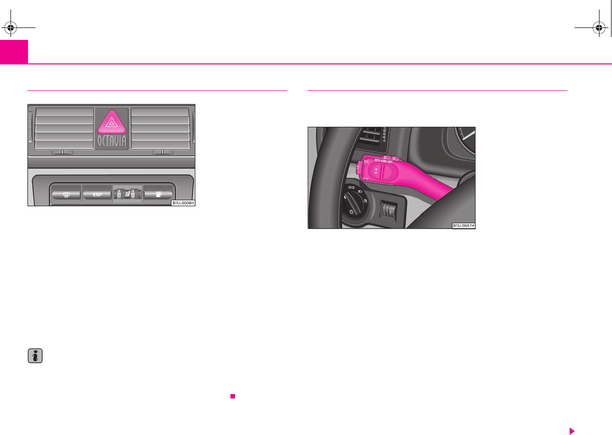
Lights and Visibility52
Switch for hazard warning lights
– Press switch ⇒fig. 49 to switch the hazard warning light system on
or off.
All the turn signal lights on the vehicle flash at the same time when the hazard
warning light system is switched on. The indicator light for the turn signals and the
indicator light in the switch also flash at the same time. You can also switch on the
hazard warning light system if the ignition is switched off.
The hazard warning light system is switched on automatically if an airbag is
deployed in the event of an accident.
Please comply with any legal requirements when using the hazard warning light
system.
Note
Switch on the hazard warning light system if, for example:
•you encounter traffic congestion,
•your vehicle breaks down or an emergency situation occurs.
The turn signal and main beam lever
The parking lights and headlight flasher are also switched on and off
using the turn signal and main beam lever.
The turn signal and main beam lever perform the following functions:
Right and left turn signal light
– Push the lever upwards or downwards ⇒fig. 50.
– Turn signal for changing lanes - in order to only flash briefly, move the
lever up or down to the pressure point and hold it in this position.
Main beam
– Switch on the low beam.
– Push the lever forwards.
– Pull the lever back into the initial position in order to switch the main
beam off again.
Headlight flasher
– Pull on the lever of the steering wheel (sprung position) - the main
beam and warning light in the instrument cluster come on.
Fig. 49 Dash panel: Switch
for hazard warning lights
Fig. 50 Turn signal and main
beam lever
s2g8.b.book Page 52 Tuesday, April 7, 2009 8:53 AM
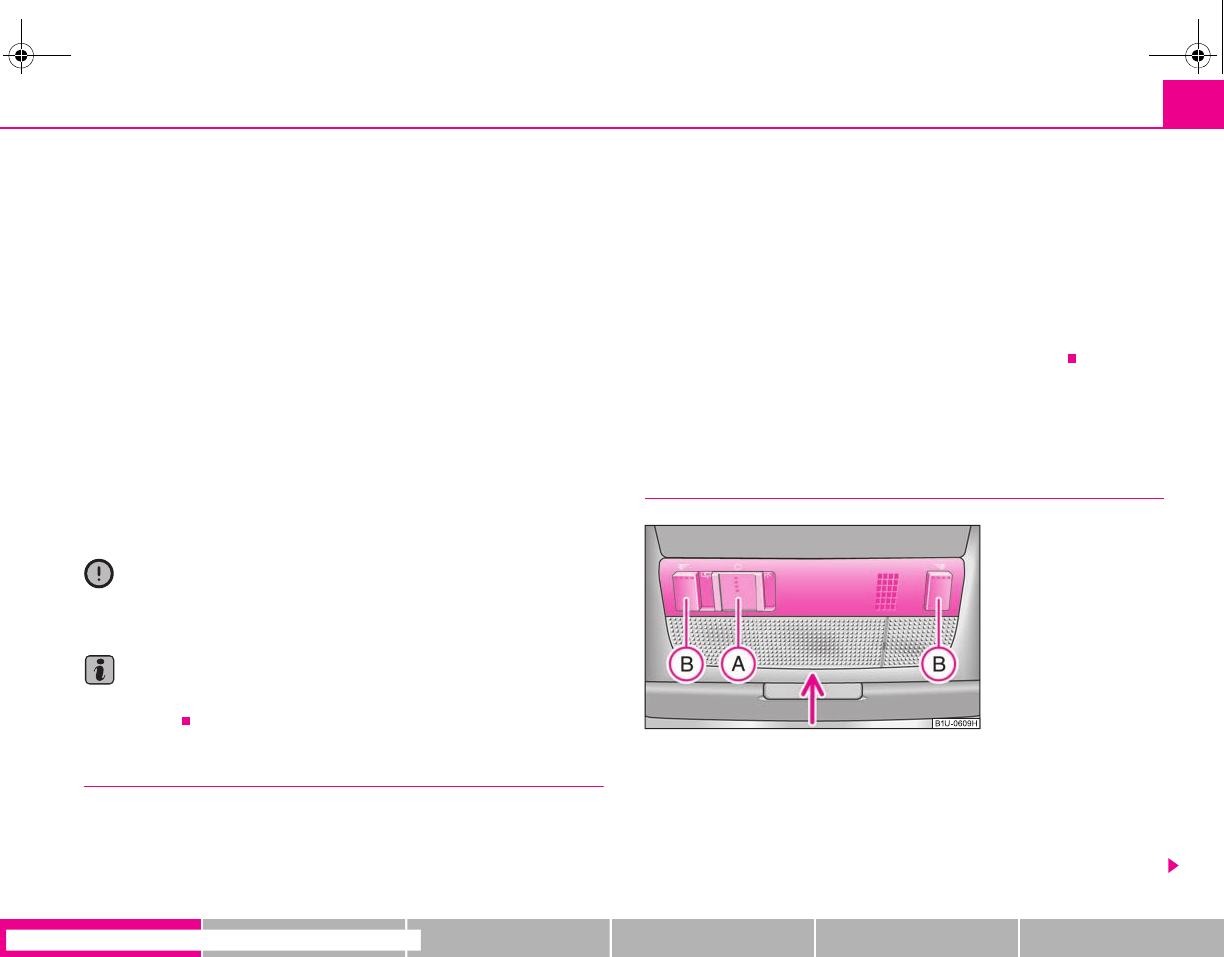
Lights and Visibility 53
riving Tips General Maintenance Breakdown assistance Technical Data
Parking light
– Switch off the ignition.
– Push the lever up or down - the right-hand or left-hand parking light
is switched on.
Information concerning the function of the lights.
•The turn signal system only operates when the ignition is switched on. The
corresponding indicator light or in the instrument cluster also flashes.
•The turn signal is automatically cancelled after negotiating a curve.
•The indicator light flashes at twice its normal rate if a bulb of the turn signal light
fails.
•The side light and rear light on the appropriate side of the vehicle are switched
on when the parking light is selected. The parking light function only operates if
the ignition is switched off.
•An acoustic warning signal will sound when the driver's door is opened if the
lever is not in the middle position after removing the ignition key. The acoustic
warning signal will stop just as soon as the driver's door is closed.
Caution
Use main beam or the headlight flasher only if this does not risk dazzling other road
users.
Note
Use only in accordance with the legal requirements the described lighting and
signal systems.
Coming Home Function*
This function makes it possible to switch on low beam for a short time
after leaving the car, e.g. to illuminate the path to your front door, etc.
Selecting function
– Switch off the light.
– Switch off the ignition.
– Operate the headlight flasher once.
– Open and close the driver door.
If the door remains open, the light remains on for about 3 minutes.
If the door remains closed, the light stays on for about 30 seconds.
Interior lighting
Front interior lighting and lighting of storage compartment on
front passenger side
Switching the interior light on
– Press the switch to the left, the symbol ⇒fig. 51 appears.
Switching the interior light off
– Press the switch into the middle position O.
Fig. 51 Detail of the head-
liner: front interior lighting
A
A
A
A
s2g8.b.book Page 53 Tuesday, April 7, 2009 8:53 AM
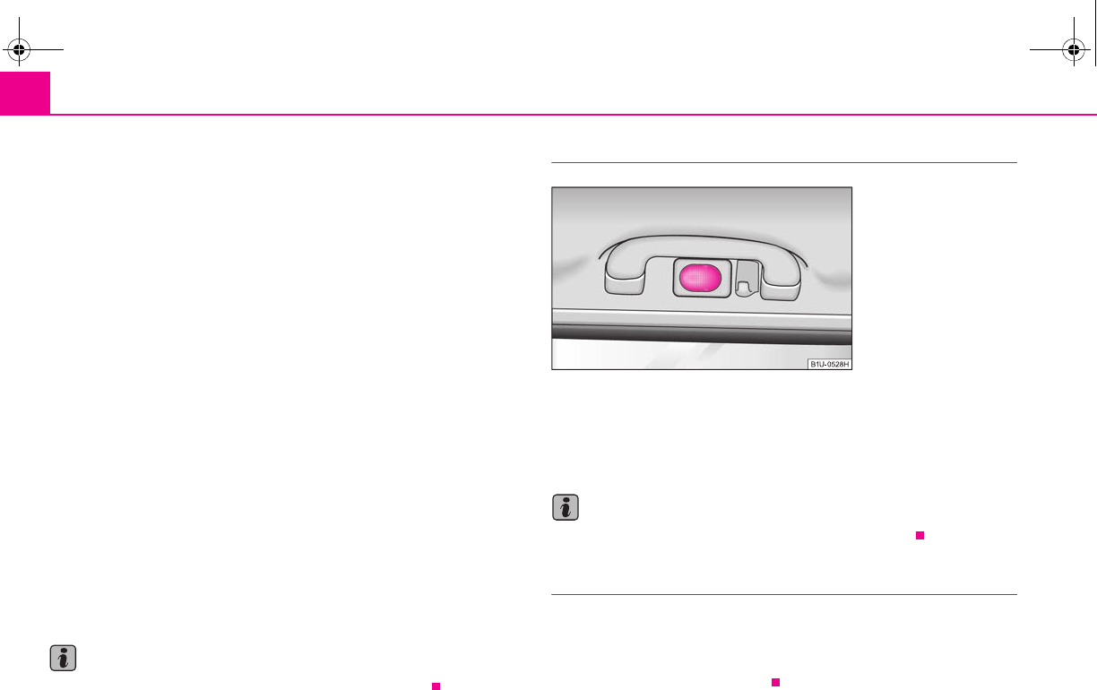
Lights and Visibility54
– On the version without reading lights press the switch to the right,
the symbol O appears.
Door contact switching mechanism (front and rear* doors)
– Press the switch to the right, the symbol appears.
– On the version without reading lights press the switch into the
middle position .
Reading lights*
– Press on one of the switches in order to switch the right or left
reading light on or off.
Lighting of storage compartment on the front passenger side*
– When opening the flap of the storage compartment on the front
passenger side the lighting in the storage compartment comes on.
– The light switches on automatically when the parking light is switched
on and goes out when the flap is closed.
On vehicles with central locking, the interior light is switched on for about 20
seconds when the vehicle is unlocked, when a door is opened or after withdrawing
the ignition key (if the switch of the relevant interior light is in the door contact posi-
tion).
The interior lighting goes off after about 60 minutes when a door has been left open
in order to avoid discharging the battery of the vehicle.
Note
We recommend having these bulbs replaced by a specialist garage.
Rear interior lighting*
The rear interior lighting ⇒fig. 52 is switched on and off by pressing the glass on
the indented point.
The same principles apply for the interior lighting at the rear as for the for the inte-
rior lighting at the front ⇒page 53.
Note
We recommend having the bulb replaced by a specialist garage.
Luggage compartment light*
The light is located at the left top side of the (right - Combi) luggage compartment.
The lighting comes on automatically when the boot lid is opened. The luggage
compartment lighting will switch off again automatically if the boot lid remains
open for more than about 30 minutes.
A
A
A
A
A
A
A
B
Fig. 52 Rear light
s2g8.b.book Page 54 Tuesday, April 7, 2009 8:53 AM
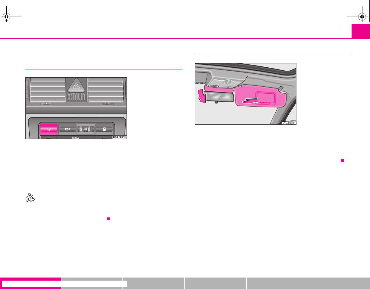
Lights and Visibility 55
riving Tips General Maintenance Breakdown assistance Technical Data
Visibility
Rear window heater
– You can switch the rear window heater on or off by pressing the switch
⇒fig. 53 - the indicator light in the switch comes on or goes out.
You can only activate the rear window heater when the ignition is switched on.
On vehicles with electrically operated power windows, the exterior mirror heater is
also switched on at the same time when the rear window heater is activated.
For the sake of the environment
As soon as the window is de-iced or free from mist, the heating should be switched
off. The reduced current consumption will have a favourable effect on fuel
economy ⇒page 141, “Saving electricity”.
Sun visors
The sun visors can be pulled out of the fixtures and swiveled towards the side
window. The visor above the interior mirror* can only be folded down. ⇒fig. 54.
Sun visors with lighting*
After folding down the visor, the lighting for the vanity mirror is switched on.
Fig. 53 Switch for rear
window heater
Fig. 54 Sun visor: swivelling
out
s2g8.b.book Page 55 Tuesday, April 7, 2009 8:53 AM
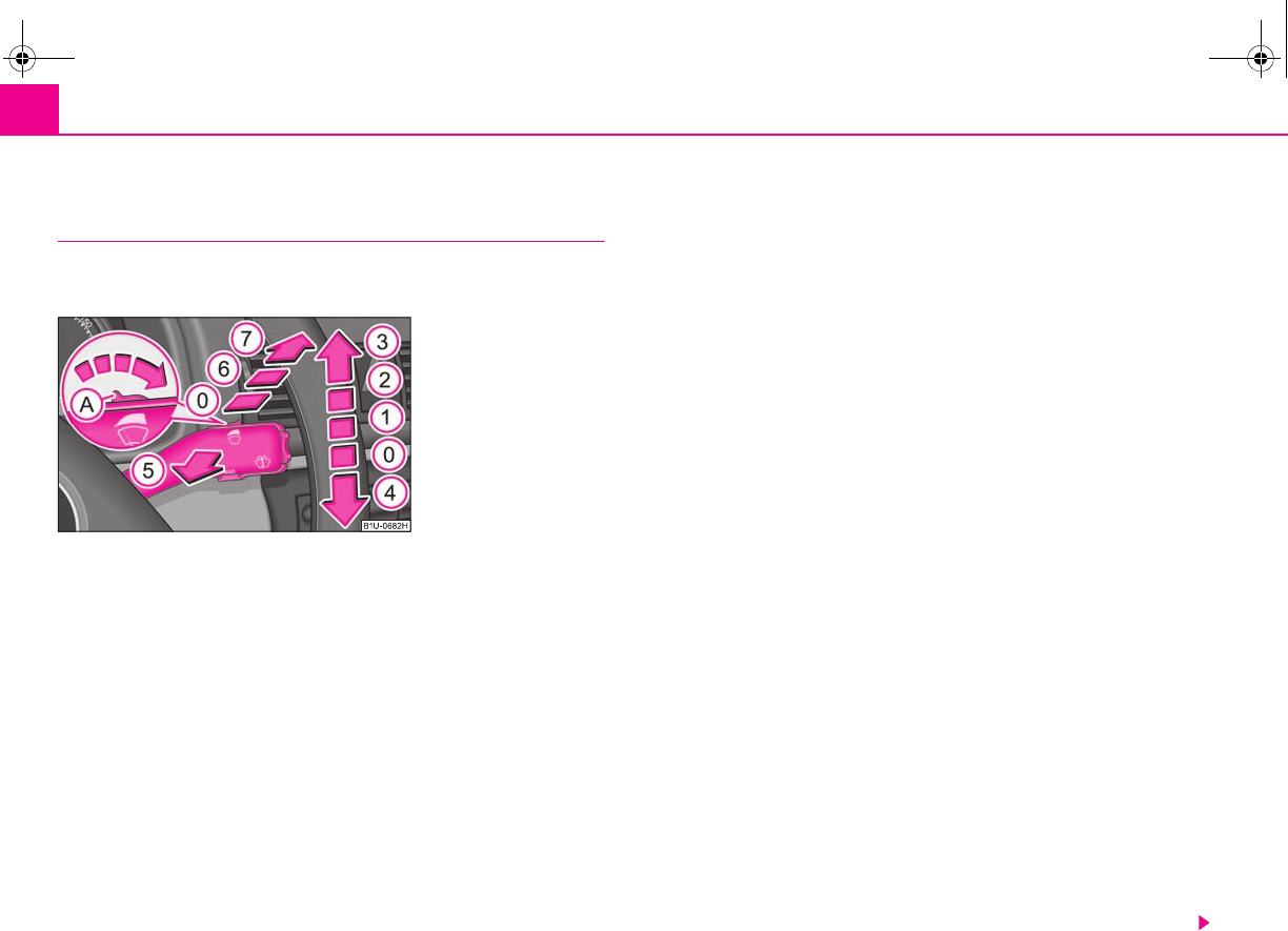
Lights and Visibility56
Windshield wiper and wash system
Windshield wiper
You can operate the windscreen wipers and automatic wipe/wash
using the windscreen wiper lever.
The windscreen wiper lever ⇒fig. 55 has the following positions:
Finger-operated wiping
– If you wish to wipe the windscreen only briefly, push the lever into the
sprung position .
Intermittent wiping
– Position the lever up into position .
– Set with the switch the desired break between the individual wiper
strokes
Slow wipe
– Position the lever up into position .
Fast wipe
– Position the lever up into position .
Automatic wipe/wash for windscreen
– Pull the lever towards the steering wheel into the spring-tensioned
position , the windscreen wiper and wash system will operate
immediately.
– Release the lever. The windscreen wash system stops and the wiper
continues for another 1 - 3 wiper strokes (depending on the period of
spraying of the windscreen).
Rain sensor*
– Move the lever into position .
– You can set the sensitivity of the sensor individually with switch .
– After switching off the ignition, you must then once again activate the
sensor by moving the lever into position , and then back into posi-
tion .
Wiping the rear window pane*
– Push the lever away from the steering wheel into position - the
widescreen wiper will operate every 6 seconds.
Automatic wipe/wash for the rear window pane*
– Push the lever away from the steering wheel into the spring-tensioned
position , the windscreen wiper and wash system will operate. As
long as you hold the lever in this position, the wiper and the wash
system operate - spring-tensioned position.
– Letting go of the lever will cause the windscreen wash system to stop
and the wiper to continue for another 1 - 3 wiper strokes (depending
on the period of spraying of the windscreen). The lever will stay in
position after releasing it .
Fig. 55 Windscreen wiper
lever
A
4
A
1
A
A
A
2
A
3
A
5
A
1
A
A
A
0
A
1
A
6
A
7
A
6
s2g8.b.book Page 56 Tuesday, April 7, 2009 8:53 AM
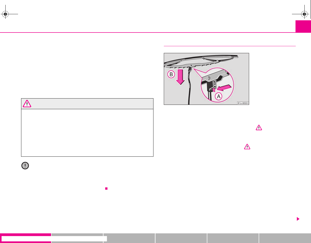
Lights and Visibility 57
riving Tips General Maintenance Breakdown assistance Technical Data
Switching windscreen wipers off
– Move the lever back into its home position .
The windscreen wipers and the windscreen washer system only operate if the igni-
tion is switched on.
The rain sensor* automatically regulates the break between the individual wiper
strokes depending on the intensity of the rain.
The windscreen washer nozzles are heated* when the ignition is switched on.
Top up with wash liquid ⇒page 172.
WARNING
•Properly maintained windscreen wiper blades are essential for clear visi-
bility and safe driving ⇒page 57, “Replacing wiper blades for the wind-
screen wipers”.
•Do not use the windscreen washer system at low temperatures, without
heating the windscreen beforehand. Otherwise the window cleaner could
freeze on the windscreen and restrict the view to the front.
•The rain sensor only operates as a support. The driver is not released
from the responsibility to set the function of the windscreen wipers manu-
ally depending on the visibility conditions.
Caution
In frosty weather, please first of all check whether the windscreen wiper blades are
not frozen to the windscreen before switching them on. Switching on windscreen
wipers when the blades are frozen to the windscreen may result in damage both to
the blades and the motor of the windscreen wipers!
Replacing wiper blades for the windscreen wipers
Taking off the wiper blade
– Fold windscreen wiper arm out from the windscreen and position the
wiper blade at right angles to the wiper arm ⇒.
– Press the securing spring in the direction of arrow and press the
wiper blade at the same time to the windscreen - Warning, danger
of breaking the windscreen. ⇒fig. 56 ⇒.
Attaching a wiper blade
– Clip the securing spring until it is heard to lock in the windscreen wiper
arm.
– Check whether the wiper blade is correctly attached.
Wiper blades in proper condition are essential to obtain good visibility. Wiper
blades should not be allowed to become dirtied by dust, insect remains and
preserving wax.
Juddering or smearing of the wiper blades could then be due to wax residues left
on the windscreen by vehicle washing in automatic vehicle wash systems. It is
therefore important to degrease the lips of the wiper blades after every pass
through an automatic vehicle wash system.
A
0
Fig. 56 Wiper blade for the
windscreen wiper
A
A
A
B
s2g8.b.book Page 57 Tuesday, April 7, 2009 8:53 AM
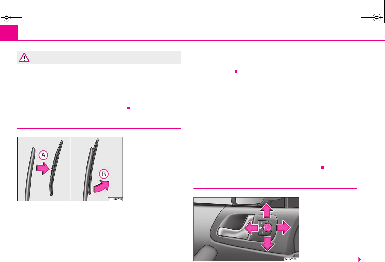
Lights and Visibility58
WARNING
•If the windscreen wipers are handled carelessly, there is a risk of damage
to the windscreen.
•You should clean the wiper blades regularly with a windscreen cleaner in
order to avoid any smears. Clean a wiper blade with a sponge or cloth if it is
very dirty, for example from insect residues.
•Replace the wiper blades once or twice a year for safety reasons. The
wiper blades are available from specialist garages.
Replacing the wiper blade for rear window (Octavia)*
Taking off the wiper blade
– Fold the window wiper arm away ⇒fig. 57.
– Hold the window wiper arm at the top end with one hand.
– Take hold of the wiper blade in the middle with the other hand and
take off the wiper blade by moving in direction of arrow .
Attaching a wiper blade
– Interlock the wiper blade into the window wiper arm - see arrow .
– Check whether the wiper blade is correctly attached.
The same remarks apply here as for ⇒page 57, “Replacing wiper blades for the
windscreen wipers”.
Rear-view mirror
Manual dimming interior rear-view mirror
Adjust the rear mirror before commencing to drive so that there is a clear
view to the rear.
Basic setting
– Pull the lever on the bottom edge of the mirror forward.
Dimming mirror
– Pull the lever on the bottom edge of the mirror back.
Exterior mirror
Fig. 57 Wiper blade for rear
window
A
B
A
A
Fig. 58 Inner part of door:
Rotary knob
s2g8.b.book Page 58 Tuesday, April 7, 2009 8:53 AM
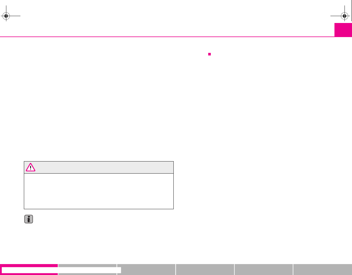
Lights and Visibility 59
riving Tips General Maintenance Breakdown assistance Technical Data
The heating of the external mirror functions only when ignition is
switched on.
Electrically adjustable exterior mirrors*
Carry out the adjustment at the set button next to the inner door handle when the
ignition is switched on ⇒page 58, fig. 58.
Position
Heating of the exterior mirrors (only on vehicles with electrically operated power
windows).
Position L
Operating the left and right mirrors at the same time (valid for vehicles with electri-
cally operated power windows).
Operating the left mirror (valid for vehicles without electrically operated power
windows).
Position R
Operating the right mirror.
WARNING
•Convex (curved outward) or spherical (differently curved) exterior
mirrors increase the vision field. They do, however, make objects appear
smaller in the mirror. These mirrors are only of limited use, therefore, for
estimating distances to the following vehicles.
•Use whenever possible the interior rear mirror, for estimating the
distances to the following vehicles.
Note
•Do not touch the surfaces of the exterior mirrors if the exterior mirror heater is
switched on.
•You can set the exterior mirrors by hand, if the power setting function fails at any
time by pressing on the edge of the mirror surface.
•Contact your specialist garage if a fault exists with the power setting of the exte-
rior mirrors.
s2g8.b.book Page 59 Tuesday, April 7, 2009 8:53 AM
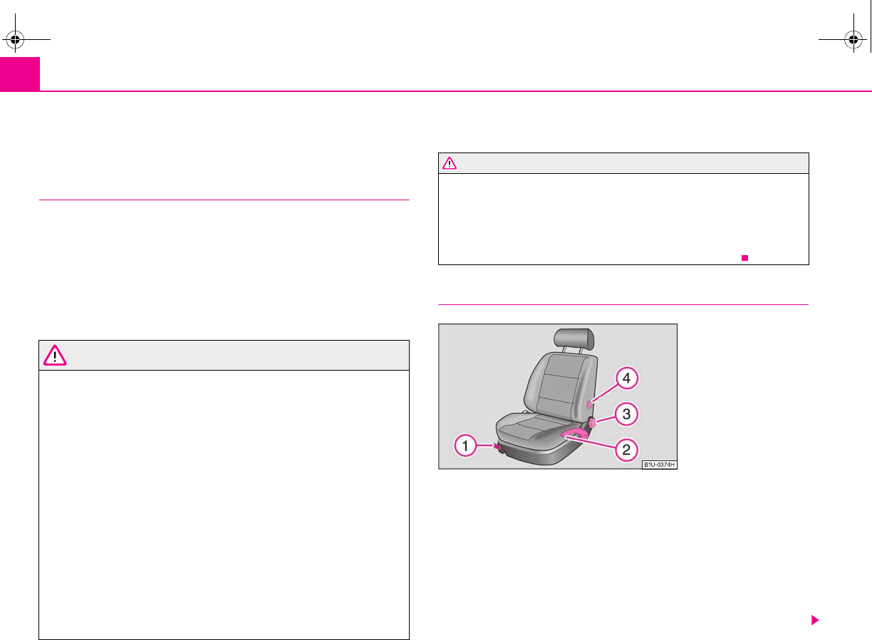
Seats and Storage60
Seats and Storage
Front seats
Basic information
The front seats have a wide range of different settings and can thus be matched to
the physical characteristics of the driver and front passenger. Correct adjustment of
the seats is particularly important for:
•safely and quickly reaching the controls;
•a relaxed, fatigue-free body position;
•achieving the maximum protection offered by the seat belts and the airbag
system.
WARNING
•Never transport more occupants than the maximum seating in the
vehicle.
•Each occupant must correctly fasten the seat belt belonging to the seat.
Children must be fastened ⇒page 123, “Transporting children safely” with
a suitable restraint system.
•The front seats and the head restraints must always be adjusted to match
the body size of the seat occupant as well as the seat belts must always be
correctly fastened in order to provide an optimal protection for you and your
occupants.
•Always keep your feet in the footwell when the vehicle is being driven -
never place your feet on the instrument panel, out of the window or on the
surfaces of the seats. This is particularly important for the front seat
passenger. You will be exposed to increased risk of injury if it becomes
necessary to apply the brake or in the event of an accident. If an airbag is
deployed, you may suffer fatal injuries when adopting an incorrect seated
position!
•It is important for the driver and front passenger to maintain a distance
of at least 25 cm from the steering wheel or dash panel. Not maintaining this
minimum distance will mean that the airbag system will not be able to prop-
erly protect you - hazard! The front seats and the head restraints must
always also be correctly adjusted to match the body size of the occupant.
•Ensure that there are no objects in the footwell as any objects may get
behind the pedals during a driving or braking manoeuvre. You would then
no longer be able to operate the clutch, to brake or accelerate.
Adjusting the front seats
Adjusting a seat in a forward/back direction
– Pull the lever ⇒fig. 59 up and push the seat into the desired posi-
tion.
– Release the lever and push the seat further until the lock is heard
to engage.
Adjusting height of seat*
– Lift the seat if required by pulling or pumping lever upwards.
WARNING (continued)
Fig. 59 Controls at seat
A
1
A
1
A
2
s2g8.b.book Page 60 Tuesday, April 7, 2009 8:53 AM
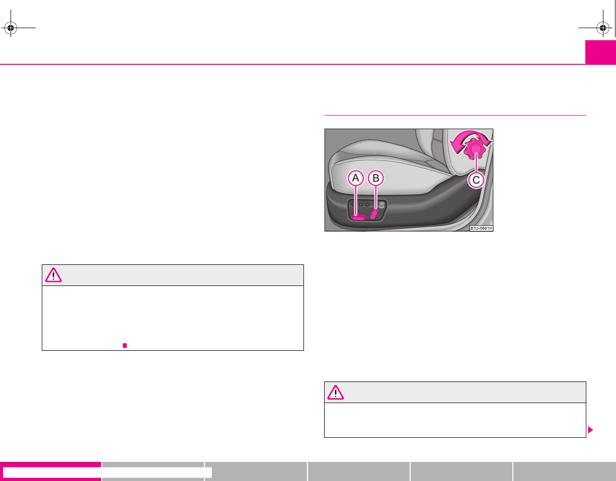
Seats and Storage 61
riving Tips General Maintenance Breakdown assistance Technical Data
– Lower the seat if required by pushing or pumping lever down-
wards.
Adjust the angle of the seat backrest
– Relieve any pressure on the seat backrest (do not lean on it) and turn
the handwheel ⇒page 60, fig. 59 to adjust the desired angle of the
backrest.
Adjusting lumbar support*
– Turn the wheel until you have set the most comfortable curvature
of the seat upholstery in the area of your spine.
The driver's seat should be adjusted in such a way that the pedals can be fully
pressed to the floor with slightly bent legs.
The seat backrest on the driver's seat should be adjusted in such a way that the
upper point of the steering wheel can be easily reached with slightly bent arms.
WARNING
•Only adjust the driver seat when the vehicle is stationary - risk of injury!
•Take care when adjusting the seat! Adjusting the seat without care can
lead to bruises or injuries.
•The seat backrests must not be angled too far back when driving other-
wise this will affect proper operation of the seat belts and of the airbag
system - risk of injury!
Adjusting front seats electrically*
Adjusting seats
Adjusting seat
– Adopt the correct seated position ⇒page 60.
– Press the switch or in the direction of the desired setting
⇒fig. 60.
Adjusting lumbar support
– Adjust the lumbar support mechanically by turning the rotary knob
.
Switch is operated in order to move the seat up/down and forward/back, while
switch is operated in order to move the seat backrest forward or back.
WARNING
•Only adjust the driver seat when the vehicle is stationary - risk of injury!
•Caution when adjusting the seat! You may suffer injuries or bruises as a
result of adjusting the seat without paying proper attention.
A
2
A
3
A
4
Fig. 60 Side view: Controls
for adjusting the seat
A
A
A
B
A
C
A
A
A
B
s2g8.b.book Page 61 Tuesday, April 7, 2009 8:53 AM
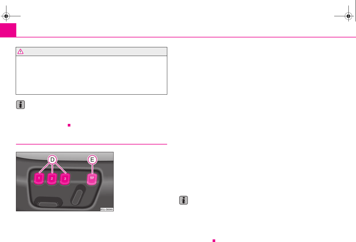
Seats and Storage62
•In view of the fact that the seats can also be adjusted when the ignition is
switched off (even when ignition key withdrawn), you should never leave
children unattended in the vehicle.
•The seat backrests must not be angled too far back when driving other-
wise this will affect proper operation of the seat belts and of the airbag
system - risk of injury!
Note
If the movement of the seat is inadvertently interrupted during an adjustment, once
again press the switch in the appropriate direction and continue with the adjust-
ment of the seat to the end.
Storing setting
Storing seat and exterior mirror settings for driving forward
– Switch on the ignition.
– Adjust the seat ⇒page 61.
– Adjust both exterior mirrors ⇒page 58.
– Press one of the memory buttons and hold the button pressed for
about 3 seconds until an audible signal confirms that the setting has
been stored. The setting of this button was stored.
Storing exterior mirror setting for reversing*
– Switch on the ignition.
– Turn the exterior mirror control to position ⇒page 58.
– Engage the reverse gear.
– Move the right exterior mirror into the desired position ⇒page 58.
– Press one of the memory buttons and hold the button pressed for
about 3 seconds until an audible signal confirms that the setting has
been stored. The setting of the selected button was stored.
The memory system can be deactivated at any time with the button . The seat
and the exterior mirrors can also be manually operated.
Memory buttons
Memory for the seat offers the possibility to store the individual driver seat and
external mirror position. An individual position can be allocated to each of the three
memory buttons ⇒fig. 61, that is three in total. By pressing the appropriate
memory button the seat and external mirror will automatically move into the
position allocated to this button ⇒page 63.
Note
•When storing settings with the memory buttons, we recommend that you begin
with the front button and assign a memory button to each additional driver.
•Each new setting stored with the same button erases the previous setting.
•Each time you store the seat and exterior mirror settings for driving forward you
also have to re-store the individual setting of the exterior mirror on the passenger
side for reversing.
WARNING (continued)
Fig. 61 Driver seat: Memory
buttons and the button MEM
OFF
A
D
A
D
A
E
A
D
A
D
s2g8.b.book Page 62 Tuesday, April 7, 2009 8:53 AM
Seats and Storage 63
riving Tips General Maintenance Breakdown assistance Technical Data
Assigning radio remote control* to the memory buttons
After storing the settings of the seat and exterior mirrors, you have 10
seconds in order to assign the radio remote control to the appropriate
memory button.
– Withdraw the ignition key.
– Press the release button ⇒page 42 and hold it pressed for 1 second
until an audible signal confirms that the setting has been stored. The
setting is stored with the memory button which you have selected.
If you wish to be able to retrieve the settings which are stored in the memory by also
using the radio remote control, you have to assign the radio remote control to a
memory button in each case.
If you wish, you can obtain an additional remote control key from a specialist garage
and then assign the remote control key to another memory button.
Note
•If the radio remote control had previously been assigned to another memory
button, this setting is then erased by the new assignment.
•If you assign the radio remote control to a memory button which has already
been assigned to a radio remote control, the old assignment is also replaced by a
new assignment in this case.
•The assignment of the radio remote control to a memory button is retained,
however, after reassigning the seats and exterior mirrors.
Retrieving seat and exterior mirror settings for driving forward
You can retrieve the stored settings either with the memory button
or also with the radio remote control*.
Retrieving the settings of the seat and mirrors can only be carried out
when the ignition is switched off for safety reasons. Retrieving the
settings can be carried out in two different ways:
Retrieving settings with memory buttons
–By pressing briefly: with the door open, operate the desired memory
button ⇒page 62, fig. 61 with one-touch. The seat and the exte-
rior mirrors now move automatically into the stored position.
–By pressing for a long period of time: with the driver door open or
closed, press and hold the desired memory button until the seat
and the exterior mirrors have moved into the stored position.
Retrieving settings with remote control*
– If the driver door is closed and the ignition is switched off, briefly press
the unlock button of the radio remote control ⇒page 42 and then
open the driver door.
– The seat and exterior mirrors now move automatically into the stored
positions.
Retrieving setting of exterior mirror for reversing*
– Turn the rotary knob for the exterior mirror setting into the position
⇒page 58 before engaging the reverse gear.
Emergency Off
– Press any button on the driver seat.
Note
If the memory button is pressed once again during the automatic setting of the seat
and the exterior mirrors, the setting operation is interrupted. After repeated
pressing of the same button, the setting operation is continued to the end. If one of
the two remaining memory buttons is pressed, the stored setting of this button is
retrieved.
A
D
A
D
A
D
s2g8.b.book Page 63 Tuesday, April 7, 2009 8:53 AM
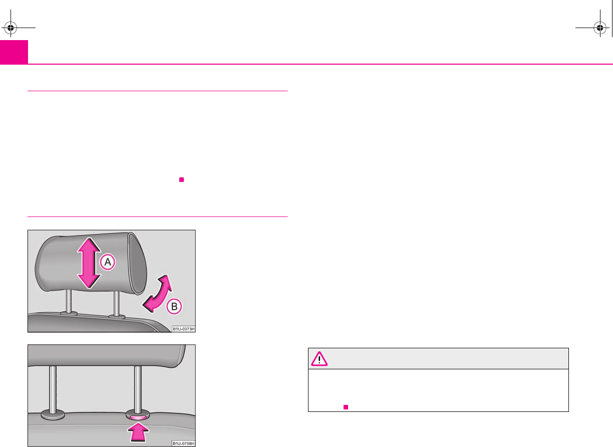
Seats and Storage64
Information concerning the off switch of the memory system
After pressing the off switch of the memory system ⇒page 62, fig. 61, the
memory system is deactivated. You can only adjust the seat and the exterior mirrors
manually. You can switch on the memory system again by once again pressing the
off switch of the memory system. The setting is not carried out to the end if a
retrieved setting operation is interrupted.
We recommend that you switch off the memory system with the off switch if the
vehicle is used for a short period by a driver and you do not wish to store any partic-
ular settings of the seat and mirrors in this case.
Head restraints
Best protection is achieved if the top edge of the head restraint is at the
same level as the upper part of your head.
Adjusting the height of a head restraint
– Grasp the side of the head restraint with both hands and push it up or
down in direction of arrow ⇒fig. 62.
Adjusting the angle of a head restraint
– The head restraint can be matched to the head of the occupant by
adjusting the angle in the direction of the arrow ⇒fig. 62.
Adjusting the angle of the head restraint provides enhanced comfort
for the user.
Removing and installing a head restraint
– Pull the head restraint out of the seat backrest as far as the stop.
– Press the locking button in the direction of arrow ⇒fig. 63 and pull
the head restraint out.
– To re-insert the head restraint, push it down into the seat backrest far
enough until you hear the locking button engage.
The head restraints must be adjusted to match the size of the seat occupant.
Correctly adjusted head restraints together with the seat belts offer effective
protection for the occupants ⇒page 104.
WARNING
•The head restraints must be correctly adjusted in order to offer effective
protection for the occupants in the event of an accident.
•Do not drive under any circumstance with removed head restraints - risk
of injury!
A
E
A
E
A
E
A
E
Fig. 62 Adjusting head
restraint
Fig. 63 Removing a head
restraint
A
A
A
B
s2g8.b.book Page 64 Tuesday, April 7, 2009 8:53 AM
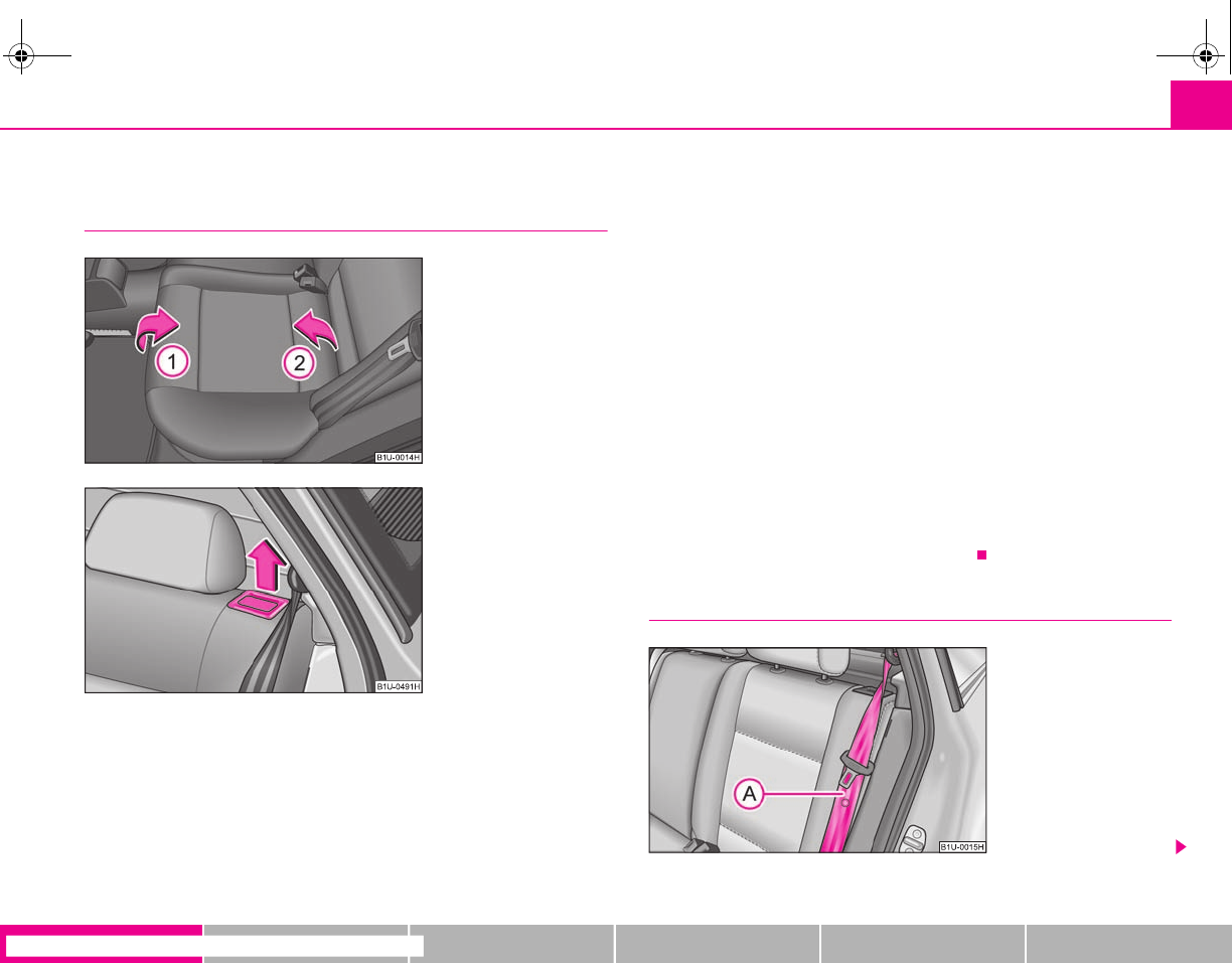
Seats and Storage 65
riving Tips General Maintenance Breakdown assistance Technical Data
Rear seats
Folding the rear seats forwards
The luggage compartment can be increased in size by folding the rear
seats forwards. Before folding the rear seats forwards, it is required to
adapt the position of the front seats and the armrest in such a way that no
mutual deformation or damage can occur to the seats.
Folding seats forwards
– Before folding the rear seats forwards, you must adapt the position of
the front seats in such a way that they are not damaged when the rear
seats are folded forwards.
– Pull up the seat cushion in direction of arrow and fold forwards in
direction of arrow ⇒fig. 64.
– Unlock the seat backrests by pulling the securing knob ⇒fig. 65 and
fold them forwards.
– Remove the head restraints from the seat backrests and fold the back-
rests completely forwards.
– The head restraints can be inserted into the relevant holes of the
folded forward seat cushions.
If the front seats are too far back, we recommend that you have the rear head
restraints removed before the seat backrests are folded forward. Store the removed
head restraints in such a way that they cannot be damaged or soiled. Please refer to
the guidelines ⇒page 68, “luggage compartment”.
Move seats into the initial position
Fig. 64 Folding the seat
cushion forwards
Fig. 65 Unlock the seat back-
rest
A
1
A
2
Fig. 66 Lock the seat back-
rest
s2g8.b.book Page 65 Tuesday, April 7, 2009 8:53 AM
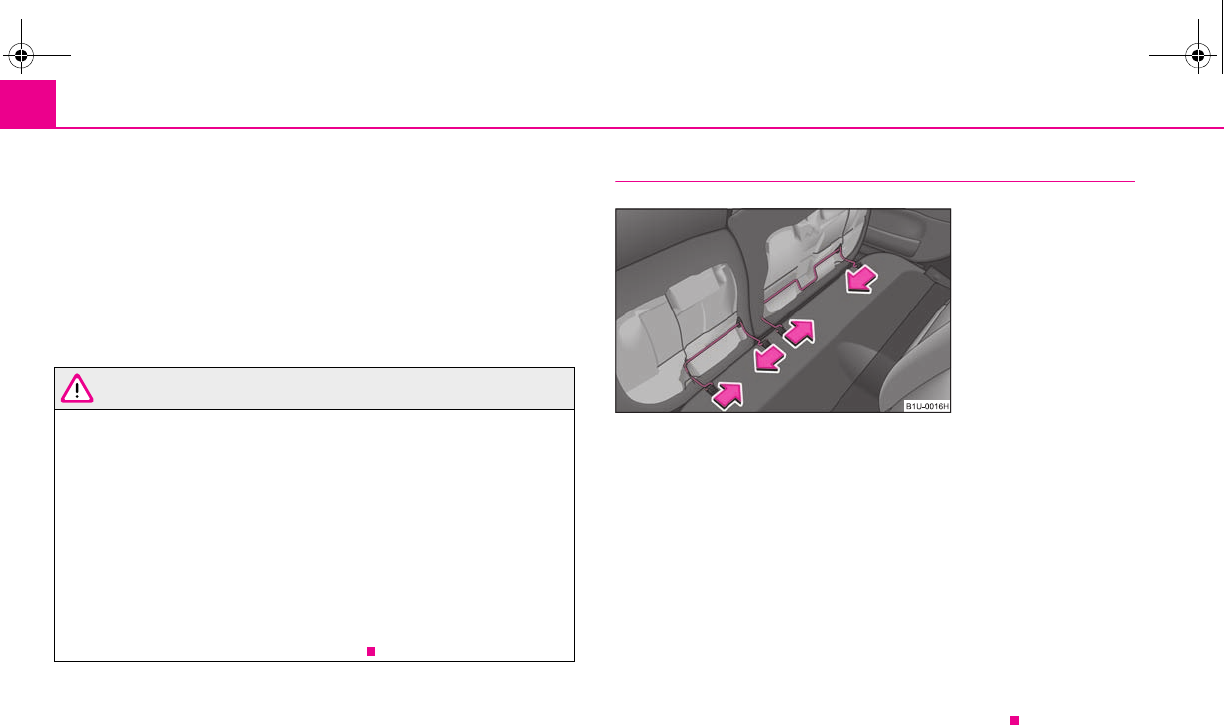
Seats and Storage66
Move seats into the initial position
– Install the head restraints in the slightly lifted seat backrest.
– Place the rear lateral seat belt behind the edge of the side trim
panel ⇒page 65, fig. 66.
– Then push the seat backrest back into the upright position until the
securing knob clicks into place - check by pulling on the seat backrest.
– Move the seat cushion into its original position.
WARNING
•The belts and the belt locks must be in their original position after folding
back the seat cushions and the seat backrests - they must be ready to use.
•The seat backrests must be securely interlocked in position so that no
objects in the luggage compartment can slide into the passenger compart-
ment if there is sudden braking - risk of injury!
•Pay attention that the seat backrests are correctly interlocked. It is only
then that the three-point seat belt for the middle seat can reliably fulfil its
function.
•Before folding the seat backrest back into the secure position, place the
rear lateral seat belt behind the edge of the side trim panel. Take suitable
measures to prevent that the seat belt is jammed between the seat backrest
and the side trim panel and is thus damaged.
Removing the seat cushion
The luggage compartment can be increased further in size by removing
the rear seat.
Removing
– Fold the seat cushion forwards completely.
– Press the wire clamps in the direction of the arrow ⇒fig. 67 and
remove the seat cushion from its holder.
Installing
– Press the wire clamps in the direction of the arrow and place it in its
holder.
– Fold the seat cushion back into its original position.
A
A
Fig. 67 Removing seat cush-
ions
s2g8.b.book Page 66 Tuesday, April 7, 2009 8:53 AM
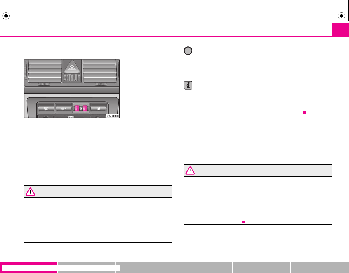
Seats and Storage 67
riving Tips General Maintenance Breakdown assistance Technical Data
Seat heating of the front seats*
You can electrically heat the seat cushions and the seat backrests of the
front seats when the ignition is switched on.
Front seats
– Heating on the driver's and front pasenger's seat can be switched on
and regulated by turning the control dial ⇒fig. 68.
– The system is switched off by turning the control dial to the home
position “0”.
WARNING
If, as an occupant, you have a subdued pain and/or temperature sensitivity,
e.g. through medication, paralysis or because of chronic illness (e.g.
diabetes), we recommend not to use the seat heating. This can lead to burns
on the back, the posterior and the legs which are difficult to heal. If the seat
heating is used, we recommend to make regular breaks in your journey
when driving long distances, so that in specific cases as mentioned above
the body can recuperate from the stress of the journey. Please consult your
doctor, who can evaluate your specific condition.
Caution
•You should not kneel on the seats or otherwise apply pressure at specific points
in order to avoid damaging the heating elements of the seat heaters.
•Do not clean the seats moist ⇒page 152.
Note
•The seat heating should only be switched on when the engine is running. This
has a significant effect of saving on the battery capacity.
•If the on-board voltage drops, the seat heating is switched off automatically, in
order to provide sufficient electrical energy for the engine control.
Pedals
Concerning a secure depressing of the pedal, you should use only footmats from
the Škoda genuine accessories.
Operation of the pedals must not be hindered!
WARNING
•Greater pedal distances may be needed when there is a fault in the brake
system.
•Do not place any footmats or other additional floor coverings in the area
of the pedals in order to ensure that all the pedals can be fully depressed and
are able to return unobstructed to their initial position - risk of accident!
•There must be no objects on the floor which could roll under the pedals.
You would then no longer be able to apply the brakes, operate the clutch or
accelerator - risk of accident!
Fig. 68 Dash panel: Control
dial for heating the front
seats
s2g8.b.book Page 67 Tuesday, April 7, 2009 8:53 AM
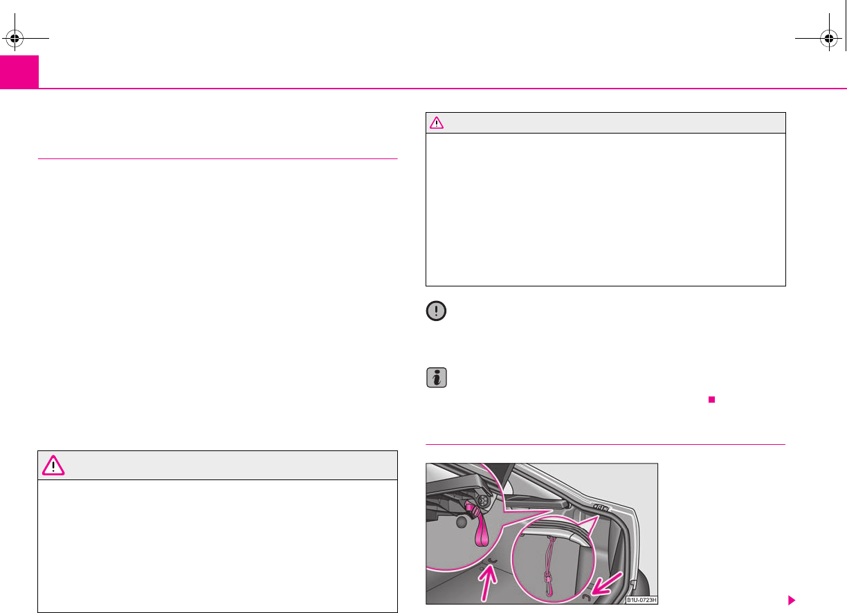
Seats and Storage68
luggage compartment
Loading the luggage compartment
Please observe the following in the interest of having good handling char-
acteristics of your vehicle:
– Distribute the items of luggage as evenly as possible.
– Place heavy objects as far forward as possible.
– Attach the items of luggage to the lashing eyes or the fixing net*
⇒page 68.
In the event of an accident, there is such a high kinetic energy which is produced by
small and light objects that they can cause severe injuries. The magnitude of the
kinetic energy depends on the speed at which the vehicle is travelling and on the
weight of the object. The speed at which the vehicle is travelling is in this case the
more significant factor.
Example: In the event of a frontal collision at a speed of 50 km/h, an unsecured
object with a weight of 4.5 kg produces an energy, which corresponds to 20 times
its own weight. This means that it results in a weight of approx. 90 kg. You can
imagine the injuries that can occur, if this “bullet” is flying through the interior
compartment and hits an occupant.
WARNING
•Store the objects in the luggage compartment and attach them to the
lashing eyes.
•Loose objects in the passenger compartment can be thrown forward
during a sudden manoeuvre or in case of an accident and can injure the
occupants or other oncoming traffic. This risk is still increased, if the objects
which are flying around are hit by a deployed airbag. In this case, the objects
which are thrown back can injure the occupants - hazard.
•Please note that the handling properties of your vehicle may be affected
when transporting heavy objects as a result of the displacement of the
centre of gravity. The speed and style of driving must be adjusted accord-
ingly.
•The items carried in the luggage compartment should be stored in such
a way that no objects are able to slip forward if there are any sudden driving
or braking manoeuvres undertaken - risk of injury!
•Never drive with the boot lid fully opened or slightly ajar otherwise
exhaust gases may get into the interior of the vehicle - risk of poisoning!
•On no account exceed the permissible axle loads and the permissible
gross weight of the vehicle - risk of accident!
•Never transport occupants in the luggage compartment!
Caution
Please ensure that the heating elements of the rear window heater are not
damaged as a result of objects sliding in this area.
Note
Tyre pressure must be adjusted to the load ⇒page 173, fig. 159.
Lashing eyes
WARNING (continued)
Fig. 69 Luggage compart-
ment: Lashing eyes (Octavia)
s2g8.b.book Page 68 Tuesday, April 7, 2009 8:53 AM
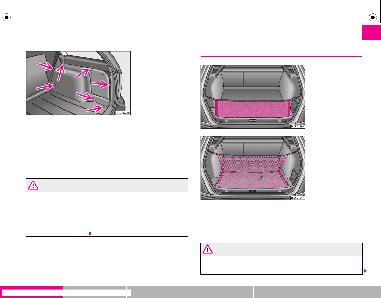
Seats and Storage 69
riving Tips General Maintenance Breakdown assistance Technical Data
You can use the mounts which can be fitted in the openings in the body (Octavia)
⇒page 68, fig. 69 or the mounts for fixing nets (Combi) ⇒fig. 70, the eyes are
located on the luggage compartment floor.
You can also attach a floor fixing net* to these eyes for lashing small objects.
The floor fixing net* together with the installation instruction are stowed in a
container under the floor covering of the luggage compartment behind the spare
wheel.
WARNING
•The load to be transported must be fixed in place in such a way that it
cannot move during the journey and when braking.
•If the items of luggage or objects are attached to the lashing eyes with
unsuitable or damaged lashing straps, injuries can occur in the event of
braking manoeuvres or accidents. In order to prevent the items of luggage
being thrown forward, always use suitable lashing straps which are firmly
attached to the lashing eyes.
Fixing nets - Net programme Octavia*
Fixing examples of the fixing net as double horizontal pocket ⇒fig. 71 and floor net
⇒fig. 72.
The fixing net and the installation instruction are located in a container under the
floor covering of the luggage compartment behind the spare wheel.
WARNING
The whole strength of the net makes it possible to load the pocket with
objects of up to 1,5 kg in weight. Heavy objects are not secured sufficiently -
risk of injury and net damage!
Fig. 70 Luggage compart-
ment: Lashing eyes (Combi)
Fig. 71 Fixing net: Double
horizontal pocket
Fig. 72 Fixing net: double
horizontal pocket, floor fixing
net
s2g8.b.book Page 69 Tuesday, April 7, 2009 8:53 AM
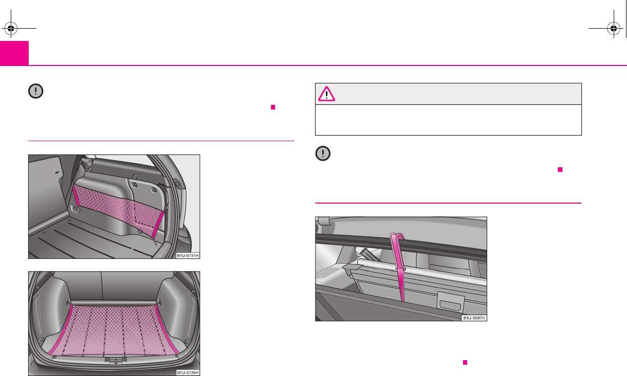
Seats and Storage70
Caution
Do not place any objects with sharp edges in the nets - risk of net damage.
Fixing nets - Net programme Combi*
Fixing examples of the fixing net as double vertical pocket ⇒fig. 73 and floor net
⇒fig. 74.
The fixing net and the installation instruction are located in a container under the
floor covering of the luggage compartment behind the spare wheel.
WARNING
The whole strength of the net makes it possible to load the pocket with
objects of up to 1,5 kg in weight. Heavy objects are not secured sufficiently -
risk of injury and net damage!
Caution
Do not place any objects with sharp edges in the nets - risk of net damage.
Fixing floor covering of the luggage compartment
A plastic hook is located on the handle of the luggage compartment cover. When
handling the spare wheel, you can fix the raised floor covering with the hook on the
frame of the luggage compartment ⇒fig. 75.
Fig. 73 Fixing net: Double
vertical pocket
Fig. 74 Fixing net: Floor net
Fig. 75 Luggage compart-
ment: Fixing of the floor
covering (Combi)
s2g8.b.book Page 70 Tuesday, April 7, 2009 8:53 AM
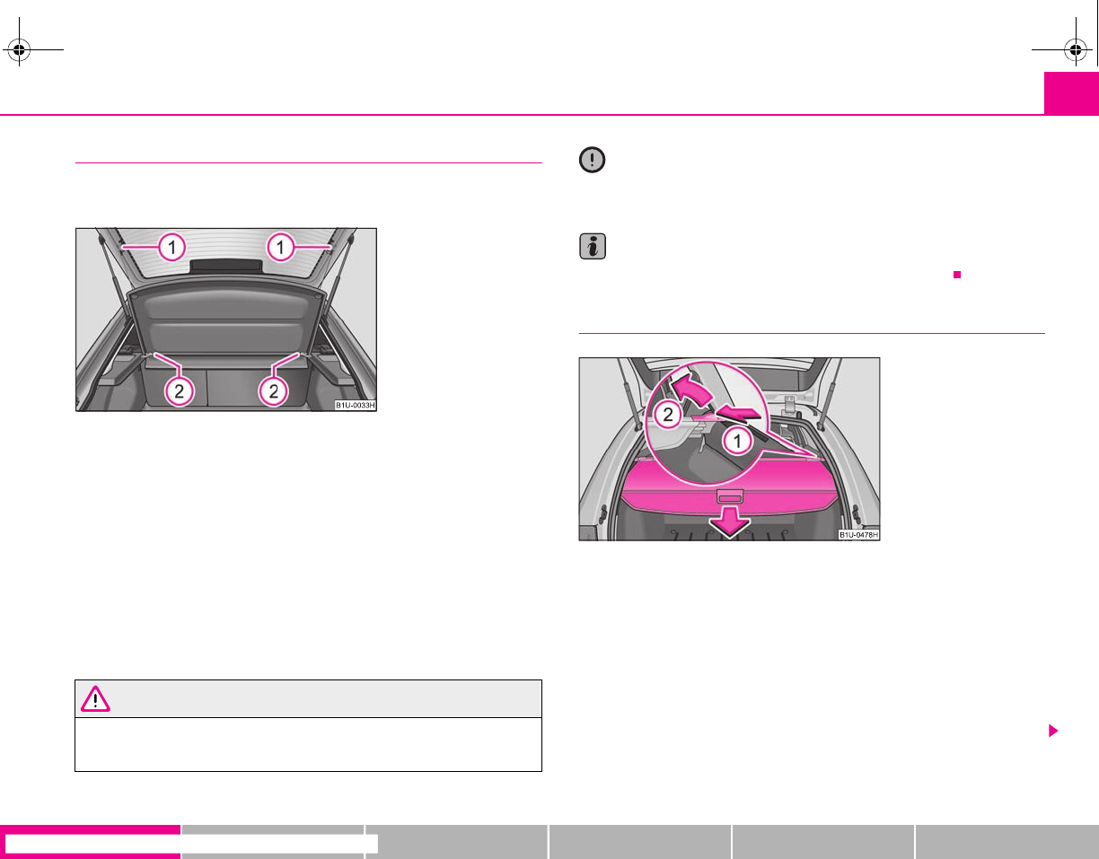
Seats and Storage 71
riving Tips General Maintenance Breakdown assistance Technical Data
Luggage compartment cover (Octavia)
You can use the luggage compartment cover behind the head
restraints for storing light and soft items.
The luggage compartment cover can be removed as required if one must
transport bulky goods.
– Unhook the support straps on the boot lid ⇒fig. 76.
– Place the cover in the horizontal position.
– Pull the cover out of the holder horizontally to the rear.
– Install again by pushing the luggage compartment cover forwards into
the holder and hanging the support straps on the boot lid.
You can stow the removed luggage compartment cover behind the rear seat back-
rest.
WARNING
No objects should be placed on the luggage compartment cover, the vehicle
occupants could be endangered if there is sudden braking or the vehicle
collides with something.
Caution
Please ensure that the heating elements of the rear window heater are not
damaged as a result of objects placed in this area.
Note
Opening the tailgate also lifts up the luggage compartment cover.
Foldable luggage compartment cover (Combi)
Pulling out
– Pull the foldable luggage compartment cover in direction of arrow
⇒fig. 77.
– Hang the luggage compartment cover in the recesses on the side of
the luggage compartment.
Folding
– Pull the foldable cover out of the recesses, the cover is folded up.
Fig. 76 Removing the
luggage compartment cover
A
1
A
2
A
2
A
1
Fig. 77 Luggage compart-
ment: removing the foldable
luggage compartment cover
s2g8.b.book Page 71 Tuesday, April 7, 2009 8:53 AM
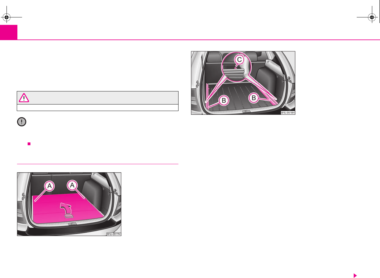
Seats and Storage72
Removing
– Have the foldable luggage compartment cover removed to transport
bulky goods by pressing the slider from the side in the direction of
arrow and removing the cover in the direction of arrow
⇒page 71, fig. 77.
WARNING
No objects should be placed on the luggage compartment cover.
Caution
Please ensure that the heating elements of the rear window heater and the foldable
luggage compartment cover are not damaged as a result of objects placed in this
area.
Variable loading floor* (Combi)
The variable loading floor makes it easier to handle bulky goods and
creates an even luggage compartment floor when the rear seats are
folded forward. The maximum permissable surface load of the variable
loading floor is 75 kg.
Remove variable loading floor
– Unlock the loading floor by turning the locking bolts by approx. 90°
to the left ⇒fig. 78.
– Fold together the loading floor and take it out by moving in direction
of arrow.
Install carrier rails
– Unlock the carrier rails by turning the arbor-mounted fixing eyes
to the right by approx. 90° and take out the carrier rails.
Install carrier rails
– Place the carrier rails in the original position and attach them with
the aid of the mountable fixing eyes by turning to the left by
approx. 90° at the fixed eyes of the body.
Install variable loading floor
– Place the loading floor once folded together onto the carrier rails.
A
1
A
2
Fig. 78 Variable loading
floor
Fig. 79 Luggage compart-
ment: Remove carrier rails
A
A
A
B
A
C
A
B
A
C
s2g8.b.book Page 72 Tuesday, April 7, 2009 8:53 AM
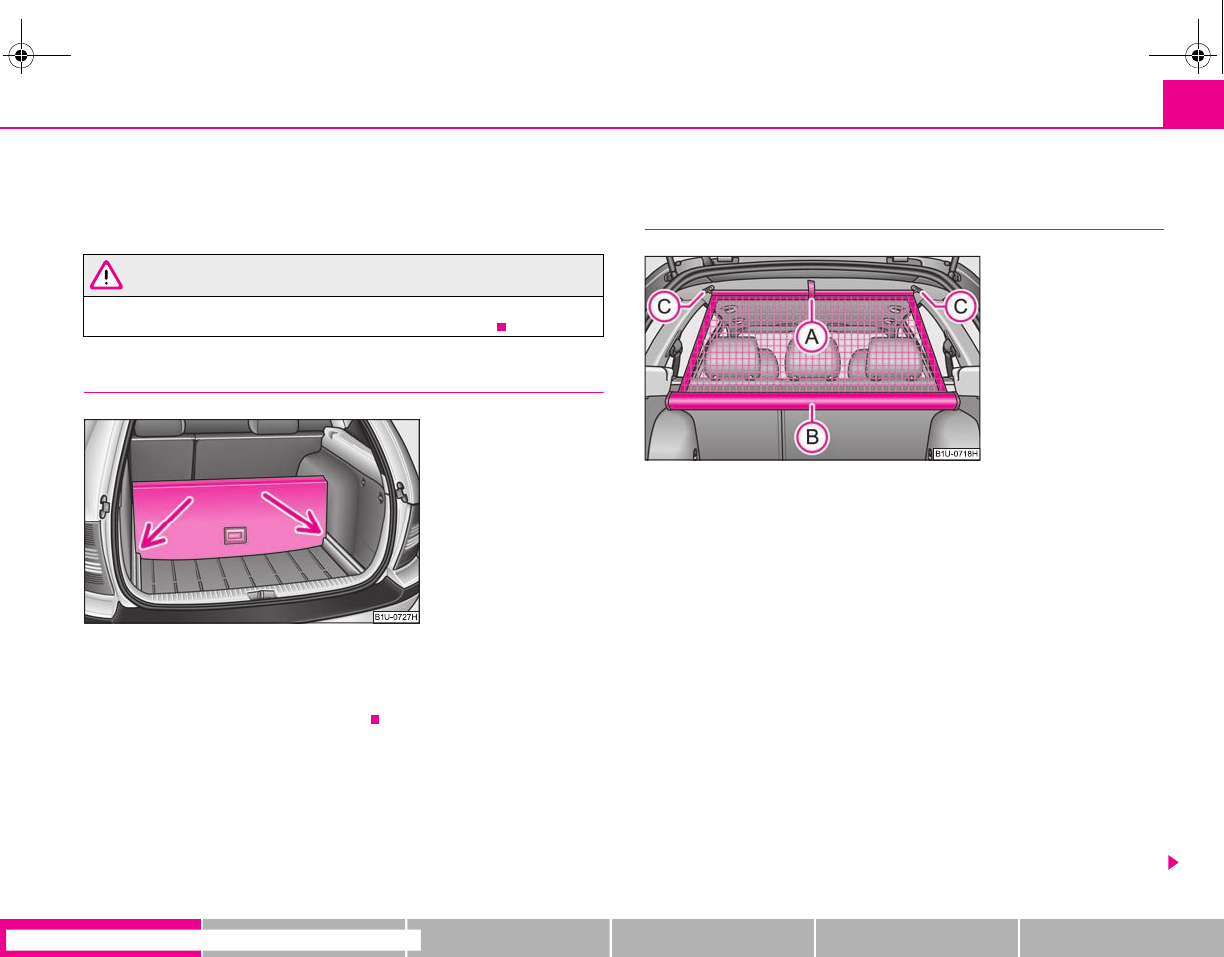
Seats and Storage 73
riving Tips General Maintenance Breakdown assistance Technical Data
– Fold open the loading floor.
– Lock the loading floor by turning the locking bolts by approx. 90°
to the right.
WARNING
Pay attention when installing that the carrier rails and the variable loading
floor are correctly fixed, otherwise the occupants are at risk.
Divide the luggage compartment with variable loading floor*
The luggage compartment can be divided with the variable loading floor.
– Lift up a part of the loading floor with the handle and secure it by
moving it into the grooves ⇒fig. 80.
Net partition (Combi)*
Use the net partition behind the rear seats
The net partition can either be installed behind the rear seats or behind
the front seats. Before using the net partition, remove the foldable cover
⇒page 71.
Pulling out
– Pull the net partition out of the housing at an angle of about 45° in
direction of the boot lid at the loop .
– Insert the cross rod into the mount first on the one side and push
the cross rod forward.
– In the same way, fix the cross rod to the other side of the vehicle,
mount .
Folding
– Push the cross rod first of all on the one side and then on the other
side towards the rear.
– Take the cross rod out of the mounts .
A
A
Fig. 80 Divide the luggage
compartment
Fig. 81 Pull out net partition
A
B
A
A
A
C
A
C
A
C
s2g8.b.book Page 73 Tuesday, April 7, 2009 8:53 AM
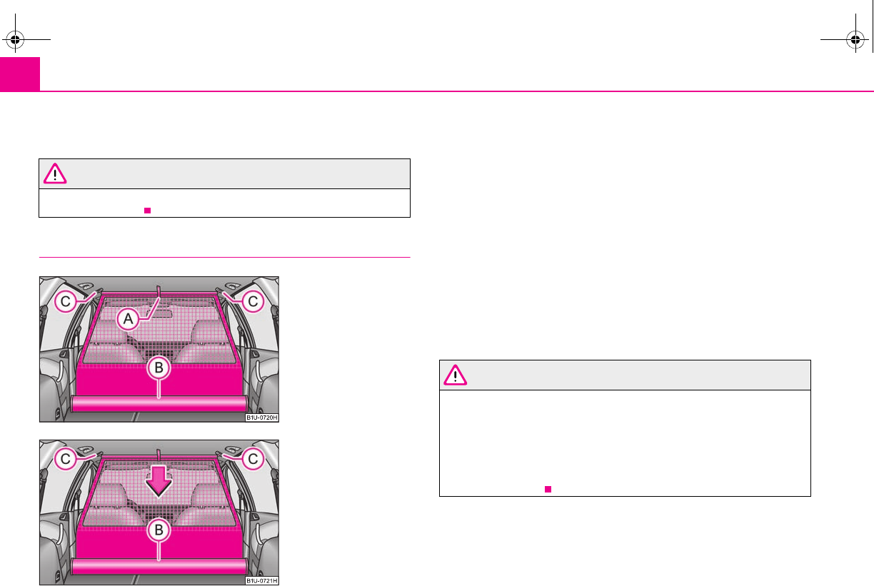
Seats and Storage74
– Roll the net partition at an angle of approx. 45° towards the boot lid in
the housing , so that it does not roll up automatically.
WARNING
•First check for yourself that the cross road is inserted into the mounts
in the front position!
Use the net partition behind the front seats
Pulling out
– Fold the rear seats forwards ⇒page 65
– Pull the net partiton net at the plate out of the housing
⇒fig. 82.
– Insert the cross rod into the mount first on the one side and push
the cross rod forward.
– In the same way, fix the cross rod to the other side of the vehicle,
mount .
Folding
– Pull the cross rod back slightly, first on the one side then on the other
side and take the cross rod out of the mount ⇒fig. 83.
–Hold the cross rod in such a way that the net partition can roll up
slowily and without damage into housing .
– Fold the rear seats back into its original position.
WARNING
•The belt locks and the belts must be in their original position after folding
back the seat cushions and the seat backrests - they must be ready to use.
•The seat backrests must be securely interlocked in position so that no
objects in the luggage compartment can slide into the passenger compart-
ment if there is sudden braking - risk of injury!
•First check for yourself that the cross road is inserted into the mounts
in the front position!
A
B
A
C
Fig. 82 Pull out net partition
Fig. 83 Roll up net partition
A
A
A
B
A
C
A
C
A
C
A
B
A
C
s2g8.b.book Page 74 Tuesday, April 7, 2009 8:53 AM
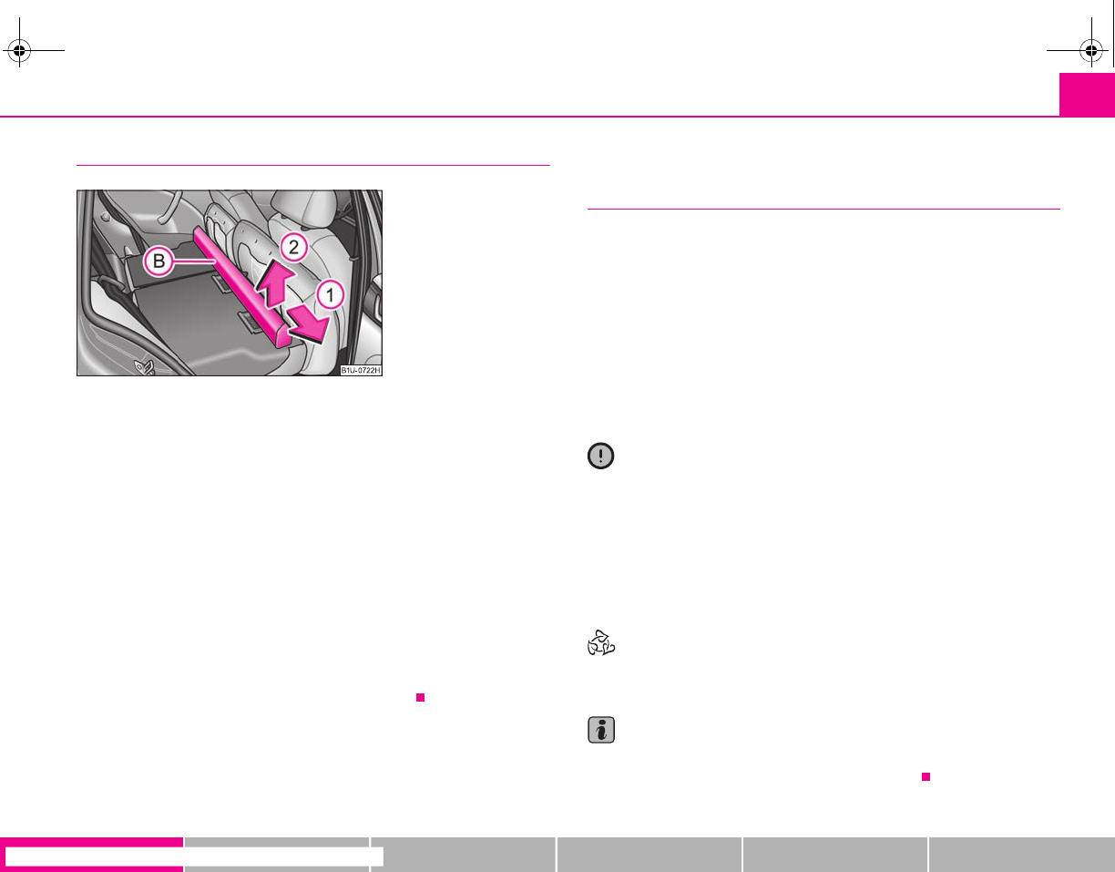
Seats and Storage 75
riving Tips General Maintenance Breakdown assistance Technical Data
Removing and installing net partition housing
Removing
– Fold the rear seats forwards ⇒page 65
– Open the right rear door.
– Push the net partition housing in the direction of arrow up to
the stop and take it out of the mounts of the seat backrest in direction
of arrow .
Installing
– Position the net partition housing into the mounts of the rear seat
backrests.
– Push the net partition housing in the opposite direction of arrow
as far as the stop.
– Fold the rear seats back into its original position.
The roof rack*
Description
Pay attention to the following points if you wish to transport luggage or other items
on the roof of your vehicle:
•A special roof luggage rack system was developed for the vehicle, that is why
you should only use a roof luggage rack which has been released for use by Škoda
Auto.
•The base carrier is the basis for a complete roof luggage rack system. Separate
additional holders are required for safety reasons for transporting luggage, bikes,
surfboards, skis and boats.
•The basic version of the roof luggage rack system and further components are
obtainable as accessories from the specialist garages.
Caution
•If you use other roof rack systems or if the roof bars are not properly fitted, then
any damage which may result to your car is not covered by the warranty agree-
ments. It is therefore essential to pay attention to the fitting instructions supplied
with the roof luggage rack system.
•On models fitted with a power sliding/tilting roof, ensure that the opened
sliding/tilting roof does not strike any items of luggage transported on the roof.
•Ensure that the opened boot lid does not collide with the roof load.
For the sake of the environment
The increased aerodynamic drag results in a higher fuel consumption. One should
therefore take off the roof bar system after use.
Note
A roof rail is obtainable from a specialist garage if hasn't been fitted onto an estate
car at the works, which carries out the professional fitting.
Fig. 84 Rear seats: Net parti-
tion housing
A
B
A
1
A
2
A
1
s2g8.b.book Page 75 Tuesday, April 7, 2009 8:53 AM
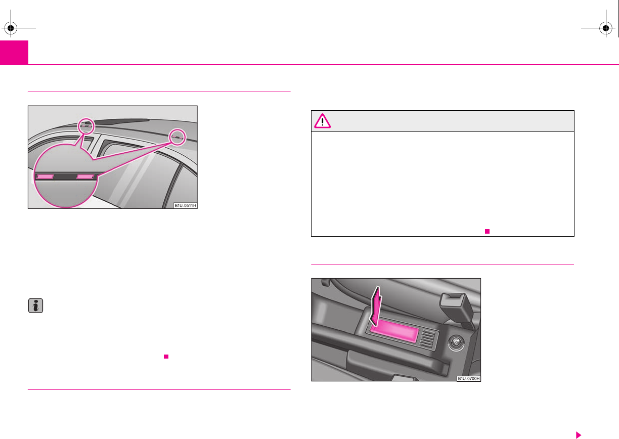
Seats and Storage76
Lashing points (Octavia)
Fitting
– The plastic caps ⇒fig. 85 can be removed by inserting a thin screw-
driver into the recess of the caps and carefully lever out the caps to
avoid paint damage.
– The feet are inserted into the openings of the roof bars.
Note
•Pay attention to the information regarding assembly and disassembly in the
attached instructions.
•If you have any questions, please contact a specialist garage.
•The figure is not valid for an estate car.
Roof load
Distribute weight evenly over the roof luggage rack system. The maximum permis-
sible roof load (including roof rack system) of 75 kg and the maximum permissible
total weight of the vehicle should not be exceeded.
You cannot make full use of the permissible roof load if you use a roof luggage rack
system with a lower load carrying capacity. The load transported on the roof
luggage rack system must not exceed the weight limit which is stated in the fitting
instructions.
WARNING
•The items which you transport on the roof bar system must be reliably
attached - risk of accident!
•You must on no account exceed the permissible roof load, the permis-
sible axle loads and the permissible gross weight of your vehicle - risk of
accident!
•Please note that the handling properties of your vehicle change when
you transport heavy or bulky items on the roof bar system as a result of the
displacement of the centre of gravity and the increased wind attack area -
risk of accident! You must absolutely adapt your style of driving and the
speed of the vehicle to the specific circumstances.
Cup holder in front centre console
After pressing in direction of arrow, the cup holder slides out and opens up
⇒fig. 86.
It is designed to place drink cans or other beverage packagings in (with a content of
0.33°ltr. or 0.5°ltr.).
Fig. 85 Attachment points
for base roof carrier
Fig. 86 Front centre console:
Cup holder
s2g8.b.book Page 76 Tuesday, April 7, 2009 8:53 AM
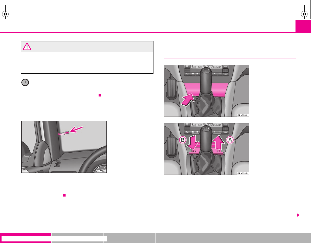
Seats and Storage 77
riving Tips General Maintenance Breakdown assistance Technical Data
WARNING
•Do not place any hot beverages into the cup holder. If the vehicle moves,
the hot beverages may spill - risk of scalding!
•Do not use any cups or beakers which are made of brittle material (e.g.
glass, porcelain). You might be injured by them in the event of an accident.
Caution
Do not open the beverages in the cup holder while driving. They may spill when
braking and while doing so damage the vehicle.
Note holder
The note holder is designed e.g. for attaching a car park ticket in parking areas.
The attached note has to always be removed before starting off in order not to
restrict the driver's vision.
Ashtray*
Front ashtray
Opening ashtray
– Press on the bottom part of the cover of the ashtray at the point of the
arrow ⇒fig. 88.
Removing ashtray insert
– Remove the ashtray insert in direction of arrow .
Fig. 87 Windscreen: Note
holder
Fig. 88 Centre console: Front
ashtray
Fig. 89 Remove ashtray and
replace
A
A
s2g8.b.book Page 77 Tuesday, April 7, 2009 8:53 AM
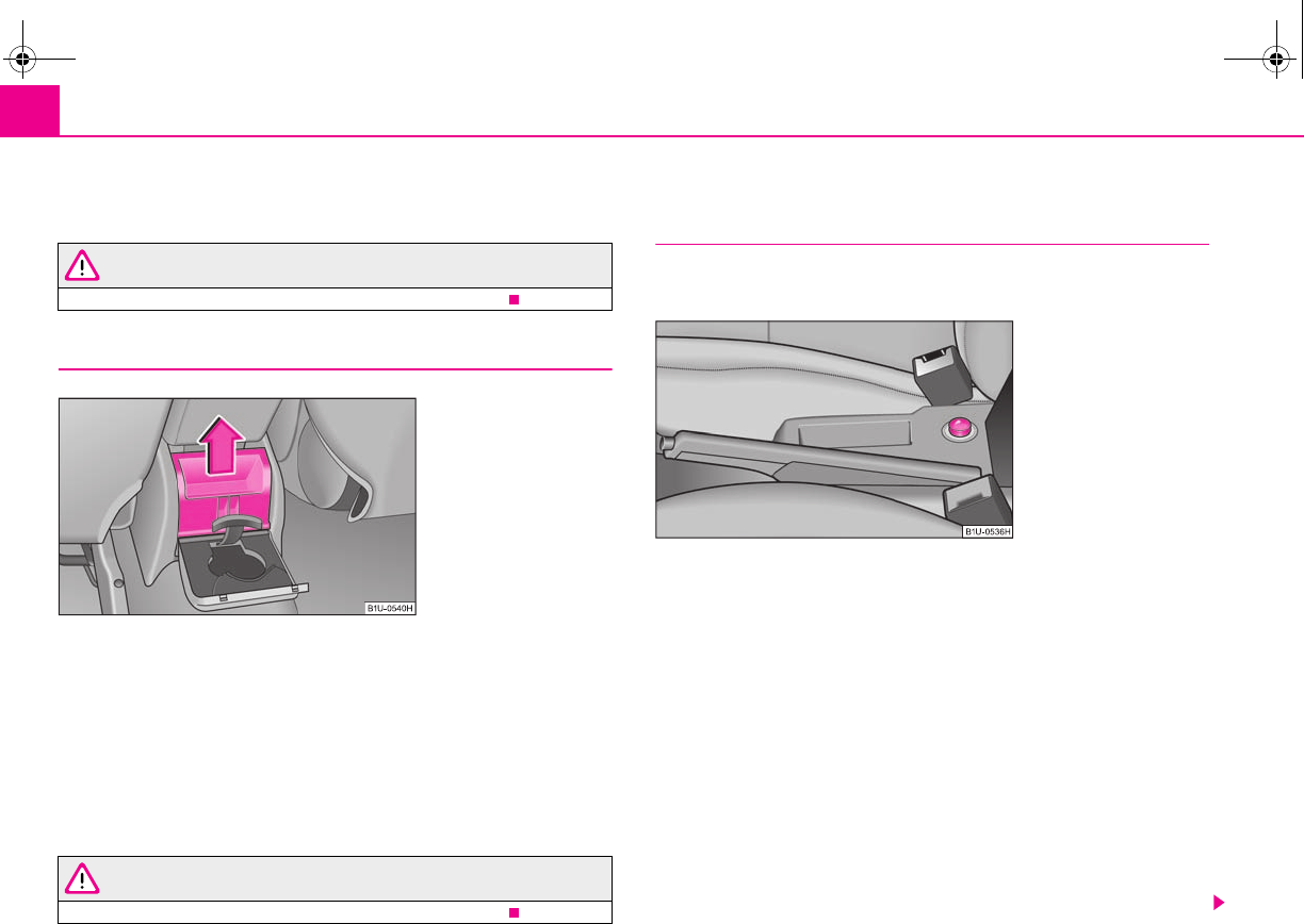
Seats and Storage78
Insert ashtray insert
– Insert the ashtray insert and press it slightly in direction of arrow .
WARNING
Never lay flammable objects in the ashtray basin - risk of fire!
Rear ashtray
Removing ashtray
– Fold the cover backwards and remove the ashtray in direction of
arrow.
Replacing ashtray
– Press the ashtray vertically downwards and fold the cover down.
There is a can holder attached to the inner side of the ashtray cover.
WARNING
Never lay flammable objects in the ashtray basin - risk of fire!
Cigarette lighter*, power sockets
Cigarette lighter
You can also use the socket on the cigarette lighter for other elec-
trical appliances.
Using the cigarette lighter
– Press in the button of the cigarette lighter ⇒fig. 91.
– Wait until the button jumps forward.
– Remove the cigarette lighter immediately and use it.
– Insert the cigarette lighter again into the socket.
Using the socket
– Take out the cigarette lighter.
– Insert the plug of the electrical appliance into the socket of the ciga-
rette lighter.
The 12 volt power socket can also be used to supply power to additional electrical
accessories with a power uptake up to 180 watts.
A
B
Fig. 90 Low centre console:
Rear ashtray
Fig. 91 Centre console: Ciga-
rette lighter
s2g8.b.book Page 78 Tuesday, April 7, 2009 8:53 AM
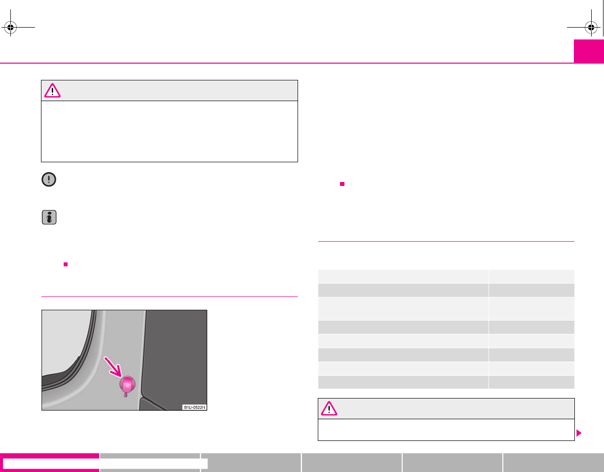
Seats and Storage 79
riving Tips General Maintenance Breakdown assistance Technical Data
WARNING
•Take care when using the cigarette lighter! Not paying proper attention
or incorrect use the cigarette lighter in an uncontrolled manner may result in
burns.
•The cigarette lighter and the power socket also operates when the igni-
tion is switched off or the ignition key withdrawn. You should therefore
never leave children unattended in the vehicle.
Caution
Always use matching plugs to avoid damaging the power socket.
Note
•Connecting electrical components when the engine is not running will
drain the battery of the vehicle - risk of battery draining!
•Further information ⇒page 179, “Accessories, changes and replacement of
parts”.
Power socket in the luggage compartment (Combi)
The socket is located on the left in the luggage compartment.
– Open the cover of the power socket ⇒fig. 92.
– Connect the plug of the electrical appliance to the socket.
The power socket, which fulfils the requirements of DIN standard ISO 4165, must
only be used for connecting approved electrical accessories with a power uptake of
up to 240 watts. The vehicle battery will be discharged in the process if the engine
is stationary.
The same remarks apply here as for ⇒page 78.
Further information ⇒page 179, “Accessories, changes and replacement of
parts”.
Storage compartments
Overview
You will find the following storage facilities in your vehicle:
WARNING
•Please do not place anything on top of the dash panel. Such objects
might slide or fall down when driving (when accelerating or cornering) and
Fig. 92 Luggage compart-
ment: Power socket
Storage compartment on the front passenger side ⇒page 80
Storage compartment below steering wheel ⇒page 9
Storage compartment in the middle part of the dash
panel
⇒page 9
Storage compartment for spectacles* ⇒page 80
Storage compartment in the front doors ⇒page 9
Front seat armrest with storage compartment* ⇒page 81
Rear armrest with storage compartment* ⇒page 81
Clothes hooks* ⇒page 82
s2g8.b.book Page 79 Tuesday, April 7, 2009 8:53 AM
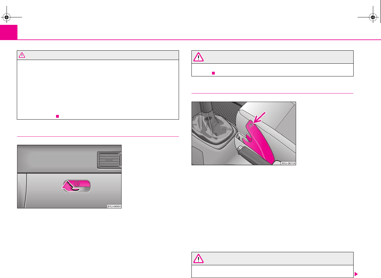
Seats and Storage80
may distract you from concentrating on the traffic situation - risk of acci-
dent!
•Use the storage compartments in the door panels only for small items
which do not project out of the compartment in order to avoid any interfer-
ence with the proper operation of the side airbags.
•Ensure that when driving no objects from the centre console of from
other storage possibilities may get into the footwell of the driver. You would
then no longer be able to apply the brakes, operate the clutch or accelerator
- risk of accident!
Storage compartment on the front passenger side
Opening and closing the storage compartment on the front
passenger side
– Pull the handle of the lid in direction of arrow ⇒fig. 93 and fold it
downwards.
– Raise the lid and press it until the catch is heard to engage.
The storage compartment can be locked and unlocked using the vehicle key (if the
storage compartment is lockable*).
WARNING
The storage compartment must always be closed when driving for safety
reasons.
Storage compartment for spectacles*
Opening and closing the storage compartment for spectacles
– Press on the cover of the storage compartment at the point of the
arrow, the compartment opens or closes ⇒fig. 94.
Removing
– Open the storage compartment in the vertical position and take it out
by pulling on the hinge.
Installing
– Installation takes place in the reverse order.
WARNING
The compartment must only be opened when removing or inserting objects
and otherwise must be kept closed.
WARNING (continued)
Fig. 93 Dash panel: Storage
compartment on the front
passenger side
Fig. 94 Centre console:
Storage compartment for
spectacles
s2g8.b.book Page 80 Tuesday, April 7, 2009 8:53 AM
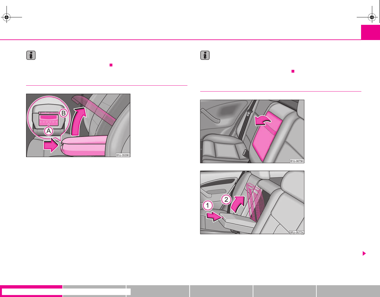
Seats and Storage 81
riving Tips General Maintenance Breakdown assistance Technical Data
Note
Do not insert particularly large spectacles.
Front seat armrest with storage compartment*
The armrest is adjustable in height.
Opening storage compartment
– Press button ⇒fig. 95.
– Open the lid of the armrest in the direction of arrow.
Closing storage compartment
– Fold down the cover of the armrest.
Setting height
– Press the button in direction of arrow.
– Fold the armrest downwards or upwards and release the button.
Note
The moving space of the arms can be restricted if the armrest is folded down. In city
traffic the armrest should not be folded down.
Rear seat armrest with storage compartment*
– The armrest can be folded forwards in direction of arrow with the aid
of the belt ⇒fig. 96.
Fig. 95 Armrest: Storage
compartment
A
B
A
A
Fig. 96 Rear seats: Armrest
Fig. 97 Rear seats: Fold the
armrest forwards
s2g8.b.book Page 81 Tuesday, April 7, 2009 8:53 AM
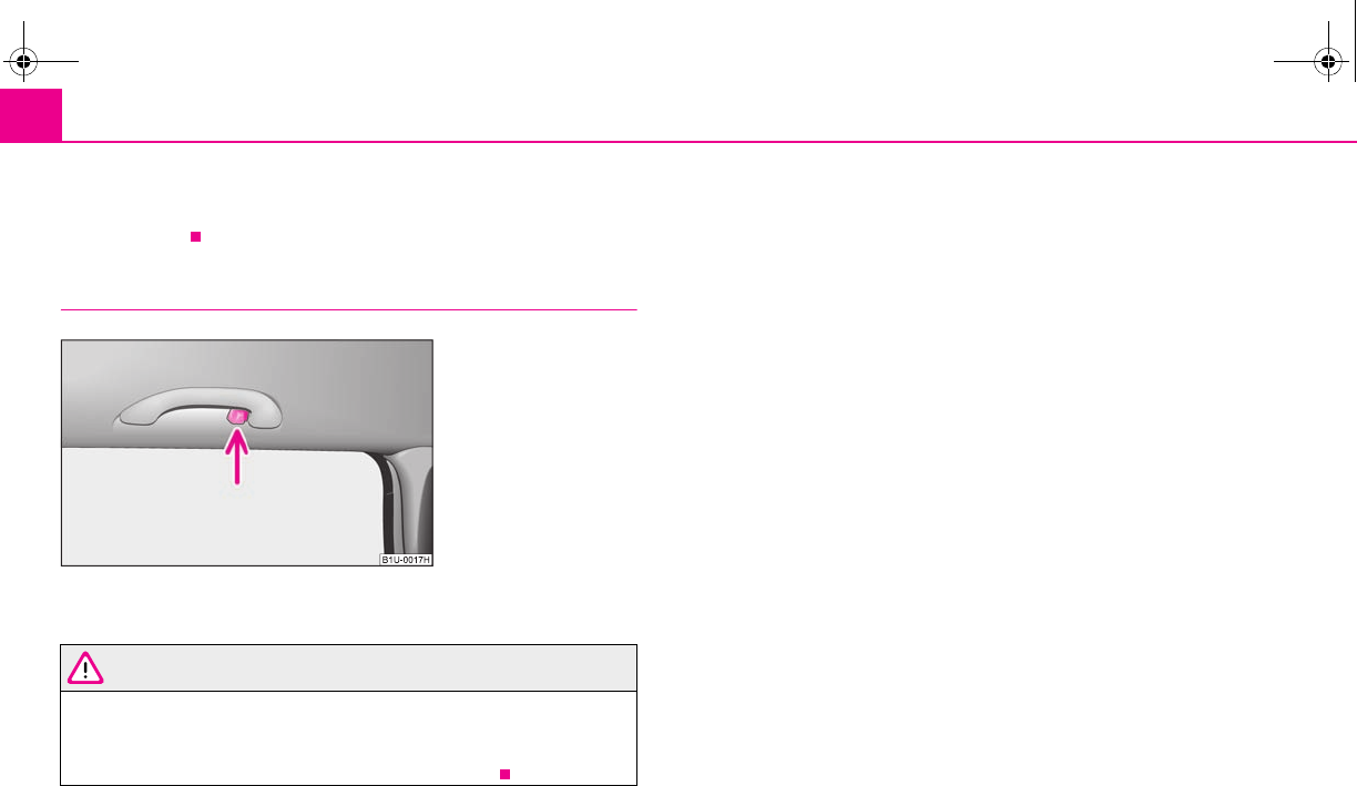
Seats and Storage82
– The armrest includes a storage compartment. Press the button in
direction of arrow and open the storage compartment in direction
of arrow .
Clothes hooks*
A clothes hook is located above the rear doors ⇒fig. 98.
WARNING
•Ensure that any clothes hanging from the hooks do not impair your
vision to the rear.
•Use the hooks for hanging only light items of clothing and ensure that
there are no heavy or sharp-edged objects in the pockets.
A
1
A
2
Fig. 98 Rear door: Clothes
hooks
s2g8.b.book Page 82 Tuesday, April 7, 2009 8:53 AM
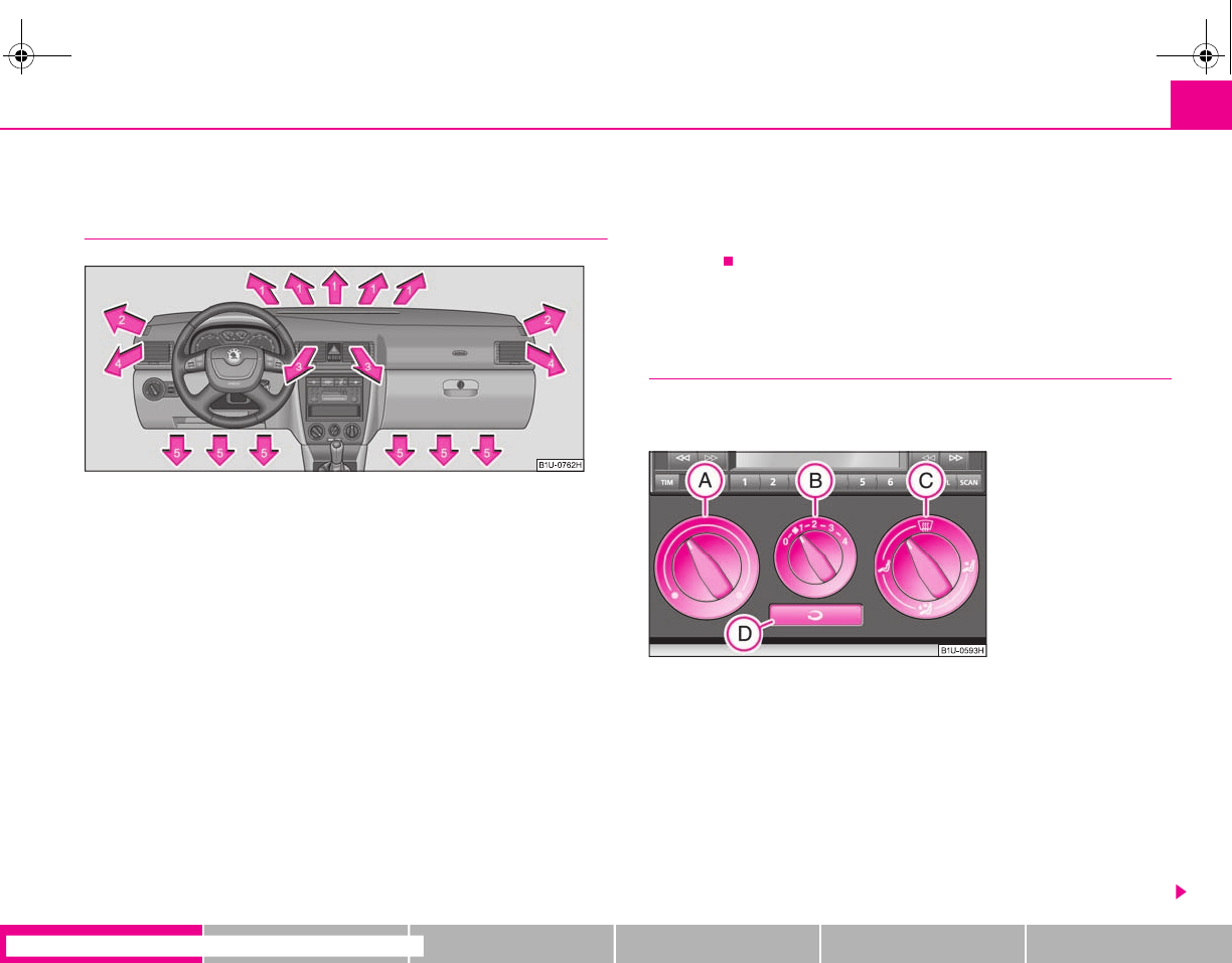
Heating and air conditioning system 83
riving Tips General Maintenance Breakdown assistance Technical Data
Heating and air conditioning system
Air outlet vents
Fig. 99 Air outlet vents
Open air outlet vents
– Turn the vertical thumbwheel (not when in the end position).
Close air outlet vents
– Turn the vertical wheel into the end position.
Redirecting air flow
– Swivel upward or downward the grille of the vents in order to change
the direction of the air flow using the vertically arranged thumbwheel.
– Turn the horizontal thumbwheel on the vent to the right or left in order
to change the air flow to the appropriate side.
You can set the air supply to the individual air outlet vents using the control
⇒fig. 100. Air outlet vents 3 and 4 ⇒fig. 99 can also be opened or closed individ-
ually.
Unwarmed or cooled air will flow out of the opened air outlet vents according to
the setting of the control dial ⇒fig. 100 and according to outer atmospheric
conditions.
Heating
Using the system
The heating system delivers air into the interior of the vehicle and
warms it as required.
Setting temperature
– Turn the control dial ⇒fig. 100 to the right in order to increase the
temperature.
– Turn the control dial to the left in order to increase the tempera-
ture.
Controlling blower
– Turn the blower switch into one of the positions, 1 to 4, in order to
switch the blower on.
A
C
A
A
Fig. 100 Heating: Control
elements
A
A
A
A
A
B
s2g8.b.book Page 83 Tuesday, April 7, 2009 8:53 AM
Heating and air conditioning system84
– Turn the blower switch into position 0 in order to switch the blower
off.
– If you wish to shut off the fresh air supply, use the button - recircu-
lated air mode ⇒.
Control for air distribution
– You can adjust the direction of the air flow using the air distribution
control ⇒page 83.
The air inlet in front of the windscreen must be free of ice, snow or leaves in order
to ensure that the heating and ventilation systems operate properly.
The heating effect is dependent upon the coolant temperature, thus full heat
output only occurs when the engine has reached its operating temperature.
The blower should aways be on to prevent the windows from misting up.
WARNING
You should not leave recirculated air mode on over a longer period of time,
as “stale” air may result in fatigue in the driver and occupants, divert your
attention and also cause the windows to mist up. The risk of having an acci-
dent increases. Switch recirculated air mode off as soon as the windows
begin misting up.
Note
•The whole heat output will be needed to unfrost the windscreen and side
windows. No warm air will be fed to the footwell. This can lead to restriction of the
heating comfort.
•The used air streams out through the air removal openings in the luggage
compartment.
•The button cannot be pressed if the control dial is in the position or
close to this position.
Set heating
Recommended settings of heating controls for:
A
B
A
D
A
C
A
D
A
C
s2g8.b.book Page 84 Tuesday, April 7, 2009 8:53 AM
Heating and air conditioning system 85
riving Tips General Maintenance Breakdown assistance Technical Data
Recirculated air mode
In recirculated air mode air is sucked out of the interior of the vehicle
and then fed back into the interior.
Recirculated air mode prevents polluted air outside the vehicle from
getting into the vehicle, for example when driving through a tunnel or
when standing in a traffic jam.
Switching recirculated air mode on
– Press the button - the warning light lights up in the button
⇒page 83, fig. 100.
Switching recirculated air mode off
– Press again the button - the warning light in the button goes out.
The button cannot be pressed if the control dial is in the position or close
to this position.
WARNING
You should not leave recirculated air mode on over a longer period of time,
as “stale” air may result in fatigue in the driver and occupants, divert your
attention and also cause the windows to mist up. The risk of having an acci-
dent increases. Switch recirculated air mode off as soon as the windows
begin misting up.
Air conditioning system*
Description
The air conditioning system is a combined cooling and heating
system. It makes it possible to optimally control the air temperature
at any season of the year.
Description of the air conditioning system
It is important for your safety and for your driving comfort that the air conditioning
system is operating properly.
Set-up Setting of the control dial Button Air outlet vents 3 Air outlet vents 4
Defrosting the windscreen and
side windows
To the right up to
the stop 3Switched off Closing Open and align with the side
window
Free windscreen and side win-
dows from mist In heating area 2 or 3 Switched off Closing Open and align with the side
window
The fastest heating To the right up to
the stop 3Switched off Opening Opening
Comfortable heating Desired tempera-
ture 2 or 3 or Switched off Closing Opening
Fresh air mode - ventilation To the left up to the
stop Desired position Switched off Opening Opening
A
A
A
B
A
C
A
D
A
C
s2g8.b.book Page 85 Tuesday, April 7, 2009 8:53 AM
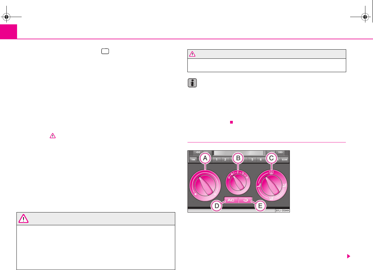
Heating and air conditioning system86
The air conditioning only operates if button ⇒fig. 101 is pressed and the
following conditions are met:
•engine running,
•outside temperature above +5 °C and
•blower switch switched on (positions 1 to 4).
If the cooling system is switched on, the temperature and air humidity drops in the
vehicle. The wellbeing of the occupants of the car is enhanced as a result of this
particularly at high outside temperatures and a high air humidity. The system
prevents the windows misting up during the cold season of the year.
The heating effect is dependent upon the coolant temperature, thus full heat
output only occurs when the engine has reached its operating temperature.
It is possible to briefly activate recirculated air mode in order to enhance the
cooling effect ⇒.
Air at a temperature of about 5°C may flow out of the vents under certain circum-
stances when the cooling system is operating. Lengthy and uneven distribution of
the air flow out of the vents (in particular at the leg area) and large differences in
temperature, for example when getting out of the vehicle, can result in chills in
sensitive persons.
The air inlet in front of the windscreen must be free of ice, snow or leaves in order
to ensure that the heating and cooling systems operate properly.
After switching on the cooling Condensation from the evaporator of the air condi-
tioning may drip down and form a puddle below the vehicle. This is quite normal
and not an indication of a leak!
WARNING
•For your own safety and that of other road users, ensure that all the
windows are free of ice, snow and misting. Please familiarize yourself about
how to correctly operate the heating and ventilation systems, how to demist
and defrost the windows, as well as with the cooling mode.
•You should not leave recirculated air mode on over a longer period of
time, as “stale” air may result in fatigue in the driver and occupants, divert
your attention and also cause the windows to mist up. The risk of having an
accident increases. Switch recirculated air mode off as soon as the windows
begin misting up.
Note
•We recommend that you do not smoke in the vehicle when the recirculating air
mode is operating since the smoke which is drawn at the evaporator from the inte-
rior of the vehicle forms deposits in the evaporator of the air conditioning system.
This produces a permanent odour when the air conditioning system is operating
which can only be eliminated through considerable effort and expense (replace-
ment of compressor).
Using the system
Setting temperature
– Turn the control dial ⇒fig. 101 to the right in order to increase the
temperature.
– Turn the control dial to the left in order to increase the tempera-
ture.
AC
A
DWARNING (continued)
Fig. 101 The air conditioning
system: Control elements
A
A
A
A
s2g8.b.book Page 86 Tuesday, April 7, 2009 8:53 AM
Heating and air conditioning system 87
riving Tips General Maintenance Breakdown assistance Technical Data
Controlling blower
– Turn the blower switch into one of the positions, 1 to 4, in order to
switch the blower on.
– Turn the blower switch into position 0 in order to switch the blower
off.
– IF you wish to close the inlet for fresh air, use the switch - Recir-
culated air mode ⇒page 88.
Control for air distribution
– You can adjust the direction of the air flow using the air distribution
control ⇒page 83.
switching cooling on and off
– Press the button ⇒page 86, fig. 101. The warning light lights
up in the button.
– When you again press the switch , the cooling system is switched
off. The warning light in the button goes out.
Note
•The whole heat output will be needed to unfrost the windscreen and side
windows. No warm air will be fed to the footwell. This can lead to restriction of the
heating comfort.
•The used air streams out through the air removal openings in the luggage
compartment.
•If the cooling system has not been switched on for a lengthy period, odours may
be produced at the evaporator because of deposits. Switch the cooling system on
at least once a month for approximately 5 minutes at the highest blower stage - also
during the cold season of the year - in order to remove such odours. Also open a
window for a short time.
•Please refer to the information regarding recirculated air mode ⇒page 88.
Setting air conditioning system
Recommended settings of the control elements of the air conditioning system for
the respective operating modes:
A
B
A
B
A
E
A
C
AC
A
D
AC
Set-up Setting of the control dial Button Air outlet vents 3 Air outlet vents 4
Defrosting the windscreen
and side windows
To the right up
to the stop 3Switched off Do not switch on Closing Open and align with the
side window
Free windscreen and side
windows from mist
Desired temper-
ature 2 or 3 switched on Do not switch on Closing Open and align with the
side window
The fastest heating To the right up
to the stop 3Switched off briefly switched on Opening Opening
Comfortable heating Desired temper-
ature 2 or 3 or Switched off Do not switch on Closing Opening
A
A
A
B
A
C
A
D
A
E
s2g8.b.book Page 87 Tuesday, April 7, 2009 8:53 AM
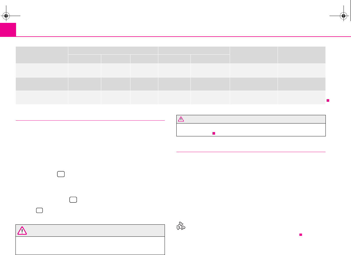
Heating and air conditioning system88
Recirculated air mode
In recirculated air mode air is sucked out of the interior of the vehicle
and then fed back into the interior.
Recirculated air mode prevents polluted air outside the vehicle from
getting into the vehicle, for example when driving through a tunnel or
when standing in a traffic jam.
Switching recirculated air mode on
– Press the button ⇒page 86, fig. 101 - the warning light lights up
in the button.
Switching recirculated air mode off
– Press again the button - the warning light in the button goes out.
The button cannot be pressed if the control dial is in the position or close
to this position.
WARNING
You should not leave recirculated air mode on over a longer period of time,
as “stale” air may result in fatigue in the driver and occupants, divert your
attention and also cause the windows to mist up. The risk of having an acci-
dent increases. Switch recirculated air mode off as soon as the windows
begin misting up.
Using the air conditioning system economically
The compressor on the air conditioning system uses power from the engine when
in cooling mode which will effect the fuel consumption.
It recommended to open the windows or the doors of a vehicle for which the inte-
rior has been strongly heated through the effect of direct sunlight in order to allow
the heated air to escape.
The cooling system should not be switched on while travelling when the window is
open.
The desired interior temperature can also be achieved without switching in the
cooling system just by switching to fresh air mode.
For the sake of the environment
When you economize on fuel, you also reduce pollutant emissions.
the fastest cooling To the left up to
the stop
briefly 4, then
2or 3 switched on briefly switched on Opening Opening
optimal cooling Desired temper-
ature 1, 2 or 3 switched on Do not switch on Opening Opening
Fresh air mode - ventilation To the left up to
the stop
Desired posi-
tion Switched off Do not switch on Opening Opening
Set-up Setting of the control dial Button Air outlet vents 3 Air outlet vents 4
A
A
A
B
A
C
A
D
A
E
A
C
WARNING (continued)
s2g8.b.book Page 88 Tuesday, April 7, 2009 8:53 AM
Heating and air conditioning system 89
riving Tips General Maintenance Breakdown assistance Technical Data
Climatronic* (automatic air conditioning)
Description
The Climatronic system is a combination of an automatic heating,
fresh air and cooling system which provides optimal comfort for the
occupants of the car.
The Climatronic maintains a constant temperature fully automatically, once it has
been set. This is achieved by automatically varying the temperature of the
outflowing air, the blower stages and the air distribution. The system also takes into
account bright sunlight which eliminates the need to alter the settings manually.
The automatic mode ⇒page 90 ensures maximum wellbeing of the occupants at
all times of the year.
Description of Climatronic system
The cooling operates only if the following conditions are met:
•engine running,
•outside temperature above +5 °C,
•the button is not pressed.
If the cooling system is switched on, the temperature and air humidity drops in the
vehicle. The wellbeing of the occupants of the car is enhanced as a result of this
particularly at high outside temperatures and a high air humidity. The system
prevents the windows misting up during the cold season of the year.
The heating effect is dependent upon the coolant temperature, thus full heat
output only occurs when the engine has reached its operating temperature.
It is possible to briefly activate recirculated air mode in order to enhance the
cooling effect ⇒.
The air inlet in front of the windscreen must be free of ice, snow or leaves in order
to ensure that the heating and cooling systems operate properly.
The AC compressor is switched off at a high coolant temperature in order to provide
cooling at a high load of the engine.
After switching on the cooling Condensation from the evaporator of the air condi-
tioning may drip down and form a puddle below the vehicle. This is quite normal
and not an indication of a leak!
If you make a change before switching off the ignition, which differs from the auto-
matic mode, the changed functions remain stored. Only the function “circulating
air” is erased 20 minutes after switching off the ignition.
Recommended setting for all periods of the year:
•Set the temperature to 22 °C (72 °F).
•Press the button ⇒page 90, fig. 102.
•Move the air outlet vents 3 and 4, so that the air flow is directed slightly upwards
⇒page 83, fig. 99.
Switching over between degrees Celsius and degrees Fahrenheit
Press and hold the buttons 17 and 9 ⇒page 90, fig. 102. The infor-
mation in the desired temperature measuring unit appears in the display.
WARNING
•For your own safety and that of other road users, ensure that all the
windows are free of ice, snow and misting. Please familiarize yourself about
how to correctly operate the heating and ventilation systems, how to demist
and defrost the windows, as well as with the cooling mode.
•You should not leave recirculated air mode on over a longer period of
time, as “stale” air may result in fatigue in the driver and occupants, divert
your attention and also cause the windows to mist up. The risk of having an
accident increases. Switch recirculated air mode off as soon as the windows
begin misting up.
Note
•If the cooling system has not been switched on for a lengthy period, odours may
be produced at the evaporator because of deposits. Switch the cooling system on
at least once a month for approximately 5 minutes at the highest blower stage - also
during the cold season of the year - in order to remove such odours. Also open a
window for a short time.
ECON
AUTO
ECON AUTO
s2g8.b.book Page 89 Tuesday, April 7, 2009 8:53 AM
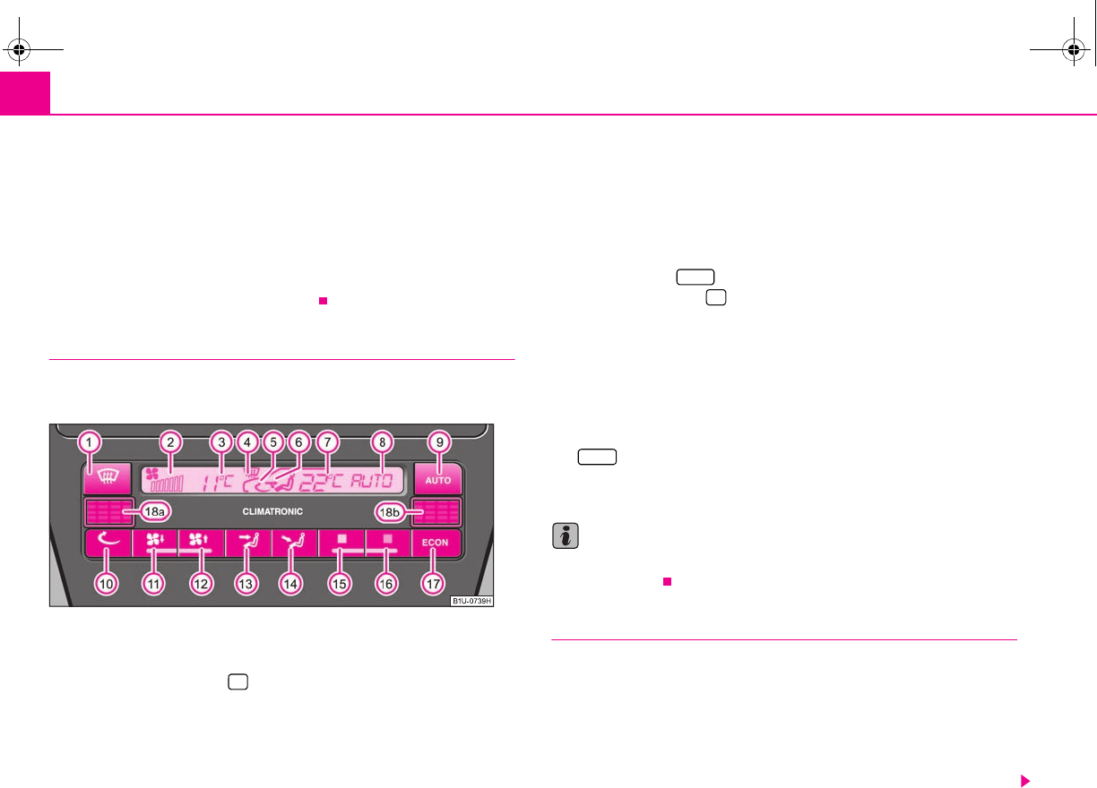
Heating and air conditioning system90
•We recommend that you do not smoke in the vehicle when the recirculating air
mode is operating since the smoke which is drawn at the evaporator from the inte-
rior of the vehicle forms deposits in the evaporator of the air conditioning system.
This produces a permanent odour when the air conditioning system is operating
which can only be eliminated through considerable effort and expense (replace-
ment of compressor).
•The used air streams out through the air removal openings in the luggage
compartment.
•Using the cooling economically ⇒page 88.
Overview of the control elements
The controls enable a separate setting of the temperature for the left
and right side.
Fig. 102 Climatronic: Control elements
The buttons
Defrosting the windscreen
Display
Display of blower stages
When switching off the automatic air conditioning with the button 11, the
outside temperature now indicates OFF, other information is not indicated.
Defrosting the windscreen
Recirculated air mode
Direction of air flow
Display of selected inside temperature, here: +22 °C
AUTO (automatic mode), ECON (AC compressor switched off) or OFF
(Climatronic switched off)
The buttons
Automatic mode
Recirculated air mode
Lower blower speed and button for switching off the air conditioning system
“OFF”
Higher blower speed and button for switching on the air conditioning system
Air flow to head
Air flow in the footwell
Decreasing the temperature
Increasing the temperature
(AC compressor switched off, i.e the cooling system)
Interior temperature sensor (on left-hand steering models) and (on
right-hand steering models).
Note
Do not glue or cover over the sensor, otherwise it could have an unfavourable effect
on the Climatronic.
Automatic mode
The automatic mode is used in order to maintain a constant temper-
ature and to demist the windows in the interior of the car.
Switching automatic mode on
– Set a temperature between +18°C (64 °F) and +29°C (84 °F).
– Move the air outlet vents 3 and 4 ⇒page 83, fig. 99, so that the air
flow is directed slightly upwards.
A
1
A
2
A
3
A
4
A
5
A
6
A
7
A
8
A
9AUTO
A
10
A
11
A
12
A
13
A
14
A
15
A
16
A
17 ECON
A
18
A
18a
A
18b
s2g8.b.book Page 90 Tuesday, April 7, 2009 8:53 AM
Heating and air conditioning system 91
riving Tips General Maintenance Breakdown assistance Technical Data
– Press the button - the warning light lights up in the button.
The automatic mode is switched off by pressing the button for the air distribution
or increasing or decreasing the blower speed. The temperature is nevertheless
regulated.
ECON mode
The cooling system is switched off in the ECON mode - heating and
ventilation are regulated automatically.
Switching ECON mode on
– Press the button - the warning light lights up in the button.
– Set a temperature between +18°C (64 °F) and +29°C (84 °F).
Recirculated air mode in ECON mode
– First of all press the button - the warning light lights up in the
button.
– Then press the button - the warning light lights up in the
button.
ECON mode operates only within the control temperature range from +18°C (64 °F)
up to +29°C (84 °F).
The ECON mode is switched off when pressing button or .
Please note that, in the ECON mode, the interior temperature cannot be lower than
the outside temperature. The interior is not cooled and the air is not dehumidified.
If you select the temperature below +18°C (64 °F), LO appears in the display. If you
select a temperature higher than + 29°C (84 °F), HI appears in the display. In the LO
position, the supplied air is neither warmed up nor cooled. In the HI position, the
system operates continuously with maximum heating capacity.
Please refer to the information regarding recirculated air mode ⇒page 91.
Defrosting windscreen
Defrosting windscreen - switching on
–Press the button ⇒page 90, fig. 102.
Defrosting windscreen - switching off
– Once again press the button or the button .
The temperature control is controlled automatically. More air flows out of the air
outlet vents 1 and 2.
Recirculated air mode
In recirculated air mode air is sucked out of the interior of the vehicle
and then fed back into the interior.
Recirculated air mode prevents polluted air outside the vehicle from
getting into the vehicle, for example when driving through a tunnel or
when standing in a traffic jam.
Switching recirculated air mode on
– Press the button - the warning light lights up in the button.
Switching recirculated air mode off
– Press again the button or the button - the warning light in
the button goes out.
WARNING
You should not leave recirculated air mode on over a longer period of time,
as “stale” air may result in fatigue in the driver and occupants, divert your
attention and also cause the windows to mist up. The risk of having an acci-
dent increases. Switch recirculated air mode off as soon as the windows
begin misting up.
AUTO
ECON
ECON
AUTO
AUTO
s2g8.b.book Page 91 Tuesday, April 7, 2009 8:53 AM
Heating and air conditioning system92
Note
If the windscreen mists up, press the button ⇒page 90, fig. 102. After the
windscreen has been demisted, press the button .
Setting temperature
You can set the interior temperature randomly with the buttons and
.
You can set the interior temperature between +18°C (64°F) and +29°C (84 °F). The
interior temperature is regulated automatically within this range. If you select the
temperature below +18°C (64 °F), “LO” appears in the display. If you select the
temperature higher than +29°C (84 °F), “HI” appears in the display. In both limit
positions the Climatronic operates at maximum cooling or heating capacity,
respectively. The temperature is not controlled in this case.
Lengthy and uneven distribution of the air flow out of the vents (in particular at the
leg area) and large differences in temperature, for example when getting out of the
vehicle, can result in chills in sensitive persons.
Controlling blower
There are a total of six blower stages available.
The Climatronic system controls the blower stages automatically in line
with the interior temperature. You can also, however, adapt the blower
stages manually to suit your particular needs.
– Press the button or ⇒page 90, fig. 102 in order to decrease or
increase the speed.
If you switch off the blowers, the Climatronic is switched off and OFF is shown in
the display.
The set blower speed is indicated by the lighting up of the respective number of
bars at the point .
WARNING
•“Stale air” may result in fatigue in the driver and occupants, reduce
attention levels and also cause the windows to mist up. The risk of having an
accident increases.
•Do not switch the Climatronic system off for longer than necessary.
•Switch the Climatronic system on as soon as the windows mist up.
Operational problems
If all the symbols on the display of the automatic air conditioning system flash for
approx. 15 seconds after switching on the ignition, then there is a fault in the system
- visit a specialist garage.
If the cooling system does not operate, the following faults may exist:
•the outside temperature is lower than +5°C,
•The compressor of the automatic air conditioning system was temporarily
switched off due to a too high temperature of the coolant,
•a blown fuse.
Check the fuse, replace it if necessary ⇒page 192. If a blown fuse is not the source
of the fault, switch the Climatronic off and have it checked.
If the cooling capacity decreases, switch the Climatronic off and have it checked.
A
1
AUTO
A
15
A
16
A
11
A
12
A
2
s2g8.b.book Page 92 Tuesday, April 7, 2009 8:53 AM
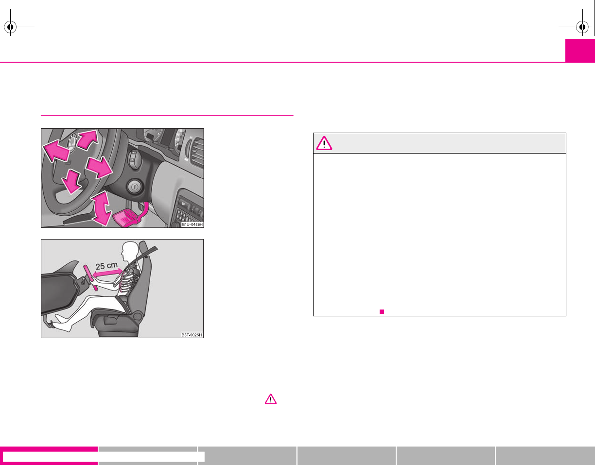
Starting-off and Driving 93
riving Tips General Maintenance Breakdown assistance Technical Data
Starting-off and Driving
Setting steering wheel position
You can set the height and the forward/back position of the steering
wheel to the desired position.
– Adjust the driver seat ⇒page 60.
– Pull the lever below the steering column ⇒fig. 103 down ⇒.
– Set the steering wheel to the desired position concerning height and
forward/back position.
– Then push the lever up against the steering column until it locks into
place.
WARNING
•You must not adjust the steering wheel when the vehicle is moving!
•The driver must maintain a distance of at least 25 cm to the steering
wheel ⇒fig. 104. Not maintaining this minimum distance will mean that the
airbag system will not be able to properly protect you - hazard!
•For safety reasons the lever must always be firmly pushed up to avoid the
steering wheel altering its position unintentionally when driving - risk of
accident!
•If you adjust the steering wheel further towards the head, you will reduce
the protection offered by the driver airbag in the event of an accident. Check
that the steering wheel is aligned to the chest.
•When driving, hold the steering wheel with both hands firmly on the
outer edge in the 9 o'clock and 3 o'clock position. Never hold the steering
wheel firmly in the 12 o'clock position or in another way (e.g. in the middle
of the steering wheel or at the inner steering wheel edge). In such cases,
injuries to the arms, the hands and the head can occur when the driver
airbag is deployed.
Fig. 103 Adjustable steering
wheel: Lever below steering
column
Fig. 104 Safe distance to
steering wheel
s2g8.b.book Page 93 Tuesday, April 7, 2009 8:53 AM
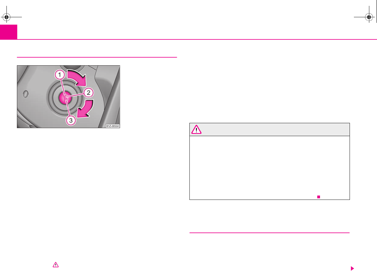
Starting-off and Driving94
Ignition lock
Petrol engines
- ignition switched off, engine off, the steering can be locked.
- ignition switched on
- start engine
Diesel engines
- interruption of fuel supply, ignition switched off, engine off, the steering can
be locked.
- heating glow plugs on, ignition switched on
•You should not switch on any major electrical components during the heating
period otherwise the vehicle battery will be drained unnecessarily.
- start engine
Applies to all models:
Position
To lock the steering, with the ignition key withdrawn, turn the steering wheel until
the steering locking pin is heard to engage. You should always lock the steering as
a general rule if you leave your vehicle. This acts as a deterrent against possible theft
of your vehicle ⇒.
Position
Move the steering wheel back and forward a little if the ignition key cannot, or
cannot easily be turned into this position, in order to release the steering lock.
Position
The engine is started in this position. At the same time switched on low beam or
main beam or other electrical components with major power consumption are
briefly switched off. The ignition key moves back into position when one
releases the key.
The ignition key must be turned back into position each time before starting the
engine again. The starter repeat lock in the ignition lock prevents the starter being
engaged when the engine is running and thus getting damaged.
WARNING
•When driving, the ignition key must always be in the position (igni-
tion switched on) without the engine running. This position is indicated by
the warning lights coming on. If this is not the case, it could result in unex-
pected locking of the steering wheel - risk of accident!
•Do not withdraw the ignition key from the lock until the vehicle has come
to a stop. The steering lock can engage immediately - risk of accident!
•Always withdraw the ignition key if you are going to leave the vehicle,
even for a short time. This is particularly important if children are left in the
vehicle. The children might otherwise start the engine or switch on electrical
equipment (e.g. power windows) - risk of accident or injury!
Starting the engine
General
You can only start the engine only using an original ignition key.
•Place the gearshift lever into neutral and put on the handbrake firmly before
starting the engine.
•The clutch pedal should be fully depressed when starting the engine - the
starter then only has to crank the engine.
Fig. 105 Ignition lock posi-
tions
A
1
A
2
A
3
A
1
A
2
A
3
A
1
A
2
A
3
A
2
A
1
A
2
s2g8.b.book Page 94 Tuesday, April 7, 2009 8:53 AM
Starting-off and Driving 95
riving Tips General Maintenance Breakdown assistance Technical Data
•Let go of the key as soon as the engine starts otherwise there may be damage
to the starter.
The engine running noises may louder at first be louder for a short time after
starting the cold engine until oil pressure can be built up in the hydraulic valve
clearance compensation. This is quite normal and is not an operating problem.
If the engine does not start ...
You can use the battery of another vehicle as a jump-start aid ⇒page 188.
It is only possible to tow-start vehicles fitted with a manual gearbox. The tow-
starting distance must not be more than 50 metres ⇒page 191.
WARNING
•Never run the engine in non ventilated or enclosed areas. The exhaust
gases of the engine contain besides the odorless and colourless carbon
monoxide a poisonous gas - hazard! Carbon monoxide can cause uncon-
sciousness and death.
•Never leave your vehicle unattended with the engine running.
Caution
•The starter may only be operated (ignition key position ), if the engine is not
running. If the starter is immediately operated after switching off the engine, the
starter or the engine can be damaged.
•Avoid high engine revolutions, full throttle and high engine loads as long as the
engine has not yet reached its normal operating temperature - risk of damaging the
engine!
•Vehicles which are fitted with an exhaust gas catalytic converter should not be
tow-started over a distance of more than 50 metres.
For the sake of the environment
Never warm up the engine when the vehicle is standing. Drive off right away.
Through this the engine reaches its operating temperature more rapidly and the
pollutant emissions are lower.
Petrol engines
These engines are fitted with a starter system which selects the correct fuel-air
mixture for every external air temperature.
•Do not depress accelerator before and when starting engine.
•Interrupt the attempt at starting after 10 seconds if the engine does not start
right awayand wait for about 30 seconds before repeating the attempt.
•It is possible that the fuse on the electrical fuel pump is defect if the engine still
does not start. Check the fuse and replace it if necessary ⇒page 192.
•Contact the nearest specialist garage to obtain professional assistance.
It may be necessary, if the engine is very hot, to slightly depress the accelerator
after the engine has started.
Diesel engines
Glow plug system
Diesel engines are equipped with a glow plug system, the preglow period being
controlled automatically in line with the coolant temperature and outside temper-
ature.
The preglow indicator light comes on after the ignition has been switched on.
You should not switch on any major electrical components during the heating
period otherwise the vehicle battery will be drained unnecessarily.
•You should start the engine immediately after the glow plug warning light
has gone out.
•The glow plug warning light will come on for about one second if the engine is
at a normal operating temperature or if the outside temperature is above +5°C. This
means that you can start the engine right away.
•Interrupt the attempt at starting after 10 seconds if the engine does not start
right awayand wait for about 30 seconds before repeating the attempt.
•It is possible that the fuse on the diesel preglow system is defect if the engine
still does not start. Check the fuse and replace it if necessary ⇒page 192.
•Contact the nearest specialist garage to obtain professional assistance.
A
3
s2g8.b.book Page 95 Tuesday, April 7, 2009 8:53 AM
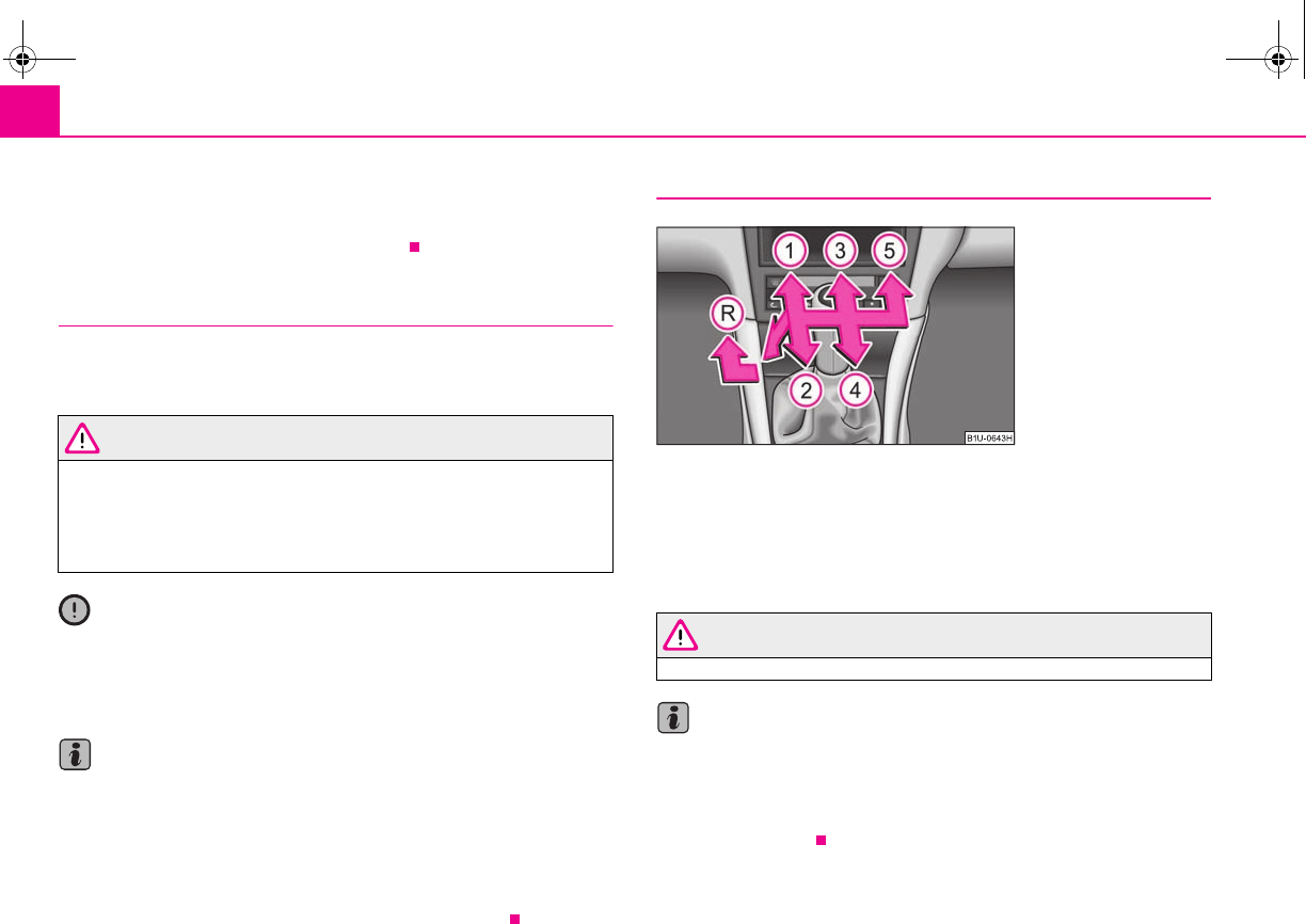
Starting-off and Driving96
Starting the engine after the fuel tank has run dry
It may take longer than normal to start the engine after refuelling if the fuel tank has
run completely dry - up to one minute. This is because the fuel system must first of
all be filled while the attempting to start the engine.
Switching off the engine
– The engine can be switched off by turning the ignition key from posi-
tion into ⇒page 94, fig. 105.
WARNING
•Never switch off the engine before the vehicle is stationary - risk of acci-
dent!
•The brake booster only operates when the engine is running. Greater
physical effort for braking is required when engine is switched off. Because
if you do not stop as normal, this can cause an accident and severe injuries.
Caution
you should not switch the engine off right away at the end of your journey after the
engine has been operated for a lengthy period at high loads but should be allowed
it to run at idling speed for about 2 minutes. This prevents any accumulation of heat
when the engine is switched off.
Note
•The radiator fan may continue running for a further 10 minutes or so after the
engine and the ignition have been switched off. The coolant fan may, however, also
switch on again after some time if the coolant temperature rises because of an
accumulation of heat in the engine or if the engine is warm and the engine
compartment is additionally heated by strong sunlight.
•This is why particular care is required when carrying out any work in the engine
compartment ⇒page 160, “Working in the engine compartment”.
Shifting
Shift into reverse only when the vehicle is stationary. Depress the clutch pedal and
hold it fully depressed. Wait a moment before engaging reverse gear in order to
avoid any shift noises.
The reversing lights will come on once reverse gear is engaged, provided the igni-
tion is on.
WARNING
Never engage the reverse gear when driving - risk of accident!
Note
•One should not lay the hand on the shift lever while driving the vehicle. The
pressure of the hand will be transferred to the gearshift forks in the gearbox. This
can, over a period of time, lead to early wear of the gearshift forks.
•Depress the clutch pedal fully when changing gears, in order to avoid unneces-
sary wear and damage.
A
1
Fig. 106 Shift pattern on
models fitted with 5-speed
manual gearbox
s2g8.b.book Page 96 Tuesday, April 7, 2009 8:53 AM
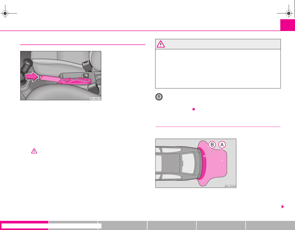
Starting-off and Driving 97
riving Tips General Maintenance Breakdown assistance Technical Data
Handbrake
Applying the handbrake
– Pull the handbrake lever up fully.
Releasing the handbrake
– Pull the handbrake lever up slightly and at the same time press in the
locking button ⇒fig. 107.
– Hold the button pressed and push the handbrake lever down fully
⇒.
The handbrake warning light lights up when the handbrake is applied, provided
the ignition is on.
A warning signal sounds and the following text appears in the display* if you have
inadvertently driven off with the handbrake applied:
HANDBRAKE ON
The handbrake warning is activated if you drive at a speed of more than 6 km/h for
more than 3 seconds.
WARNING
•Please note that the handbrake must be fully released. A handbrake
which is only partially released can result in the rear brakes overheating
which will have a negative effect on the operation of the brake system - risk
of accident! In addition this can result in premature wear of the rear brake
pads.
•Never leave children unattended in the vehicle. The children might, for
example, release the handbrake or take the vehicle out of gear. The vehicle
might then move off - risk of accident!
Caution
Each time the vehicle is parked, first of all apply the handbrake and then addition-
ally engage the 1st gear.
Rear parking aid*
The parking aid provides a warning of obstacles behind the vehicle.
The audible parking aid determines the distance between the rear bumper and an
obstacle located behind the vehicle with the aid of ultrasound sensors. The sensors
are integrated in the rear bumper.
Fig. 107 Centre console:
Handbrake
Fig. 108 Parking aid: Detec-
tion range of rear sensors
s2g8.b.book Page 97 Tuesday, April 7, 2009 8:53 AM
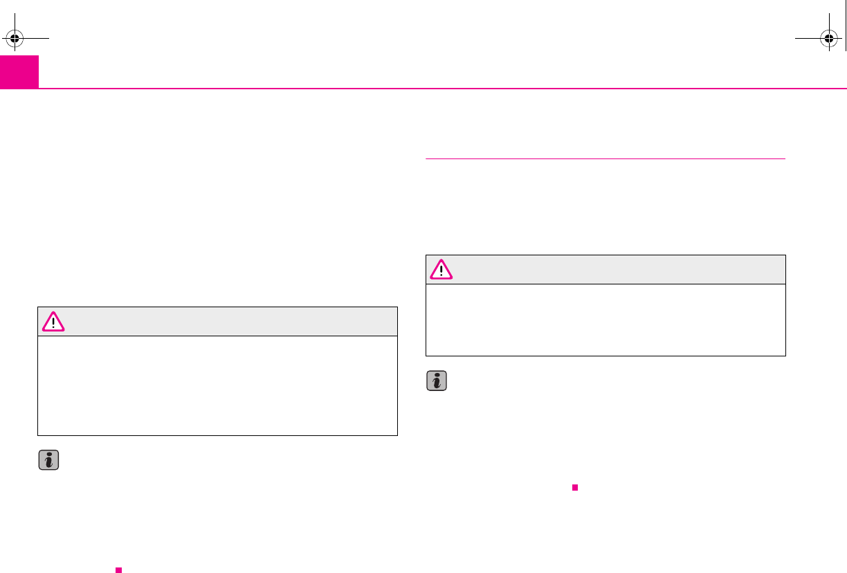
Starting-off and Driving98
Range of sensors
The clearance warning begins at a distance of about 160 cm from the obstacle (area
⇒page 97, fig. 108). The interval between the warning signals becomes shorter
as the clearance is reduced.
A continuous tone sounds from a distance of approx. 30 cm (area ) - danger
area. You should not reverse any further after this signal sounds!
Activating
The parking aid is activated automatically when reverse gear is engaged and the
ignition is turned on. This is confirmed by a brief acknowledgement signal.
Deactivating
The parking aid is deactivated by removing the reverse gear.
WARNING
•The parking aid is not a substitute for the driver paying proper attention
and it is always the driver's responsibility to take care when parking the
vehicle or carrying out similar manoeuvres.
•You should therefore satisfy yourself, before reversing, that there is no
small obstacle, such as a rock, thin post, trailer drawbar etc., behind your
vehicle. Such an obstacle might not be within the range detected by the
sensors.
Note
•The parking aid does not operate if you are towing a trailer (applies to models
which feature a factory-fitted towing device*).
•If a warning signal sounds for about 3 seconds after switching the ignition on
and engaging reverse gear, and there is no obstacle close to your vehicle, this indi-
cates a system fault. Have the fault rectified by a specialist workshop.
•The sensors must be kept clean and free of ice to enable the parking aid to
operate properly.
Cruise control system (CCS)*
Introduction
The cruise control system (CCS) maintains a constant speed, more than 30 km/h (20
mph), once it has been set, without you having to depress the accelerator pedal.
This is only possible within the range which is permitted by the power output and
braking power of the engine. The cruise control system makes it possible - particu-
larly on long journeys - for you to rest your “accelerator foot”.
WARNING
•The cruise control system must not, for safety reasons, be used in dense
traffic or on unfavourable road surfaces (such as icy roads, slippery roads or
loose chippings) - risk of accident!
•In order to prevent unintentional use of the cruise control system, always
switch off the system after use.
Note
•Models fitted with a manual gearbox: Always depress the clutch pedal if you
switch on the cruise control system when the gearbox is in Neutral. Otherwise the
engine can rev up unintentionally.
•The cruise control system is not able to maintain a constant speed when driving
on steep downhill sections. The weight of the vehicle increases the speed at which
it travels. One should shift down in good time to a lower gear or slow the vehicle
down by applying the foot brake.
A
A
A
B
s2g8.b.book Page 98 Tuesday, April 7, 2009 8:53 AM
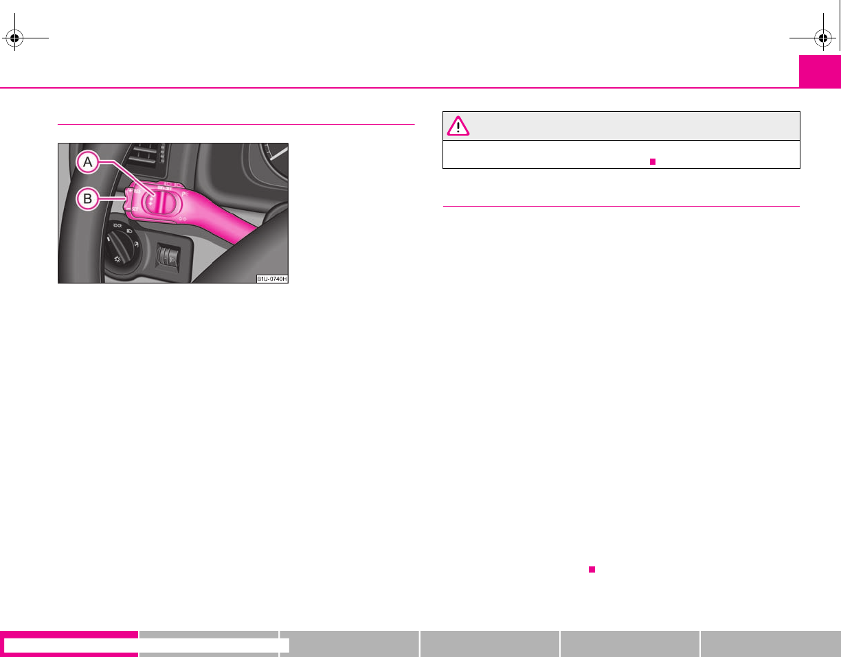
Starting-off and Driving 99
riving Tips General Maintenance Breakdown assistance Technical Data
Storing a speed
The cruise control system is operated by means of the slide switch and
rocker button in the left lever of the multi-functional switch.
– Switch on the cruise control system by sliding the switch ⇒fig. 109
into the ON position.
– After the desired speed has been reached, briefly press the rocker
button in the SET position.
After releasing the rocker button from the SET position, the speed you have
stored (above 30 km/hour 20 mph) is maintained at a constant speed without
having to depress the accelerator.
You can increase the speed by depressing the accelerator. Releasing the acceler-
ator will cause the speed to drop again to the set speed.
This does not apply, however, if you drive at a speed which is more than 10 km/h
higher than the set speed for a period of longer than 5 minutes. The stored speed
will be cancelled in the memory. You then have to re-store the desired speed.
One can reduce the speed in the usual manner. The system is switched off tempo-
rarily by actuating the brake or clutch pedal ⇒page 100.
WARNING
First ensure that it is not too high for the traffic conditions which exist at that
moment before resuming the stored speed.
Changing a stored speed
You can also change the speed of the vehicle without depressing the
accelerator.
Faster
–You can increase the stored speed without depressing the acceler-
ator, by pressing the rocker button ⇒fig. 109 in the RES position.
– The speed of the vehicle will increase continuously if you hold the
button pressed in the RES position. Once the vehicle has reached
the desired speed, release the rocker button. The set speed is then
stored in the memory.
Slower
–You can decrease the stored speed by pressing the rocker button
in the SET position.
– Holding down the rocker button pressed in the SET position will cause
the speed of the vehicle to reduce continuously. Once the vehicle has
reached the desired speed, release the rocker button. The set speed is
then stored in the memory.
– If you release the rocker button when the vehicle is travelling at a
speed of less than 30 km/h, the speed is not stored, the memory is
erased. It is then necessary to again store the speed with the rocker
button in the position SET after an increase in speed of the vehicle
to more than 30 km/hour.
Fig. 109 Operating lever:
Rocker button and switch of
cruise control system
A
A
A
B
A
A
A
B
A
B
A
B
A
B
A
B
A
B
s2g8.b.book Page 99 Tuesday, April 7, 2009 8:53 AM
Starting-off and Driving100
Switching off the cruise control system temporarily
– You can switch off temporarily the cruise control system, if you
depress the brake or clutch pedal.
– You can likewise switch off the cruise control system by sliding the
switch to the right - into the OFF position.
The set speed remains stored in the memory.
You can resume the stored speed by releasing the brake pedal or clutch pedal and
by briefly pressing the rocker button ⇒page 99, fig. 109 in the RES position.
WARNING
First ensure that it is not too high for the traffic conditions which exist at that
moment before resuming the stored speed.
Switching off the cruise control system completely
– Move the slide switch ⇒page 99, fig. 109 into the OFF position.
A
A
A
B
A
A
s2g8.b.book Page 100 Tuesday, April 7, 2009 8:53 AM
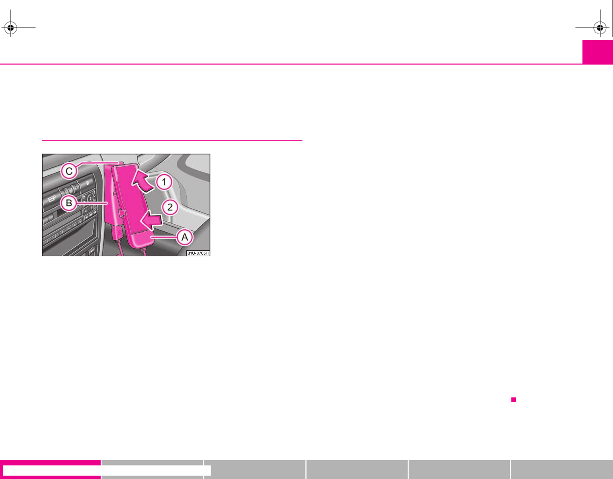
Communication 101
riving Tips General Maintenance Breakdown assistance Technical Data
Communication
Mobile phone, handsfree-system*
Universal preparation for the phone
Only one telephone mount is factory-fitted. An adapter for the phone can
be purchased from the Škoda original accessories. The mount is attached
to the centre console.
Insert mobile phone
– Insert the mobile phone into the adapter (as specified in manufac-
turer's instructions).
Inserting adapter with mobile phone into mount
– First insert the adapter with the mobile phone into the mount in
the direction of arrow until the adapter is touching the stop.
– Press the adapter slightly in the direction of arrow until it locks into
position.
Initialisation
– Withdraw the ignition key.
– Insert the adapter without the mobile phone into the mount .
– Plug the adapter cable into the mobile phone socket. The socket is
located on the mobile phone mount below.
– Switch on the ignition.
– Wait approximately 20 seconds, switch off the ignition and pull the
ignition key out of the ignition lock.
– Insert the mobile phone into the adapter (as specified in manufac-
turer's instructions) and switch on the ignition.
Removing the mobile phone with the adapter
– Press the button and remove the mobile telephone.
An initialisation must be carried out:
•after the first connection of the adapter;
•after reconnecting the battery;
•after pulling out the adapter cable from the power socket for the mobile phone.
This enables you to make full use of the advantages of a normal carphone (“hands-
free system” using a microphone integrated in the vehicle, optimal transmission of
signals using an external aerial etc.). The battery of the mobile phone is also
constantly charged.
Should you have any questions, please contact a specialist garage.
Please also refer to the additional instructions ⇒page 102.
Fig. 110 Universal prepara-
tion for the phone
A
A
A
B
A
1
A
2
A
B
A
A
A
C
s2g8.b.book Page 101 Tuesday, April 7, 2009 8:53 AM
Communication102
Mobile phones and two-way radio systems
The installation of a mobile phone and two-way radio system in a vehicle should be
carried out by a specialist garage.
Škoda Auto permits the operation of mobile phones and two-way radio systems
with a professionally installed external aerial and a maximum transmission power
of up to 10 watts.
It is essential that you inform a specialist garage about the possibilites to assemble
and operate mobile phones and two-way radio sets which have a power output of
more than 10 W. They will inform you which technical possibilities exist for retrofit-
ting mobile telephones and radio transmitters.
Operation of mobile phones or two-way radio systems may interfere with func-
tioning of the electronic systems of your vehicle. The reasons for this may be:
•no external aerial,
•external aerial incorrectly installed,
•transmission power greater than 10 watts.
You should therefore not operate a mobile phone or two-way radio system
inside the vehicle without the use of an external aerial, or with an external aerial
which has been incorrectly installed.
You should also be aware of the fact that only an external aerial makes it possible
to achieve the optimal range of such equipment.
WARNING
•If a mobile phone or two-way radio system is operated inside the vehicle
without using an external aerial, or with an external aerial which has been
incorrectly installed, the result can be excessive electromagnetic fields
which may cause harm to your health.
•Please concentrate fully at all times on your driving.
•You must not install two-way radio systems, mobile phones or mounts
on the covers of the airbags or within the immediate deployment range of
airbags. This might result in injuries to the occupants in the event of an acci-
dent.
Note
Please also refer to the operating instructions of the mobile phones and two-way
radio systems.
s2g8.b.book Page 102 Tuesday, April 7, 2009 8:53 AM
Passive Safety 103
riving Tips General Maintenance Breakdown assistance Technical Data
Safety
Passive Safety
Basic information
Driving the safe way
Passive safety measures reduce the risk of injury in accident situa-
tions.
In this section you will find important information, tips and notes on the subject of
passive safety in your vehicle. We have combined everything here which you
should be familiar with, for example, regarding seat belts, airbags, child seats and
safety of children. It is therefore important, in particular, to comply with the notes
and warnings in this section for your own interest and in the interest of those trav-
elling with you.
WARNING
•This chapter contains important information on how to use the vehicle
for the driver and his occupants. You will find further information on safety,
which concerns you and those travelling with you, in the following chapters
of this Owner's Manual.
•The complete on-board literature should always be in the vehicle. This
applies in particular, if you rent out or sell the vehicle.
Safety equipment
The safety equipment is part of the occupant protection and it can
reduce the risk of injuries in accident situations.
“Do not put at risk” your safety and the safety of those travelling with you . In the
event of an accident, the safety equipment can reduce the risk of injuries. The
following list contains part of the safety equipment in your vehicle:
•Three-point seat belts for all the seats*,
•belt force limiter for front seats*,
•belt tensioner for front seats*,
•seat belt height adjuster for front seats,
•front airbags*,
•side airbags*,
•anchoring points for child seat using the “ISOFIX” system,
•head restraint adjustable for height,
•adjustable steering column.
The specified safety equipment works together, in order to optimally protect you
and those travelling with you in accident situations. The safety equipment does not
protect you or the people travelling with you, if you or your occupants adopt an
incorrect seated position or the equipment is not correctly adjusted or used.
For this reason you will be provided with information on why this equipment is very
important, how it protects you and the occupants, what should be observed when
using the equipment and how you and the people travelling with you can make full
use of the existing safety equipment. This Owner's Manual contains important
warning notes, which you and those travelling with you should pay attention to in
order to reduce a risk of injury.
Safety concerns everybody!
Before setting off
The driver is always fully responsible for his occupants and for the
operating safety of the vehicle.
For your own safety and the safety of the people travelling with you, please pay
attention to the following points before setting off:
s2g8.b.book Page 103 Tuesday, April 7, 2009 8:53 AM
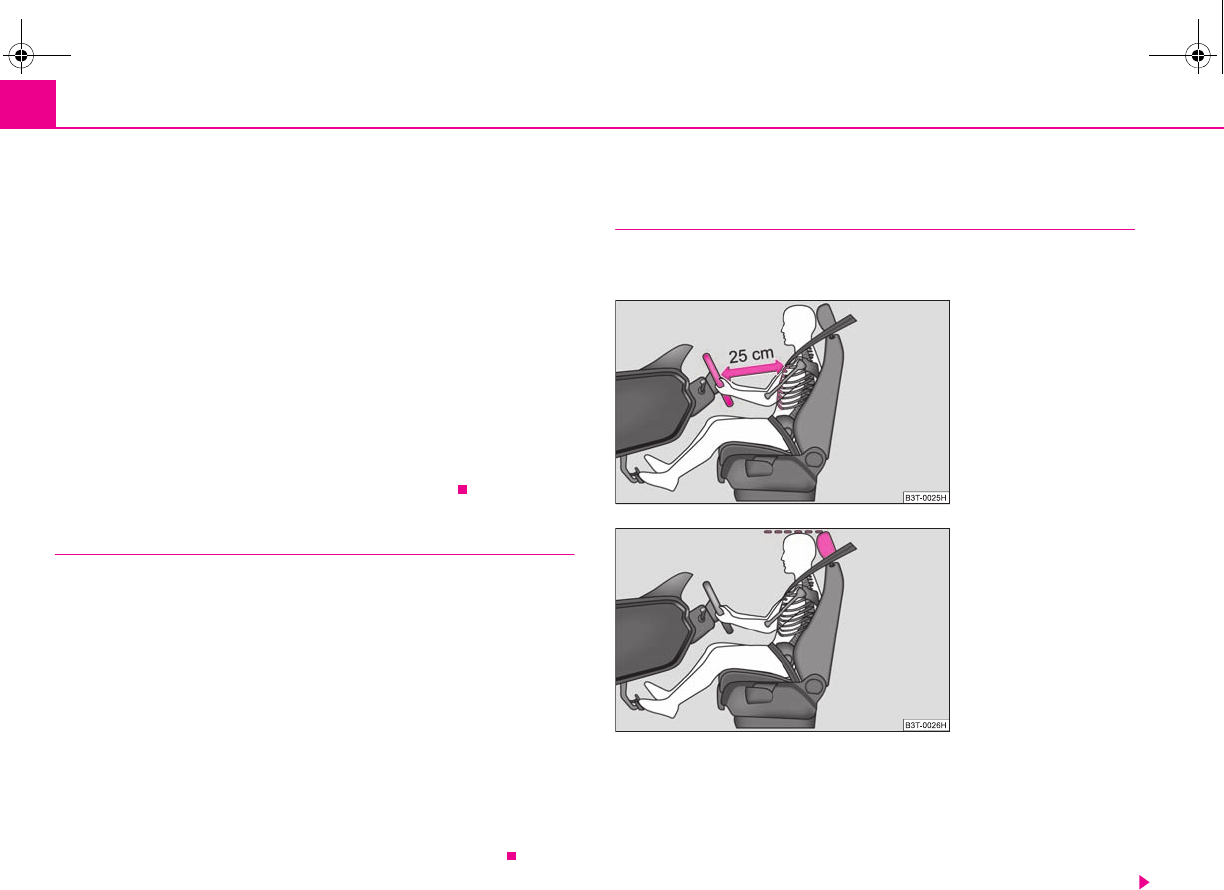
Passive Safety104
•Ensure that the lighting and the turn signal system are functioning properly.
•Inspect the tyre inflation pressure.
•Ensure that all the windows offer a good visibility to the outside.
•Safely attach the items of luggage ⇒page 68, “Loading the luggage compart-
ment”.
•Ensure that no objects can obstruct the pedal.
•Adjust the mirror, the front seat and the head restraint to match your body size.
•Point out to your occupants that the head restraints must be adjusted to match
their body size.
•Protect the children in suitable child seats with correctly fastened seat belts
⇒page 123, “Transporting children safely”.
•Adopt the correct seated position ⇒page 104, “Correct seated position”. Also
inform your occupants to adopt the correct seated position.
•Fasten the seat belt correctly. Also inform your occupants to properly fasten the
seat belts ⇒page 110, “How are seat belts correctly fastened?”.
What influences the driving safety?
The driving safety is primarily determined by the style of driving and
the personal behaviour of all the occupants.
The driver is fully responsible for himself and his occupants. If your driving safety is
effected, you place yourself and the oncoming traffic at risk. Please refer to the
following guidelines.
•Do not get distracted from concentrating on the traffic situation, e.g. by your
occupants or mobile phone calls.
•Never drive when your driving ability is impaired, e.g. through medication,
alcohol, drugs.
•Keep to the traffic regulations and the permissible speed limit.
•Adjust the driving speed at all times to the road condition as well as to the traffic
and weather conditions.
•Take regular breaks on long journeys - at the latest every two hours.
Correct seated position
Correct seated position for the driver
Correct seated position for the driver is important for safe and
relaxed driving.
For your own safety and to reduce the risk of injury in the event of an accident, we
recommend the following setting:
•Adjust the steering wheel so that the distance between the steering wheel and
your chest is at least 25 cm ⇒fig. 111.
•Position the driver seat in the forward/back direction so that you are able to fully
press the pedals with your legs at a slight angle.
Fig. 111 The correct distance
of the driver from the
steering wheel
Fig. 112 The correct head
restraint adjustment for the
driver
s2g8.b.book Page 104 Tuesday, April 7, 2009 8:53 AM
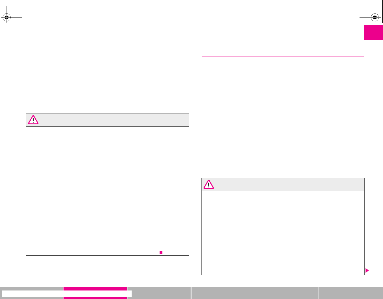
Passive Safety 105
riving Tips General Maintenance Breakdown assistance Technical Data
•Adjust the seat backrest so that you are able to reach the highest point of the
steering wheel with your arms at a slight angle.
•Adjust the head restraint so that the top edge of the head restraint is at the same
level as the upper part of your head ⇒page 104, fig. 112.
•Fasten the seat belt correctly ⇒page 110, “How are seat belts correctly
fastened?”.
Manual driver seat adjustment ⇒page 60, “Adjusting the front seats”.
Electrical driver seat adjustment ⇒page 61, “Adjusting front seats electrically*”.
WARNING
•The front seats and the head restraints must always be adjusted to match
the body size of the seat occupant as well as the seat belts must always be
correctly fastened in order to provide an optimal protection for you and your
occupants.
•The driver must maintain a distance of at least 25 cm to the steering
wheel ⇒page 104, fig. 111. Not maintaining this minimum distance will
mean that the airbag system will not be able to properly protect you -
hazard!
•When driving, hold the steering wheel with both hands firmly on the
outer edge in the 9 o'clock and 3 o'clock position. Never hold the steering
wheel firmly in the 12 o'clock position or in another way (e.g. in the middle
of the steering wheel or at the inner steering wheel edge). In such cases,
injuries to the arms, the hands and the head can occur when the driver
airbag is deployed.
•The seat backrests must not be angled too far back when driving other-
wise this will affect proper operation of the seat belts and of the airbag
system - risk of injury!
•Ensure that there are no objects in the footwell as any objects may get
behind the pedals during a driving or braking manoeuvre. You would then
no longer be able to operate the clutch, to brake or accelerate.
Correct seated position for the front passenger
The front passenger must maintain a distance of at least 25°cm from
the dash panel so that the combination of the airbag and the seat
belt offers the greatest possible safety when an airbag is deployed.
For the safety of the front passenger and to reduce the risk of injury in the event of
an accident, we recommend the following setting:
•Adjust the front passenger seat as far as possible to the rear.
•Adjust the head restraint so that the top edge of the head restraint is at the same
level as the upper part of your head ⇒page 104, fig. 112.
•Fasten the seat belt correctly ⇒page 110, “How are seat belts correctly
fastened?”.
In exceptional cases the front passenger airbag can be deactivated ⇒page 120,
“Deactivating an airbag”.
Manual front passenger adjustment ⇒page 60, “Adjusting the front seats”.
Electrical front passenger seat adjustment ⇒page 61, “Adjusting front seats electri-
cally*”.
WARNING
•The front seats and the head restraints must always be adjusted to match
the body size of the seat occupant as well as the seat belts must always be
correctly fastened in order to provide an optimal protection for you and your
occupants.
•The front passenger must maintain a distance of at least 25 cm to the
dash panel. Not maintaining this minimum distance will mean that the
airbag system will not be able to properly protect you - hazard!
•Always keep your feet in the footwell when the vehicle is being driven -
never place your feet on the instrument panel, out of the window or on the
surfaces of the seats. You will be exposed to increased risk of injury if it
becomes necessary to apply the brake or in the event of an accident. If an
airbag is deployed, you may suffer fatal injuries when adopting an incorrect
seated position!
s2g8.b.book Page 105 Tuesday, April 7, 2009 8:53 AM
Passive Safety106
•The seat backrests must not be angled too far back when driving other-
wise this will affect proper operation of the seat belts and of the airbag
system - risk of injury!
Correct seated position for the occupants on the rear seats
Occupants on the rear seats must sit upright, keep the feet in the
footwell and must have their seat belts correctly fastened.
To reduce the risk of injury in the event of a sudden braking manoeuvre or an acci-
dent, the occupants on the rear seats must observe the following:
•Adjust the head restraints so that the top edge of the head restraints are at the
same level as the upper part of your head ⇒page 104, fig. 112.
•Fasten the seat belt correctly ⇒page 110, “How are seat belts correctly
fastened?”.
•If you are transporting ⇒page 123, “Transporting children safely” children in
the vehicle, please use a suitable child restraint system.
WARNING
•The head restraints must always be adjusted to match the body size, in
order to offer an optimal protection for you and your occupants.
•Always keep your feet in the footwell when the car is being driven - never
put your feet out of the window or on the surfaces of the seats. You will be
exposed to increased risk of injury if it becomes necessary to apply the brake
or in the event of an accident. If an airbag is deployed, you may suffer fatal
injuries when adopting an incorrect seated position!
•If the occupants on the rear seats are not sitting upright, the risk of injury
is increased due to incorrect routing of the seat belt.
Examples of an incorrect seated position
An incorrect seated position can lead to severe injuries or death for
the occupants.
Seat belts offer their optimum protection only if the webbing of the seat belts is
properly routed. Incorrect seated positions considerably reduce the protective
functions of the seat belts and therefore increase the risk of injury due to an incor-
rect routing of the seat belt. The driver is fully responsible for himself and the occu-
pants, in particular for the children. Do not permit an occupant to adopt an incor-
rect seated position when the car is moving.
The following list contains the examples of seated positions which are dangerous
for the occupants. This list is not complete, however we would like you to get inter-
ested in this subject.
Therefore, while the car is moving never:
•stand up in the vehicle,
•stand up on the seats,
•kneel onto the seats,
•tilt the seat backrest fully to the back,
•lean against the dash panel,
•lie on the rear seats,
•only sit on the front area of the seat,
•sit to the side,
•lean out of the window,
•put the feet out of the window,
•put the feet on the dash panel,
•put the feet on the seat upholstery,
•occupy the footwell,
•have the seat belt not fastened,
•occupy the luggage compartment.
WARNING (continued)
s2g8.b.book Page 106 Tuesday, April 7, 2009 8:53 AM
Passive Safety 107
riving Tips General Maintenance Breakdown assistance Technical Data
WARNING
•If the occupant adopts an incorrect seated position, he is exposed to life-
threatening injuries, in case he is hit by a deployed airbag.
•Before setting off, please adopt the correct seated position and do not
change this seated position while the car is moving. Also advise your occu-
pants to adopt the correct seated position and not to change this seated
position while the car is moving.
s2g8.b.book Page 107 Tuesday, April 7, 2009 8:53 AM
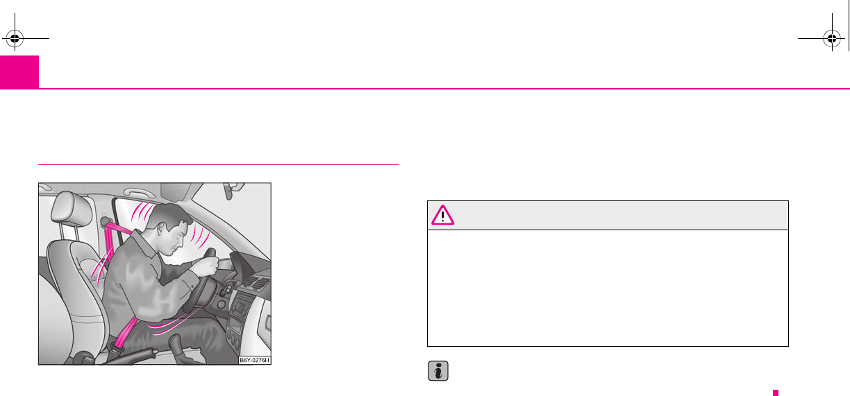
Seat belts108
Seat belts
Why seat belts?
It is a proven fact that seat belts offer good protection in accidents ⇒fig. 113. Thus
wearing a seat belt is a legal requirement in most countries.
Seat belts which have been correctly fastened and adjusted hold the occupants of
the car in the correct seated position ⇒fig. 113. The belts reduce the kinetic energy
(energy of motion) to a considerable extent. They also prevent uncontrolled move-
ments which, in turn, may well result in severe injuries.
The occupants of a vehicle who have fastened and correctly adjusted their seat belt,
profit to a major extent from the fact that the kinetic energy is optimally absorbed
by the belts. The structure of the front end of the vehicle and other passive safety
measures, such as the airbag system, also contribute to reducing the kinetic energy.
The energy produced is thus absorbed and there is less risk of injury.
Accident statistics prove that seat belts which are fastened and properly adjusted
reduce the risk of an injury and enhance the chance of survival in a major accident
⇒page 109.
It is important that you pay attention to safety measures, particularly when trans-
porting children in the vehicle ⇒page 123, “What you should know about trans-
porting children!”.
WARNING
•Fasten your seat belt each time before setting off, also when driving in
town! This also applies to the people seated at the rear - risk of injury!
•Expectant women must also always wear a seat belt. This is the only way
of ensuring optimal protection for the unborn child ⇒page 110, “Fastening
three-point seat belts”.
•It is important for the belt webbing to be properly routed if the seat belts
are to offer the maximum protection. You can see a description of how safety
belts should be fitted properly on the next pages.
Note
Please comply with any differing legal requirements when using the seat belts.
Fig. 113 Driver wearing seat
belt
s2g8.b.book Page 108 Tuesday, April 7, 2009 8:53 AM
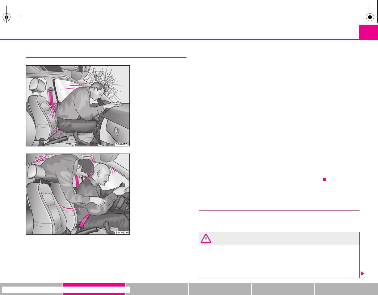
Seat belts 109
riving Tips General Maintenance Breakdown assistance Technical Data
The physical principle of a frontal collision
The physical principle of a frontal accident can be explained quite simply:
Motion energy, so-called kinetic energy, is produced as soon as the vehicle is
moving, both for the vehicle and its occupants. The magnitude of this kinetic energy
depends essentially on the speed at which the vehicle is travelling and on the
weight of the vehicle and the occupants. The greater the speed and weight increase,
the greater the amount of energy which has to be absorbed in the event of an acci-
dent.
The speed of the vehicle is, nevertheless, the most important factor. Doubling the
speed of the vehicle from 25 km/h up to 50 km/hour increases the kinetic energy
four times.
The common opinion that it is possible to support your body in a minor accident
with your hands, is incorrect. Even in a collision at only a low speed, the forces
acting on the body are such that it is no longer possible to support your body.
Even if you only drive at a speed within the range from 30 km/hour to 50 km/hour,
the forces which are produced on your body in the event of an accident can easily
exceed 10.000 N (Newton). This equals a weight of one tonne (1 000 kg).
In the event of a frontal collision, occupants of the car not wearing a seat belt, are
thrown forward and strike in an uncontrolled way parts of the interior of the car,
such as steering wheel, dash panel, windscreen,⇒fig. 114. The occupants of a
vehicle who have not fastened their seat belts may even be thrown out of the
vehicle. This can result in fatal injuries.
It is also important that rear seat occupants fasten their seat belts as they will other-
wise be thrown through the vehicle in an uncontrolled manner in the event of an
accident A rear seat passenger who has not fastened the seat belt is a danger not
only to himself but also for those seated at the front ⇒fig. 115.
Important safety information regarding the use of
seat belts
The correct use of the seat belts considerably reduces the risk of
injury!
WARNING
•The belt webbing must not be jammed in-between at any point or
twisted, or chafe against any sharp edges.
•It is important that the belt webbing is properly routed if the seat belts
are to offer their maximum protection ⇒page 110, “How are seat belts
correctly fastened?”.
Fig. 114 The driver is thrown
forward if not wearing a belt
Fig. 115 The rear seat occu-
pant is thrown forward if not
wearing a belt
s2g8.b.book Page 109 Tuesday, April 7, 2009 8:53 AM
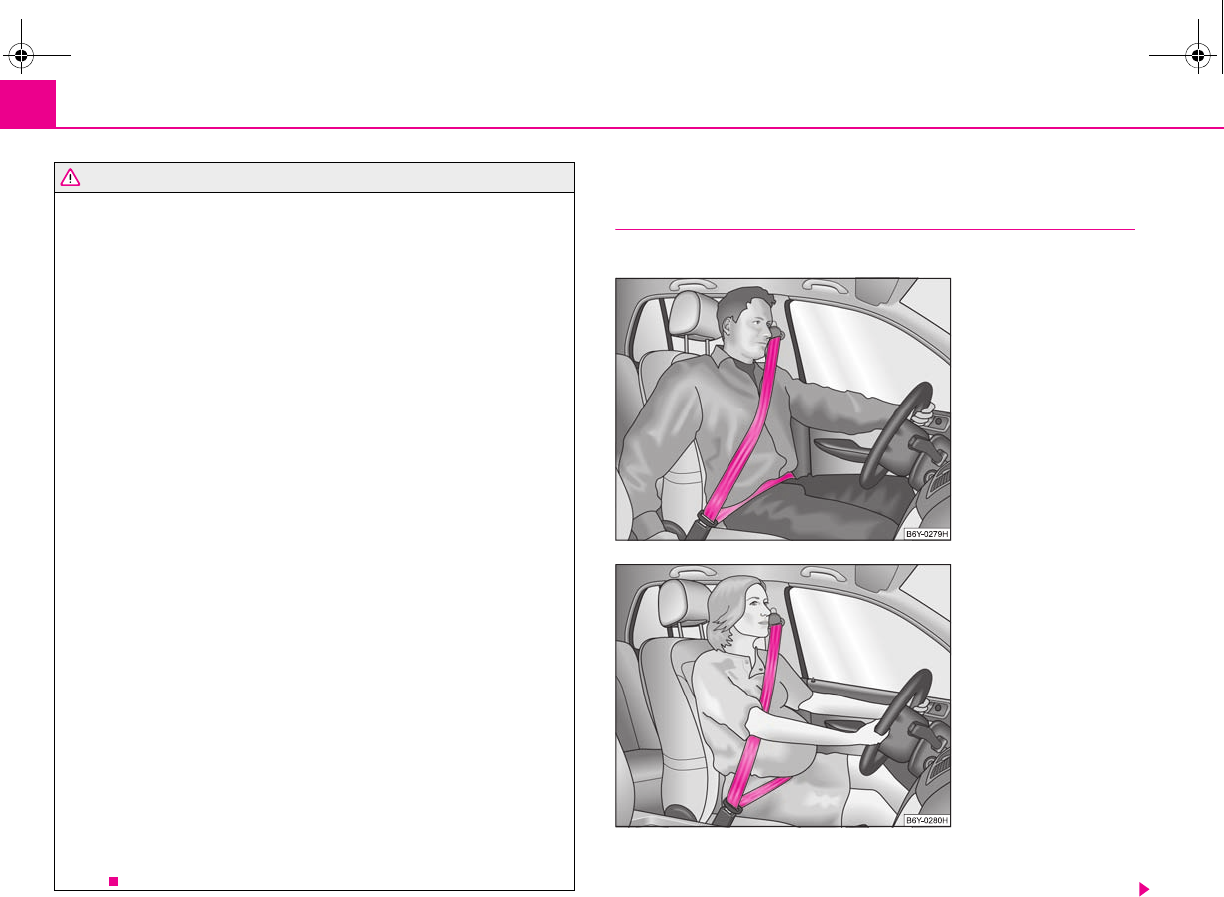
Seat belts110
•No two persons (also not children) should ever use a single seat belt
together.
•The maximum protection which seat belts can offer is only achieved if
you are correctly seated ⇒page 104, “Correct seated position”.
•The belt webbing must not run across solid or fragile objects (e.g. spec-
tacles, ball-point pens, keys etc.) as this may be a cause of injuries.
•Bulky, loose clothing (e.g. a winter coat over a jacket) does not allow you
to be correctly seated and impairs proper operation of the seat belts.
•It is prohibited to use clamps or other objects to adjust seat belts (e.g. for
shortening the belts for smaller persons).
•The lock tongue should only be inserted into the lock which is the correct
one for your seat. Wrong use of the safety belt will reduce its capacity to
protect and the risk of injury increases.
•The seat backrests of the front seats must not be tilted too far to the rear
otherwise the seatbelts can lose their effectiveness.
•The belt webbing must always be kept clean. Soiled belt webbing may
impair proper operation of the inertia reel ⇒page 153, “Seat belts”.
•The slot of the belt tongue must not be blocked by paper or similar
objects otherwise the belt tongue will not lock in place properly.
•Inspect the seat belts regularly to ensure they are in good condition. If
you find seat belts which have damage to the seat belt webbing, seat belt
connections, to the inertia reels or to the lock, the relevant safety belt must
be replaced by a specialist garage.
•The seat belts must not be removed or changed in any way. Do not make
an attempt to repair the seat belts yourself.
•Damaged seat belts which have been subjected to stress in an accident
and were therefore stretched, must be replaced - this is best done by a
specialist garage. The anchorage points of the belts must also be inspected.
The anchorage points for the belts should also be checked.
•In certain countries it is possible to use seat belts which differ in terms of
their operation from the seat belts which are described on the pages which
follow.
How are seat belts correctly fastened?
Fastening three-point seat belts
Fasten your seat belt before starting!
– Correctly adjust the front seat and the head restraint before fastening
your seat belt ⇒page 60.
WARNING (continued)
Fig. 116 Routing of webbing
over the shoulders and the
lap belt
Fig. 117 Routing of belt
webbing for an expectant
mother
s2g8.b.book Page 110 Tuesday, April 7, 2009 8:53 AM
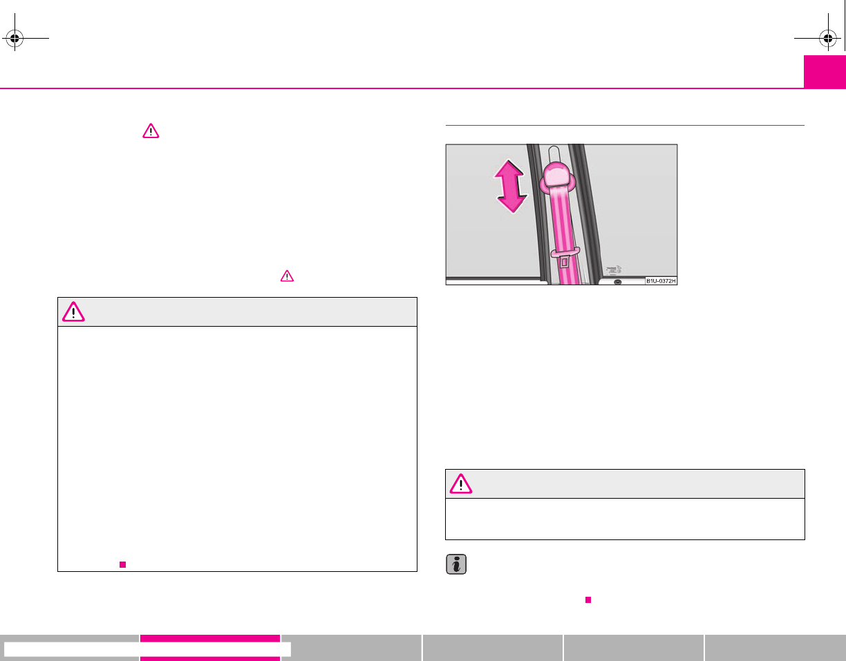
Seat belts 111
riving Tips General Maintenance Breakdown assistance Technical Data
– Slowly pull the belt webbing at the tongue of the lock over your chest
and pelvis ⇒.
– Insert the tongue of the lock into the seat belt buckle belonging to the
seat until it is heard to lock in place.
– Pull on the belt to check that it has also reliably engaged in the lock.
Each three-point seat belt is equipped with an inertia reel. This inertia reel offers
you complete freedom of movement if the belt is unreeled slowly. If the brakes are
applied suddenly, the inertia reel will block. It also blocks the belts when the car
accelerates, when driving uphill and when cornering.
Expectant mothers must also wear the seat belt ⇒.
WARNING
•The shoulder part of the seat belt must never run across your neck but
must run approximately over the middle of the shoulder and fit snugly
against the chest. The lap part of the belt must run across the hip and must
never be routed across the stomach. It must always fit snugly ⇒page 110,
fig. 116. Adjust the belt webbing as required.
•The lap part of the belt should be positioned as low as possible at the
pelvis of an expectant mother in order to avoid exerting any pressure on the
lower abdomen.
•Always ensure that the webbing of the seat belts is properly routed. Seat
belts which are not correctly adjusted can themselves cause injuries even in
minor accidents.
•A seat belt which is hanging too loose can result in injuries as your body
is moved forward by the kinetic energy produced in an accident and is then
suddenly held firm by the belt.
•Only insert the lock tongue into the lock which is the correct one for your
seat. This will affect the protection which the belt offers and increase the risk
of an injury.
Seat belt height adjuster
The seat belt height adjuster makes it possible for you to adapt the
routing of the three-point seat belt in the area of the shoulder to match
your body size.
– In order to adjust the height, press on the upper seat belt deflection
and push it into the desired direction up or down so that the shoulder
part of the belt is positioned approximately across the middle of your
shoulder ⇒page 110, fig. 116.
– Then pull firmly on the belt to ensure that the seat belt height adjuster
has correctly locked in place.
WARNING
Adjust the height of the belt in such a way that the shoulder part of the belt
is positioned approximately across the middle of your shoulder - on no
account across your neck.
Note
It is also possible to adapt the routing of the belt webbing at the front seats by
adjusting the height of the seat.
Fig. 118 Front seat: Seat belt
height adjuster
s2g8.b.book Page 111 Tuesday, April 7, 2009 8:53 AM
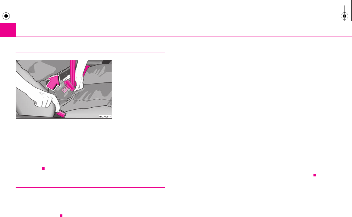
Seat belts112
Taking seat belts off
– Press the red button in the belt lock ⇒fig. 119. The spring force causes
the tongue of the lock to jump out.
– Guide the belt back with your hand to enable the inertia reel to wind
up the belt webbing more easily.
A plastic knob in the belt webbing holds the belt tongue in a position which is easy
to get hold of.
Three-point seat belt with the Interlock System*
A three-point safety belt with the Interlock System is used on some vehicles instead
of a pelvic belt.
If the backrest of the rear seats is not secured, the retractor blocks and the seat belt
cannot be reeled down.
Rear middle three-point safety belt with safety lock for a child
seat*
In order to attach a child seat the rear middle three-point safety belt with
the blocking, the so-called child safety locks, can be used.
Switching child safety lock on
– Attach the child safety seat with the three-point seat belt (self-
retracting) as stated in the manufacturer's instructions.
– Reel up the shoulder part of the belt completely. When the belt is
reeled up, this can be detected by a “clicking” noise.
– After fixing the child seat in place, let the belt freely reel up. Now the
belt can no longer be reeled down.
– Check if the safety lock is activated by pulling on the belt.
Switching child safety lock off
– By pressing the button in the lock of the safety belt, the blocking is
unblocked and afterwards the safety belt starts to reel up.
– After fully reeling up the belt, you can freely reel it down again.
Fig. 119 Releasing lock
tongue from belt lock
s2g8.b.book Page 112 Tuesday, April 7, 2009 8:53 AM
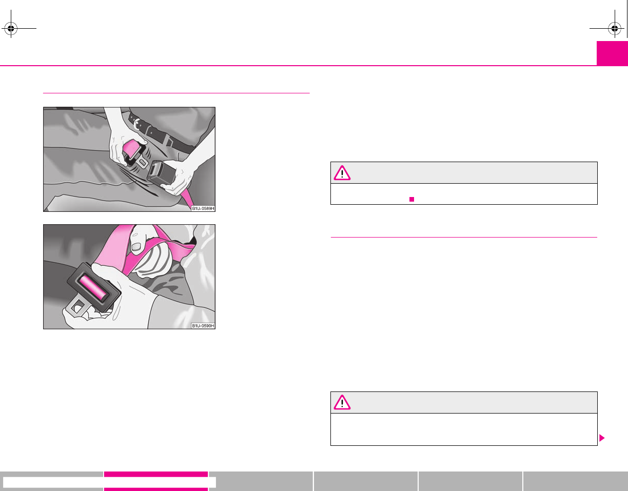
Seat belts 113
riving Tips General Maintenance Breakdown assistance Technical Data
The pelvic belt*
The rear middle seat is fitted with a pelvic belt. The lock part of the two-
point pelvic belt is operated in the same way as for a three-point safety
belt. An unused pelvic belt should be stowed away together with the lock
for safety reasons.
Extending the pelvic belt
– Hold the lock tongue at right angles to the belt webbing and pull
through the desired amount of belt webbing ⇒fig. 121.
Shortening the pelvic belt
– Pull on the free end of the belt.
– Fix the excess belt length by threading it through the plastic slider.
The adjustment of the belt length is facilitated by simultaniously pressing the belt
tongue and the belt cover lengthwise.
WARNING
The pelvic belt must always sit firmly across the pelvis; tighten the belt
webbing if necessary.
Belt tensioners
Safety for the driver and front passenger wearing their seat belts is enhanced by
the belt tensioners fitted to the inertia reels of the front three-point seat belts, in
addition to the protection afforded by the airbag system.
The three-point seat belts are automatically tensioned in the event of a frontal colli-
sion of a certain severity. The belt tensioners can also be deployed if the seat belts
are not fastened.
The belt tensioner is deployed in the event of a frontal collision of major severity. A
powder charge is ignited in the inertia reels during deployment. The belt webbing
is pulled into the inertia reels by a mechanical system and the belt is tensioned.
Belt tensioners are not activated in the event of minor frontal collisions, side and
rear-end collisions, in the case of a rollover and also not in accidents in which no
major forces are produced from the front.
WARNING
•Any work on the system including removal and installation of system
components because of other repair work, must only be carried out by a
specialist garage.
Fig. 120 Fasten pelvic belt
Fig. 121 Extending the pelvic
belt
s2g8.b.book Page 113 Tuesday, April 7, 2009 8:53 AM
Seat belts114
•The protective function of the system is only adequate for a single acci-
dent. If the belt tensioners have been deployed, it is then necessary to
replace the entire system.
•The Owner's Manual must also be handed over to the new owner if the
vehicle is sold.
Note
•Smoke is generated when the belt tensioners are deployed. This is not an indi-
cation of a fire in the vehicle.
•It is essential to pay attention to relevant safety regulations if the vehicle or indi-
vidual parts of the system are scrapped. Specialist garages are familiar with these
regulations and will be able to provide you with detailed information in this respect.
•When disposing of vehicle or parts of the system, it is important to comply with
the national legal requirements.
WARNING (continued)
s2g8.b.book Page 114 Tuesday, April 7, 2009 8:53 AM
Airbag system 115
riving Tips General Maintenance Breakdown assistance Technical Data
Airbag system
Description of the airbag system
General information on the airbag system
The front airbag system is complementary to the three-point seat belts and offers
additional protection for the head and chest area of the driver and passenger in the
event of a frontal collision.
In the case of a violent side crash, the side airbags* reduce the risk of injuries to the
occupants on the side of the collision ⇒.
The airbag system is only functional after the ignition has been switched on.
The operational readiness of the airbag system is monitored electronically. The
airbag warning light comes on for a few seconds each time the ignition is switched
on.
The airbag system (according to vehicle equipment) consists of:
•an electronic control unit,
•front airbag for the driver and the front seat passenger*,
•side airbags*,
•an airbag warning light in the instrument cluster,
•Switch for front passenger airbag* in front passenger storage compartment
⇒page 121,
•Indicator light for a switched off front seat passenger airbag* ⇒page 121.
A fault in the airbag system exists if:
•the airbag indicator light does not light up when the ignition is switched on,
•the warning light does not go out after about 4 seconds after the ignition is
switched on,
•the airbag indicator light goes out and comes on again after the ignition is
switched on,
•the airbag indicator light comes on or flickers when driving.
WARNING
•To enable the occupants of a vehicle to be protected with the greatest
possible effect when the airbag is deployed, the front seats must be
⇒page 104, “Correct seated position” correctly adjusted to match the body
size of the occupant.
•If you do not fasten the seat belts when driving, lean too far forward or
adopt an incorrect seated position, you are exposing yourself to increased
risk of injury in the event of an accident.
•Have the airbag system checked immediately by a specialist garage if a
fault exists. Otherwise, there is a risk of the airbag not being activated in the
event of an accident.
•No modifications of any kind may be made to parts of the airbag system.
•It is prohibited to manipulate individual parts of the airbag system as this
might result in the airbag being deployed.
•The protective function of the airbag system is sufficient for only one
accident. The airbag system must then be replaced if the airbag has been
deployed.
•The airbag system needs no maintenance during its working life.
•If you sell your car, please hand over the complete vehicle documenta-
tion to the new owener. Please note that the documents relating to the
possibility of deactivating the front passenger airbag are also part of the
vehicle documents!
•If the vehicle or individual parts of the airbag system are scrapped, it is
essential to observe the relevant safety precautions. Specialist garages are
familiar with these regulations.
•When disposing of vehicle or parts of the airbag system, it is important
to comply with the national legal requirements.
s2g8.b.book Page 115 Tuesday, April 7, 2009 8:53 AM
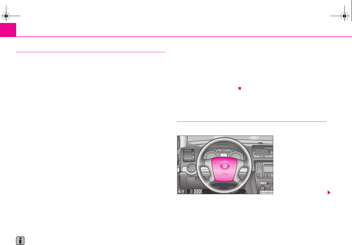
Airbag system116
When are the airbags deployed?
The airbag system is designed in such a way that the driver and the front passenger
airbag* are deployed in the event of a frontal collision of major severity.
In the case of a violent side crash, the side airbag* is deployed on the side of the
vehicle on which the collision occurs.
In certain accident situations, the front as well as the side airbags are deployed at
the same time.
The airbags are not deployed in the case of minor frontal and side collisions, in the
case of rear-end collisions and vehicle rollover.
Deployment factors
It is not possible to state globally which deployment conditions apply to the airbag
system in every situation as the circumstances which exist in the case of accidents
vary greatly. An important role in this case, for example, is played by factors such as
the type of object against which the vehicle impacts (hard, soft), the angle of impact,
the vehicle speed etc.
A decisive factor for the deployment of the airbags is the deceleration which occurs
during a collision. The control unit analyses the nature of the collision and activates
the relevant restraint system. If the vehicle deceleration which occurs and is meas-
ured during the collision remains below the prescribed reference values specified
in the control unit, the airbags are not deployed although the vehicle may well
suffer severe damage to the bodywork as a consequence of the accident.
The airbags are not deployed if:
•ignition is switched off;
•a minor frontal collision;
•a minor side collision;
•a rear-end collision;
•Rollover of the vehicle.
Note
•A grey white, non harmful gas is released when airbag is inflated. This is
perfectly normal and is not an indication of a fire in the vehicle.
•The dash panel must be replaced after the front passenger airbag has been
deployed.
•In the event of an accident in which the airbags are deployed:
−the interior lighting comes on (if the switch for the interior light is in the door
contact position),
−the hazard warning light is switched on;
−All the doors are unlocked.
Front airbags
Description of the front airbags
The airbag system is not a substitute for the seat belt!
Fig. 122 Driver airbag in the
steering wheel
s2g8.b.book Page 116 Tuesday, April 7, 2009 8:53 AM
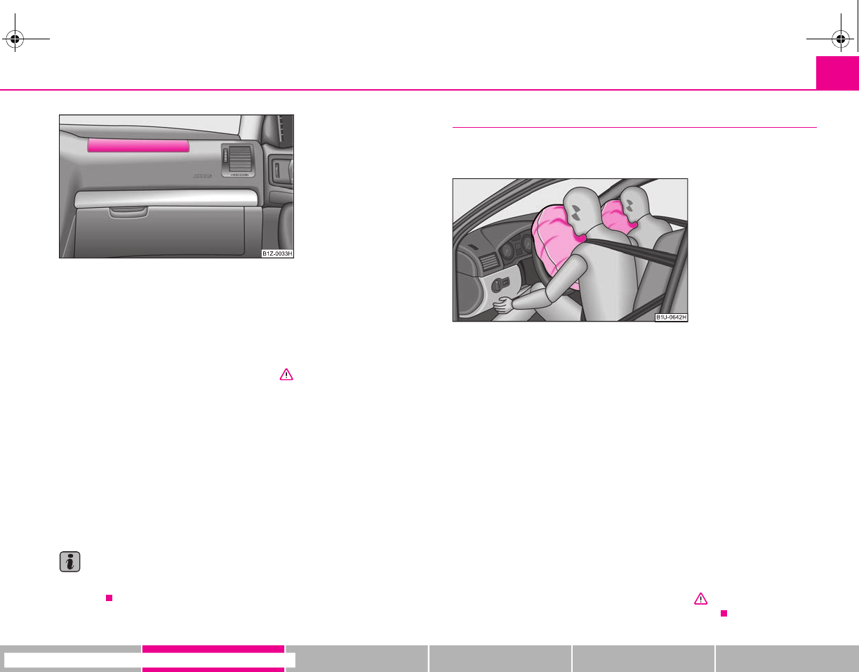
Airbag system 117
riving Tips General Maintenance Breakdown assistance Technical Data
The front airbag for the driver is housed in the steering wheel ⇒page 116, fig. 122.
The front airbag for the front passenger* is housed in the dash panel above the
storage compartment ⇒fig. 123. The installation positions are each marked with
the “AIRBAG” logo.
The front airbag system, in combination with three-point safety belts, offers addi-
tional protection for the head and chest area of the driver and front passenger in
the event of a frontal collision of major severity ⇒ in “Important safety informa-
tion regarding the front airbag system” on page 118.
The airbag is not a substitute for the seat belt, but is part of the complete passive
vehicle safety concept. Please note that an airbag can only offer you optimal
protection in combination with a seat belt which is fastened.
Apart from their normal protective function, a further task of the seat belts is to
also hold the driver and front passenger in a correct seated position in the event of
a frontal collision so as to enable the front airbags to offer the maximum protection.
You should therefore always fasten the seat belts, not only because this is required
by law, but also for safety reasons and for your own protection ⇒page 108, “Why
seat belts?”.
Note
The dash panel must be replaced after the front passenger airbag has been
deployed.
Function of the front airbags
Risk of injury to the head and chest area is reduced by fully inflated
airbags.
The airbag system is designed in such a way that the driver and the front passenger
airbag* are deployed in the event of a frontal collision of major severity.
In certain accident situations, the front and side airbags may be deployed together.
If the airbags are deployed, the airbags are filled with a propellant gas and inflated
in front of the driver and front passenger ⇒fig. 124. The airbags inflate in fractions
of a second and at a high speed in order to be able to offer that additional protec-
tion in the event of an accident. The forward movement of the driver and of the
front passenger is cushioned when they make contact with the fully inflated airbag
and the risk of injury to head and chest is thus reduced.
The specially developed airbag allows the gas to flow out of the inflated airbag in a
controlled manner (depending on the load of the particular car occupant) in order
to cushion head and chest areas. The airbag then deflates subsequently to such an
extent, after an accident, to again provide a clear view forward.
A grey white, non harmful gas is released when airbag is inflated. This is perfectly
normal and is not an indication of a fire in the vehicle.
The airbag develops enormous forces when triggered, which can lead to injuries if
the sitting position or seated position is not correct ⇒ in “Important safety
information regarding the front airbag system” on page 118.
Fig. 123 Front passenger
airbag in the dash panel
Fig. 124 Inflated airbags
s2g8.b.book Page 117 Tuesday, April 7, 2009 8:53 AM
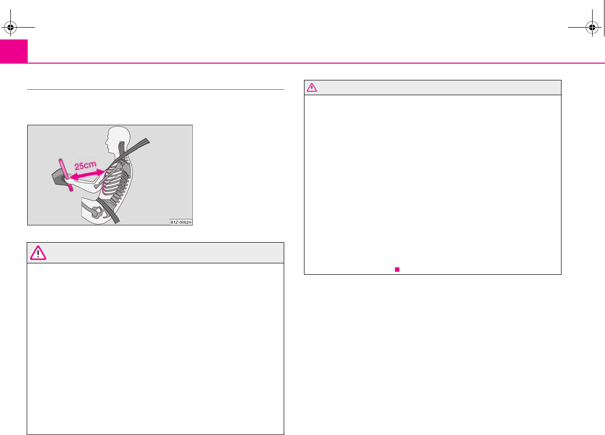
Airbag system118
Important safety information regarding the front airbag system
Correct use of the airbag system considerably reduces the risk of
injury!
WARNING
•Never transport children on the front seat of a vehicle without using a
proper restraint system. If airbags are deployed in the event of an accident,
the child might suffer severe or even fatal injuries!
•For the driver and front passenger it is important to maintain a distance
of at least 25 cm from the steering wheel or dash panel ⇒fig. 125. Not main-
taining this minimum distance will mean that the airbag system will not be
able to properly protect you - hazard! The front seats and the head restraints
must always also be correctly adjusted to match the body size of the occu-
pant.
•It is essential to always switch off the front passenger airbag and/or side
airbag when attaching a child safety seat on the front passenger seat where
the child is seated with its back facing in direction of travel (in some coun-
tries also when the child is facing the direction of travel) ⇒page 120, “Deac-
tivating an airbag”. If this is not done, there is a risk of the child suffering
severe or even fatal injuries if the front passenger airbag is deployed. In
certain countries national legal provisions also require that the side
passenger airbags be deactivated. When transporting a child on the front
passenger seat, please comply with the appropriate national regulations
regarding the use of child safety seats.
•There must not by any further persons, animals or objects positioned
between the front seated occupants and the deployment area of the airbag.
•The steering wheel and the surface of the airbag module in the dash
panel on the passenger side must not be stuck onto, covered or modified in
any other way. These parts should only be cleaned with a dry cloth or a cloth
moistened with water. No objects such as cup holders, mobile phone
mounts, etc. may be attached to the covers of the airbag modules or be
located within the immediate area.
•No modifications of any kind may be made to parts of the airbag system.
Any work on the airbag system including installing and removing system
components because of other repair work (e.g. removing the steering
wheel) must only be carried out by a specialist garage.
•Never carry out changes on the front bumper or on the body.
•Never place any objects on the surface of the front passenger airbag
module in the dash panel.
Fig. 125 Safe distance to
steering wheel
WARNING (continued)
s2g8.b.book Page 118 Tuesday, April 7, 2009 8:53 AM
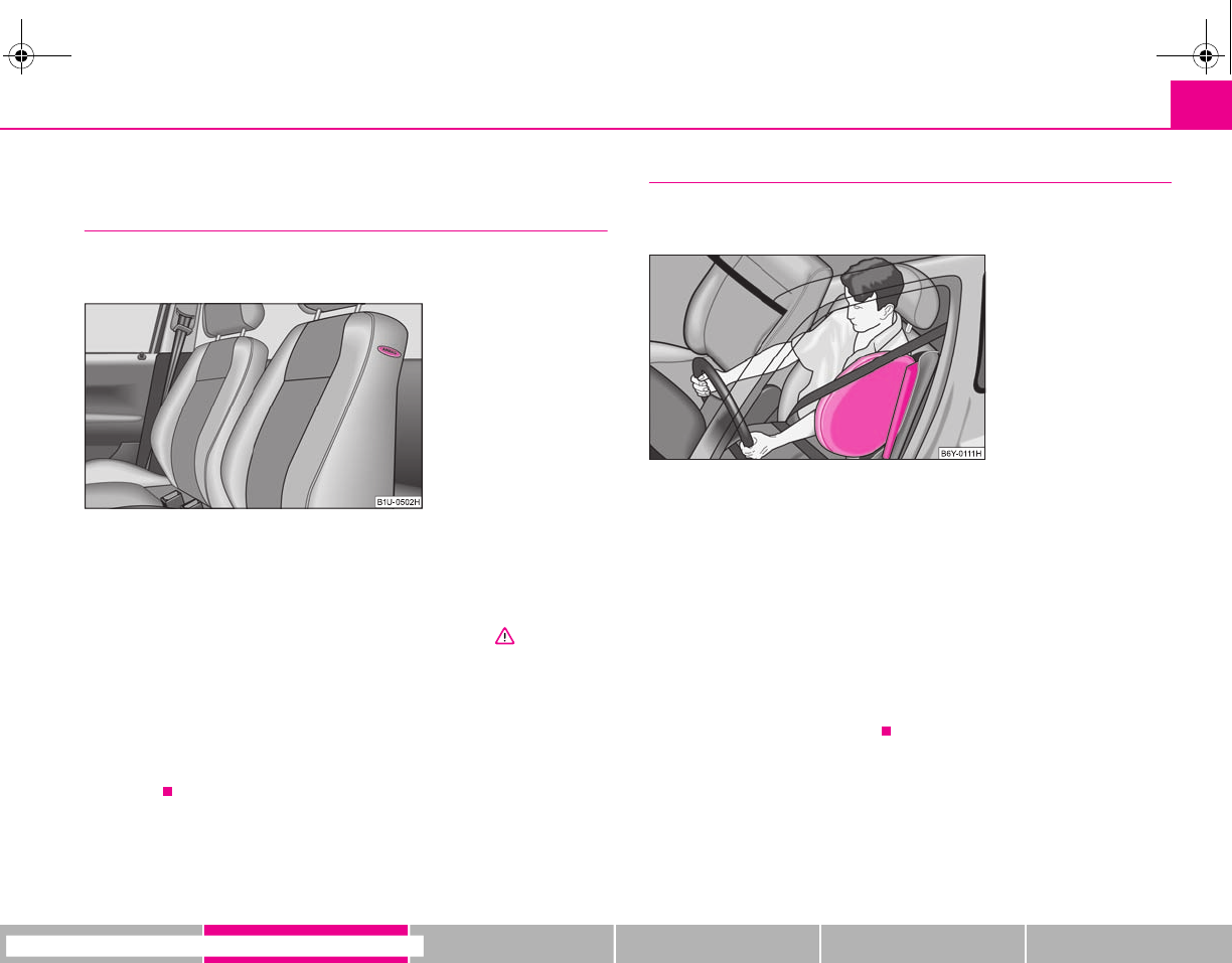
Airbag system 119
riving Tips General Maintenance Breakdown assistance Technical Data
Side airbags*
Description of side airbags
The side airbag increases protection of the passenger concerned in
the case of a side impact.
The side airbags are housed in the upholstery of the seat backrests of the front
seats.
The side airbag system in combination with the three-point seat belts, offers addi-
tional protection for the upper area of the body (chest, stomach and pelvis) of the
occupants of the vehicle in the event of severe side collisions ⇒ in “Important
safety information on the side airbag” on page 120.
Apart from their normal protective function, a further task of the seat belts is to
also hold the driver and front passenger in a correct seated position in the event of
a side collision so as to enable the side airbags to offer the maximum protection.
You should therefore always fasten the seat belts, not only because this is required
by law, but also for safety reasons and for your own protection ⇒page 108, “Why
seat belts?”.
Function of the side airbags
Risk of injury to the upper part of the body is reduced by fully inflated
side airbags.
In the case of a violent side crash, the side airbag in the front seat is deployed on
the side of the vehicle on which the collision occurs ⇒fig. 127.
In certain accident situations, the front and side airbags may be deployed together.
If an airbag is deployed, the airbag is filled with gas. The airbags inflate in fractions
of a second and at a high speed in order to be able to offer that additional protec-
tion in the event of an accident.
A grey white, non harmful gas is released when airbag is inflated. This is perfectly
normal and is not an indication of a fire in the vehicle.
The load of the occupants is cushioned when plunging into the fully inflated airbag
and the risk of injury to the entire upper body (chest, stomach and pelvis) is
reduced on the side facing the door.
Fig. 126 Installation position
of side airbag in driver seat
Fig. 127 Inflated side airbag
s2g8.b.book Page 119 Tuesday, April 7, 2009 8:53 AM
Airbag system120
Important safety information on the side airbag
Correct use of the airbag system considerably reduces the risk of
injury!
WARNING
•It is essential to always switch off the front passenger airbag and/or side
airbag when attaching a child safety seat on the front passenger seat where
the child is seated with its back facing in direction of travel (in some coun-
tries also when the child is facing the direction of travel) ⇒page 120, “Deac-
tivating an airbag”. If this is not done, there is a risk of the child suffering
severe or even fatal injuries if the front passenger airbag is deployed. In
certain countries national legal provisions also require that the side
passenger airbags be deactivated. When transporting a child on the front
passenger seat, please comply with the appropriate national regulations
regarding the use of child safety seats.
•Your head should never be positioned in the deployment area of the side
airbag. You might suffer severe injuries in the event of an accident. This
applies in particular to children who are transported without using a suit-
able child safety seat ⇒page 125, “Child safety and side airbag*”.
•If children adopt an incorrect seated position when travelling, they may
be exposed to an increased risk of injury in the event of an accident. This can
result in serious injuries ⇒page 123, “What you should know about trans-
porting children!”.
•There must not be any further persons, animals as well as objects posi-
tioned between the occupants and the deployment area of the airbag. No
accessories, such as a can holder, should be attached to the doors.
•Only hang light items of clothing on the clothes hooks to the vehicle.
Never leave any heavy or sharp-edged objects in the pockets of the items of
clothing.
•Ensure that there are no excessive forces, such as violent knocks, kicks
etc., impact on the backrests of the seats otherwise the system may be
damaged. The side airbags would not be deployed in such a case!
•Any seat or protective covers which you fit to the driver or front
passenger seats must only be of the type expressly authorised by Škoda
Auto. In view of the fact that the airbag inflates out of the backrest of the
seat, use of non-approved seat or protective covers would considerably
impair the protective function of the side airbag.
•Any damage to the original seat covers in the area of the side airbag
module must be repaired without delay by your specialist garage.
•The airbag modules in the front seats must not display any damage,
cracks or deep scratches. It is not permissible to use force in order to open
the modules.
•Any work on the side airbag system including removing and installing
system components because of other repair work (e.g. removing seats) must
only be carried out by a specialist garage.
Deactivating an airbag
Deactivating airbags
If any airbags have been deactivated, switch them on again as soon
as possible so that they are able to again provide their proper protec-
tion.
There is the technical means installed within your vehicle to switch off the front or
side* airbag using a diagnostic equipment (take out of commission).
This is why you should have the deactivation of the airbags carried out by a
specialist garage.
On vehicles equipped with the switch for deactivation of the airbags, you can deac-
tivate the front passenger airbag and/or side airbag by means of this switch
⇒page 121.
Deactivation of airbags is envisaged only for particular instances, such as if:
•You must in exceptional cases use a child seat on the front passenger seat
where the child is seated with its back to the direction of travel (in some countries
this must be in the direction of travel due to other legal regulations applying)
⇒page 123, “Important safety information regarding the use of child safety seats”;
WARNING (continued)
s2g8.b.book Page 120 Tuesday, April 7, 2009 8:53 AM
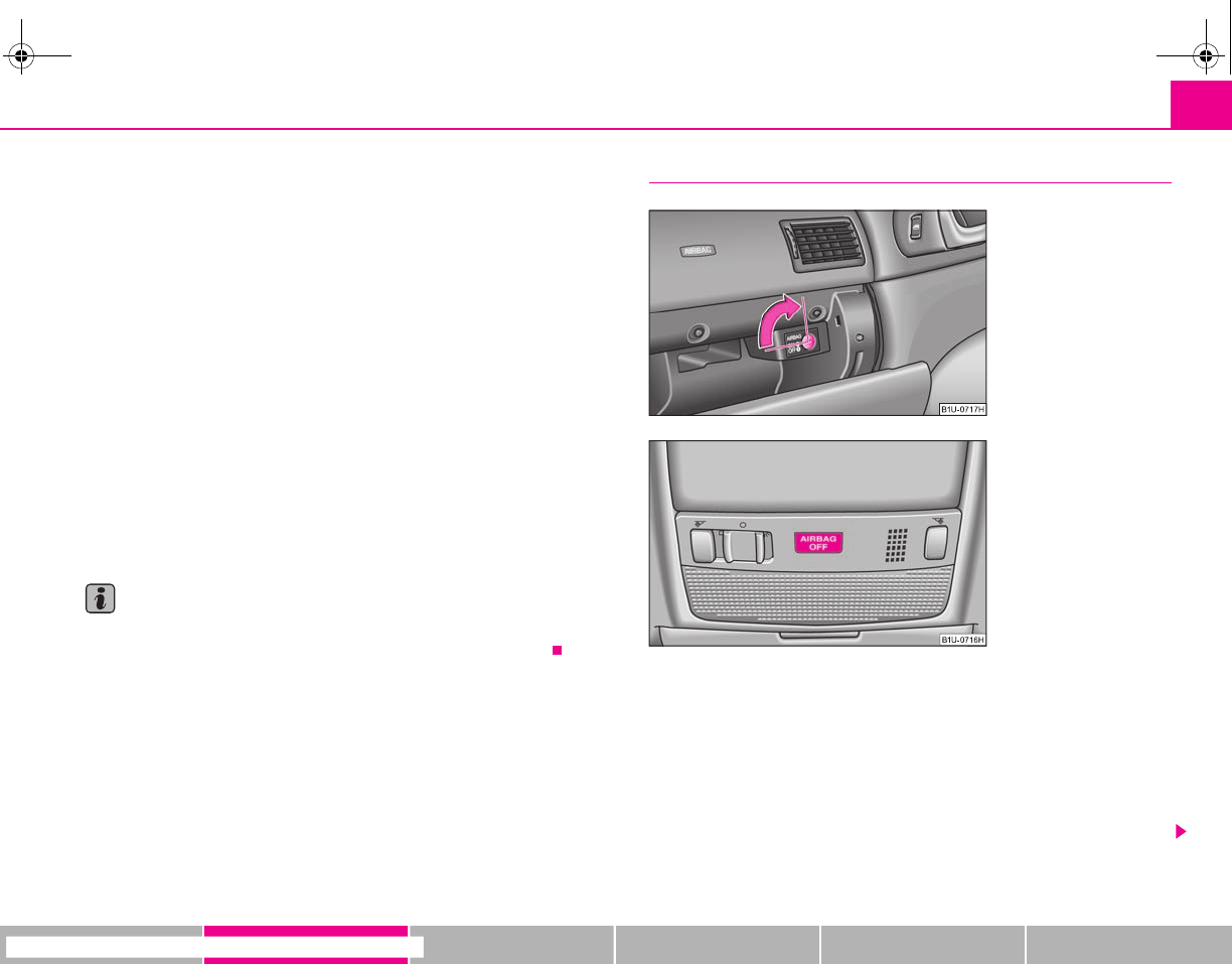
Airbag system 121
riving Tips General Maintenance Breakdown assistance Technical Data
•you are not able to maintain the distance of at least 25 cm between middle of
steering wheel and chest, despite the driver seat being correctly adjusted;
•special attachments are required in the area of the steering wheel because of a
physical disability;
•you have installed other seats (e.g. orthopaedic seats without side airbags).
Monitoring the airbag system
The functionality of the airbag system is also monitored electronically when one
airbag has been switched off.
If the airbag was switched off using diagnostic equipment:
•The airbag indicator light in the instrument cluster lights up for about 3 seconds
after switching on the ignition and then flashes after that for about 12 seconds.
Front passenger airbags switched off using the switch for front passenger
airbags* in storage compartment on the front passenger side:
•the airbag indicator light in the instrument cluster comes on for about 4
seconds each time the ignition is switched on;
•The deactivation of the airbag is indicated by the lighting up of the indicator
light at the front interior lighting of the vehicle ⇒page 121.
Note
A specialist garage will be able to advise you whether national legislation in your
country allows airbags in your vehicle to be deactivated, and which ones.
Switch for the front passenger airbag(s)*
The front passenger airbag as well as side airbag (if the vehicle is fitted
with side airbags) are switched off using the switch.
Deactivating an airbag
– Switch off the ignition.
– Turn the slot of the airbag switch using the key in the position OFF
⇒fig. 128 - (vertical position).
Fig. 128 Storage compart-
ment: Switch for the front
passenger airbag(s)
Fig. 129 Indicator light for a
switched off front seat
passenger airbag
s2g8.b.book Page 121 Tuesday, April 7, 2009 8:53 AM
Airbag system122
– Check whether the indicator light lights up in the lighting of
the interior of the vehicle (front) when the ignition is switched on
⇒page 121, fig. 129.
Switching on an airbag
– Switch off the ignition.
– Turn the slot of the airbag switch using the key in the position ON
⇒page 121, fig. 128 - (horizontal position).
– Check whether the indicator light does not light up in the
lighting of the interior of the vehicle (front) when the ignition is
switched on ⇒page 121, fig. 129.
The airbag should only be switched off under exceptional circumstances
⇒page 120.
Indicator light (airbag switched off)
The indicator light is located at the front interior lighting of the vehicle ⇒page 121,
fig. 129.
In cases where the front passenger airbag and also possibly the side airbag* are
switched off, the indicator light comes on about 4 seconds after the ignition is
switched on.
There is a system fault present in the airbag switch off ⇒ if the indicator light
flashes. Please have the car inspected immediately by a specialist garage.
WARNING
•The driver is responsible for whether the airbag is switched on or
switched off.
•Only switch off the airbag when the ignition is switched off! Otherwise a
fault can occur in the system for the airbag deactivation.
•If the warning light (airbag switched off) flashes:
−There is a risk of the front passenger airbag not being activated in the
event of an accident. Therefore do not use any child safety seats on the
front passenger seat.
−If the front passenger seat is occupied, there is a risk that the airbag is
deployed unexpectedly and thus the occupant of this seat may suffer
possible injuries.
−It is also important to have the system inspected without delay by a
specialist garage.
WARNING (continued)
s2g8.b.book Page 122 Tuesday, April 7, 2009 8:53 AM

Transporting children safely 123
riving Tips General Maintenance Breakdown assistance Technical Data
Transporting children safely
What you should know about transporting children!
An introduction to the subject
Accident statistics have revealed that children are generally more
safely transported on the rear seats than on the front passenger seat.
Children younger than 12 years of age should normally travel on the rear seat of the
vehicle (take note of any national legal provisions which differ from this). They
should be secured there by means of a child restraint system or by using the existing
seat belts depending on their age, body size and weight. The child seat should be
mounted behind the front passenger seat for safety reasons.
The physical principle of an accident does, of course, also apply to children
⇒page 109, “The physical principle of a frontal collision”. They differ from adults in
that their muscles and bone structure of children are not yet fully developed. Thus
children are exposed to increased risk of injury.
Children should be transported by using special child safety seats in order to
reduce this risk of injury.
Use only child safety seats which are officially approved and are suitable for chil-
dren and which comply with the ECE-R 44 standard, which classifies child safety
seats into 5 groups ⇒page 126, “Classification of child seats into groups”. Child
restraint systems which have been tested for conformity to ECE-R 44 standard have
a non-detachable test seal (a large E within a circle and below this the test number)
attached to the seat.
We recommend that you use child safety seats from the Škoda genuine accessories.
These child seats were developed and also tested for use in Škoda vehicles. They
fulfil the ECE-R 44 standard.
WARNING
Always comply with legal provisions and instructions from the relevant child
safety seat manufacturer when installing and using the child seat ⇒ in
“Important safety information regarding the use of child safety seats”.
Note
Any varying national legal regulations take priority over the information provided in
these instructions for use, or stated in this chapter.
Important safety information regarding the use of child safety
seats
Correct use of child safety seats considerably reduces the risk of
injury!
WARNING
•All the occupants of the car - in particular children - must wear a seat belt
when the car is moving.
•Children less than 1.50 m in height or younger than 12 years must not use
a normal seat belt without a child restraint system otherwise this may result
in injuries to the stomach and neck areas. Comply with the national legal
requirements.
•One should never carry children, and also not babies! - on one's lap.
•You can transport a child safely in a suitable child safety seat ⇒page 126,
“Child seat”!
•Only one child may be fastened with a seat belt into a child safety seat.
•Never leave the child sitting unattended in the seat.
•Certain outside climatic conditions can cause life-threatening tempera-
tures in the vehicle.
•Never allow your child to be transported in a vehicle without the use of a
suitable restraint system.
•Children should also never stand up in a vehicle or kneel on the seats
when the vehicle is moving. In the event of an accident the child will be
thrown through the vehicle and may as a result suffer fatal injuries, and also
injure other occupants.
s2g8.b.book Page 123 Tuesday, April 7, 2009 8:53 AM
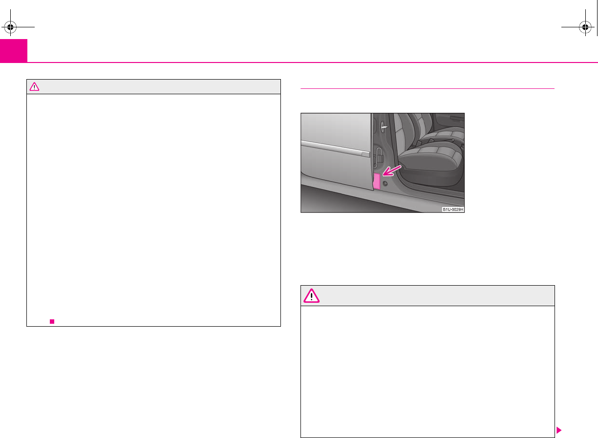
Transporting children safely124
•Children are exposed to an increased risk of injury in the event of an acci-
dent if they lean forward or adopt an incorrect seated position when the
vehicle is moving. This particularly applies to children who are transported
on the front passenger seat if the airbag system deploys in the event of an
accident. This can result in severe or even fatal injuries.
•It is important that the belt webbing is properly routed if the seat belts
are to offer their maximum protection ⇒page 110, “How are seat belts
correctly fastened?”. Pay particular attention to the information provided by
the manufacturer of the child safety seat regarding correct routing of the
belt. Seat belts which are not correctly adjusted can themselves cause inju-
ries even in minor accidents.
•Safety belts must be checked to ensure that they are running properly.
One should also ensure that the belt is not damaged by sharp-edged fittings.
•It is essential to always switch off the front passenger airbag and possibly
the side airbag* when attaching a child safety seat on the front passenger
seat where the child is seated with its back facing in direction of travel (in
some countries also when the child is facing the direction of travel)
⇒page 120. If this is not done, there is a risk of the child suffering severe or
even fatal injuries if the front passenger airbag is deployed. In certain coun-
tries national legal provisions also require that the side airbags be deacti-
vated. When transporting a child on the front passenger seat, please comply
with the appropriate national regulations regarding the use of child safety
seats.
Use of child safety seats on the front passenger seat
Child safety seats should always be attached to the rear seats.
We recommend, for safety reasons, that you always mount a child restraint systems
on the rear seats whenever possible. If you still decide, however, to use a child
safety seat on the front passenger seat then you must pay attention to the following
warnings in connection with the use of the airbag system on the front passenger
seat.
WARNING
•Warning - particular hazard! Never use a child safety seat on the front
passenger seat in which the child is seated with its back facing the direction
of travel. This child safety seat is positioned in the deployment area of the
front passenger airbag. The airbag may cause the child severe, or even fatal
injuries, in the event of it being deployed.
•This is also clearly stated on the sticker which is located on the centre
column of the body on the front passenger side ⇒fig. 130. The sticker is
visible upon opening the front passenger door. For some countries, the
sticker is also affixed to the sun visor of the front passenger.
•It is essential to always switch off the front passenger airbag or the side
passenger airbag* as well if you nevertheless wish to use a child safety seat
on the front passenger seat where the child is seated with its back facing in
direction of travel (in some countries also when the child is facing the direc-
WARNING (continued)
Fig. 130 Sticker on the centre
column of the body on the
front passenger side.
s2g8.b.book Page 124 Tuesday, April 7, 2009 8:53 AM
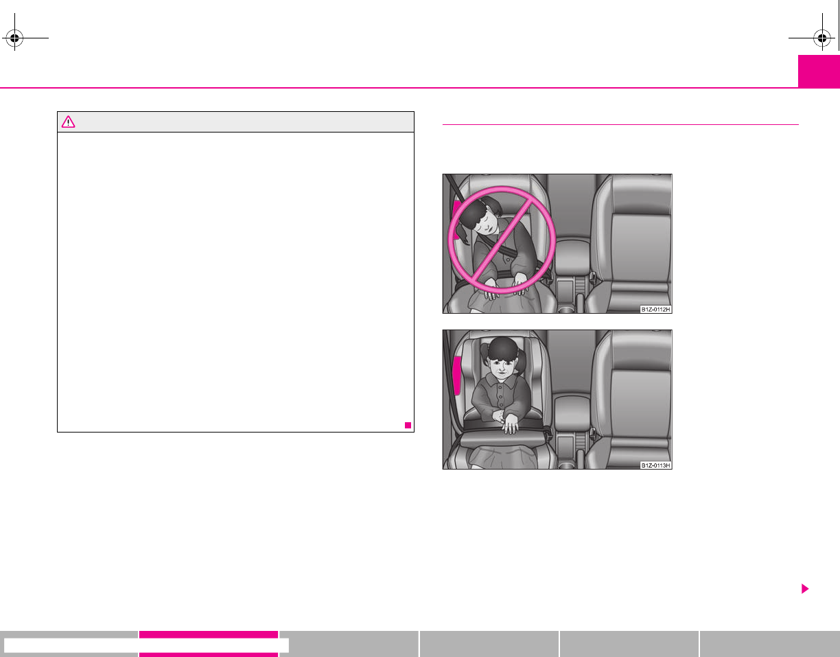
Transporting children safely 125
riving Tips General Maintenance Breakdown assistance Technical Data
tion of travel) ⇒page 120, “Deactivating an airbag”. If this is not done, there
is a risk of the child suffering severe or even fatal injuries if the front
passenger airbag is deployed. In certain countries national legal provisions
also require that the side airbags be deactivated. When transporting a child
on the front passenger seat, please comply with the appropriate national
regulations regarding the use of child safety seats.
•If the front passenger airbag has been switched off by a specialist garage
using the vehicle system tester, the side passenger airbag* remains switched
on. In certain countries national legal provisions require that besides the
front passenger airbag also the side airbag is deactivated. Please comply
with any differing national legal regulations regarding the use of child safety
seats.
•If a child safety seat in which the child faces in the direction of travel is
used on the front passenger seat, the front passenger seat must be moved
back fully. For vehicles with height adjustable front passenger seat, the seat
must be put in the highest position.
•If this is not done, a child seated on the front passenger seat may suffer
severe or even fatal injuries if the front passenger airbag or airbags are
deployed. Have the airbag (or airbags) deactivated if necessary ⇒page 120.
•You should have the front passenger airbag (or airbags) reactivated just
as soon as you no longer use a child safety seat on the front passenger seat.
Child safety and side airbag*
Children must never be seated in the deployment area of side
airbags.
In the event of a side collision, the side airbags offer the vehicle occupants
enhanced protection.
The side airbags are inflated in fractions of a second in order to be able to provide
this protection ⇒page 119, “Function of the side airbags”.
An airbag inflating develops such a strong force that an occupant who has not
adopted an upright seated position may suffer injuries from the airbag or as a result
of objects which are located within the deployment area of the side airbag.
WARNING (continued)
Fig. 131 Seated position of
an unprotected child at risk
from side airbag
Fig. 132 Child properly
protected by safety seat
s2g8.b.book Page 125 Tuesday, April 7, 2009 8:53 AM
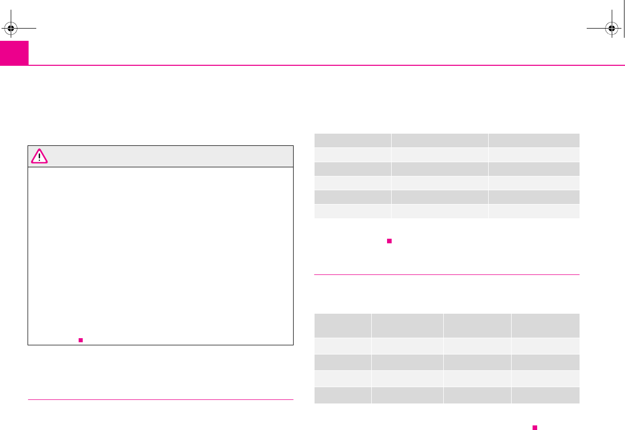
Transporting children safely126
This applies particularly to children if they are not transported in accordance
with legal requirements.
The child is protected when seated in a child safety seat matching its age. Adequate
room is available between the child and the deployment area of the side airbag and
head airbag. The airbag offers optimal protection.
WARNING
•It is essential to always switch off the front passenger airbag and possibly
the side airbag* when attaching a child safety seat on the front passenger
seat where the child is seated with its back facing in direction of travel (in
some countries also when the child is facing the direction of travel)
⇒page 120. If this is not done, there is a risk of the child suffering severe or
even fatal injuries if the front passenger airbag is deployed. In certain coun-
tries national legal provisions also require that the side airbags be deacti-
vated. When transporting a child on the front passenger seat, please comply
with the appropriate national regulations regarding the use of child safety
seats.
•When transporting a child on the front passenger seat, please comply
with the appropriate national regulations regarding the use of child safety
seats.
•Children must never be seated with their head in the deployment area of
the side airbag - risk of injury!
•Do not place any objects within the deployment area of the side airbag -
risk of injury!
Child seat
Classification of child seats into groups
Only child safety seats which have an official approval and are suit-
able for the child, may be used.
ECE-R 44 standard applies to child safety seats. ECE-R means: Standard Economic
Commission of Europe - Regulation.
Child safety seats which have been tested for conformity to ECE-R 44 standard have
a non-detachable test seal (a large E within a circle and below this the test number)
attached to the seat.
Child safety seats are classified in 5 groups:
Children of more than 150 cm in height may use the seat belts fitted to the vehicle
without a seat bolster.
Use of child safety seats
An overview of the usefulness of child seats on each of the seats according to the
EG guidelines 77/541 and ECE 44 standard:
Universal category - seat is suitable for all approved types of child safety seats.
The seat can be fitted with fixing eyes for the “ISOFIX*”system.
Group Weight
00 - 10 kg ⇒page 127
0+ up to 13 kg ⇒page 127
19 - 18 kg ⇒page 127
215 - 25 kg ⇒page 128
322 - 36 kg ⇒page 128
Child seat
of the group
Front passenger
seat
Rear seat
outside
Rear seat
middle
0
0+
1
2 and 3
A
U
A
+
A
U
A
+
A
U
A
U
A
+
A
U
A
+
A
U
A
U
A
+
A
U
A
+
A
U
A
U
A
U
A
U
A
U
A
+
s2g8.b.book Page 126 Tuesday, April 7, 2009 8:53 AM
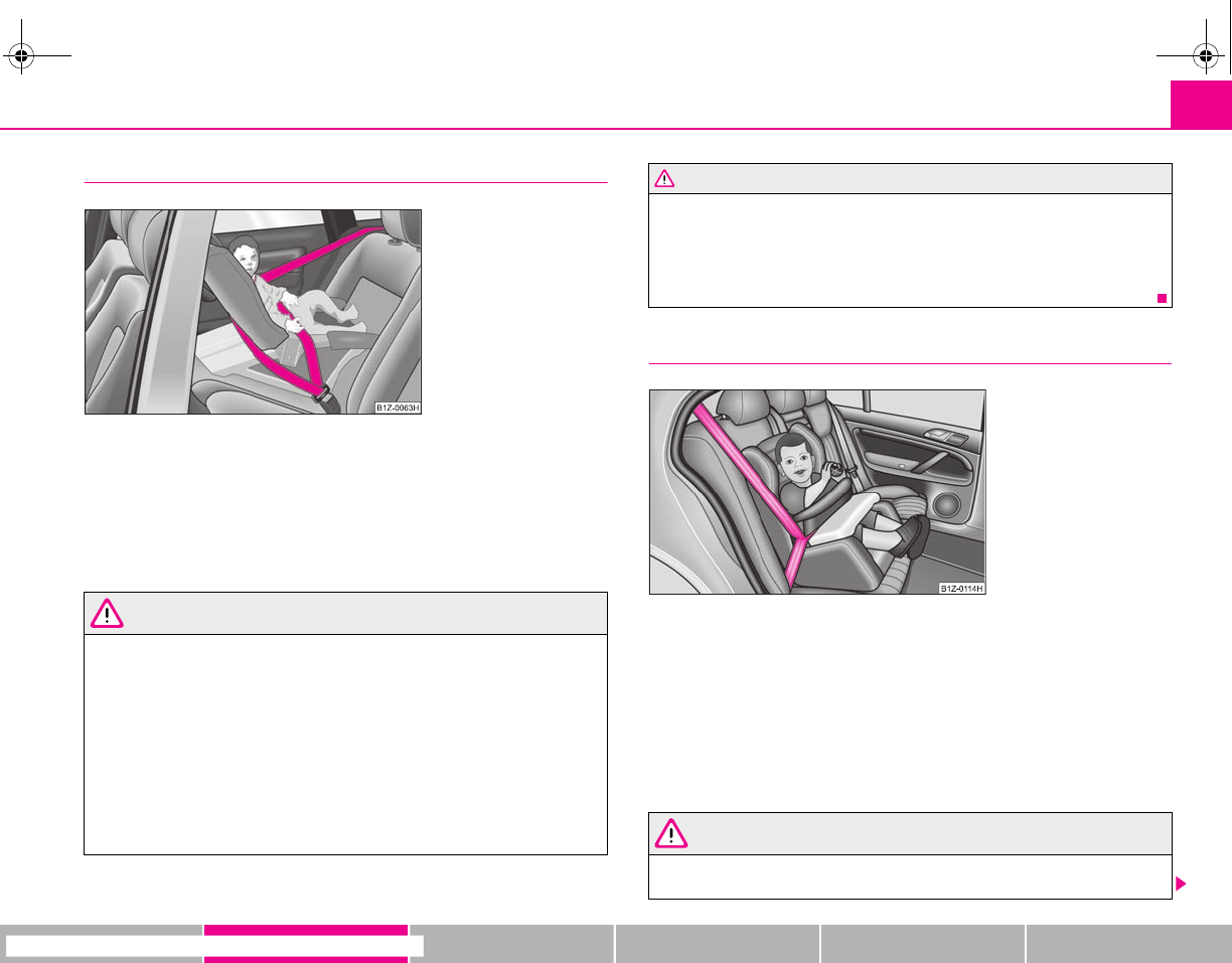
Transporting children safely 127
riving Tips General Maintenance Breakdown assistance Technical Data
Child seats of group 0/0+
The optimal solution for babies of up to about 9 months old weighing up to 10 kg
or babies up to about 18 months old weighing up to 13 kg is a child safety seat
which can be adjusted into the reclining position ⇒fig. 133.
In view of the fact that such child seats are installed that the child is seated with its
back facing the direction of travel, they must not be used on the front passenger
seat⇒page 124, “Use of child safety seats on the front passenger seat”.
WARNING
•It is essential to always switch off the front passenger airbag (airbags)
when attaching in exceptional circumstances a child safety seat on the front
passenger seat where the child is seated with its back facing in direction of
travel (in some countries also when the child is facing the direction of travel).
−in a specialist garage
−or by using the switch for the front passenger airbag* ⇒page 121.
•In certain countries national legal provisions require that besides the
front passenger airbag also the front passenger side airbag is deactivated.
Please comply with any differing national legal regulations regarding the
use of child safety seats.
•If this is not done, a child seated on the front passenger seat may suffer
severe or even fatal injuries if the front passenger airbag or airbags are
deployed.
•You should have the front passenger airbag (or airbags) reactivated just
as soon as you no longer use a child safety seat on the front passenger seat.
Child safety seats in Group 1
Child seats in Group 1 are for babies and small children up to 4 years of age with a
weight of between 9 and 18 kilograms. It is best for children in the lower range of
this group, to use a child seat which allows the child to sit with its back to the direc-
tion of travel. It is best for children in the upper range of the Group 0+, to use a child
seat which allows the child to sit ⇒fig. 134 in the direction of travel.
Child safety seats in which the child is seated with its back facing the direction of
travel, must not be used on the front passenger seat ⇒page 124, “Use of child
safety seats on the front passenger seat”.
WARNING
•It is essential to always switch off the front passenger airbag (airbags)
when attaching in exceptional circumstances a child safety seat on the front
Fig. 133 Child seats of group
0/0+
WARNING (continued)
Fig. 134 Child seat with
padded table in Group 1
installed on rear seat bench
facing the direction of travel
s2g8.b.book Page 127 Tuesday, April 7, 2009 8:53 AM
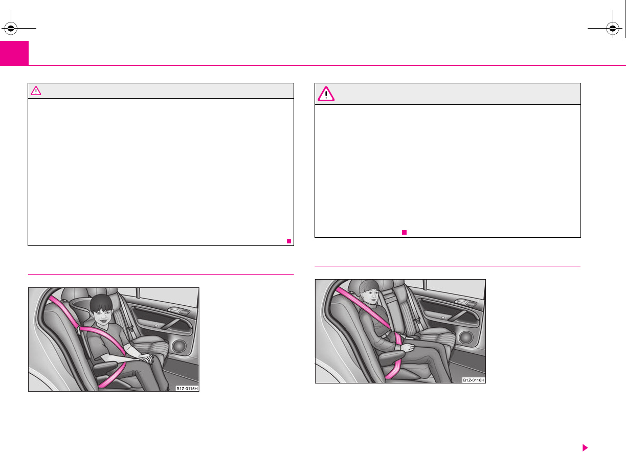
Transporting children safely128
passenger seat where the child is seated with its back facing in direction of
travel (in some countries also when the child is facing the direction of travel).
−in a specialist garage
−or by using the switch for the front passenger airbag* ⇒page 121.
•In certain countries national legal provisions require that besides the
front passenger airbag also the front passenger side airbag is deactivated.
Please comply with any differing national legal regulations regarding the
use of child safety seats.
•If this is not done, a child seated on the front passenger seat may suffer
severe or even fatal injuries if the front passenger airbag or airbags are
deployed.
•You should have the front passenger airbag (or airbags) reactivated just
as soon as you no longer use a child safety seat on the front passenger seat.
Child safety seats in Group 2
For children up to about 7 years of age weighing between 15 and 25 kg the optimal
solution is a child safety seat in combination with the three-point seat belt
⇒fig. 135.
WARNING
•When transporting a child on the front passenger seat, please comply
with the appropriate national regulations regarding the use of child safety
seats. If required, the airbag has to be deactivated,
−in a specialist garage
−or by using the switch for the front passenger airbag* ⇒page 121.
•The shoulder part of the seat belt must run approximately across the
middle of the shoulder and fit snugly against the chest. It must on no account
run across the neck. The lap part of the seat belt must run across the pelvis
and fits snugly; it must not run over the belly. Tighten the belt webbing over
your hip if necessary.
•Please comply with any differing national legal regulations regarding the
use of child safety seats.
Child safety seats in Group 3
For children of about 7 years of age weighing between 22 and 36 kg and of a height
of less than 150 cm, the optimal solution is a child safety seat (seat bolster) in
combination with the three-point seat belt ⇒fig. 136.
Children of more than 150 cm in height may use the seat belts fitted to the vehicle
without a seat bolster.
WARNING (continued)
Fig. 135 Child seat in Group
2 installed on the rear seat
facing the direction of travel
Fig. 136 Child seat in Group
3 installed on the rear seat
facing the direction of travel
s2g8.b.book Page 128 Tuesday, April 7, 2009 8:53 AM
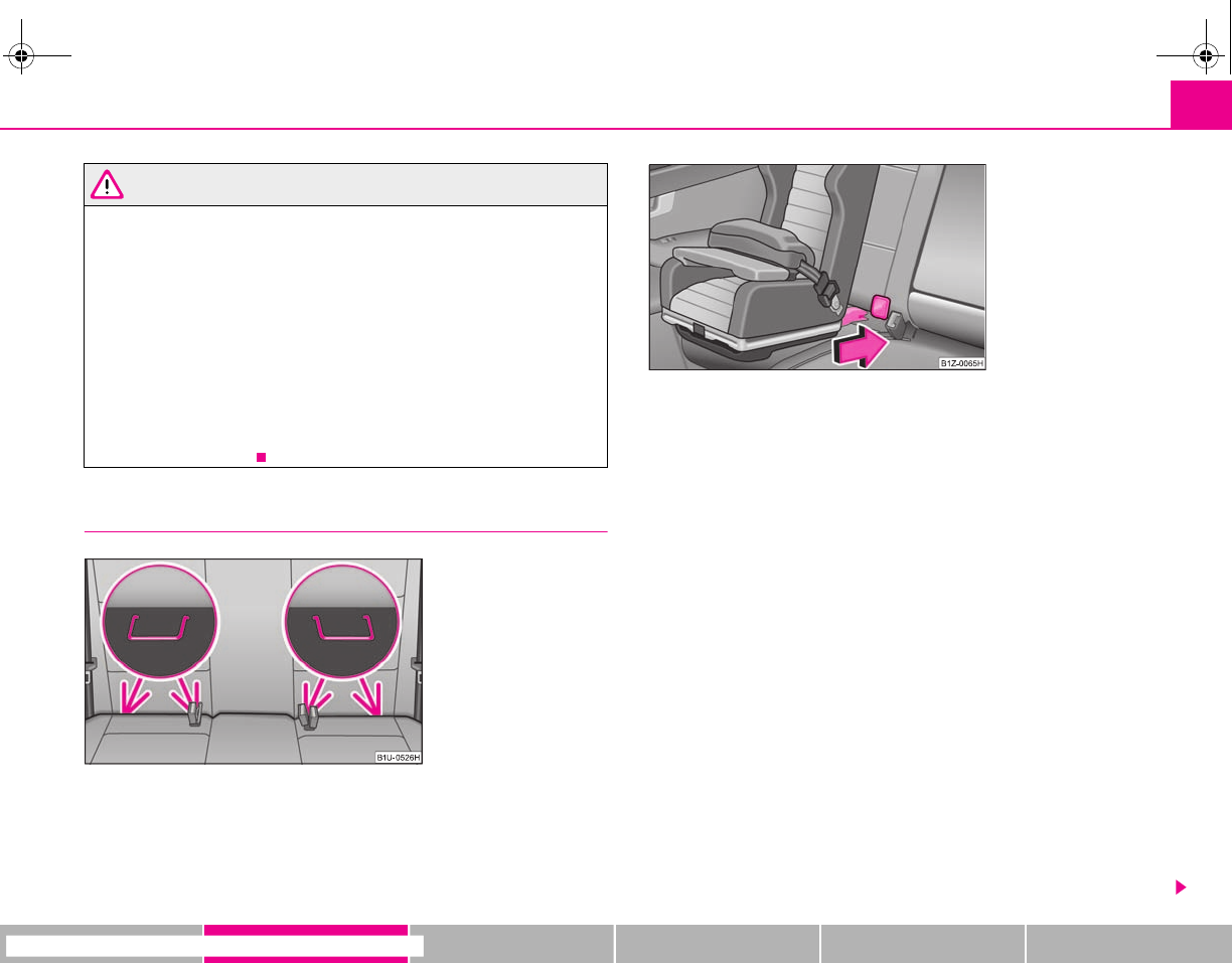
Transporting children safely 129
riving Tips General Maintenance Breakdown assistance Technical Data
WARNING
•When transporting a child on the front passenger seat, please comply
with the appropriate national regulations regarding the use of child safety
seats. If required, the airbag has to be deactivated,
−in a specialist garage
−or by using the switch for the front passenger airbag* ⇒page 121.
•The shoulder part of the seat belt must run approximately across the
middle of the shoulder and fit snugly against the chest. It must on no account
run across the neck. The lap part of the seat belt must run across the pelvis
and fits snugly; it must not run over the belly. Tighten the belt webbing over
your hip if necessary.
•Please comply with any differing national legal regulations regarding the
use of child safety seats.
Attaching a child seat using the “ISOFIX” system
There are two locking eyes between the rear exterior seat backrest and
the surface of the seat itself on both sides for fixing the ISOFIX system
child seat in place. One can mount a child safety seat using the ISOFIX
system quickly, easily and reliably. The installation must be carried out
according to the supplied instructions. The seat must click into place
audibly when installing.
Install child seat
– Insert the mounting funnels onto the locking eyes between the seat
backrest and the seat cushion ⇒fig. 137.
– Push the notched arms of the child seat over the mounting funnels
into the locking eyes, until it is heard to lock ⇒fig. 138.
–Pull on both sides of the child seat!
One can mount a child safety seat using the “ISOFIX” system quickly, easily and reli-
ably. Please pay close attention to instructions from the manufacturer of the child
safety seat when installing and removing the seat.
Child seats fitted with the “ISOFIX” system can only be mounted and fixed in a
vehicle fitted with an “ISOFIX” system when these child seats have been released for
this type of vehicle according to the ECE-R 44 standard.
You can obtain child seats with the “ISOFIX” attachment system from specialist
garages who will also installed it as well.
Fig. 137 Locking eyes
(ISOFIX system)
Fig. 138 The ISOFIX child
seat is pushed into the
mounting funnels
s2g8.b.book Page 129 Tuesday, April 7, 2009 8:53 AM
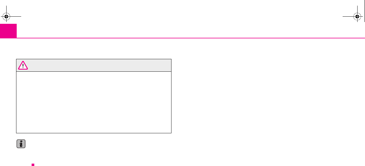
Transporting children safely130
Complete installation instructions are enclosed with the child safety seat.
WARNING
•The locking eyes have just been developed for child safety seats which
use the “ISOFIX” system. You should therefore never attach other child
safety seats, seat belts or objects to the locking eyes - hazard!
•Ask a specialist garage whether a child seat which you bought for
another vehicle is recommended for use in your vehicle before using a child
seat with “ISOFIX” system.
•Certain child seats which use the “ISOFIX” system can be attached with
standard three-point seat belts. Please pay close attention to instructions
from the manufacturer of the child safety seat when installing and removing
the seat.
Note
•Child seats which use the “ISOFIX” system are currently available for children
weighing from 9 up to 18 kg. This corresponds to an age range of from 9 months to
4 years.
s2g8.b.book Page 130 Tuesday, April 7, 2009 8:53 AM
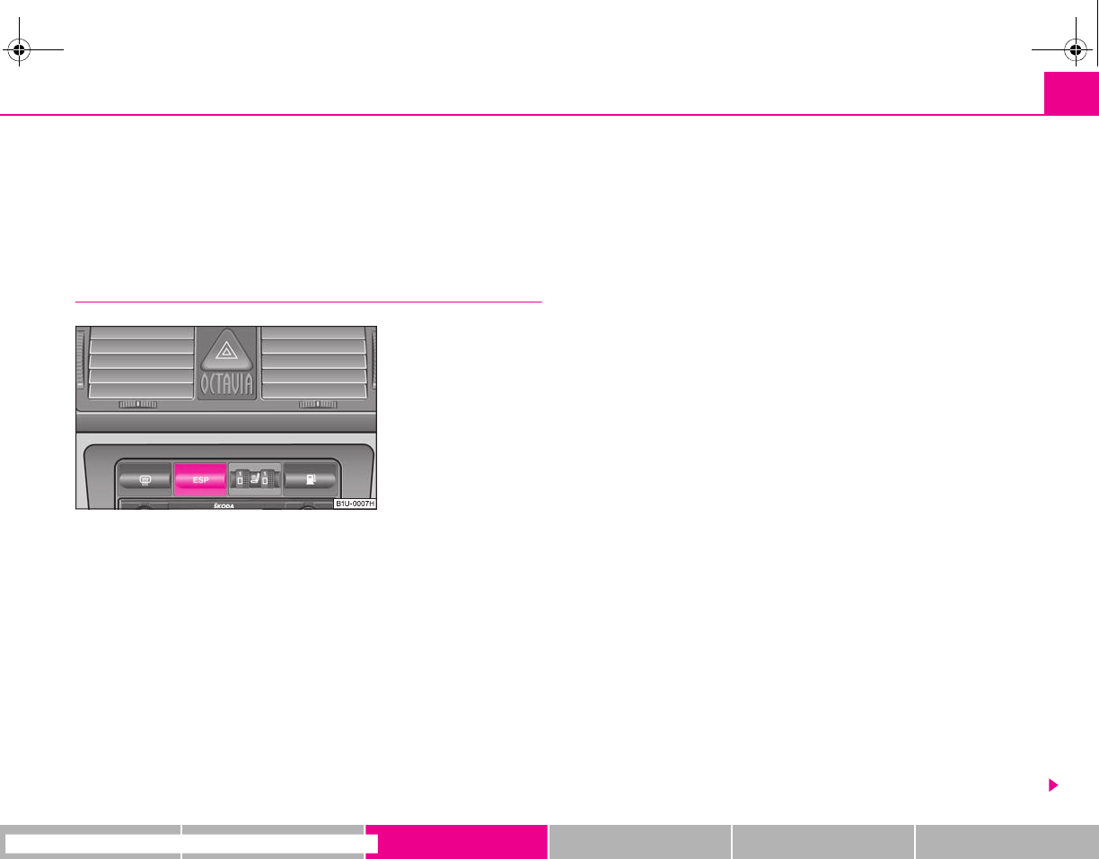
Intelligent Technology 131
riving Tips General Maintenance Breakdown assistance Technical Data
Driving Tips
Intelligent Technology
Electronic stability programme (ESP)*
General
General
The ESP aids you maintain control of your vehicle in situations in borderline driving
situations such as when negotiating a curve too fast. The risk of skidding is reduced
and your vehicle thus offers greater driving stability depending on the conditions of
the road surface. This occurs at all speeds.
The following systems are integrated into the electronic stability programme:
•Electronic Differential Lock (EDL),
•Traction control system (TCS),
•Antilock brake system (ABS),
•Brake Assist.
Operating principle
The ESP switches on automatically when the engine is started and then conducts a
self-test. The ESP control unit processes data from the individual systems. It also
processes additional measurement data which are supplied by highly sensitive
sensors: the rotational velocity of the vehicle about its vertical axis, the lateral accel-
eration of the vehicle, the braking pressure and the steering angle.
The direction which the driver wishes to take is determined based on the steering
angle and the speed of the vehicle and is constantly compared with the actual
behaviour of the vehicle. If differences exist, such as the vehicle beginning to skid,
the ESP will automatically brake the appropriate wheel.
The car is stabilised again by the forces which take effect when the wheel is braked.
Intervention into the brake system takes place primarily on the outer front wheel of
a vehicle which tends to oversteer (tendency for the rear of the vehicle to break
away) while occurs this is on the inner rear wheel of a vehicle which tends to under-
steer (tendency to shift out of the curve). This braking control cycle is accompanied
by noises.
The ESP operates in combination with the ABS ⇒page 135, “Antilock brake system
(ABS)*”. If there is a fault in the ABS system, the ESP also does not operate.
The ESP warning light ⇒page 33 lights up in the instrument cluster when there is a
fault on the ESP.
Switching off
You can switch the ESP off and on again as you wish, by pressing the button
⇒fig. 139. The ESP warning light ⇒page 33 lights up in the instrument cluster
when the ESP is switched off.
The ESP should normally always be switched on. It may be good practice in certain
exceptional cases, such as when you wish to have wheel slip, to switch off the
system.
Examples:
Fig. 139 ESP switch
s2g8.b.book Page 131 Tuesday, April 7, 2009 8:53 AM
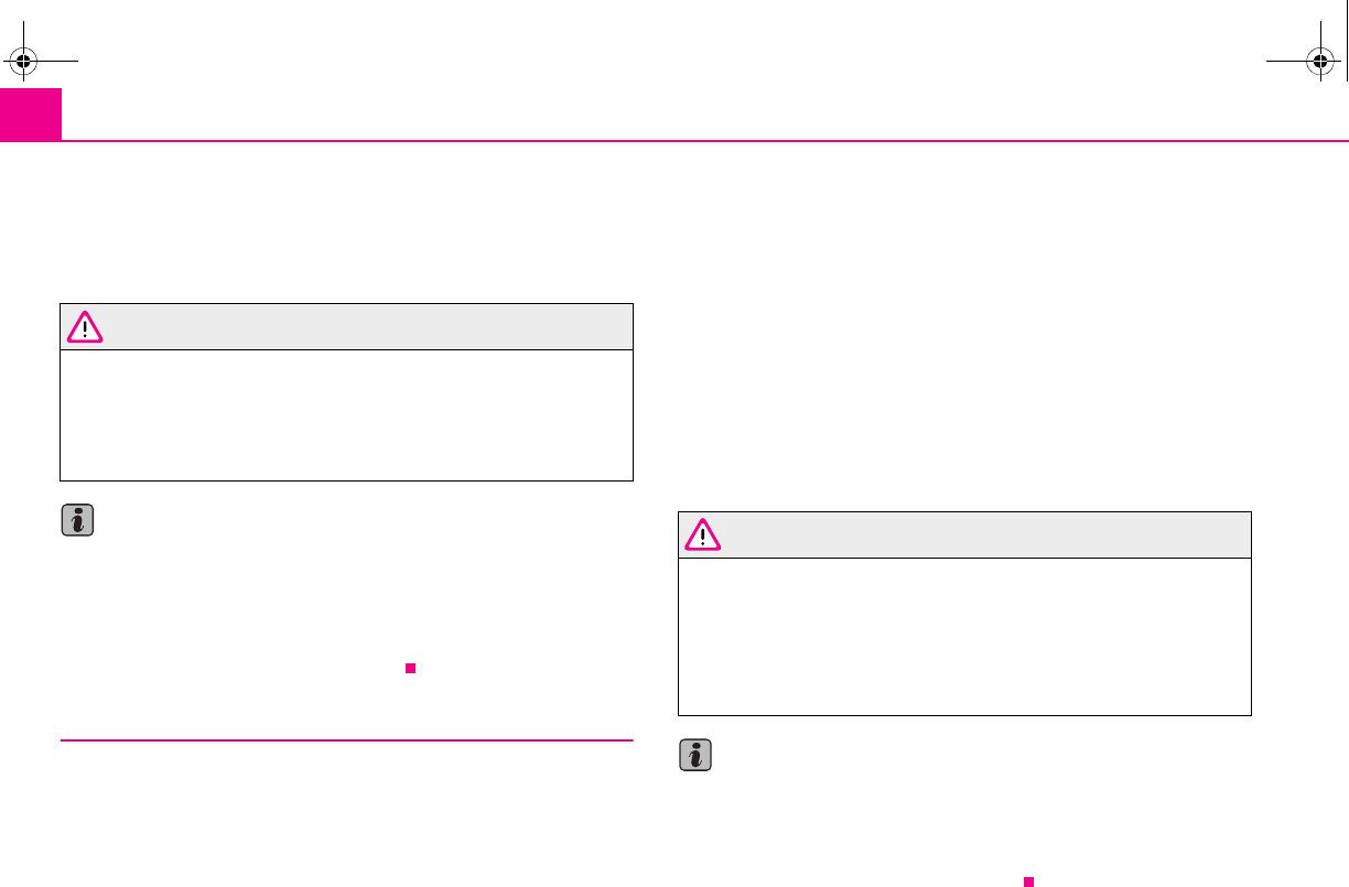
Intelligent Technology132
•when driving with snow chains
•when driving in deep snow or on a loose surface
•when it is necessary to rock a vehicle when it has become stuck.
then you should switch on the ESP again.
WARNING
It is also not possible for the ESP to overcome the physical limits of the
vehicle. Even if a vehicle fitted with ESP you should still always adapt your
style of driving to the condition of the road surface and the traffic situation.
This particularly applies when driving on slippery and wet roads. The
increased safety offered must not tempt you to take greater risks than other-
wise - risk of an accident!
Note
•All four wheels must be fitted with the same tyres in order to achieve problem-
free operation of the ESP. Differing rolling circumferences of the tyres can lead to an
undesirable reduction in the engine output.
•Changes to vehicle (e.g. on engine, on the brakes, on chassis or another combi-
nation of tyres and wheels) can influence the function of the ESP ⇒page 179,
“Accessories, changes and replacement of parts”.
Electronic Differential Lock (EDL)*
The electronic differential lock prevents an individual wheel from
slipping.
Vehicles fitted with ABS* can be equipped with electronic differential lock (EDL).
General
The EDL makes it much easier, and sometimes at all possible, to start off, accelerate
and climb a steep hill when the conditions of the road surface are unfavourable.
Operating principle
The EDL is activated automatically, that is without any action on the part of the
driver. It monitors the speeds of the driven wheels with the aid of the ABS sensors.
Should only one drive wheel begin spinning on a slippery surface there will be an
appreciable difference in the speed of the driven wheels. The EDL function brakes
the slipping wheel and the differential transmits a greater driving force to the other
driven wheel. This control process is also accompanied by noises.
Overheating of the brakes
The EDL switches off automatically if unusually severe stresses exist in order to
avoid excessive heat generation in the disc brake on the wheel which is being
braked. The vehicle can continue to be driven and has the same characteristics as a
vehicle not fitted with EDL.
The EDL switches on again automatically as soon as the brake has cooled down.
WARNING
•Carefully depress the accelerator when accelerating on uniformly slip-
pery road surfaces, such as ice and snow. The driven wheels might still spin
despite the EDL and affect the stability of the vehicle - risk of an accident!
•You should always adapt your style of driving to the condition of road
surface and to the traffic situation even when your vehicle is fitted with EDL.
The increased safety offered must not tempt you to take greater risks than
otherwise - risk of an accident!
Note
•If the ABS warning light comes on, this may also indicate a fault in the EDL.
Please have the vehicle inspected as soon as possible by a specialist garage.
•Changes to vehicle (e.g. on engine, on the brakes, on chassis or another combi-
nation of tyres and wheels) can influence the function of the EDL ⇒page 179,
“Accessories, changes and replacement of parts”.
s2g8.b.book Page 132 Tuesday, April 7, 2009 8:53 AM
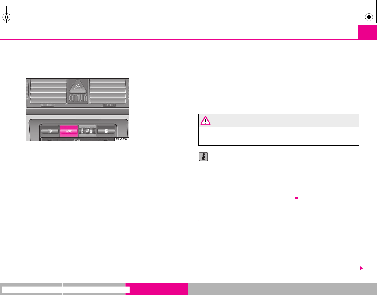
Intelligent Technology 133
riving Tips General Maintenance Breakdown assistance Technical Data
Traction control system (TCS)
The traction control system prevents the driven wheels from spinning
when accelerating.
General
The TCS makes it much easier, and sometimes at all possible, to start off, accelerate
and climb a steep hill when the conditions of the road surface are unfavourable.
Operating principle
The TCS switches on automatically when the engine is started and then conducts a
self-test. The system monitors the speeds of the driven wheels with the aid of the
ABS sensors. If the wheels are spinning, the force transmitted to the road surface is
automatically adapted by reducing the engine speed. This occurs at all speeds.
The TCS operates in combination with the ABS ⇒page 135, “Antilock brake system
(ABS)*”. The TCS will not function if a fault exists in the ABS system.
The TCS warning light ⇒page 33 lights up in the instrument cluster when there is a
fault on the TCS.
Switching off
You can switch the TCS off and on again as you wish by pressing the button
⇒fig. 140. The TCS warning light ⇒page 33 lights up in the instrument cluster
when the TCS is switched off.
The TCS should normally always be switched on. It may be good practice in certain
exceptional cases, such as when you wish to have wheel slip, to switch off the
system.
Examples:
•when driving with snow chains
•when driving in deep snow or on a loose surface
•when it is necessary to rock a vehicle when it has become stuck.
then you should switch on the TCS again.
WARNING
You should always adjust your style of driving to the conditions of the road
surface and the traffic situation. The increased safety offered must not tempt
you to take greater risks than otherwise - risk of an accident!
Note
•All four wheels must be fitted with the same tyres in order to achieve problem-
free operation of the TCS. Differing rolling circumferences of the tyres can lead to
an undesirable reduction in the engine output.
•Changes to vehicle (e.g. on engine, on the brakes, on chassis or another combi-
nation of tyres and wheels) can influence the function of the TCS ⇒page 179,
“Accessories, changes and replacement of parts”.
Brakes
What has a negative effect on braking efficiency?
Wear-and-tear
Wear-and-tear to the brake pads is greatly dependent on the operating conditions
of the vehicle and your style of driving. Particularly if you drive a great deal in towns
and over short distances or if you adopt a sporty style of driving, it may be neces-
sary to have the thickness of the brake pads inspected at a specialist garage
between the service inspections.
Fig. 140 TCS switch
s2g8.b.book Page 133 Tuesday, April 7, 2009 8:53 AM
Intelligent Technology134
Wet roads or road salt
There may be a certain delay before the brakes take full effect under certain condi-
tions such as when driving through water, during heavy rain showers or after the
vehicle has been washed in an automatic vehicle wash, since the brake discs and
brake pads may be moist or even have a coating of ice on them in winter. You
should dry the brakes as soon as possible by applying and releasing the brakes
several times.
There also may be a certain delay before the full braking efficiency is available when
driving on roads which have been treated with road salt if you have not used the
brakes for some considerable time beforehand. The layer of salt on the brake discs
and brake pads must first be rubbed off when you apply the brakes.
Corrosion
Corrosion on the brake discs and dirt on the bake pads occur if the vehicle has been
parked for a long period and if you do not make much use of the braking system.
We recommend cleaning the brake discs by firmly applying the brakes at a fairly
high speed if you do not make much use of the braking system or if surface corro-
sion is present ⇒.
Faults in the brake surface
If you notice that the braking distance has suddenly become longer and that the
brake pedal can be depressed further, it is possible that a brake circuit of the dual-
circuit brake system has failed. Drive, in such cases, to the nearest specialist garage
without delay in order to have the problem rectified. Drive at a reduced speed while
on your way to the dealer and adapt your style of driving to the higher brake pedal
pressure required.
Low brake fluid level
An insufficient level of brake fluid may result in problems in the brake system. The
level of the brake fluid is monitored electronically ⇒page 34, “Brake system ”.
WARNING
•Only apply the brakes for the purpose of drying and cleaning the brake
discs if the traffic conditions permit this. Do not place any other road users
in jeopardy.
•When retrospectively mounting a front spoiler, solid wheel hubs etc. one
must ensure that the air supply to the front wheel brakes is not reduced
otherwise the braking system could run too hot.
•Allow for the fact that new brake pads do not achieve their full braking
efficiency until approximately 200 kilometres. New brake pads must be first
“run in” before they develop their optimal friction force. You can, however,
compensate for this slightly reduced braking force by increasing the pres-
sure on the brake pedal. This guideline also applies to any new brake pads
installed at a future date.
Caution
•Never allow the brakes to rub by applying slight pressure if you do not wish to
brake the vehicle. This causes the brakes to overheat and can also result in a longer
braking distance and excessive wear.
•Before negotiating a steep downhill section, reduce your speed, shift down into
the next lower gear. This enables you to make full use of the braking power of the
vehicle and reduces the strain on the brakes. Any additional braking should be done
intermittently, not continuously.
Brake booster
The brake booster boosts the pressure which you generate with the brake pedal.
The necessary pressure is only generated when the engine is running.
WARNING
•Never switch off the engine before the vehicle is stationary.
•The brake booster only operates when the engine is running. Greater
physical effort for braking is required when engine is switched off. Because
if you do not stop as normal, this can cause an accident and severe injuries.
WARNING (continued)
s2g8.b.book Page 134 Tuesday, April 7, 2009 8:53 AM
Intelligent Technology 135
riving Tips General Maintenance Breakdown assistance Technical Data
Antilock brake system (ABS)*
ABS prevents the wheels locking when braking.
General
The ABS contributes significantly to enhancing the active safety of your vehicle.
Compared to a vehicle not fitted with the ABS brake system, you are able to retain
optimal steering ability even during a full brake application on a slippery road
surface because the wheels do not lock up.
You must not expect, however, that the braking distance will be shorter under all
circumstances as a result of the ABS. The braking distance for example on gravel
and fresh snow, when you should anyway be driving slowly and cautiously, will be
longer.
Operating principle
The brake pressure will be reduced on a wheel which is rotating at a speed which is
too low for the speed of the vehicle and tending to lock. This control cycle is notice-
able from a pulsating movement of the brake pedal which is accompanied by
noises. This is consciously intended to provide the driver with the information that
the wheels are tending to lock (ABS control range). You must always keep the brake
pedal depressed to enable the ABS to optimally control the brake application in this
braking range. Never interrupt the application of the brakes!
WARNING
•The ABS can also not overcome the physical limits of your vehicle. Please
do not forget this, particularly when driving on icy or wet road surfaces. If the
ABS is operating within the control range, adapt your speed immediately to
the conditions of the road surface and the traffic situation. The increased
safety offered by the ABS must not tempt you to take greater risks than
otherwise - risk of an accident!
•The normal braking system is still fully functional if there is an ABS fault.
Visit a specialist garage as quickly as possible and adjust your style of driving
to take account of the ABS fault in the meantime since you will not know the
extent of the fault and in how far the braking efficiency is affected.
Note
•A warning light comes on if a fault occurs in the ABS system ⇒page 32.
•Changes to vehicle (e.g. on engine, on the brakes, on chassis or another combi-
nation of tyres and wheels) can influence the function of the ABS ⇒page 179,
“Accessories, changes and replacement of parts”.
Brake Assist*
During a severe brake application (e.g. if a hazard exists), the Brake Assist increases
the braking force and thus makes it possible to rapidly produce the pressure
required in the brake system.
The majority of drivers do apply the brakes in good time in dangerous situations,
but do not depress the brake pedal with sufficient pressure. Consequently, it is not
possible for the vehicle to achieve its maximum deceleration and the vehicle covers
a greater distance than necessary.
The Brake Assist is activated by the very quick operation of the brake pedal. In such
cases, a much greater braking pressure exists than during a normal brake applica-
tion. This makes it possible, even with a relatively low resistance of the brake pedal,
to produce an adequate pressure in the brake system in the shortest possible time,
which is required for maximum deceleration of the vehicle. You must apply the
brake pedal firmly and hold it in this position in order to achieve the shortest
possible braking distance.
The Brake Assist is able to help you achieve a shorter braking distance in emergency
situations by rapidly producing the pressure required in the brake system. It fully
exploits the attributes of the ABS. After you release the brake pedal, the function of
the Brake Assist is automatically switched off and the brakes operate in the normal
way.
WARNING
•The Brake Assist is also not able to overcome the physical limits of your
vehicle in terms of the braking distance required.
s2g8.b.book Page 135 Tuesday, April 7, 2009 8:53 AM
Intelligent Technology136
•Adapt your speed to the conditions of the road surface and to the traffic
situation.
•The increased safety offered by the Brake Assist must not tempt you to
take a greater safety risk than otherwise.
WARNING (continued)
s2g8.b.book Page 136 Tuesday, April 7, 2009 8:53 AM
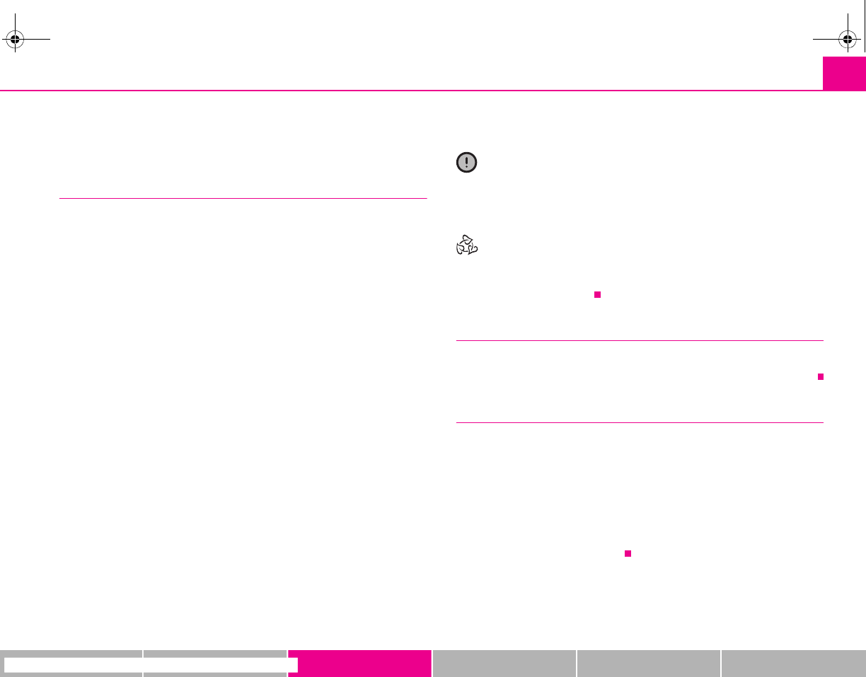
Driving and the Environment 137
riving Tips General Maintenance Breakdown assistance Technical Data
Driving and the Environment
The first 1 500 kilometres and then afterwards
A new engine
The engine has to be run in during the first 1 500 kilometres.
Up to 1 000 kilometres
– Do not drive faster than 3/4 of the maximum speed of the gear in use,
that is 3/4 of the maximum permissible engine speed.
– Do not use full throttle.
– Avoid high engine revolutions.
– Do not tow a trailer.
From 1 000 up to 1 500 kilometres
– Increase the power output of the engine gradually up to the full
speed of the gear engaged, that is up to the maximum permissible
engine revolutions.
During the first operating hours the engine has higher internal friction than later
until all of the moving parts have harmonized. The driving style which you adopt
during the first approx.1 500 kilometres plays a decisive part in the success of
running in your vehicle.
You should not drive at unnecessarily high engine revolutions even after the
running-in period is complete. The maximum permissible engine speed is marked
by the beginning of the red zone on the scale of the revolutions counter. Shift up
into the next higher gear on a vehicle fitted with manual gearbox before the red
zone is reached. Extremely high engine revolutions are automatically governed, by
the way.
For a vehicle fitted with a manual gearbox the converse situation also applies: Do
not drive at engine revolutions which are too low. Shift down as soon as the engine
is no longer running smoothly.
Caution
All the speed and engine revolution figures apply only when the engine is at its
normal operating temperature. Never rev up an engine which is cold, neither when
the vehicle is stationary nor when driving in individual gears.
For the sake of the environment
Not driving at unnecessarily high engine revolutions and shifting to a higher gear as
early as possible are ways to minimise fuel consumption and operating noise levels
and protects the environment.
New tyres
New tyres have to be “run in” since they do not offer optimal grip at first. You should
take account of this fact for the first 500 kilometres and drive particularly carefully.
New brake pads
Allow for the fact that new brake pads do not achieve their full braking efficiency
until approximately 200 kilometres. New brake pads must be first “run in” before
they develop their optimal friction force. You can, however, compensate for this
slightly reduced braking force by increasing the pressure on the brake pedal.
This guideline also applies to any new brake pads installed at a future date.
During the running-in period, you should avoid excessive stresses on the brakes.
This includes, for example, violent braking, particularly from very high speeds, and
also when crossing mountain passes.
s2g8.b.book Page 137 Tuesday, April 7, 2009 8:53 AM

Driving and the Environment138
Catalytic converter
Proper operation of the emission control system (catalytic converter)
is of major significance for driving your vehicle in an environmen-
tally conscious way.
Please refer to the following guidelines:
– For vehicles with petrol engine only refuel with unleaded petrol
⇒page 155, “Grades of petrol”.
– Never run the fuel tank completely empty.
– Do not switch off the ignition while you are driving the vehicle.
– Do not pour too much oil into the engine ⇒page 163, “Replenishing
engine oil”.
– Do not tow-start the vehicle over a distance of more than 50 metres
⇒page 191, “Tow-starting a vehicle”.
If you drive your vehicle in a country in which unleaded petrol is not available, you
must have the catalytic converter replaced later when driving the vehicle into a
country in which use of a catalytic converter is mandatory.
WARNING
•In view of the high temperatures which may be produced in the catalytic
converter, one should always park a vehicle in such a way that the catalytic
converter cannot come into contact with easily flammable materials below
the vehicle - a risk of fire!
•Never use additional underbody protection or corrosion-protection
agents for the exhaust pipes, catalytic converters or heat shields. Such
substances might ignite when driving - risk of fire!
Caution
•On vehicles fitted with a catalytic converter, never let the fuel tank run
completely empty. An irregular fuel supply can result in poor ignition or misfiring.
Unburnt fuel may get into the exhaust system and damage the catalytic converter.
•Filling the tank even only once with leaded petrol will result in the catalytic
converter being destroyed.
•If you detect misfiring, a drop in performance or irregular engine running when
driving, reduce your speed immediately and have the vehicle inspected by the
nearest specialist garage. The symptoms described may be caused by a fault in the
ignition system. Unburnt fuel may get into the exhaust system and damage the
catalytic converter.
For the sake of the environment
Even if the exhaust system is operating properly, a sulphur-like exhaust odour may
be produced under certain operating conditions of the engine. This depends on the
sulphur content of the fuel. It is often sufficient to refuel with unleaded premium-
grade petrol of a different brand or at a different filling station.
Driving in an economical and environmentally
conscious manner
General
Your personal style of driving is a major factor.
Your fuel consumption, any pollution of the environmental and the wear-and-tear
to the engine, brakes and tyres, depend essentially on three factors:
•your personal style of driving,
•the conditions under which your vehicle is operated,
•technical aspects.
You can easily improve your fuel economy by 10 - 15 percent by driving in an
economical way with foresight. This section is intended to provide you with a
s2g8.b.book Page 138 Tuesday, April 7, 2009 8:53 AM
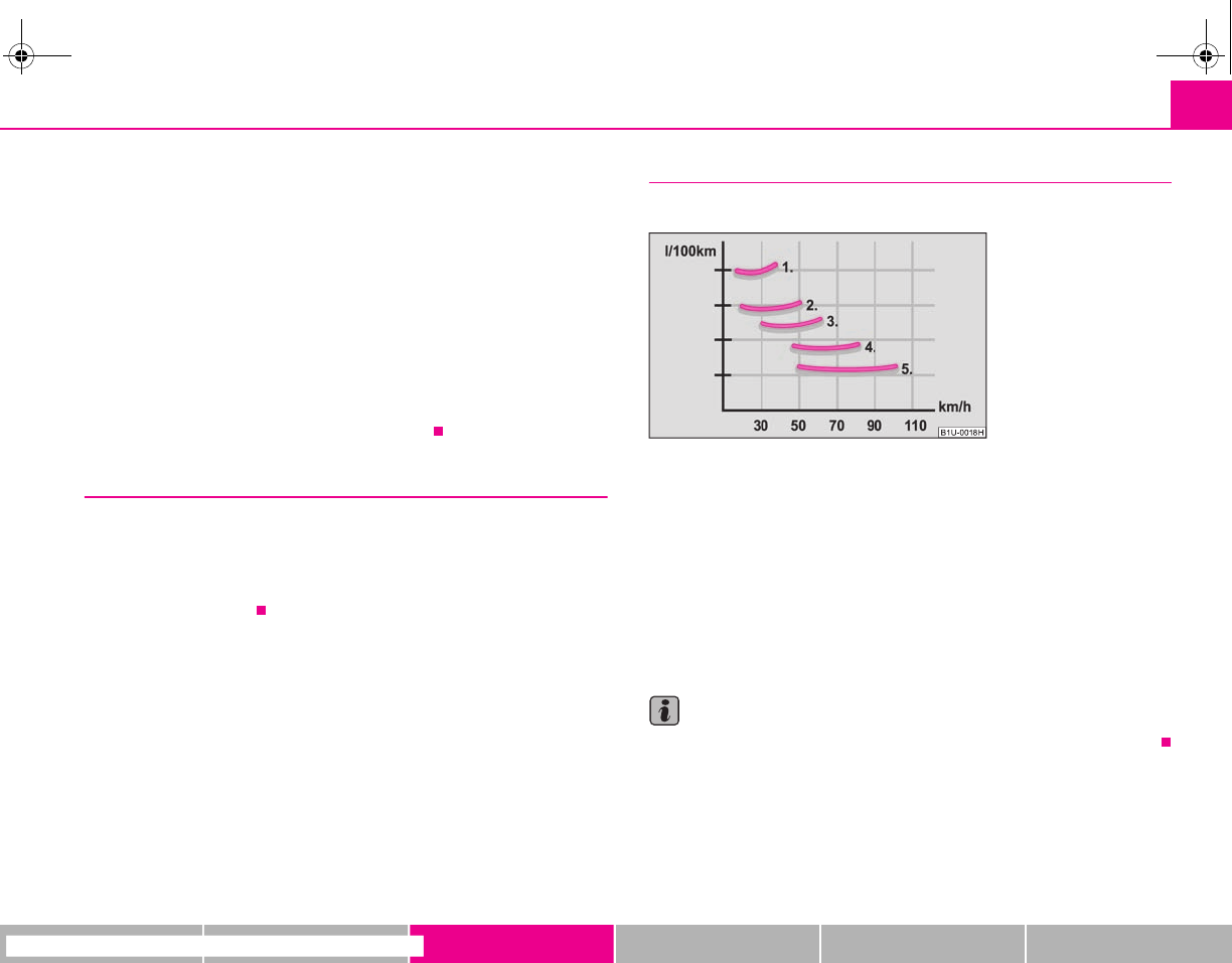
Driving and the Environment 139
riving Tips General Maintenance Breakdown assistance Technical Data
number of tips on how to protect the environment and at the same time save
money.
The fuel consumption can naturally also be influenced by factors which are beyond
the driver's control. It is, for example, normal for the fuel consumption to increase
in winter and under worsened conditions such as poor road conditions, towing a
trailer, etc.
The technical requirements for low fuel usage and economic efficiency of the
vehicle have already been built into the vehicle at the works. Special attention has
been given to minimising negative effects on the environment. It is necessary to
take note of the guidelines given in this chapter in order to make best use of these
characteristics and to maintain their effectiveness.
The optimal engine speed should be obtained when accelerating, in order to avoid
a high fuel consumption and resonance of the vehicle.
Looking ahead when driving
A vehicle's highest fuel consumption occurs it accelerates.
Avoid accelerating and braking unnecessarily. If you drive with forsight you will not
need to brake so often and will also then not have to accelerate so much. Let your
vehicle coast to a stop, for example, if this is possible, when you see that the next
set of traffic lights is at red.
Shifting gears and saving energy
Shifting up early saves on fuel.
Manual gearbox
– Drive no more than about one length of your vehicle in first gear.
– Always shift up into the next higher gear at approx. 2 000 to 2 500 revs.
An effective way of achieving good fuel economy is to shift up early. You will
consume more fuel if you drive at unnecessarily high revolutions in any given gear.
The ⇒fig. 141 shows the ratio of fuel consumption to the speed of your vehicle in
the relevant gears. Fuel consumption in 1st gear is the highest and in 5th gear is the
lowest.
Note
Also use the information supplied by the multi-functional indicator* ⇒page 19.
Fig. 141 Fuel consumption
in litres/100 km. and speed in
km/h.
s2g8.b.book Page 139 Tuesday, April 7, 2009 8:53 AM
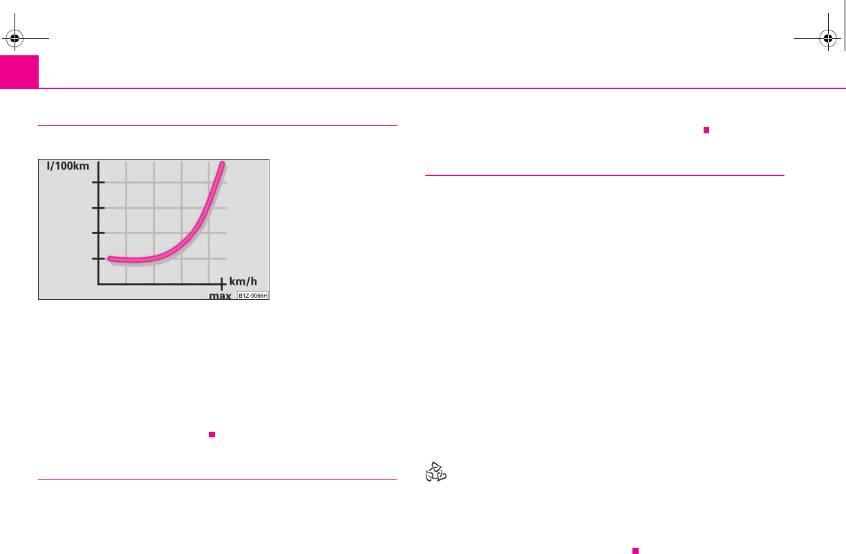
Driving and the Environment140
Avoiding full throttle
Driving more slowly means saving fuel.
Sensitive use of the accelerator will not only significantly reduce fuel consumption
but also positively influence environmental pollution and wear of your vehicle.
You should avoid exploiting the top speed of your vehicle wherever possible. Fuel
consumption, pollutant emissions and vehicle noises increase disproportionally at
high speeds.
The ⇒fig. 142 shows the ratio of fuel consumption to the speed of your vehicle.
You will cut your fuel consumption by half if you only make use three-quarters of
the possible top speed of your vehicle.
Reducing idling
Idling also costs fuel.
It is worthwhile switching off the engine in a traffic jam or when waiting at a level
crossing or at traffic lights with a lengthy red phase. Even after just 30 - 40 seconds
you will have saved more fuel than that is needed when you start the engine up
again.
If an engine is only idling it takes much longer for it to reach its normal operating
temperature. Wear-and-tear and pollutant emissions, though, are particularly high
in the warming-up phase. This is why you should drive off right after starting the
engine. Do avoid high engine revolutions at this time, however.
Regular servicing
A poorly tuned engine consumes an unnecessarily high amount of
fuel.
Having your vehicle serviced regularly at a specialist garge enables you to satisfy
one of the requirements for economical motoring even before you set off on your
journey. Keeping your vehicle properly serviced not only has a positive effect on the
safety of your vehicle and maintaining its value, but also saves on fuel.
A poorly tuned engine can result in a fuel consumption which is 10% higher than
normal.
The foreseen maintenance work should be undertaken exactly according to the
Service schedule by a specialist garage.
Also check the oil level after refueling. Oil consumption is dependent to a consid-
erable extent on the load and speed of the engine. Oil consumption could be as
high as 0.5 litres/1 000 km depending on your style of driving.
It is quite normal that a new engine has a higher oil consumption at first, and
reaches its lowest level only after a certain running in time. It is therefore not
possible to correctly assess the oil consumption of a new vehicle until after you
have driven about 5 000 km.
For the sake of the environment
•You can achieve additional improvements in your fuel economy by using high-
lubricity oils.
•Check the ground below your vehicle at regular intervals to detect any leakages
in good time. Please have your vehicle inspected by a specialist garge if you find any
stains caused by oil or other fluids on the floor.
Fig. 142 Fuel consumption
in litres/100 km. and speed in
km/h.
s2g8.b.book Page 140 Tuesday, April 7, 2009 8:53 AM
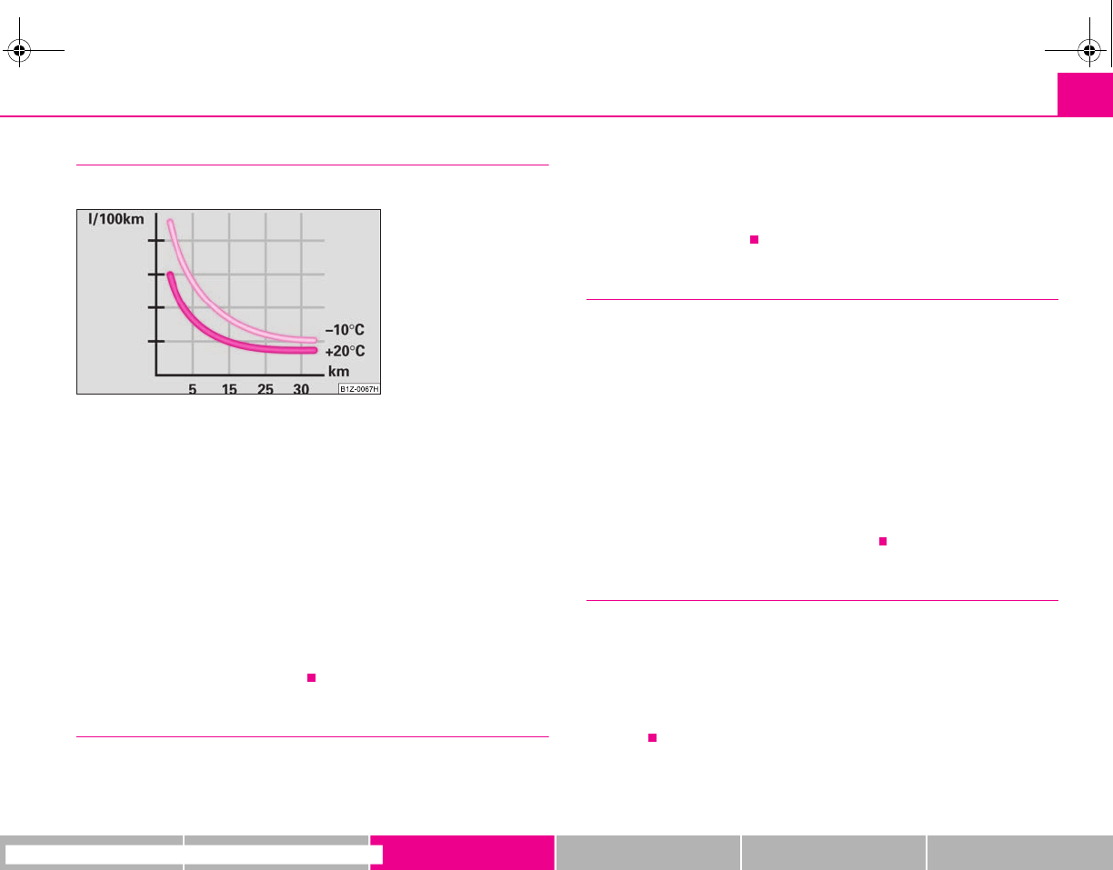
Driving and the Environment 141
riving Tips General Maintenance Breakdown assistance Technical Data
Avoid driving short distances
Short distances result in an above-average high fuel consumption.
– Avoid driving a distance of no more than 4 km if the engine is cold.
The engine and catalytic converter must first have reached their optimal operating
temperature in order to effectively reduce fuel consumption and pollutant emis-
sions.
The cold engine vehicle consumes approx. 15 - 20 litres/100 km of fuel immediately
after starting. Fuel consumption drops to 10 litres/100 km after just 1 kilometre. The
engine reaches its operating temperature (outside temperature and engine
dependent) only after about 4 to 10 kilometres and the fuel consumption then
stabilizes. You should therefore avoid driving short distances whenever possible.
An important factor in this connection is also the ambient temperature. The
⇒fig. 143 shows the different fuel consumptions for the same distance, on the one
hand at +20°C and on the other hand at -10°C. Your vehicle has a higher fuel
consumption in winter than in summer.
Checking tyre inflation pressures
Tyres which are correctly inflated save fuel.
Always ensure that your tyres are inflated to the correct pressure at all times. The
rolling resistance will be increased if the tyre filling pressure is too low. This will not
only increase fuel consumption but also tyre wear and the driving behaviour will
worsen.
Always check the inflation pressure of the tyres when cold.
Do not drive with winter tyres all year round for this costs about 10 % more fuel.
Winter tyres are also louder.
No unnecessary ballast
Transporting ballast costs fuel.
The fact that every kilogram of extra weight increases your fuel consumption
means that it is worth taking a look in the luggage compartment to avoid trans-
porting any unnecessary ballast.
It is particularly in town traffic, when one is accelerating quite often, that the vehicle
weight will have a significant effect upon the fuel consumption. A rule of thumb
here is that an increase in weight of 100 kilograms will cause an increase in fuel
consumption of about 1 litre/100 kilometres.
You may frequently also leave a roof rack fitted on just out of convenience,
although you no longer need it. The increased aerodynamic drag of your vehicle
causes it to use about 10% more fuel than normal at a speed of 100 - 120 km/h,
even when you are not carrying a load on the roof.
Saving electricity
Generating electricity costs fuel.
– Switch off electrical components as soon as you no longer need them.
When the engine is running, the alternator generates and supplies electrical power.
The greater the load on the alternator as a result of having a large number of elec-
trical components switched on, the more fuel will be consumed for operating the
alternator.
Fig. 143 Fuel consumption
in litres/100 km at different
temperatures
s2g8.b.book Page 141 Tuesday, April 7, 2009 8:53 AM

Driving and the Environment142
Keeping a log of your fuel consumption
If you really wish to keep a close check on your fuel consumption, it is best to enter
the figures in a logbook. This does not take much time but is a very worthwhile exer-
cise. It enables you to detect any change (positive and negative) at an early stage
and to take any appropriate action.
If you find that your fuel consumption is too high, you should reflect on how, where
and in what conditions you have driven the vehicle since you last refuelled.
Environmental compatibility
Environmental protection has played a major role in the design, selection of mate-
rials and manufacture of your new Škoda. Particular emphasis has been paid to a
number of aspects, including:
Design measures
•Joints designed to be easily detached;
•Simplified disassembly due to the modular structure system;
•Improved purity of different classes of materials;
•Identification of all plastic parts in accordance with VDA Recommendation 260;
•Reduced fuel consumption and exhaust emission CO2;
•Minimum fuel leakage during accidents;
•Reduced noise.
Choice of materials
•Extensive use of recyclable material;
•Air conditioning filled with CFC-free refrigerant;
•No cadmium;
•No asbestos;
•Reduction in the “vaporisation” of plastics.
Manufacture
•Solvent-free cavity protection;
•Solvent-free protection of the vehicle for transportation from the production
plant to the customer;
•The use of solvent-free adhesives;
•No CFCs used in the production process;
•Without use of mercury;
•Use of water-soluble paints.
Motoring abroad
General
Other circumstances may exist abroad.
It is also possible, in certain countries, that the Škoda Service Partner network is
limited or has not been established yet. This is the reason why obtaining certain
spare parts may be somewhat complicated and specialist garage personnel may
only be able to make limited repairs. Škoda Auto in the Czech Republic and relevant
importers are happy to provide information about technical aspects of the vehicle,
required maintenance work and possibilities for getting repairs done.
Unleaded petrol
A vehicle fitted with a petrol engine must always be refuelled with unleaded petrol
⇒page 138. The automobile associations can provide you with information
regarding the locations of filling stations which offer unleaded petrol.
Headlight
The low beam of your headlights is set asymmetrically. It illuminates the side of the
road on which you are driving to a greater extent. If you drive abroad on the other
side of the road, you will dazzle oncoming traffic.
In order to prevent the dazzling of oncoming traffic, it is necessary to stick a sticker
over a certain part of the headlights.
s2g8.b.book Page 142 Tuesday, April 7, 2009 8:53 AM

Driving and the Environment 143
riving Tips General Maintenance Breakdown assistance Technical Data
Headlight stickers can be obtained as a spare part from the specialist garages.
The adaptation of the headlights with Xenon lamps (applies to vehicles which are
designed for driving on the left and on the right) is performed by switching over a
bezel in the module for low beam by a specialist garage.
Note
You can obtain further information regarding masking over or converting the head-
lights from your specialist garage.
Avoiding damage to your vehicle
When driving on poor roads and lanes or when driving over kerbstones, steep
ramps etc., you must pay particular attention to ensuring that any low-slung parts
of the vehicle, such as spoiler and exhaust, do not touch the ground and get
damaged.
This particularly applies to models with a lowered suspension (sport suspension)
and also when your vehicle is fully laden.
s2g8.b.book Page 143 Tuesday, April 7, 2009 8:53 AM
Towing a trailer144
Towing a trailer
Towing a trailer
Technical requirements
The towing device must satisfy certain technical requirements.
Your vehicle is designed primarily for transporting persons and luggage. It can,
however, also be used for towing a trailer - provided certain technical equipment is
fitted.
If your vehicle has already been supplied with a factory-fitted towing device then
everything that is necessary for towing a trailer in technical terms, and in terms of
the law, has already been taken into account.
Your vehicle is fitted with a 13-pin power socket for the electrical connection
between the vehicle and trailer. If the trailer which you wish to tow has a 7-pin
connector, you can use a suitable adapter 5) from Škoda original accessories.
This work must be carried out in accordance with the manufacturer's specifications
if a towing device is retrofitted.
Specialist garages are familiar with details relating to retrofitting a towing device
and for any necessary modifications to the cooling system.
WARNING
We recommend that you have the towing device from Škoda original acces-
sories installed by a specialist garage. He is familiar with all the relevant
details relating to retrofitting such equipment. There is a risk of an accident
if the towing device is not properly fitted!
General Maintenance
There are a number of points to pay attention to when towing a
trailer.
Trailer load
The permissible trailer load must on no account be exceeded.
You can negotiate appropriately steeper inclines and descents if you do not make
full use of the permissible trailer load.
The trailer loads specified only apply for altitudes up to 1 000 metres above mean
sea level. The fact that the engine power output drops with increasing height due to
a lowering of air pressure and thus the ability to climb, means that the towed weight
must be reduced by 10% for every further increase of 1 000 metres in height above
sea level. The towed weight is the weight of the (laden) vehicle and the (laden)
trailer together. One should take this into account before driving up to higher alti-
tudes.
The trailer and drawbar load information on the type plate of the towing
device are merely test data for the towing device The data relating to your
vehicle, which is often less than this test data, can be found in your vehicle
registration documents.
Distribution of the load
Distribute the load in the trailer in such a way that any heavy items are located as
close as possible to the axle. Secure the items to prevent them slipping.
Tyre inflation pressure
Select the tyre inflation pressure on your vehicle for that of “fully laden”,
⇒page 173. The inflation pressure of the tyres fitted to the trailer adjust in accord-
ance with the manufacturer's recommendation.
Exterior mirrors
You have to have additional exterior mirrors fitted if you are not able to see the
traffic behind the trailer with the standard rear-view mirrors. Both exterior mirrors
5) In some countries the adapter is supplied with the towing device.
s2g8.b.book Page 144 Tuesday, April 7, 2009 8:53 AM

Towing a trailer 145
riving Tips General Maintenance Breakdown assistance Technical Data
should be attached to folding arms. Adjust the mirrors so that they provide you with
an adequate field of view to the rear.
Headlights
Before starting off with a hitched trailer, also check the setting of the headlights.
Alter the setting as necessary with the aid of the headlight beam adjuster
⇒page 51.
Detachable ball head
The ball rod is detachable on vehicles which feature a factory-fitted towing device.
It is stowed together with separate fitting instructions in the spare wheel well in the
luggage compartment of the vehicle.
Further information on the towing device ⇒page 146.
Note
•We recommend that you also have your vehicle inspected between service
intervals if you tow a trailer frequently.
•The handbrake on the towing vehicle must be put on when coupling and
decoupling the trailer.
Driving Tips
Particular caution is required when towing a trailer.
– Do not, as far as possible, drive with your vehicle unladen and the
trailer laden.
– Do not make full use of the legal maximum speeds. This applies in
particular to downhill sections.
– Apply the brakes in good time.
– Keep a check on the coolant temperature gauge if the outside temper-
ature is high.
Distribution of weight
The distribution of the weight is very poor if your vehicle is unladen and the trailer
is laden. Maintain a particularly low speed if you cannot avoid driving with this
combination.
Driving speed
Do not drive faster than 80 km/hour for safety reasons. This also applies for coun-
tries in which higher speeds are allowed.
The fact that the driving stability of the vehicle + trailer combination reduces with
increasing speed means that the legally allowed speed should not be used when
there are unfavourable road, weather or wind conditions, particularly near accident
black spots.
You must always reduce your speed immediately as soon as you detect even just
the slightest swaying of the trailer. On no account attempt to stop the trailer from
“swaying” by accelerating.
Apply the brakes in good time! If the trailer is fitted with a trailer brake, apply the
brakes gently at first and then brake firmly. This will avoid brake jolts resulting from
the trailer wheels locking. Shift down gears in good time before negotiating a down-
hill section to allow the engine to also act as a brake.
Engine overheating
Please keep a check on the coolant temperature gauge if you have to negotiate a
lengthy slope in a low gear at a high engine speed when the outside temperature is
very high ⇒page 16.
If the needle of the coolant temperature gauge moves into the right-hand area or
even the red area of the scale, reduce your speed immediately. Stop and switch off
the engine if the warning light in the instrument cluster begins flashing. Wait a
few minutes and check the level of coolant in the coolant expansion bottle
⇒page 165, “Inspecting the coolant level”.
Please refer to the following guidelines ⇒page 30, “Coolant temperature/ Coolant
quantity ”.
The coolant temperature can be reduced by switching on the heating.
Any increase in the cooling effect of the coolant fan through shifting down a gear
and increasing the engine speed is not possible since the fan speed is independent
s2g8.b.book Page 145 Tuesday, April 7, 2009 8:53 AM
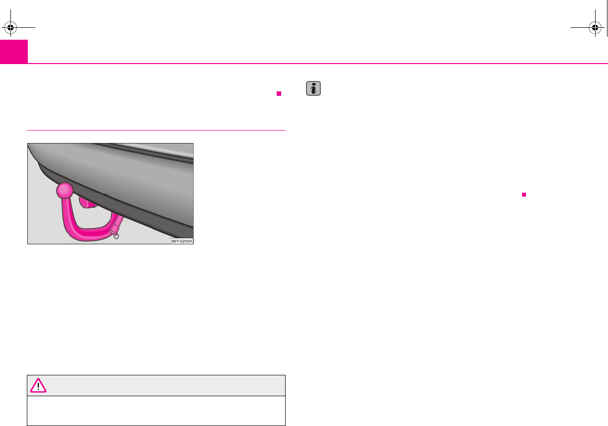
Towing a trailer146
of the engine speed. One should also not drop a gear for this reason when towing
a trailer as long as the engine can manage the slope without any drop in speed.
Detachable towing device*
The detachable ball head of the towing device is stowed in a box for the car tool kit
in the spare wheel well in the luggage compartment.
An instruction for correct installation and removal of the ball head of the towing
device is supplied with the ball head
Inspect the ball head to ensure that it is properly locked each time before setting off.
The inspection is performed by turning the closed locking lever downwards. If the
locking lever can only be turned around a small angle (approx. 5°), the locking
mechanism is O.K. After the inspection pull the locking lever back again to its stop.
The towing device must not be used, if it does not wish to close or the locking lever
turns slightly in the closed position.
WARNING
Do not use any aids or tools for installing or removing the ball head. This
might result in damage to the locking mechanism to the extent that the
safety of the towing device is no longer assured - risk of an accident.
Note
•Do not carry out any modifications or repairs to the ball head or to any other
components on the towing device.
•Contact a specialist garage if you encounter any problems using the device.
•Never unlock the ball head with a trailer coupled to it.
•You should take off the ball head if you drive without towing a trailer. Inspect
whether the end cover properly seals off the mounting shaft.
•Remove the ball head beforehand if you wish to clean your vehicle using a
steam jet. Ensure that the end cover properly seals the mounting shaft.
•It is recommended to wear gloves when installing and removing.
Fig. 144 Detachable ball
head
s2g8.b.book Page 146 Tuesday, April 7, 2009 8:53 AM
Taking care of your vehicle and cleaning the vehicle 147
riving Tips General Maintenance Breakdown assistance Technical Data
General Maintenance
Taking care of your vehicle and cleaning the vehicle
General
Proper care retains the value of your vehicle.
Regular and proper care retains the value of your vehicle. It may also be one of the
requirements for the acceptance of warranty claims relating to corrosion damage
and paint defects on the bodywork.
We recommend using a preservative from Škoda genuine accessories offered by
your Škoda dealer. Please follow the instructions for use on the package.
WARNING
•Care products may be harmful to your health if not used according to the
instructions.
•Always store care products in a safe place, out of the reach of children -
risk of poisoning!
For the sake of the environment
•Always select environmentally-friendly products when purchasing vehicle care
products.
•Do not dispose of the packages with residues of care products in domestic
waste.
Care of the exterior of vehicle
Washing the vehicle
Frequent washing protects your vehicle.
The best protection for your vehicle against harmful environmental influences is
frequent washing and wax treatment. How often you should wash your vehicle
depends on a wide range of factors, such as:
•Frequency of use,
•The parking situation (garage, below trees etc.),
•Season of the year,
•Weather conditions,
•Environmental influences.
The longer insect residues, bird droppings, tree sap, road and industrial dust, tar,
soot particles, road salt and other aggressive deposits remain adhering to the paint-
work of your vehicle, the more detrimental their destructive effect can be. High
temperatures, such as those caused by intensive sun's rays, accentuate this caustic
effect.
It may therefore be necessary, in certain circumstances, to wash the car once a
week. It may also be sufficient, however, to wash the car once a month followed
by appropriate wax treatment.
It is essential to also thoroughly wash the underside of your vehicle at the end of
the winter road salting and gritting period.
WARNING
When washing your vehicle in the winter: Water and ice in the brake system
can affect the braking efficiency - risk of accident!
s2g8.b.book Page 147 Tuesday, April 7, 2009 8:53 AM
Taking care of your vehicle and cleaning the vehicle148
Automatic vehicle wash systems
The paintwork of the vehicle is sufficiently resistant that the vehicle can be washed
normally in automatic vehicle wash plants without any problem. The actual stress
to which the paintwork is subjected, however, depends greatly on the design of the
vehicle wash system, the filtering of the water and the type of washing and care
products used. If the paintwork of your vehicle appears mat after being washed or
even has scratches, point this out to the operator of the vehicle wash plant. Use a
different vehicle wash plant, if necessary.
There are no particular points to note before washing your vehicle in such a plant
other than the usual precautionary measures (closing windows and sliding/tilting
roof, moving any factory-fitted aerials down flat against the bodywork, etc.).
If you have any particular attached parts fitted to your car - such as spoiler, roof rack
system, two-way radio aerial - it is best to first of all consult the operator of the car
wash plant.
It is important to degrease the lips of the windscreen wiper rubbers after passing
through the automatic vehicle wash system.
Caution
Do not screw the swivelling down roof aerial tight before washing the vehicle in an
automatic vehicle wash system - risk of damage!
Washing vehicle by hand
It is important to first soften the dirt with plenty of water and rinse it off as thor-
oughly as possible before washing your vehicle by hand.
One should then clean the vehicle using a soft washing sponge, washing glove or
a washing brush and only slight pressure. Work from the top to the bottom -
beginning with the roof. Only place slight pressure on the vehicle paintwork during
cleaning Only use a car shampoo for stubborn dirt.
Wash out the sponge or washing glove thoroughly at short intervals.
Clean wheels, door sills and similar parts last. Use a second sponge for such areas.
Rinse off the vehicle well after giving it a wash and dry it off using a chamois leather.
WARNING
•The ignition should always be switched off when you wash your vehicle -
risk of accident!
•Protect your hands and arms from sharp-edged metal parts when you
are cleaning the underfloor, the inside of the wheel housings or the wheel
trims - risk of cuts.
Caution
•Do not wash your vehicle in bright sunlight - risk of paint damage.
•Ensure that the jet of water is not aimed directly at the locking cylinders or at the
door and panel joints if you spray your vehicle in winter down with a hose - risk of
freezing.
•Do not use any insect sponges, rough kitchen sponges or similar cleaning prod-
ucts - risk of damage to the surface of paintwork.
For the sake of the environment
Only wash your vehicle at washing bays specifically reserved for this purpose. This
ensures that no water which may be contaminated by oil flows into the sewage
system. It is not even permitted to wash your vehicle in certain areas except at such
specific washing bays.
Washing with a high-pressure cleaner
When you wash your vehicle with a high-pressure cleaner, it is essential to comply
with the instructions for use of the cleaning equipment. This applies in particular to
the pressure used and to the spraying distance. Maintain a sufficiently large
distance to soft materials such as rubber hoses or insulation material.
On no account use circular spray nozzles or so-called dirt cutters!
s2g8.b.book Page 148 Tuesday, April 7, 2009 8:53 AM
Taking care of your vehicle and cleaning the vehicle 149
riving Tips General Maintenance Breakdown assistance Technical Data
WARNING
It is particularly important that you do not clean tyres with circular spray
jets. Visible but also invisible damage to tyres may occur even at a relatively
large spraying distance and if sprayed only for a short time - risk of accident!
Caution
The water containing wax must be no hotter than 60°C, otherwise the vehicle can
be damaged.
Wax treatment
Good wax treatment is an effective way of protecting the paintwork from harmful
environmental influences and minor mechanical damage.
The vehicle must be treated with a high-quality hard wax polish at the latest, when
no more drops form on the clean paintwork.
A new layer of a high-quality hard wax polish can be applied to the clean bodywork
after it has dried thoroughly. Even if you use a wax preserver regularly we still
recommend that you treat the paintwork of the vehicle at least twice a year with
hard wax.
Caution
Never apply wax to the windows.
Polishing
Polishing is only necessary if the paintwork of your vehicle has become unattractive
and if it is no longer possible to achieve a gloss with wax preservers.
You must treat the paintwork with a wax preserver if the polish you use does not
contain any preserving elements ⇒page 149, “Wax treatment”.
We recommend using a preservative from Škoda genuine accessories offered by
your Škoda dealer.
Caution
•You must not treat mat painted parts or plastic with polishing products or hard
wax.
•Do not polish the paintwork of the vehicle in a dusty environment, otherwise
the paintwork can be scratched.
Chrome parts
First clean the chrome parts with a damp clotch and then polish them with a soft,
dry cloth. If it does not prove to be adequate, use a chrome care product from
Škoda original accessories.
Caution
Do not polish the chrome parts in a dusty environment, otherwise they can be
scratched.
Paint damage
Slight damage to paintwork such as scratches, scuffs or traces of chip damage must
be touched up immediately with paint (Škoda painting pen) before any corrosion
can result. You can of course have this work carried out by a specialist garage.
Specialist garages have a range of matching touch-up pens or spray cans available
in the colour of your vehicle.
The paint number of the original paintwork of your vehicle is indicated on the
vehicle data sticker ⇒page 201.
Any corrosion which has already have formed must be removed thoroughly. Apply
a corrosion protection primer and then the paint to the affected point. You can of
course have this work carried out by a specialist garage.
s2g8.b.book Page 149 Tuesday, April 7, 2009 8:53 AM
Taking care of your vehicle and cleaning the vehicle150
Plastic parts
External plastic parts are cleaned by normal washing. Plastic parts and synthetic
leather can also be treated with special solvent-free plastic cleaning agents if a
damp cloth is not sufficient. Paint care products are not suitable for plastic parts.
Caution
Solvent-free cleaners attack the material and can damage it.
Windows
Only use a plastic ice scraper for removing snow and ice from the windows and
mirrors. You should not move the ice scraper forward and backward but in one
direction on the window which you are cleaning in order to avoid any damage to
the surface of the glass.
You can best remove residues of rubber, oil, grease, wax or silicone by using a
special window cleaner or a special silicone remover.
You should also clean the windows regularly from the inside.
Do not use window leathers which you have used to polish the vehicle body to dry
off the windows. Residues of preservatives in the window leather can dirty the
window and reduce visibility.
Do not affix any stickers over the inside of the rear window to avoid damage to the
heating elements of the rear window heater.
We recommend using a preservative from Škoda genuine accessories offered by
your Škoda dealer.
Caution
Never remove snow or ice from the glass parts with warm or hot water - risk of
formation of cracks in the glass!
The headlight lenses
Please do not use any aggressive cleaning or chemical solvent products for cleaning
the front headlights - risk of damage to the plastic lenses. Please use soap and
clean warm water.
Caution
Never wipe the headlights dry and do not use any sharp objects for cleaning the
plastic lenses, this may result in damage to the protective paintwork and conse-
quently in formation of cracks on the headlight lenses, e.g through effect of chem-
ical products.
Door and window seals
The rubber seals on the doors, boot lid, bonnet and windows remain supple and
last longer if you treat them from time to time with a rubber care product (e.g. with
a spray with silicone-free oil). You also avoid premature wear of the seals and
prevent leakages in this way. It is also easier to open the doors. Rubber seals which
are well cared for also do not stick together in cold winter weather.
Locking cylinder
We recommend that you use the spray from Škoda original accessories with
regreasing and anticorrosive effect for de-icing locking cylinders.
Note
When washing your vehicle, ensure that as little water as possible gets into the
locking cylinders.
s2g8.b.book Page 150 Tuesday, April 7, 2009 8:53 AM
Taking care of your vehicle and cleaning the vehicle 151
riving Tips General Maintenance Breakdown assistance Technical Data
Wheels
Steel wheels
You should also thoroughly wash the wheels and wheel trims when giving your
vehicle its regular wash. This prevents any brake dust, dirt and road salt from
sticking to the wheel hubs. You can remove stubborn brake abrasion adhering to
the wheels with an industrial cleaner. Touch up any damage to the paintwork on the
wheels before rust is able to form.
Light alloy wheels
Regular care of light alloy wheels is necessary in order to retain their decorative
appearance over long periods. It is particularly useful to remove any road salt and
brake abrasion from the light alloy wheels every two weeks, otherwise the paint-
work of the wheel rim will suffer damage. Wash thoroughly and then treat the
wheels with a protective product for light alloy wheels which does not contain any
acidic components. You should provide the wheel hubs with a hard wax layer every
three months. You must not use any products which cause abrasion when treating
the wheel hubs. Any damage to the paint layer on the wheel hubs must be touched
up immediately.
We recommend using a preservative from Škoda genuine accessories offered by
your Škoda dealer.
WARNING
One should remember when cleaning the wheels that moisture, ice and road
salt may adversely affect braking efficiency - risk of an accident!
Note
Severe layers of dirt on the wheels can also result in wheel imbalance. This may
show itself in the form of a wheel vibration which is transmitted to the steering
wheel which, in certain circumstances, can cause premature wear of the steering.
This means it is necessary to remove the dirt.
Underbody protection
The underside of your vehicle is protected for life against chemical and mechanical
influences.
One cannot, however, completely rule out damage to the protective layer when
driving so we recommend that you inspect the protective layer on the underside of
your vehicle and on the chassis at certain intervals - this is best done at the begin-
ning and end of the winter - and to touch up any damaged areas.
Specialist garages have suitable spray products available as well as the necessary
equipment and are familiar with the instructions for use. It is therefore best to have
such touch-up work or additional corrosion protection measures carried out by a
specialist garage.
WARNING
Never use additional underbody protection or corrosion-protection agents
for the exhaust pipes, catalytic converters, diesel particle filter or heat
shields. When the engine reaches its operating temperature, these
substances might ignite - risk of fire!
Protection of hollow spaces
All the cavities of your vehicle which are at risk from corrosion are protected for life
by a layer of protective wax applied in the factory.
This wax protection does not require to be inspected or re-treated. Please remove
any small amount of wax which flows out of the cavities at high temperatures with
a plastic scraper and clean the spot using petroleum cleaner.
WARNING
Safety and environmental protection regulations should observed when
using petroleum cleaner to remove wax - a risk of fire!
s2g8.b.book Page 151 Tuesday, April 7, 2009 8:53 AM
Taking care of your vehicle and cleaning the vehicle152
Engine compartment
Good corrosion protection is very important, particularly in winter when one often
drives over its salt-strewn roads. One should therefore clean the whole engine
compartment before and after the salt spreading period and treat with preservative
in order to prevent the salt from being destructive.
Specialist garages have the cleaning agents and preservatives recommended by the
manufacturer and also the required equipment.
WARNING
•It is necessary to observe the guidelines given in the chapter before
working on the engine compartment ⇒page 160.
•Let the engine cool down before cleaning the engine compartment.
Caution
•Engine cleaning may be only be undertaken when the ignition is off.
•It is recommended to cover the generator before washing the engine compart-
ment.
For the sake of the environment
The dirty water produced by washing the engine has washed away petrol, and resi-
dues of grease and oil and should therefore be cleaned by an oil separator. This is
why engine washing should only be undertaken in a specialist garage or at a fueling
station (when these are fitted with the required equipment).
Care of the interior of vehicle
Plastic parts, artificial leather and cloths
You can clean plastic parts and artificial leather with a moist cloth. You should only
treat such parts with special solvent-free plastic cleaning and care products it
does prove to be adequate.
Upholstery cloth and cloth trim on the doors, luggage compartment cover, head-
liner etc. are best treated with special cleaning products, using if necessary a dry
foam and a soft sponge or brush.
We recommend using a cleaning product from Škoda genuine accessories offered
by your Škoda dealer.
Caution
Solvent-free cleaners attack the material and can damage it.
Fabric covers of electrically heated seats
Do not clean the seat covers moist as this may result in damage to the seat heating
system.
Clean such covers using special agents, for example dry foam.
Natural leather
Natural leather requires quite particular care and attention.
Leather should be treated from time to time according the following
guidelines depending on how much it is used.
Normal cleaning
– Clean soiled areas of the leather with slightly moistened cotton or
woollen cloth.
Severe soiling
– Clean severely soiled areas with a cloth dipped in a mild soapy solu-
tion (2 spoonfuls of natural soap to 1 litre of water).
– Ensure that the leather is not soaked through at any point and that no
water gets into the stitching of the seams.
– Dry off the leather with a soft, dry cloth.
s2g8.b.book Page 152 Tuesday, April 7, 2009 8:53 AM
Taking care of your vehicle and cleaning the vehicle 153
riving Tips General Maintenance Breakdown assistance Technical Data
Removing stains
– Remove fresh stains which are water-based (e.g. coffee, tea, juices,
blood etc.) with an absorbent cloth or household paper or use the
cleaner from the care set for a stain which has already dried in.
– Remove fresh stains on a fat base (e.g. butter, mayonnaise, chocolate
etc.) with an absorbent cloth or household cleaning paper or with the
cleaner from the care set if the stain has not yet penetrated into the
surface.
– Use a grease dissolver for grease stains which have dried in.
–Eliminate special stains (e.g. ball-point pens, felt pen, nail varnish,
dispersion paint, shoe cream etc.) with a special stain remover suit-
able for leather.
Leather care
– Treat the leather every six months with the leather care product avail-
able from specialist garages.
– Apply only a small amount of the care product.
– Dry the leather off with a soft cloth
We recommend that you consult a specialist garage if you have any questions
regarding cleaning and care of the leather interior in your vehicle.
Caution
•You must on no account treat the leather with solvents (e.g. gasoline, turpen-
tine), floor wax, shoe cream or such like.
•Avoid leaving your vehicle for lengthy periods in bright sunlight in order to
avoid bleaching the leather. If you leave your vehicle parked in the open for lengthy
periods, protect the leather from the direct rays of the sun by covering it over.
•Sharp-edged objects on items of clothing such as zip fasteners, rivets, sharp-
edged belts may leave permanent scratches or signs of rubbing on the surface.
Note
•Use a care cream with light blocker and impregnation effect regularly and each
time after cleaning the leather. The cream nourishes the leather, allows it to breathe
and keeps it supple and also provides moisture. It also creates surface protection.
•Clean the leather every 2 to 3 months, remove fresh soiling each time this
occurs.
•Remove fresh stains such as those from ball-point pens, ink, lipstick, shoe
cream etc., as quickly as possible.
•Care also for the leather dye. Refreshen areas which have lost their colour with
a special coloured leather cream as required.
•The leather is a natural material with specific properties. During the use of the
vehicle, minor optical changes can occur on the leather parts of the covers (e. g
wrinkles or creases as a result of the stress of the covers).
Seat belts
– Keep the seat belts clean!
– Wash seat belts which have become soiled using a mild soapy solu-
tion.
– Inspect the seat belts regularly to ensure they are in good condition.
Belt webbing which has become severely soiled may prevent the inertia reel from
reeling up the belt properly.
WARNING
•The seat belts must not be removed for cleaning.
•Never clean the seat belts chemically as dry cleaning may destroy the
fabric. The seat belts must also not be allowed to come into contact with
corrosive liquids (such as acids etc.).
•Seat belts which have damage to the webbing, the connections, the
inertia reel or the lock should be replaced by a specialist garage.
s2g8.b.book Page 153 Tuesday, April 7, 2009 8:53 AM
Taking care of your vehicle and cleaning the vehicle154
•Inertia reel belts must be completely dried before being reeled up.
WARNING (continued)
s2g8.b.book Page 154 Tuesday, April 7, 2009 8:53 AM
Fuel 155
riving Tips General Maintenance Breakdown assistance Technical Data
Fuel
Petrol
Grades of petrol
There are various grades of petrol. Please check in order to know which grade of
petrol your vehicle requires. You will also find the same information affixed to the
inside of the fuel filler flap of your vehicle ⇒page 156.
A distinction is made between unleaded and leaded petrol. All Škoda vehicles with
petrol engines are equipped with a catalytic converter and must therefore be only
driven with unleaded petrol. Unleaded petrol complies with the standard EN 228.
The individual grades of petrol are distinguished by their octane number (RON).
Please adopt the following procedure if the grade of petrol which you normally use
is not be available in exceptional circumstances:
•Engines which need unleaded premium petrol 95 RON can also be run on
unleaded regular petrol 91 RON. This does, however, result in a slight loss in
performance.
•Engines which need unleaded premium plus 98 RON can also be run on
unleaded premium petrol 95 RON. This could result in a slight loss in engine
performance. You can in case of need also use unleaded regular petrol 91 RON in
the event that neither unleaded premium plus 98 RON nor unleaded premium
petrol 95 RON is available. Refuel as soon as possible with unleaded premium plus
98 RON or unleaded premium petrol 95 RON.
If, in an emergency, the only fuel available is one which has a lower octane number
than that required by the engine then only drive at medium engine speeds and
lower engine loadings.
You can make unlimited use of fuel which has a higher octane number than that
required by the engine. There will, however, be no advantages gained by this in
terms of engine performance and fuel consumption!
The handling, performance and life of your engine are determined to a significant
extent by the quality of the fuel. Do not use any petrol additives. Use a fuel
complying with the standard.
You can find further information on refuelling ⇒page 156, “Refuelling”.
Caution
•Filling the tank even only once with leaded petrol will result in the catalytic
converter being destroyed.
•Operating the engine with petrol of a low octane number can result in engine
damage at high revolutions or severe engine loading.
Diesel
Diesel fuel
Your vehicle can be operated with diesel fuel, which complies with the standard
EN 590.
Fuel additives
You must not use fuel additives, so-called “flow improvers” (petrol and similar
products) in diesel fuel.
If the quality of the diesel fuel is poor, it is then necessary to drain the fuel filter
more often than stated in the Service schedule.
You can find information on refuelling ⇒page 156, “Refuelling”.
Caution
•Use fuel which complies with the standard DIN EN 590. Filling the tank even
only once, which does not comply with the standard, can result in damage to the
fuel system.
•Water which has collected in the fuel filter can result in engine problems.
•Your vehicle is not adapted for use of biofuel (RME), therefore this fuel must not
be refuelled and driven. Using this fuel (RME) can lead to damage to the engine or
the fuel system.
s2g8.b.book Page 155 Tuesday, April 7, 2009 8:53 AM
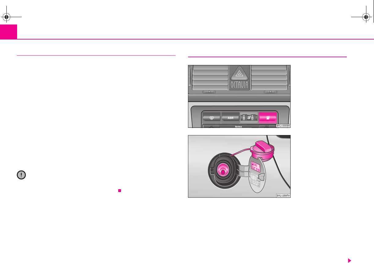
Fuel156
Operation in winter
Winter-grade diesel fuel
A different grade of diesel fuel is available at filling stations in winter than during the
summer. Using “summer-grade diesel fuel” at temperatures below 0°C can result in
operational problems because the diesel becomes viscous as a result of paraffin
separation.
It is therefore the case that EN 590 prescribes diesel fuel class for certain periods of
the year which can also be purchased at the corresponding time during the year.
“Winter-grade diesel fuel” will still operate properly even at a temperature of -20°C.
It is often the case in countries with different climatic conditions that diesel fuels
available have a different temperature characteristic. The specialist garages and the
filling stations in the country concerned will be able to provide you with informa-
tion regarding the diesel fuels available.
Prewarming fuel
The vehicle is fitted with a fuel filter prewarming system. This secures operation of
a vehicle using diesel fuel down to an environmental temperature of -25°C.
Caution
It is not permitted to add the various fuel additives on the market, including petrol,
to diesel fuel in order to improve its flow properties.
Refuelling
The filler tube of the fuel reservoir is located in the rear right side part of
the vehicle.
Opening the fuel filler cap
– Open the fuel filler flap with the hand.
– On vehicles without remote unlocking of the fuel filler flap from the
driver's seat, unlock the fuel filler cap on the fuel filler tube by turning
the vehicle key to the left.
Fig. 145 Switch for opening
the fuel filler flap from the
driver seat
Fig. 146 Fuel filler flap with
cap unscrewed
s2g8.b.book Page 156 Tuesday, April 7, 2009 8:53 AM
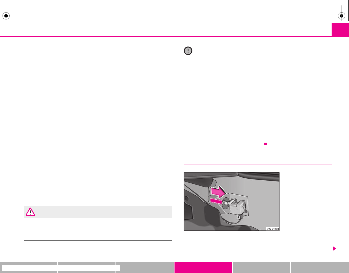
Fuel 157
riving Tips General Maintenance Breakdown assistance Technical Data
– Unscrew the fuel filler cap anti-clockwise and place the fuel filler cap
from above on the fuel filler flap ⇒page 156, fig. 146.
Closing fuel filler cap
– Screw on the cap by turning it to the right until it is heard to lock.
– On vehicles without remote unlocking of the fuel filler flap from the
driver's seat, lock the fuel filler cap on the fuel filler tube by turning the
vehicle key to the right and withdraw the key.
– Close the fuel filler flap until it locks.
Open the fuel filler flap from the driver's seat*
– Press the switch to open the fuel filler flap ⇒page 156, fig. 145.
– Unscrew the fuel filler cap anti-clockwise and place the fuel filler cap
from above on the fuel filler flap ⇒page 156, fig. 146.
Closing fuel filler cap
– Screw on the cap by turning it to the right until it is heard to lock.
– Close the fuel filler flap until it locks.
The correct grade of fuel for your vehicle as well as the tyre size and inflation pres-
sures are stated on a sticker affixed to the inside of the fuel filler flap. Further infor-
mation on fuel ⇒page 155, “Fuel”.
The fuel tank has a capacity of about 55 litres.
WARNING
Pay attention to any legal requirements if you do carry a spare canister in the
vehicle. We do not recommend carrying any fuel canisters in your vehicle for
safety reasons. The canister can be damaged in the event of an accident and
fuel may leak out.
Caution
•Before refuelling it is necessary to switch off the auxiliary heating system (auxil-
iary heating and ventilation) *.
•Remove any fuel which has spilled onto the paintwork of your vehicle immedi-
ately - risk of paint damage!
•On vehicles fitted with a catalytic converter, never let the fuel tank run
completely empty. An irregular supply of fuel to the engine can result in misfiring
and unburnt fuel may get into the exhaust system, which may result in overheating
and damage to the catalytic converter.
•Make sure that the valve is not pressed into the filler tube when inserting the
pump nozzle into the filler tube. Otherwise you are unintentionally filling up the
volume, which in case of heat can cause an expansion of the fuel. This can lead to
an overflow of fuel or damage to parts of the fuel reservoir.
•The fuel tank is full just as soon as the pump nozzle switches off for the first time,
provided the nozzle has been operated properly. Do not continue refuelling -
otherwise the expansion volume is filled up.
Emergency release of fuel filler flap
If a fault exists in the system for opening the fuel filler flap from the
driver's seat*, the fuel filler flap can be opened manually.
Fig. 147 Luggage compart-
ment: Emergency release of
fuel filler flap
s2g8.b.book Page 157 Tuesday, April 7, 2009 8:53 AM
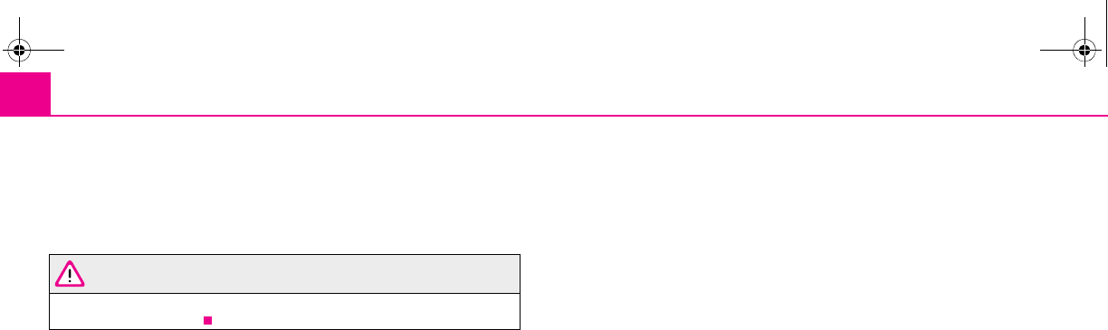
Fuel158
Unlocking
– Open the boot lid and remove the right inner paneling.
– Pull on the control cable in direction of arrow in order to unlock the
fuel filler flap ⇒page 157, fig. 147.
WARNING
When unlocking the fuel filler flap manually, pay attention to sharp edges of
the body - risk of injury.
s2g8.b.book Page 158 Tuesday, April 7, 2009 8:53 AM
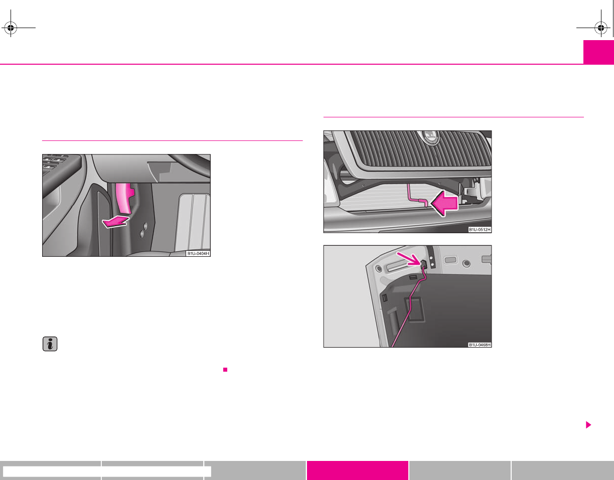
Inspecting and replenishing 159
riving Tips General Maintenance Breakdown assistance Technical Data
Inspecting and replenishing
Engine compartment
Bonnet remote release
Bonnet remote release
– Pull the unlocking lever below the dash panel on the driver's side
⇒fig. 148.
The bonnet jumps out of its lock as a result of the spring force.
Note
Ensure that the windscreen wiper arms are not folded out before opening the
bonnet otherwise damage could occur to the paintwork.
Opening and closing the bonnet.
Opening the bonnet
– Unlock the bonnet ⇒fig. 148.
– Grip with the hand under the radiator grille and lift up the bonnet.
– Press the locking lever in direction of arrow ⇒fig. 149 and lift up the
bonnet.
Fig. 148 Bonnet release
lever
Fig. 149 Radiator grille:
Locking lever
Fig. 150 Securing the bonnet
with the bonnet support
s2g8.b.book Page 159 Tuesday, April 7, 2009 8:53 AM
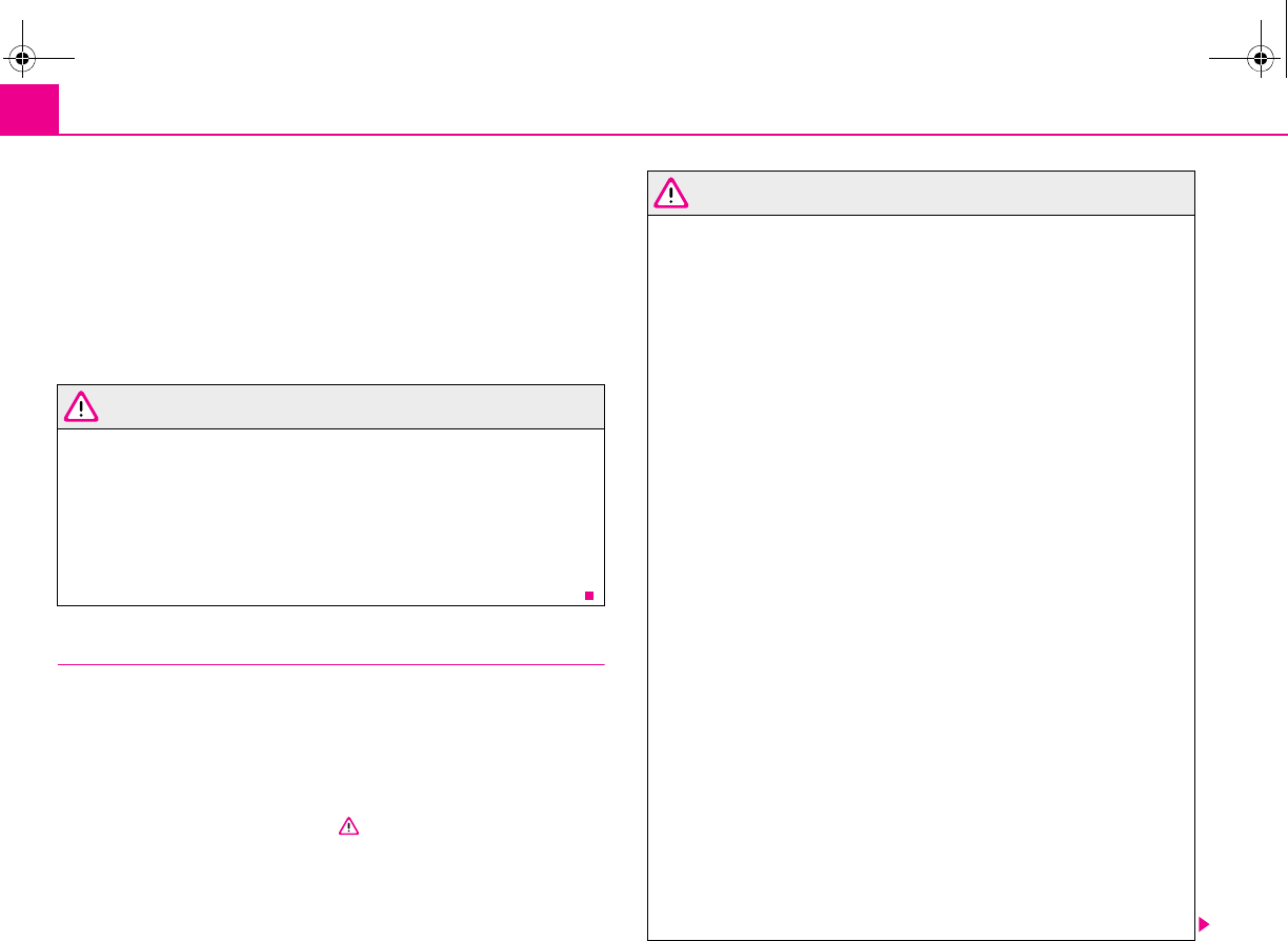
Inspecting and replenishing160
– Take the bonnet support out of its holder and set it in the opening
designed for it ⇒page 159, fig. 150.
Closing the bonnet
– Lift the bonnet slightly and unhook the bonnet support. Press the
bonnet support into the holder designed to hold it.
– Allow the bonnet to drop from a height of about 30 cm into the lock -
bonnet do not press down on it!
WARNING
•Never open the bonnet if you see that steam or coolant is flowing out of
the engine compartment - risk of scalding! Wait long enough until the steam
or coolant has stopped escaping.
•For safety reasons, the bonnet must always be properly closed when
driving. One should therefore check that the lock has in fact engaged prop-
erly after closing the bonnet.
•Stop your vehicle immediately while driving if you notice that the lock is
not properly engaged and close the bonnet properly - risk of an accident!
Working in the engine compartment
Particular care is required when carrying out any work in the engine
compartment!
There is a risk of injuries, scalding, accidents and fire when working in the
engine compartment, e.g. inspecting and replenishing oil and other fluids. For
this reason, it is essential to comply with the warning instructions stated
below and with the general applicable rules of safety. The engine compart-
ment of your car is a hazardous area ⇒.
WARNING
•Never open the bonnet if you see that steam or coolant is flowing out of
the engine compartment - risk of scalding! Wait long enough until the steam
or coolant has stopped escaping.
•Switch off the engine and pull out the ignition key.
•Apply the handbrake firmly.
•On vehicles fitted with a manual gearbox, move the gearshift lever into
Neutral.
•Allow the engine to cool down.
•Keep children clear of the engine compartment.
•Never spill oil and other fluids over the hot engine. Such fluids (e.g. the
antifreeze contained in the coolant) may ignite!
•Avoid short circuits in the electrical system - particularly on the battery.
•Never place your hand into the radiator fan as long as the engine is still
warm. The fan might suddenly start running!
•Never open the cap of the coolant expansion bottle as long as the engine
is still warm. The cooling system is pressurized!
•Cover over the cap of the coolant expansion reservoir with a large cloth
when opening it as protection for your face, hands and arms from hot steam
or hot coolant.
•Do not let objects, such as e.g cleaning cloth or tools lie in the engine
compartment.
•If you wish to work under the vehicle, you must secure the vehicle from
rolling away and support it with suitable supporting blocks; the lifting jack*
is not sufficient for this - risk of injury!
•In cases where it be necessary to carry out inspection work when the
engine is running there is an additional risk from rotating parts (e.g. the V-
ribbed belt, alternator, radiator fan) and from the high-voltage ignition
system. Please observe in addition the following:
−Never touch the electrical cables of the ignition system.
−Absolutely avoid any jewellery, loose items of clothing or long hair
from getting into the rotating parts of the engine - Hazard! Therefore
s2g8.b.book Page 160 Tuesday, April 7, 2009 8:53 AM
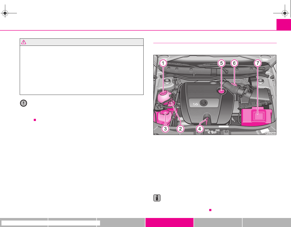
Inspecting and replenishing 161
riving Tips General Maintenance Breakdown assistance Technical Data
remove any jewellery beforehand, tie up your hair and wear tight fitting
clothing.
•Please also comply with the warning instructions stated below when
carrying out any essential work on the fuel system or on the electrical
system:
−Always separate the car battery from the electrical system.
−Do not smoke.
−Never carry out any work close to naked flames.
−Always keep a working fire extinguisher at hand.
Caution
When replenishing fluids in the engine, always ensure that the fluids are on no
account mixed up. This may result in major operating problems and also vehicle
damage!
Overview of the engine compartment
The main inspection points.
Fig. 151 1.6 ltr./75 kW petrol engine
1.6 ltr./75 kW petrol engine ⇒fig. 151
Coolant expansion bottle . . . . . . . . . . . . . . . . . . . . . . . . . . . . . . . . . . .
Reservoir for hydraulic liquid of power steering
Windshield washer fluid reservoir . . . . . . . . . . . . . . . . . . . . . . . . . . .
Engine oil dipstick . . . . . . . . . . . . . . . . . . . . . . . . . . . . . . . . . . . . . . . . . .
Engine oil filler opening . . . . . . . . . . . . . . . . . . . . . . . . . . . . . . . . . . . .
Brake fluid reservoir . . . . . . . . . . . . . . . . . . . . . . . . . . . . . . . . . . . . . . . .
Battery (below a cover) . . . . . . . . . . . . . . . . . . . . . . . . . . . . . . . . . . . . .
Note
The location of the inspection points in the engine compartment of petrol and
diesel engines is practically identical.
WARNING (continued)
A
1165
A
2
A
3172
A
4163
A
5163
A
6167
A
7168
s2g8.b.book Page 161 Tuesday, April 7, 2009 8:53 AM
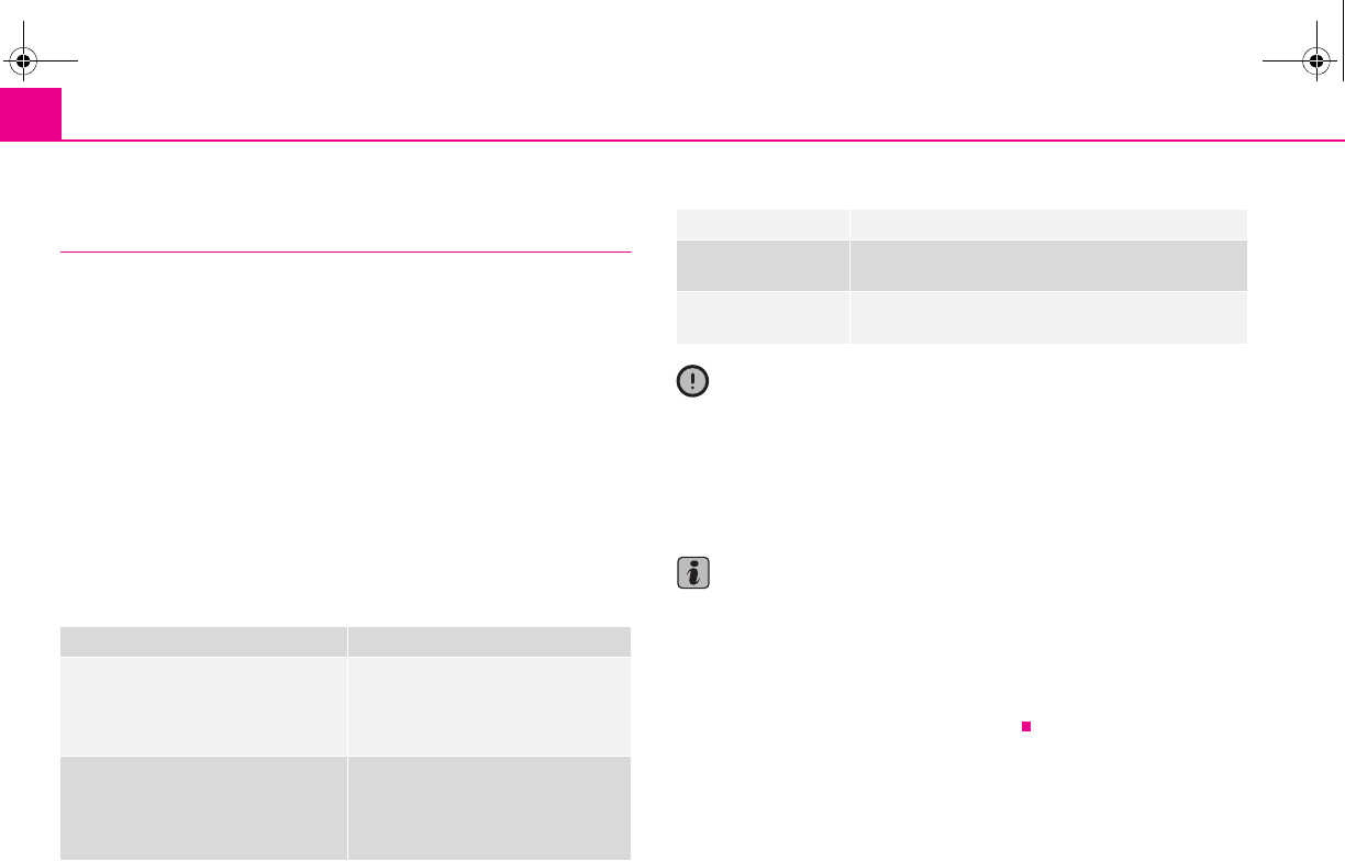
Inspecting and replenishing162
Engine oil
Engine oil specifications
The grade of engine oil should be selected in accordance with
precise specifications.
The engine of your vehicle has been factory-filled with a high-grade oil which you
can use throughout the year - except in extreme climatic regions.
You can mix various oils together with each other when refilling with oil. This does
not, however, apply for models with flexible service intervals (QG1).
Engine oils are, of course, undergoing continuous further development. Thus the
information stated in this Owner's Manual is only correct at the time of publication.
Specialist garages are informed by Škoda Auto about current changes. We recom-
mend having this oil change undertaken by a specialist garage.
The specifications (VW standards) stated in the following must be indicated sepa-
rately or together with other specifications on the bottle.
Engine oil specifications for vehicles with fixed service intervals (QG0, QG2)
Engine oil specifications for models with flexible service intervals (QG1)
Caution
Only the above-mentioned oils may be used on vehicles with flexible service inter-
vals (QG1). We recommend always refilling with oil of the same specification since
this will maintain the properties of the oil. In exceptional cases, you must top up
only once engine oil complying with Specification VW 502 00 (only for petrol
engines) or Specification VW 505 01 (only for diesel engines) to maximum 0.5 litres.
You must not use other engine oils - risk of engine damage!
Note
•Before a long drive we recommend that you purchase and carry with you
engine oil which complies with the specification for your vehicle. Consequently,
you will always have the correct engine oil for refilling.
•We recommend using a preservative from the Škoda original accessories
offered by your Škoda dealer.
•For further information - see Service shedule.
Engine oil specifications
Petrol engines
VW 501 01
VW 502 00
VW 504 00
ACEA A2 a) or A3 a)
a) Only to be used in exceptional cases if the oils specified above are not available.
Diesel engines
VW 505 00b)
VW 505 01
VW 507 00
ACEA B3a) or B4a)
b) Except PD engine (unit injector engine).
Engine oil specifications
Petrol engines VW 503 00
VW 504 00
Diesel engines VW 506 01
VW 507 00
s2g8.b.book Page 162 Tuesday, April 7, 2009 8:53 AM
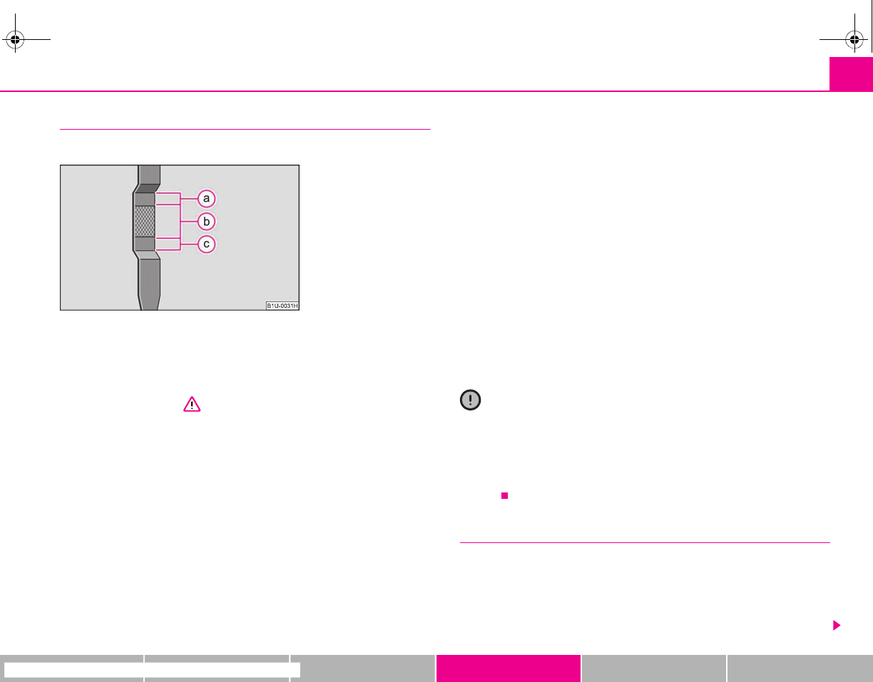
Inspecting and replenishing 163
riving Tips General Maintenance Breakdown assistance Technical Data
Check engine oil level
The dipstick indicates the level of oil in the engine.
Checking the oil level
– Ensure that the vehicle is positioned on a level surface.
– Switch the engine off.
– Open the bonnet ⇒ in “Working in the engine compartment” on
page 160.
– Wait a few minutes and pull out the oil dipstick .
– Wipe off the dipstick with a clean cloth and insert it again fully.
– Then withdraw the dipstick again and read off the oil level.
Oil level within range
– You must not top up the oil.
Oil level within range
– You may top up the oil. It is possible that the oil level may then be
within range after doing this.
Oil level within range
–You must top up the oil ⇒page 163. It is sufficient, once this is done,
to keep the oil level within range .
It is normal for the engine to consume oil. The oil consumption may be as much as
0.5 l/1 000 km depending on your style of driving and the conditions under which
you operate your vehicle. The oil consumption may be slightly higher than this
during the first 5 000 kilometres.
One should therefore check the oil level at regular intervals, preferably every time
after the fuel tank is filled or after driving for long stretches.
We recommend maintaining the oil level within the range if the engine has been
operating at high loads, for example during a lengthy motorway trip during the
summer months, towing a trailer or negotiating a high mountain pass, but not
above this.
The warning light in the instrument cluster will indicate whether the oil level is too
low ⇒page 31. In this case, check the oil level as soon as possible. Top up with an
appropriate quantity of oil.
Caution
•The oil level must on no account extend beyond the range . Danger of
damaging the catalytic converter.
•Do not continue your journey if for some reason it is not possible under the
conditions prevailing to top up with oil. Switch the engine off and obtain profes-
sional assistance from a specialist garage, otherwise it could lead to severe engine
damage.
Replenishing engine oil
– Inspecting the engine oil level ⇒page 163.
– Unscrew the cap of the engine oil filler opening ⇒fig. 152.
– Pour in a suitable grade of oil in portions of 0.5 litres ⇒page 162,
“Engine oil specifications”.
Fig. 152 Dipstick
A
1
A
a
A
b
A
a
A
c
A
b
A
a
A
a
A
2
s2g8.b.book Page 163 Tuesday, April 7, 2009 8:53 AM
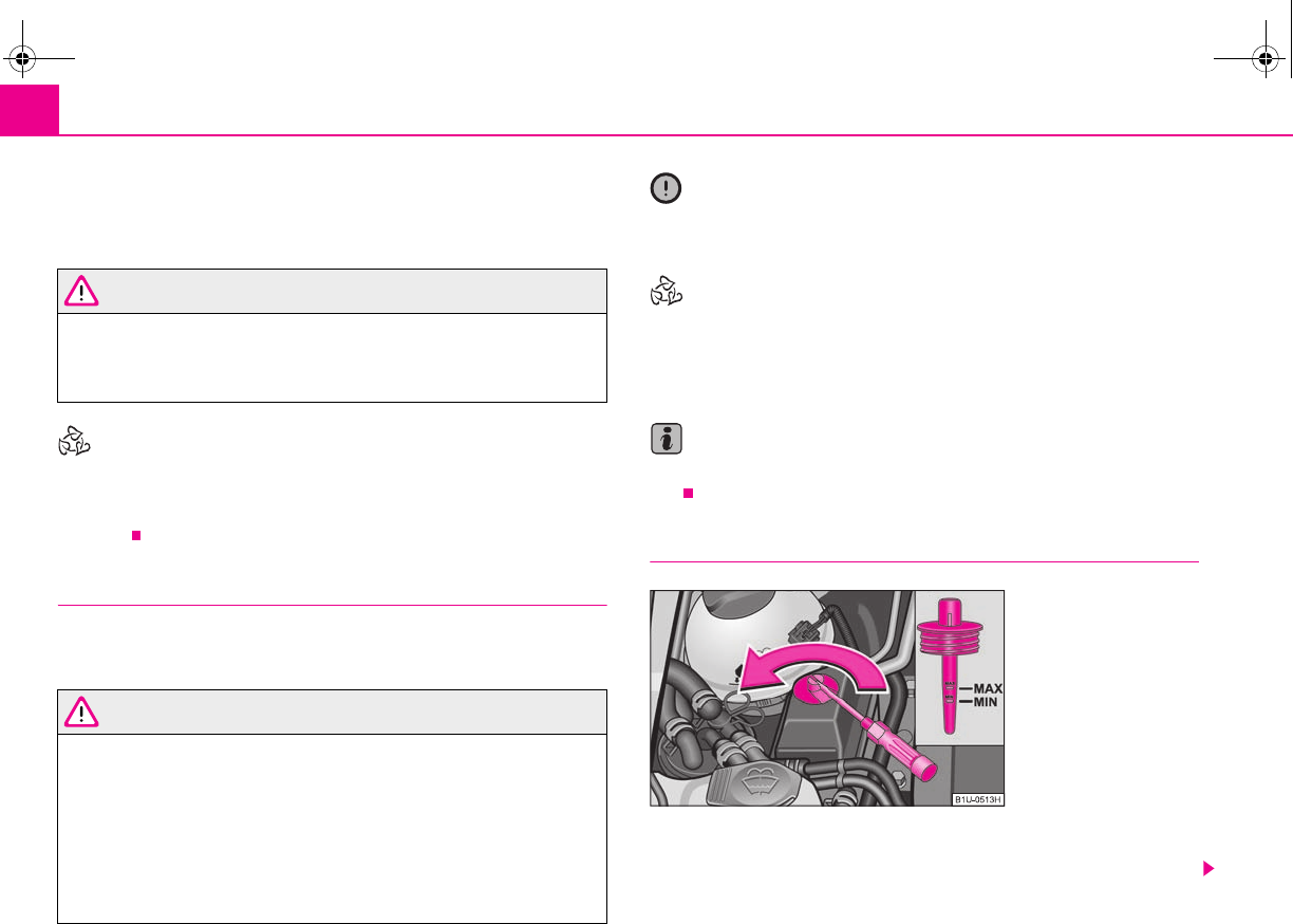
Inspecting and replenishing164
– Inspect the oil level ⇒page 163.
– Carefully screw on the cap of the filler opening and push the dipstick
in fully.
WARNING
•Avoid dripping oil onto hot parts of the engine when topping up will oil -
a risk of fire!
•Read and observe the warning notes ⇒page 160, “Working in the engine
compartment” before working in the engine compartment.
For the sake of the environment
The oil level must on no account be above the range ⇒page 163. Oil will other-
wise be drawn in through the crankcase ventilation and may pass through the
exhaust system to atmosphere. The oil may combust in the catalytic converter and
damage it.
Changing engine oil
The engine oil must be changed at the intervals stated in the Service schedule or
according to the service interval indicator ⇒page 18.
WARNING
•Only carry out the engine oil change, if you have the required profes-
sional knowledge!
•Read and observe the warning notes ⇒page 160, “Working in the engine
compartment” before working in the engine compartment.
•Let the engine cool down - risk of burning from hot oil.
•Wear an eye protection - risk of caustic burns due to oil splashes.
•Oil is toxic! Store old oil in a safe place out of the reach of children and
unauthorized persons until you dispose of it properly.
Caution
You must not pour any additives into the engine oil - risk of engine damage!
Damage, which results from such product, are excluded from the warranty.
For the sake of the environment
•You must on no account pour oil into the ground or into the sewage system.
•In view of the problems involved in properly disposing of old oil, the material,
equipment and the knowledge required for such work, we recommend that you
have the oil and oil filter change carried out by a specialist garage.
Note
After your skin has come in contact with the oil, you must thoroughly wash your
skin.
Power steering
The reservoir for hydraulic oil of power steering is located in the front right of the
engine compartment ⇒page 161, fig. 151.
A
a
Fig. 153 Hydraulic oil
dipstick
s2g8.b.book Page 164 Tuesday, April 7, 2009 8:53 AM
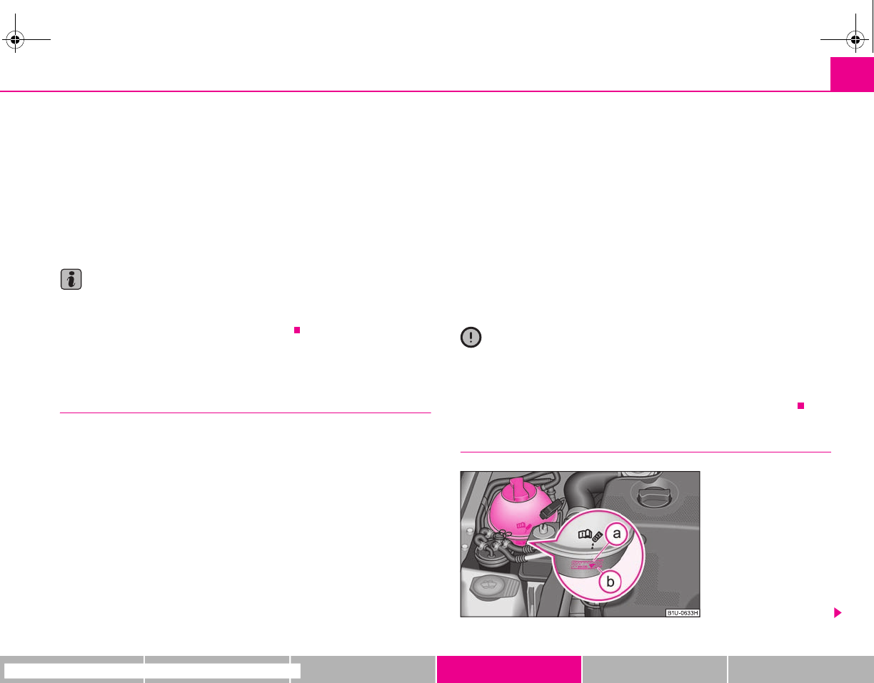
Inspecting and replenishing 165
riving Tips General Maintenance Breakdown assistance Technical Data
Check hydraulic oil
The hydraulic system of the power steering is filled with the hydraulic oil designated
in the catalogue as G 002 000.
Perform the inspection of the hydraulic oil level when the engine is cold and not
running.
The hydraulic oil level must be between the “MIN” and “MAX” markings
⇒page 164, fig. 153. If the level drops below the marking “MIN”, it is necessary that
the power steering is checked by a specialist garage. It is not sufficient to solely refill
with hydraulic oil.
Note
If the engine is not running (when towing) or if the V-ribbed belt is torn, the power
steering does not operate. The vehicle is fully steerable however. There is however
increased force required to turn the steering wheel.
Cooling system
Coolant
The job of the coolant is to cool the engine.
The cooling system does not require any maintenance under normal operating
conditions. The coolant consists of water with a concentration of coolant additive
of 40 %. This mixture not only provides antifreeze protection down to -25°C but
also protects the cooling and heating system from corrosion. It also prevents the
formation of scale and significantly increases the boiling point of the coolant.
You must therefore not reduce the concentration of antifreeze agent in the coolant
by adding water, also not during the summer months or in countries with a warm
climate. The concentration of coolant additive in the coolant must be at least
40%.
You can increase the amount of antifreeze in the coolant if a higher concentration
of antifreeze is necessary for climatic reasons but only up to 60% (antifreeze
protection down to approx. -40°C). The antifreeze protection tails off above that
concentration.
Vehicles exported to countries with a cold climate (e.g. Sweden, Norway, Finland)
are already factory-filled with a coolant which offers antifreeze protection down to
about -35°C. In these countries the concentration of coolant additive should be at
least 50 %.
Coolant
The cooling system is factory-filled with coolant (purple in colour), which complies
with the specification TL-VW 774 G.
We recommend that you use the same coolant additive - G12 PLUS-PLUS (purple
in colour) for topping up the system.
Please contact a specialist garage if you have any questions regarding the coolant
or if you wish to fill up with a different coolant.
A specialist garage can also supply you with the correct coolant additives.
Caution
•Other coolant additives may cause operational problems which, in partic-
ular, involves significantly reducing the anticorrosion effect.
•Any faults or problems resulting from corrosion may cause a loss of
coolant and, as a consequence of this, result in major engine damage.
Inspecting the coolant level
Fig. 154 Engine compart-
ment: Coolant expansion
bottle
s2g8.b.book Page 165 Tuesday, April 7, 2009 8:53 AM
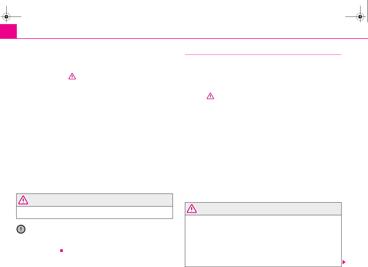
Inspecting and replenishing166
The coolant expansion bottle is located in the engine compartment on
the right.
– Switch the engine off.
– Open the bonnet ⇒ in “Working in the engine compartment” on
page 160.
– Check the level of coolant in the coolant expansion bottle
⇒page 165, fig. 154. When the engine is cold, the coolant level must
lie between the and markings. When the engine is warm, the
level may also lie slightly above the hatched part.
If the coolant level in the reservoir is too low, this is indicated by the warning light
in the instrument cluster ⇒page 30. We nevertheless recommend inspecting
the coolant level directly at the reservoir from time to time.
Loss of coolant
A loss of coolant is first and foremost an indication of a leak in the system. You
should not merely top up the coolant in the reservoir. It is also important to have
the cooling system inspected without delay by a specialist garage.
Losses can only occur through the pressure relief in the cap of the coolant expan-
sion bottle which is completely free of leaks if the coolant boils as a result of over-
heating and is forced out of the cooling system.
WARNING
Read and observe the warning notes ⇒page 160, “Working in the engine
compartment” before working in the engine compartment.
Caution
One should contact a specialist garage as soon as possible if the source of over-
heating itself cannot be determined and removed, since there may be grave
damage to the engine.
Replenishing the coolant
– Switch the engine off.
– Allow the engine to cool down.
– Place a cloth over the cap of the coolant expansion reservoir
⇒page 165, fig. 154 and unscrew the cap carefully by turning it to the
left ⇒.
– Top up the coolant.
– Screw the cap tight until it is heard to lock.
The coolant which you use for replenishing the system, must comply with one
specific specification ⇒page 165, “Coolant”. Do not use an alternative additive if
the coolant additive G12 PLUS - PLUS is not available in exceptional cases. Just top
up the system with water and as soon as possible arrange adjustment to correct the
mixing ratio of water and coolant additive again by a specialist garage.
Only use fresh coolant for topping up the system.
Do not top up the fluid above the hatched part! Excess coolant which is heated up
is forced out of the cooling system through the pressure relief valve in the cap of the
coolant compensation bottle.
Wait until the engine has cooled down for a system which has suffered a major loss
of coolant before pouring in coolant. This is necessary to avoid engine damage.
WARNING
•The cooling system is pressurized! Do not open the cap of the coolant
expansion bottle if the engine is still hot - risk of scalding!
•The coolant additive and thus all of the coolant is harmful to your health.
Avoid contact with the coolant. Coolant vapours are also harmful to the
health. It is important, therefore, to always safely store any coolant additive
in its original container out of the reach of children - risk of poisoning!
•If any splashes of coolant get into your eyes, rinse out your eyes immedi-
ately with clear water and contact a doctor as soon as possible.
A
a
A
b
s2g8.b.book Page 166 Tuesday, April 7, 2009 8:53 AM
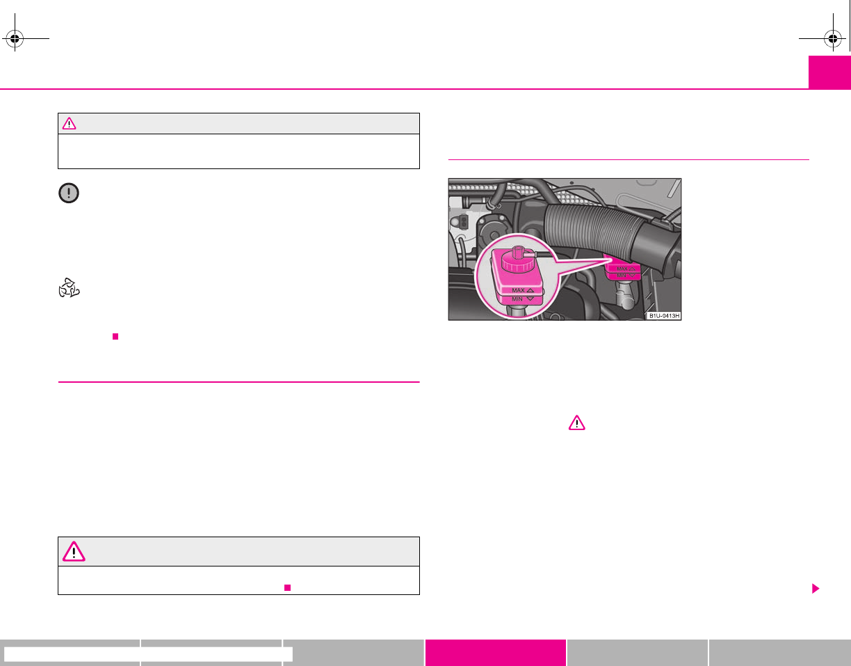
Inspecting and replenishing 167
riving Tips General Maintenance Breakdown assistance Technical Data
•You should also consult a doctor without delay if you have inadvertently
swallowed coolant.
Caution
Do not continue your journey if for some reason it is not possible under the
conditions prevailing to top up with coolant. Switch the engine off and obtain
professional assistance from a specialist garage, otherwise it could lead to severe
engine damage.
For the sake of the environment
Do not re-use coolant if it is necessary to drain the coolant in the system. It should
be collected and disposed of in compliance with environmental protection
regulations.
Radiator fan
The radiator fan may switch on suddenly.
The radiator fan is driven by an electric motor and controlled according to the
coolant temperature.
The radiator fan may continue running for up to 10 minutes after the engine has
been switched off - even if the ignition is also off. It may also switch on suddenly
after a certain time, if
•the coolant temperature has risen because of an accumulation of heat or
•the warm engine compartment is heated up additionally by strong sunlight.
WARNING
You must therefore be aware when working in the engine compartment that
the fan may switch on suddenly - risk of injury!
Brake fluid
Inspecting the brake fluid level
The brake fluid reservoir is located on the left of the engine compartment.
The brake fluid reservoir on right-hand steering models is positioned on
the other side of the engine compartment.
– Switch the engine off.
– Open the bonnet ⇒ in “Working in the engine compartment” on
page 160.
– Inspect the brake fluid level in the reservoir ⇒fig. 155. The level must
be between the “MIN” and “MAX” markings.
A slight drop in the fluid level results when driving due to normal wear-and-tear
and automatic adjustment of the brake pads, and is perfectly normal.
There may be an indication of a leak in the brake system, however, if the fluid level
drops significantly within a short time or if it drops below the “MIN” marking. A situ-
ation where the brake fluid level is too low is indicated by the warning light
lighting up in the instrument cluster ⇒page 34. In this case stop immediately and
do not drive any further! Obtain professional assistance.
WARNING (continued)
Fig. 155 Engine compart-
ment: Brake fluid reservoir
s2g8.b.book Page 167 Tuesday, April 7, 2009 8:53 AM
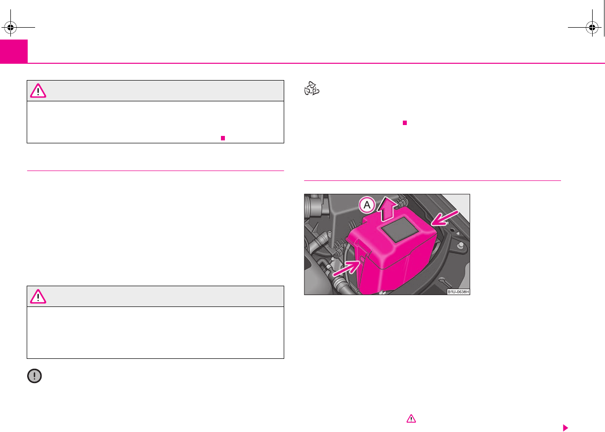
Inspecting and replenishing168
WARNING
•Read and observe the warning notes ⇒page 160, “Working in the engine
compartment” before working in the engine compartment.
•If the fluid level has dropped below the “MIN” marking, do not drive any
further - risk of accident! Obtain professional assistance.
Replacing brake fluid
Brake fluid absorbs moisture. This causes the fluid to absorb moisture from the
surrounding air over a period of time. Excessive water in the brake fluid may be the
cause of corrosion in the brake system. The water content also lowers the boiling
point of the brake fluid. This is why brake fluid must be replaced every two
years.
One may only use new genuine brake fluid from Škoda Auto. The specification for
the brake fluid is “FMVSS 116 DOT 4”.
We recommend that you have the brake fluid replaced by a specialist garage as
part of an Inspection Service.
WARNING
•Using old brake fluid can result in severe stress on the brakes because of
the formation of vapour bubbles in the brake system. This greatly impairs
the braking efficiency and thus also the safety of your vehicle.
•Brake fluid is toxic! It must therefore be kept safely in closed original
containers and well away from children and unauthorized persons.
Caution
Brake fluid damages the paintwork of the vehicle.
For the sake of the environment
In view of the problems involved with proper disposal of brake fluid, the special
tools and the professional knowledge required, you should have the brake fluid
replaced by a specialist garage.
Battery
Working on the battery
The battery is located in the engine compartment below a plastic cover*.
– Press the interlocks on the sides of the battery cover ⇒fig. 156 and
pull the cover upwards see arrow .
– The installation of the battery cover takes place in the reverse order.
Removal and installation of the battery is not recommended since it can, under
certain circumstances, lead to major damage. Contact a specialist garage.
There is a risk of injuries, scalding, accidents and burns when carrying out any work
on the battery and on the electrical system. For this reason, it is essential to comply
with the warning instructions ⇒ stated below and with the general applicable
rules of safety.
Fig. 156 Engine compart-
ment: The battery
A
A
s2g8.b.book Page 168 Tuesday, April 7, 2009 8:53 AM
Inspecting and replenishing 169
riving Tips General Maintenance Breakdown assistance Technical Data
WARNING
•The battery acid is strongly corrosive and must, therefore, be handled
with the greatest of care. Always wear protective gloves, eye and skin
protection when handling batteries. Corrosive fumes in the air irritate the
air passages and lead to conjunctivitis and inflammation of the air passages
in the lungs. Battery acid corrodes dental enamel and creates deep wounds
after contact with the skin which take a long time to heal. Repeated contact
with diluted acids causes skin diseases (inflammations, ulcers, slin cracks).
Acids coming into contact with water are diluted accompanied by significant
development of heat.
•Do not tilt the battery otherwise battery electrolyte may flow out of the
battery vent openings. Protect the eyes with safety glasses or a shield! There
is the danger of suffering blindness! If any battery electrolyte gets into your
eye, rinse out your eye immediately with clear water for several minutes.
Contact a doctor without delay.
•Splashes of acid on your skin or clothes should be neutralised as soon as
possible using soap suds and then rinsed with plenty of water. Contact a
doctor immediately if you swallow battery electrolyte.
•Keep batteries out of the reach of children.
•Hydrogen is released when you charge a battery and a highly explosive
gas mixture is produced. An explosion can be caused through sparkling over
during unclamping or loosening of the cable plug while the ignition is on.
•Bridging of the poles will create a short circuit (e.g. through metal
objects, cables). Possible consequences of a short circuit: Melting of lead
struts, explosion and burning of the battery, jets of acid spurting out.
•It is prohibited to work with a naked flame and light, to smoke or to carry
out any activities which produce sparks. Avoid creating sparks when
working with cables and electrical devices. Strong sparking represents a risk
of injury.
•Before carrying out any work on the electrical system, switch off the
engine, the ignition as well as all electrical components and disconnect the
negative cable (-) on the battery. If you wish to replace a bulb it is sufficient
to switch off the appropriate light.
•Never charge a frozen or thawed battery - risk of explosion and caustic
burns! Replace a frozen battery.
•Never use a battery which is damaged - risk of explosion! Immediately
replace a damaged battery.
Caution
•You must only disconnect the battery if the ignition is switched off, otherwise
the electrical system (electronic components) of the vehicle may be damaged.
When disconnecting the battery from the electrical system of the vehicle, first
disconnect the negative terminal (-) of the battery. Then disconnect the positive
terminal (+).
•When reconnecting the battery, first connect the positive terminal (+) and only
then the negative terminal (-) of the battery. You must on no account connect the
cables wrongly - risk of a cable fire.
•Ensure that battery acid does not come into contact with the vehicle body
otherwise damage could occur to the paintwork.
•Do not place the battery in direct daylight in order to protect the battery
housing from the effects of ultra-violet light.
For the sake of the environment
A removed battery is a special type of waste which is harmful to the environment -
contact your specialist garage regarding disposing of the battery.
Note
Please also refer to the guidelines ⇒page 171, “Disconnecting and reconnecting
the battery”, also after connecting the battery.
WARNING (continued)
s2g8.b.book Page 169 Tuesday, April 7, 2009 8:53 AM
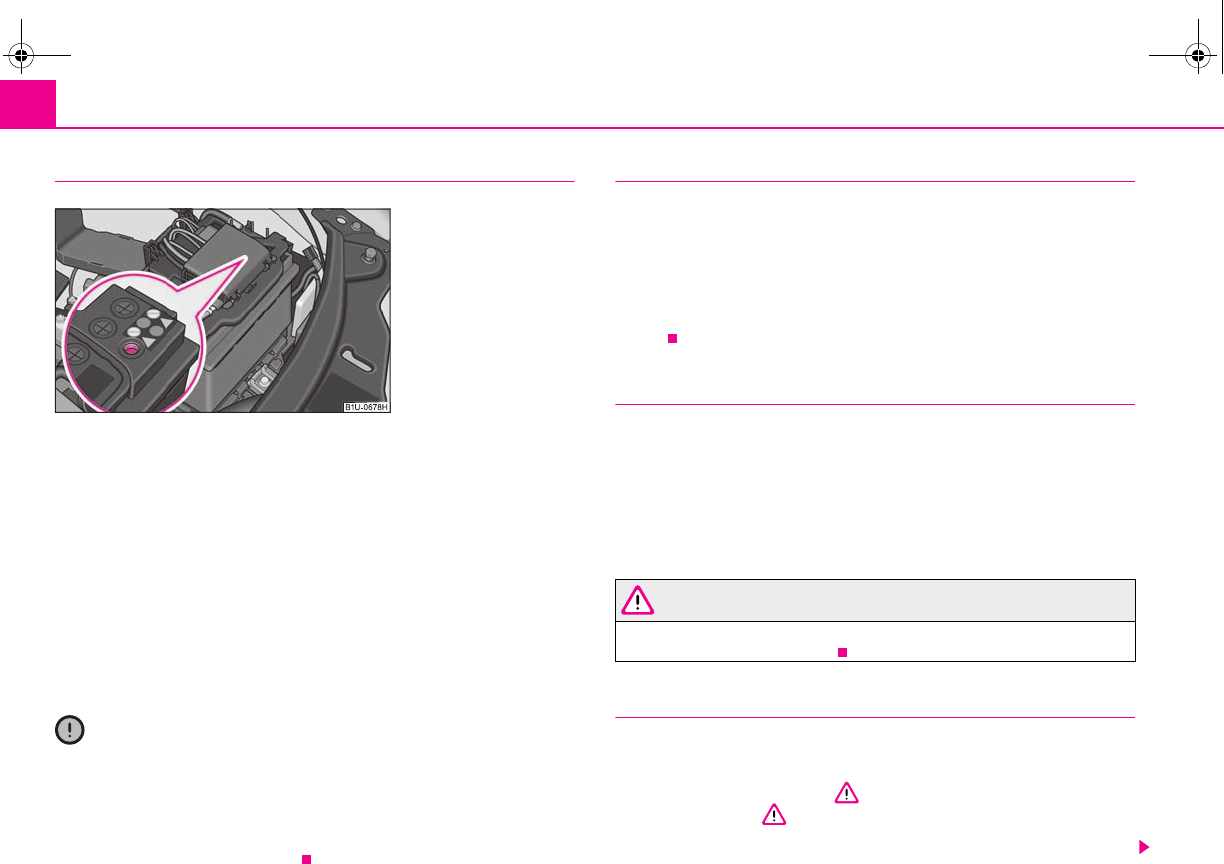
Inspecting and replenishing170
Battery with a charge level indicator, the so-called magic eye*
There is a so-called magic eye ⇒fig. 157 located on the top of the battery. The
“magic eye” changes its colour in line with the charge state and the electrolyte level
of the battery.
Air bubbles can influence the colour of the “magic eye”. For this reason carefully
knock on the “magic eye” before carrying out the check.
•Green colour - the battery is adequately charged.
•Dark colour - the battery has to be charged
•Colourless or yellow colour - have the battery checked by a specialist garage.
Batteries, which are more than 5 years old, must be replaced. We recommend you
have the electrolyte level inspected and adjusted to the correct level or the battery
replaced if necessary by a specialist garage.
Caution
If the vehicle has not been driven for more than 3 to 4 weeks, the battery will
discharge because certain electrical components consume electricity (e.g. control
units) also in idle state. You can prevent the discharging of the battery by discon-
necting the negative terminal or charging the battery constantly with a very low
charging current. Please also refer to the notes when working on the battery
⇒page 168, “Working on the battery”.
Inspecting the electrolyte level
The battery is practically maintenance-free under normal operating conditions.
We do, however, recommend that you have the electrolyte level inspected from
time to time by a specialist garage when outside temperatures are high or when
driving on long trips. You should also have the electrolyte level ⇒page 170
checked each time the battery is charged.
The electrolyte level of the battery will also be checked as part of the Inspection
Service.
Operation in winter
The battery has to provide greater amounts of electricity during the winter. It also
has only part of the initial power output at low temperatures that it has at normal
temperatures.
A discharged battery may already freeze at temperatures just below 0°C.
We therefore recommend that you have the battery checked by a specialist garage
before the start of the winter and recharged if necessary.
WARNING
Never charge a frozen or thawed battery - risk of explosion and caustic
burns. Replace a frozen battery.
Charging the battery
A properly charged battery is essential for reliably starting the
engine.
– Read the warning notes ⇒ in “Working on the battery” on
page 168 and ⇒.
– Switch the ignition and all electrical components off.
Fig. 157 Battery with a
charge level indicator
s2g8.b.book Page 170 Tuesday, April 7, 2009 8:53 AM
Inspecting and replenishing 171
riving Tips General Maintenance Breakdown assistance Technical Data
– Only for “quick-charging”: Disconnect both battery cables (first of all
“negative”, then “positive”).
– Carefully attach the terminal clamps of the charger to the battery
terminals (red = “positive”, black = “negative”).
– You can now plug the mains cable of the charger into the power socket
and switch on the charger.
– When charging is completed: switch the charger off and unplug the
mains cable from the power socket.
– Only then should you disconnect the terminal clamps of the charger.
– Reconnect the cables to the battery (first of all “positive”, then “nega-
tive”).
It is not normally necessary to disconnect the cables of the battery if you recharge
the battery using low amperages (as for example from a mini-charger). Please also
refer to the instructions from the charger manufacturer.
A charging current of 0.1 of the total battery capacity (or lower) is that which should
be used until full charging is achieved.
It is, however, necessary to disconnect both cables before charging the battery with
high amperages, so-called “quick-charging”.
“Quick-charging” a battery is dangerous ⇒ in “Working on the battery” on
page 168. It requires a special charger and appropriate knowledge. We therefore
recommend that you have your battery quick-charged only by your specialist
garage.
A discharged battery may already freeze at temperatures just below 0°C ⇒. We
recommend that you no longer use a battery which has thawed out because the
casing of the battery may be cracked through the formation of ice and this would
allow battery electrolyte to flow out.
The vent plugs of the battery should not be opened for charging.
WARNING
Never charge a frozen or thawed battery - risk of explosion and caustic
burns. Replace a frozen battery.
Disconnecting and reconnecting the battery
On disconnecting and reconnecting the battery the following functions are initially
deactivated or are no longer able to operate fault-free.
We recommend having the vehicle checked by a specialist garage to ensure full
functionality of all electrical systems.
Replacing the battery
You should only replace a battery with a new battery of the same capacity, voltage
(12 V), amperage and of the same size. Specialist garages have a range of suitable
batteries available.
We recommend that you only have an old battery disposed of by a specialist garage
since it does require special disposal.
For the sake of the environment
Batteries contain poisonous substances such as sulphuric acid and lead. They must
be disposed of in accordance with local environmental protection regulations and
on no account as domestic waste.
Operation Operating measure
Electrical power window (operational faults) ⇒page 46
Enter radio code number see Radio Operating Instructions
Set hours ⇒page 19
Data in the multi-functional indicator* are
deleted.
⇒page 19
s2g8.b.book Page 171 Tuesday, April 7, 2009 8:53 AM
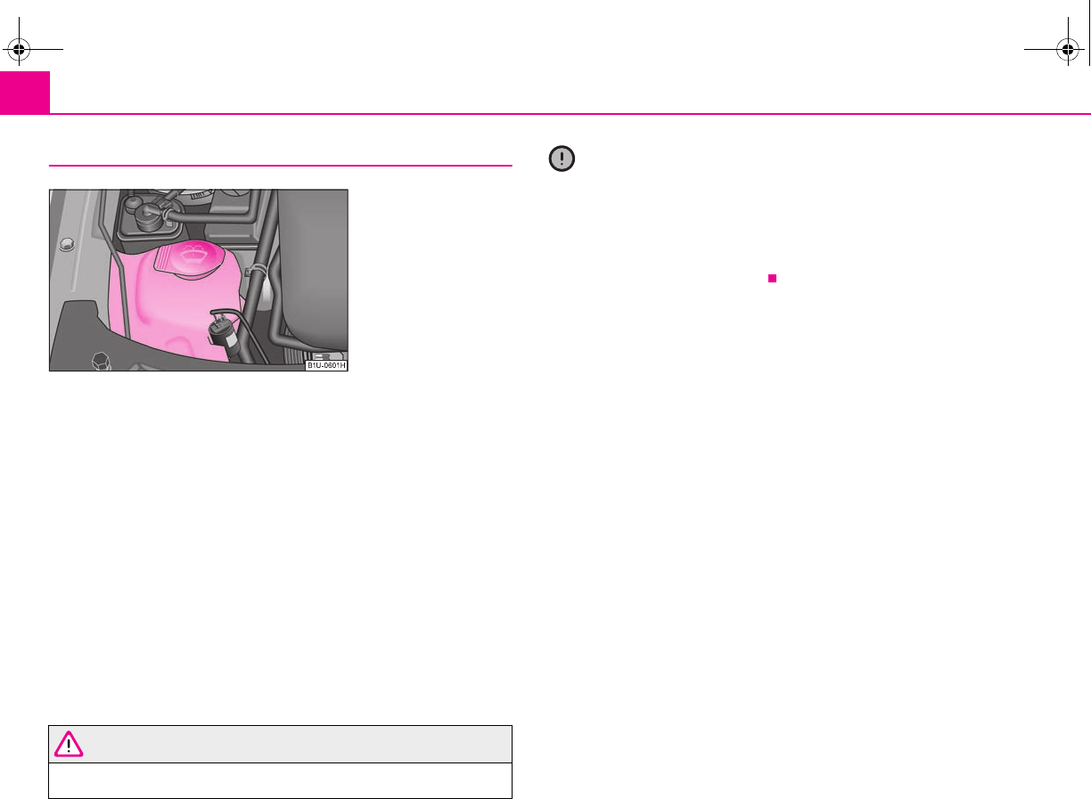
Inspecting and replenishing172
Windshield washer system
The windshield washer reservoir contains the cleaning fluid for the windscreen or
rear window. The reservoir is located at the front right of the engine compartment
⇒fig. 158.
The filling level of the container is 3 litres, 5.5 litres on vehicles which also have a
headlight washing system.
Clear water is not sufficient to intensively clean the windscreen and headlights. We
therefore recommend using clean washing water together with the screen cleaner
from Škoda genuine accessories (in winter additionally with antifreeze) which is
capable of removing stubborn dirt. Follow the instructions for use on the packaging
when using screen cleaning products.
You should always add antifreeze to the cleaning water in winter even if your
vehicle is fitted with heated windscreen washer nozzles*.
It is also possible in exceptional cases to use methylated spirits when no screen
cleaner with antifreeze is available. The concentration of methylated spirits must
not be more than 15 %. Please note, however, that the antifreeze protection at this
concentration is only adequate down to -5°C.
WARNING
Read and observe the warning notes ⇒page 160, “Working in the engine
compartment” before working in the engine compartment.
Caution
•On no account should you add radiator antifreeze or other additives to the
windscreen washer fluid.
•If the vehicle is fitted with headlight cleaning system, you should only add
cleaning products which do not attack the polycarbonate coating of the headlights
to the windscreen washer fluid. Please contact your specialist garage, who will tell
you which cleaning agent you can use.
Fig. 158 Engine compart-
ment: Windshield washer
fluid reservoir
s2g8.b.book Page 172 Tuesday, April 7, 2009 8:53 AM
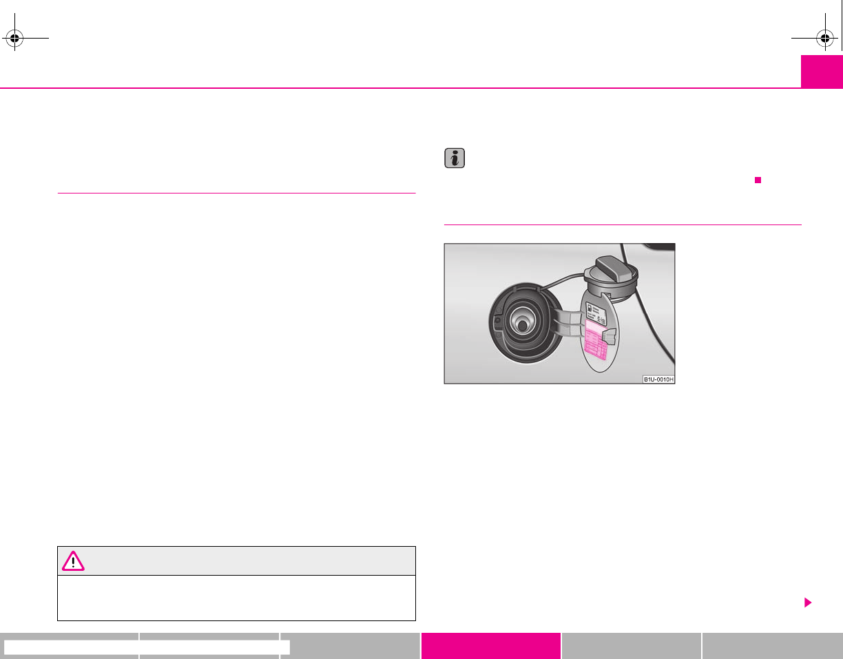
Wheels and Tyres 173
riving Tips General Maintenance Breakdown assistance Technical Data
Wheels and Tyres
Wheels
General information
•New tyres do not offer optimal grip at first and should therefore be run in for
about 500 km at a moderate speed and an appropriately cautious style of driving.
You will also profit from longer tyre life.
•The tread depth of new tyres may differ because of design features and the
configuration of the tread (depending on the type of tyre and the manufacturer).
•Drive over curbs on the side of the road and other such obstacles slowly and,
where possible, at a right angle in order to avoid damage to tyres and wheel trims.
•Inspect your tyres from time to time for damage (punctures, cuts, splits and
bulges). Remove foreign bodies from the tyre profile.
•Damage to tyres and wheels is frequently not visible. Unusual vibrations or
pulling of the vehicle to one side could be a sign of tyre damage. Please reduce
your speed immediately and stop if you suspect that a wheel is damaged.
Inspect the tyres for signs of damage (bulges, splits, etc.). If no visible damage is
present, please drive at an appropriately slow speed and carefully to the nearest
specialist garage in order to have your vehicle inspected.
•Also protect your tyres from contact with oil, grease and fuel.
•Immediately replace any dust caps of the valves which have got lost.
•Mark wheels before removing them so that their previous direction of running
can be maintained when mounted them again.
•Always store wheels or tyres which been removed in a cool, dry and, where
possible, dark place. Tyres which are not fixed to a wheel trim should be stored
upright.
WARNING
•New tyres during the first 500 km do not offer optimal grip and should
therefore be run appropriately - risk of accident!
•Never drive with damaged tyres - risk of accident!
Note
Please observe the various differing legal requirements regarding tyres.
Tyre life
The life of your tyres very much depends on the following points:
Tyre pressure
The working life of tyres will be shortened considerably if the tyres are insufficiently
or over-inflated and this will have an adverse effect on the handling of your vehicle.
Correctly inflated tyres are of particular importance when travelling at high speeds.
It is therefore good to check the pressure at least once a month and also before
setting off on a long trip. Please do not forget the spare wheel* when checking the
tyres.
The tyre inflation pressures for summer tyres are indicated on the inside of the fuel
filler flap ⇒fig. 159. The inflation pressures for winter tyres are 20 kPa (0.2 bar)
higher than those for summer tyres ⇒page 177.
The tyre pressure should be at the highest pressure specified for your vehicle at all
times.
Fig. 159 An opened fuel filler
flap with a tyre size and tyre
inflation pressure table
s2g8.b.book Page 173 Tuesday, April 7, 2009 8:53 AM
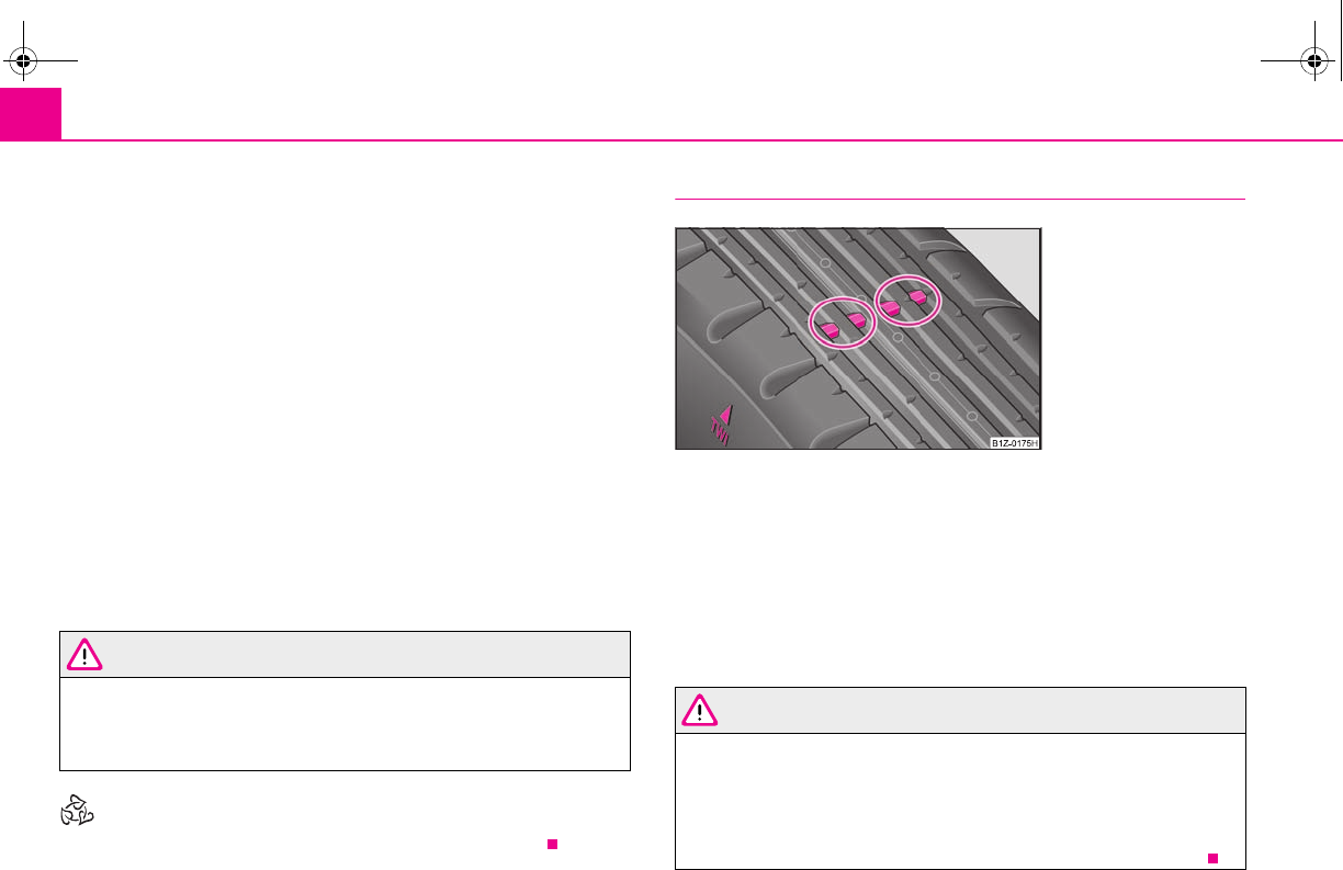
Wheels and Tyres174
Always check the inflation pressure of tyres when cold. Do not reduce the higher
pressure of warm tyres. Adapt the inflation pressure of the tyres accordingly if your
vehicle is carrying a significantly higher payload.
Driving style
Fast cornering, sharp acceleration and braking (squealing tyres) increase wear-and-
tear on your tyres.
Balancing wheels
The wheels of a new vehicle are balanced. There are a wide range of influences
when driving which may result in an imbalance and which makes themselves felt
through vibration in the steering.
You should have the wheels rebalanced since any imbalance increases wear-and-
tear on the steering, the suspension and tyres. A wheel must also be rebalanced
when a new tyre is fitted and each time a tyre is repaired.
Wheel alignment errors
Incorrect wheel alignment at the front and rear will not only increase wear-and-tear
on the tyres but will also has an adverse effect on vehicle safety. Contact your
specialist garage if you notice any unusual tyre wear.
WARNING
•If the inflation pressure is too low, the tyre must perform a greater flexing
work. At higher speeds the tyre will warm up as a result of this. This can
result in tread separation and even a tyre blowout.
•Immediately replace the damaged rims or tyres.
For the sake of the environment
Tyres which are insufficiently inflated increase your fuel consumption.
Wear indicators
The base of the tread of the original tyres has wear indicators 1.6 mm high, installed
at right angles to the direction of travel. These wear indicators are located at 6 - 8
points depending on the make and are evenly spaced around the circumference of
the tyre ⇒fig. 160. Markings on the walls of the tyres through the letters “TWI”,
triangular symbols or other symbols identify the position of the wear indicators.
A remaining tread of just 1.6 mm, measured in the grooves of the tread next to the
wear indicators, means that your tyres have reached their legally permissible
minimum tread depth.
WARNING
•You must have your tyres replaced with new ones at the latest when the
wear indicators have been worn down. The legally permissible minimum
tread depth should be observed.
•Worn tyres do not provide the necessary adhesion to the road surface at
high speeds on wet roads. One could experience “aquaplaning” (uncon-
trolled movements of the vehicle - “swimming” on a wet road surface).
Fig. 160 Tyre tread with wear
indicators
s2g8.b.book Page 174 Tuesday, April 7, 2009 8:53 AM
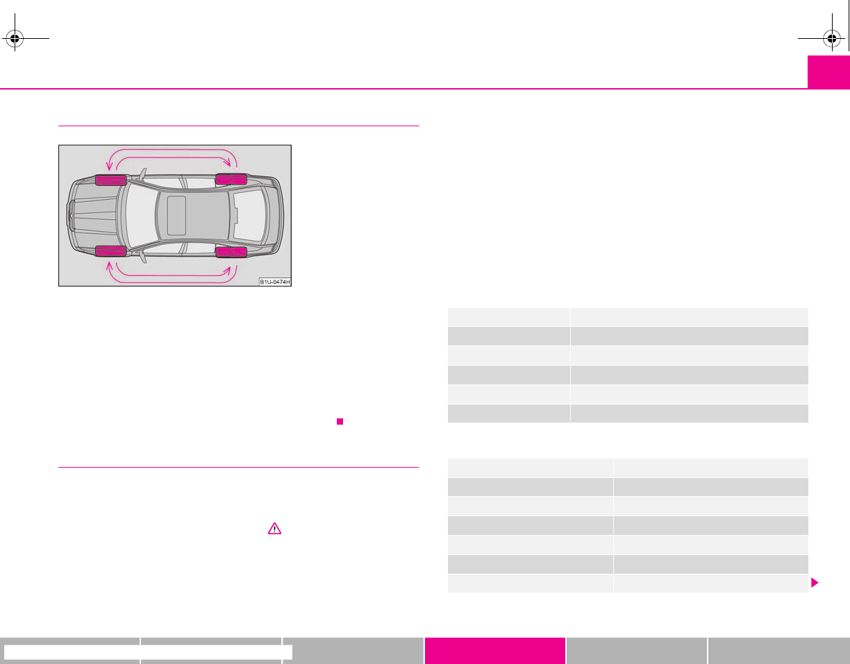
Wheels and Tyres 175
riving Tips General Maintenance Breakdown assistance Technical Data
Changing wheels around
If significantly greater wear is present on the front tyres, we recommend changing
the front wheels around with the rear wheels as shown in the diagram ⇒fig. 161.
You will then obtain approximately the same life for all the tyres.
It may be advantageous to swap the tyres over “crosswise” when certain types of
wear characteristic arise on the running surface of the tyres (but not in the case of
unidirectional tyres). Specialist garages are familiar with details.
We recommend that you change the wheels around every 10 000 km in order to
achieve even wear on all wheels and to obtain optimal tyre life.
New tyres and wheels
Tyres and wheel rims are important design elements. One should therefore use the
tyres and wheel rims which have been released for use by Škoda Auto. They are
exactly matched to the vehicle type and therefore contribute significantly to good
road holding and safe driving characteristics ⇒.
Only fit radial tyres of the same type on all 4 wheels, size (rolling circumference)
and, if possible, the same tread pattern on one axle.
The specialist garages have access to the most current information about which
tyres we have released for use on your vehicle.
We recommend that you have any work relating to tyres or wheels carried out by a
specialist garage. Specialist garages have all of the necessary special tools and
replacement parts available plus the required specialist knowledge and are also in
a position to properly dispose of the old tyres. A large number of specialist garages
also have an attractive range of tyres and wheels available.
The tyre/wheel combinations which are approved for your vehicle are indicated in
your vehicle documents. Approval and licensing may differ according to the legis-
lation prevailing in individual countries.
Proper knowledge of the tyre data makes it easier for you to select the correct type
of tyre. Tyres do, for example, have the following inscription on their walls:
195 / 65 R 15 91 T
What this means is:
The following speed restrictions apply to tyres.
Fig. 161 Changing wheels
around
195 Tyre width in mm
65 Height/width ratio in %
RCode letter for the type of tyre - R adial
15 Diameter of wheel in inches
91 Load index
TSpeed symbol
Speed symbol Permissible maximum speed
R170 km/h
S180 km/h
T190 km/h
H210 km/h
V240 km/h
W270 km/h
s2g8.b.book Page 175 Tuesday, April 7, 2009 8:53 AM
Wheels and Tyres176
The date of manufacture is also stated on the tyre wall (possibly only on the inside
of wheel):
DOT ... 50 08...
means, for example, that the tyre was manufactured in the 50th week of the year
2008.
If the spare wheel* differs from the tyres fitted to the vehicle (e.g. winter tyres or
low-profile tyres), the spare wheel* should only be used for a short time in the
event of a puncture and when adopting an appropriately cautious style of driving.
It should be replaced as quickly as possible by a normal wheel.
WARNING
•Only use those tyres or wheel rims which have been approved for your
model of Škoda Auto vehicle. Failure to observe this instruction will
adversely affect the road safety of your vehicle - risk of accident! Approval
and licencing of your vehicle on public roads may also become void as a
result.
•You must on no account drive at a higher speed than is permissible for
your tyres - risk of an accident resulting from tyre damage and loss of control
over your vehicle.
•Tyres which are 6 years old or more should only be fitted in exceptional
cases and when adopting an appropriately cautious style of driving.
•Never fit tyres which have already been used without having adequate
knowledge of their previous history. Tyres age even if they have not been
used at all or only very little. A spare tyre must only be used in exceptional
cases and only then when adopting an appropriately cautious style of
driving.
•Do not, where possible, replace individual tyres but at least replace them
on both wheels of a given axle at the same time. Always fit the tyres with the
deeper tread depth to the front wheels.
For the sake of the environment
Old tyres must be disposed of in conformity with the appropriate regulations.
Note
It is not normally possible to fit wheels from other models of cars for technical
reasons. This may also apply in certain circumstances to the wheels of the same
type of vehicle.
Wheel bolts
Wheels and wheel bolts are matched to each other in terms of design. Each time
you fit other wheels - e.g. light alloy wheels or wheels with winter tyres - you must
therefore also use the matching wheel bolts of the correct length and shape of
spherical cap. This is essential to ensure that the wheels are tightly fitted and that
the brake system operates properly.
If you retrofit wheel trims (or have this done), please also ensure that an adequate
flow of air remains assured for cooling the brake system.
The specialist garages are informed about the technical possibilities which exist
regarding converting or retrofitting wheels, tyres and wheel trims.
WARNING
•In case of incorrect treatment of the wheel bolts, the wheel can loosen
when the car is moving - risk of accident!
•The wheel bolts must be clean and must turn easily. However, they must
never be treated with grease or oil.
•If the wheel bolts are tightened to a too low tightening torque, the rim
can lossen when the car is moving - risk of accident! A tightening torque
which is too high can damage the bolts and threads and this can result in
permanent deformation of the contact surfaces on the rims.
Caution
The prescribed tightening torque of the wheel bolts for steel and light alloy wheels
is 120 Nm.
s2g8.b.book Page 176 Tuesday, April 7, 2009 8:53 AM
Wheels and Tyres 177
riving Tips General Maintenance Breakdown assistance Technical Data
Winter tyres
The handling of your vehicle will be significantly improved when driving on wintry
roads if you fit winter tyres. Summer tyres do not offer the same grip on ice, snow
and at temperatures below 7 °C because of their construction (width, rubber blend,
tread pattern). This particularly applies to vehicles which are equipped with low-
profile tyres or high-speed tyres (code index H or V on wall of tyre).
Winter tyres must be mounted on all four wheels to obtain the best handling char-
acteristics.
You must only fit those types of winter tyre which are approved for your vehicle. The
permissible sizes of winter tyres are stated in your vehicle documents. Approvals
may differ because of national legislation.
Please remember that the tyres should be inflated to 20 kPa (0.2 bar) more than is
the case for summer tyres ⇒page 173, fig. 159.
Winter tyres no longer offer the same winter performance once the tyre tread has
worn down to a depth of about 4 mm.
Ageing also causes winter tyres to lose most of their winter performance properties
- even in cases where the remaining tread depth is still clearly more than 4 mm.
Speed restrictions apply to winter tyres as well as to summer tyres ⇒page 175,
⇒.
You can fit winter tyres of a lower speed category to your vehicle provided that you
also do not drive faster than the permissible maximum speed for such tyres, even
if the possible maximum speed of your vehicle is higher. The corresponding tyre
category can damage the tyres when exceeding the permissible maximum speed.
Please pay attention to the notes if you decide to fit winter tyres ⇒page 173.
You can also fit so-called “all-year tyres” instead of winter tyres.
Please contact your specialist garage if there are any points which are not clear who
will be able to provide you with information regarding the maximum speed for your
tyres.
WARNING
You must on no account drive your car at more than the permissible
maximum speed for your winter tyres - risk of an accident resulting from
tyre damage and loss of control over your car.
For the sake of the environment
Fit your summer tyres on again in good time since summer tyres offer you better
grip and handling on roads which are free of snow and ice as well as ar tempera-
tures below 7 °C - the braking distance is shorter, there is less tyre noise, tyre wear
is reduced and fuel consumption is reduced.
Note
Please observe the various differing legal requirements regarding tyres.
Snow chains
Snow chains must only be mounted on the front wheels.
When driving on wintry roads, snow chains improve not only traction, but also the
braking performance.
For technical reasons, it is only permissible to fit snow chains with the following
wheel/tyre combinations:
Only use fine-link snow chains. They must not project more than 15 mm -
including the chain lock.
Remove the full wheel trims if you wish to fit snow chains to the wheels.
Wheel size Depth (D) Tyre size
6J x 14 38 mm 175/80
6J x 15 38 mm 195/65
5.5J x 16 36 mm 205/55
s2g8.b.book Page 177 Tuesday, April 7, 2009 8:53 AM
Wheels and Tyres178
Observe the national legal requirements relating to the maximum vehicle speed
with snow chains.
WARNING
Please pay attention to the information in the supplied fitting instructions of
the snow chain manufacturer.
Caution
You must take the chains off as soon as you drive on roads which are free of snow.
They adversely affect the handling of your vehicle, damage the tyres and are rapidly
destroyed.
Note
We recommend that you use snow chains from the Škoda genuine accessories.
s2g8.b.book Page 178 Tuesday, April 7, 2009 8:53 AM
Accessories, changes and replacement of parts 179
riving Tips General Maintenance Breakdown assistance Technical Data
Accessories, changes and replacement of parts
Accessories and replacement parts
Škoda vehicles have been built according to the latest discoveries in safety engi-
neering. Thus one should not change the condition in which the vehicle was deliv-
ered from the manufacturer without some thought.
The following guidelines should be observed when a vehicle is to be retrofitted with
accessories, have technical changes made to it or a part has to be replaced at some
time in the future.
•Advise should always be obtained from a specialist garage before buying any
accessories and before making any technical changes ⇒.
•This is particularly the case when accessories are bought in a foreign country.
•Škoda Genuine Accessories which have been released for use and Skoda orig-
inal parts can be bought from specialist garages that professionally undertake the
assembly of parts which were purchased there.
•All Škoda original accessories which are listed in the catalogue of original acces-
sories such as sliding/tilting roofs, spoilers, wheel rims etc. are homologized.
•Radios, aerials and other electrical accessories should only be installed by a
specialist garage.
•The guidelines issued by Škoda Auto must be observed when making technical
changes.
•This is to ensure that no technical damage occurs to the vehicle, that travelling
and operating safety are maintained and that the chnages are permissible. The
specialist garages also undertake this work professionally or refer it to another
specialist garage in special cases.
Any damage which is done caused by technical changes made without
consulting a Skoda dealer is excluded from the guarantee.
WARNING
•We advise you, in your own interest, to only use Škoda Genuine Accesso-
ries and Škoda original parts which have been expressly approved for use on
your Škoda. Reliability, safety and suitabiliity have been established for
these Škoda original parts.
•We cannot guarantee suitability of installation into your vehicle of other
products despite keeping a constant eye on market developments (also not
in the case where there is an attestation or permission can be produced).
Technical changes
Interference on the electronic components and their software can lead to opera-
tional faults. This interference can also impair not directly affected systems because
of the networking of the electronic components. This means that the operating
safety of your vehicle can be considerably jeopardized, a greater wear of vehicle
parts can occur and finally the vehicle registration documents expire.
We trust that you will understand that Škoda Auto cannot be liable for damage
resulting from unprofessional work.
We therefore recommend that you have all work carried out with Škoda original
parts at specialist garages.
WARNING
Work or modifications on your vehicle, which have been carried out unpro-
fessionally, can cause operational faults - risk of accident!
Vehicles of the group N1
The vehicle of the group N1 is a box car which is designed and manufactured for the
transportation of goods.
WARNING (continued)
s2g8.b.book Page 179 Tuesday, April 7, 2009 8:53 AM

Accessories, changes and replacement of parts180
s2g8.b.book Page 180 Tuesday, April 7, 2009 8:53 AM
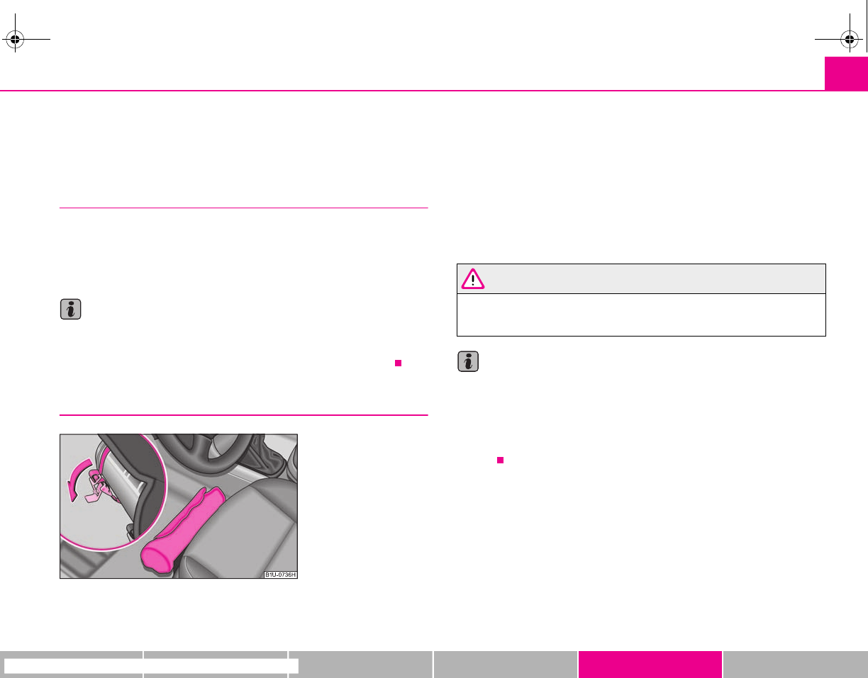
Breakdown assistance 181
riving Tips General Maintenance Breakdown assistance Technical Data
Breakdown assistance
Breakdown assistance
First-aid box*, Warning triangle* and bulb set*
A space for stowing the first-aid box and the bulb set is located in a well of the
plastic part under the floor covering of the luggage compartment behind the spare
wheel.
A space for the warning triangle is located in the luggage compartment.
Note
•Pay attention to the use-by-date of the contents of the first-aid box.
•If you equip your vehicle additionally with a warning triangle or with a first-aid
box, you can purchase these from the range of Škoda Original Accessories.
Fire extinguisher*
The fire extinguisher is attached with straps in a holder under the driver seat.
Please read carefully the instructions which are attached to the fire extin-
guisher.
The fire extinguisher must be checked by an authorised person or company annu-
ally (please observe the differing legal requirements).
WARNING
If the fire extinguisher is not correctly attached, in case of sudden manoeu-
vres or an accident it can be “thrown” through the interior compartment and
cause injuries.
Note
•The fire extinguisher must comply with the relevant and valid legal require-
ments.
•Pay attention to the expiration date of the fire extinguisher. If the fire extin-
guisher is used after the expiration date, its proper function is no longer assured.
•The fire extinguisher is only supplied in certain countries within the scope of
delivery.
Fig. 162 Placement of fire
extinguisher
s2g8.b.book Page 181 Tuesday, April 7, 2009 8:53 AM
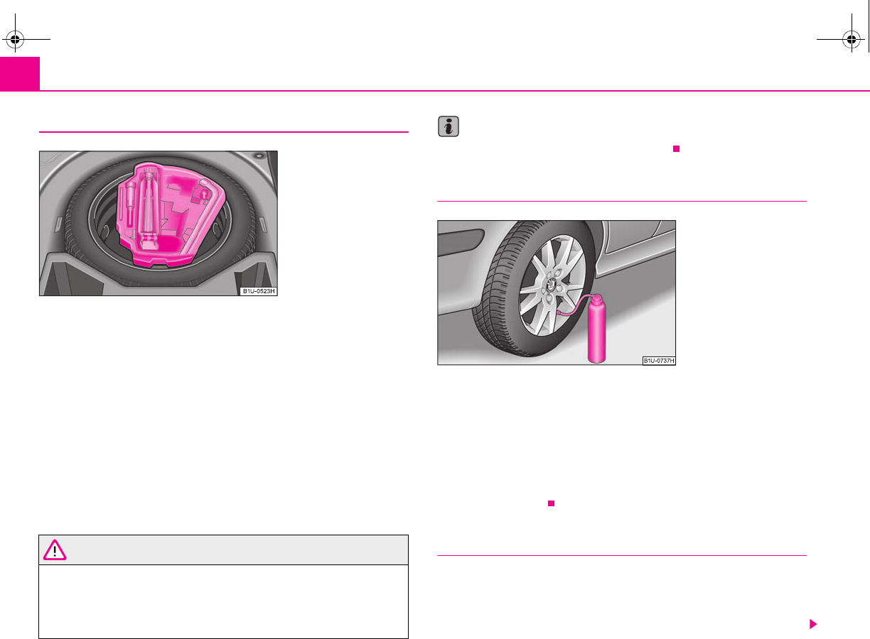
Breakdown assistance182
Vehicle tool kit
The vehicle tool kit and the lifting jack* are stowed in a box in the spare wheel*
⇒fig. 163; there is also space here for the detachable ball head of the towing
device*. The box is attached with a strap on the spare wheel*.
The vehicle tool kit contains the following parts (depending on equipment fitted):
•Wire clamps for removing the full wheel trims,
•Screwdriver,
•Plastic clip for a wheel bolt cover,
•Wheel wrench*,
•Towing eye,
•Adapter for the safety wheel bolts*.
Before placing the lifting jack* back in its storage area, screw in the arm of the lifting
jack fully.
WARNING
•The factory-supplied lifting jack* is only intended for your model of
vehicle. On no account attempt to lift a heavier vehicle or other loads - risk
of injury!
•Ensure that the vehicle tool kit is safely attached in the luggage compart-
ment.
Note
Ensure that the box is always secured with the strap.
Spray for repairing a tyre*
The spray for repairing a tyre is intended for rapid repair of small defects in a tyre
consisting of a damage up to a size of up to 5 mm. The spray is not at all intended
to replace a permanent repair on the tyre; this repair serves to reach the work-
shop.
The repair can be undertaken on the vehicle immediately. Please read the attached
instructions carefully before the repair.
The spray for repairing a tyre is located in the right front well of the plastic part
behind the spare wheel.
Tyre repair kit
The tyre repair kit is intended for the repair of minor tyre defects. The tyre repair kit
contains a compressor, inflation bottle, operating instructions and accessories.
The repair with the tyre repair kit is not at all intended to replace a permanent
repair on the tyre, this repair only serves to reach the next specialist garage. The
Fig. 163 Luggage compart-
ment: storage compartment
for vehicle tool kit
Fig. 164 Vehicle tool kit:
Spray for repairing a tyre
s2g8.b.book Page 182 Tuesday, April 7, 2009 8:53 AM
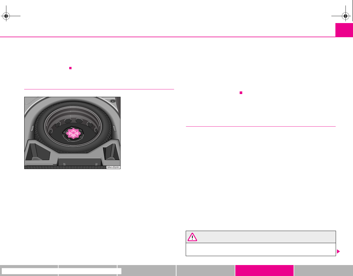
Breakdown assistance 183
riving Tips General Maintenance Breakdown assistance Technical Data
repair can be undertaken on the vehicle immediately. Please read the attached
instructions carefully before the repair.
The spray for repairing a tyre is located in the right front well of the plastic part
behind the spare wheel.
Spare wheel*
The spare wheel lies in a well under the floor covering of the luggage compartment
and is fixed in place using special screws ⇒fig. 165.
Before removing the spare wheel, you must take out the box with the vehicle tool
kit box ⇒page 182, fig. 163.
One should check the inflation pressure in the spare wheel (at best when generally
checking the tyre air pressures - see sign on the fuel filler flap ⇒page 173) to
ensure that the spare wheel is always ready to use.
Temporary spare wheel
A warning label displayed on the rim of the temporary spare wheel indicates that
your vehicle is equipped with a temporary spare wheel.
Please observe the following notes when driving with a temporary spare wheel:
•The warning label must not be covered after installing the wheel.
•Do not drive faster than 80 km/h with this spare wheel and pay particular atten-
tion while driving. Avoid accelerating at full throttle, sharp braking and fast
cornering.
•The inflation pressure for this spare wheel is identical to the inflation pressure
of the standard tyres.
•Use this spare wheel only to reach the nearest specialist garage as it is not
intended for continuous use.
Changing a wheel
Preliminary work
The following steps should be carried out before actually changing the
wheel.
– If it is necessary to change a wheel, park the vehicle as far away as
possible from the traffic flow. The place you choose should be level.
–Have all the occupants get out. While changing a wheel, the occu-
pants of the vehicle should not stand on the road (e.g. behind a crash
barrier).
– Apply the handbrake firmly.
– Shift up into the 1st gear.
– If a trailer is coupled, uncouple it.
– Take the vehicle tool kit ⇒page 182 and the spare wheel*
⇒page 183 out of the luggage compartment.
WARNING
•If you find yourself in flowing traffic switch on the hazard warning lights
system and place the warning triangle on the side of the road at the
Fig. 165 Luggage compart-
ment: Spare wheel
s2g8.b.book Page 183 Tuesday, April 7, 2009 8:53 AM
Breakdown assistance184
prescribed distance from your vehicle while observing all national legal
provisions. In this way you are protecting not only yourself but also other
road users.
•Never start the engine with the vehicle sitting on the raised jack - danger
of suffering injury.
Caution
If you have to change a wheel on a slope first block the opposite wheel with a stone
or similar object in order to secure the vehicle from unexpectedly rolling away.
Note
Comply with the national legal regulations.
Changing a wheel
Always change a wheel on a level surface as far as possible.
– Take off the full wheel trim* ⇒page 185 or the caps ⇒page 185.
– In the case of light alloy wheels remove the wheel trim cap
⇒page 186.
– Slacken the wheel bolts ⇒page 186.
– Jack up the vehicle until the wheel to be changed is clear of the ground
⇒page 187.
– Unscrew the wheel bolts and place them on a clean surface (cloth,
paper etc.).
– Take off the wheel.
– Fit on the new spare wheel* and tighten the wheel bolts slightly.
–Lower the car.
– Tighten the wheel bolts firmly, alternately and diagonally using the
wrench* (crosswise) ⇒page 186.
– Mount the full wheel trim/wheel trim cap or the caps.
Note
•All bolts must be clean and must turn easily.
•You must never grease or oil the wheel bolts!
•When fitting on unidirectional tyres, ensure that the tyres rotate in the correct
direction ⇒page 173.
Subsequent steps
After changing the wheel, you must perform the following steps.
– Stow and attach the replaced wheel in the spare wheel well.
– Stow the vehicle tool kit in the space provided.
–Check the tyre pressure on the spare wheel* just mounted as soon
as possible.
– Have the tightening torque of the wheel bolts checked with a torque
wrench as soon as possible. Steel and light alloy wheels must be tight-
ened to a tightening torque of 120 Nm.
– Have the defective tyre repaired as soon as possible.
WARNING
It is necessary to observe the guidelines given on ⇒page 175, “New tyres
and wheels” if the vehicle is subsequently fitted with tyres which are
different to those it was fitted with at the works.
WARNING (continued)
s2g8.b.book Page 184 Tuesday, April 7, 2009 8:53 AM
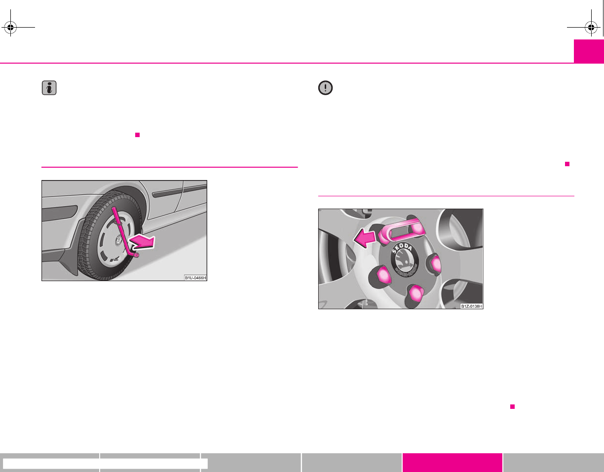
Breakdown assistance 185
riving Tips General Maintenance Breakdown assistance Technical Data
Note
•If you find, when changing the wheel, that the wheel bolts are corroded and
difficult to turn, the bolts must be replaced before checking the tightening torque.
•Drive cautiously and only at a moderate speed to a workshop where the tight-
ening torque can be checked.
Full wheel trim*
Pulling off
– Hook the clamp found in the vehicle tool kit into the reinforced edge
of the full wheel trim.
– Push the wheel wrench* through the clamp, support the wheel
wrench at the tyre and pull off the wheel trim ⇒fig. 166.
Installing
– First press the full wheel trim onto the wheel at the valve opening
provided. Then press the full wheel trim into the wheel in such a way
that its entire circumference locks correctly in place.
Caution
•Use the pressure of your hand, do not knock on the full wheel trim! Heavy
knocks mainly on the points where the full wheel trim has not been inserted into
the wheel, can result in damage to the guide and centering elements of the full
wheel trim.
•Check for yourself that the safety wheel bolt* is located in the hole in the area
of the valve before fitting the full wheel trim onto a steel wheel which is attached
with a safety wheel bolt* ⇒page 187, “Securing wheels against being stolen*”.
Wheel bolts with caps*
Pulling off
– Push the plastic clip sufficiently far onto the cap until the inner catches
of the clip are positioned at the collar of the cap and detach the cap.
Installing
– Push the caps fully onto the wheel bolts.
The caps are located in the well of the luggage compartment.
Fig. 166 Removing the full
wheel trim
Fig. 167 Removing the cap.
s2g8.b.book Page 185 Tuesday, April 7, 2009 8:53 AM
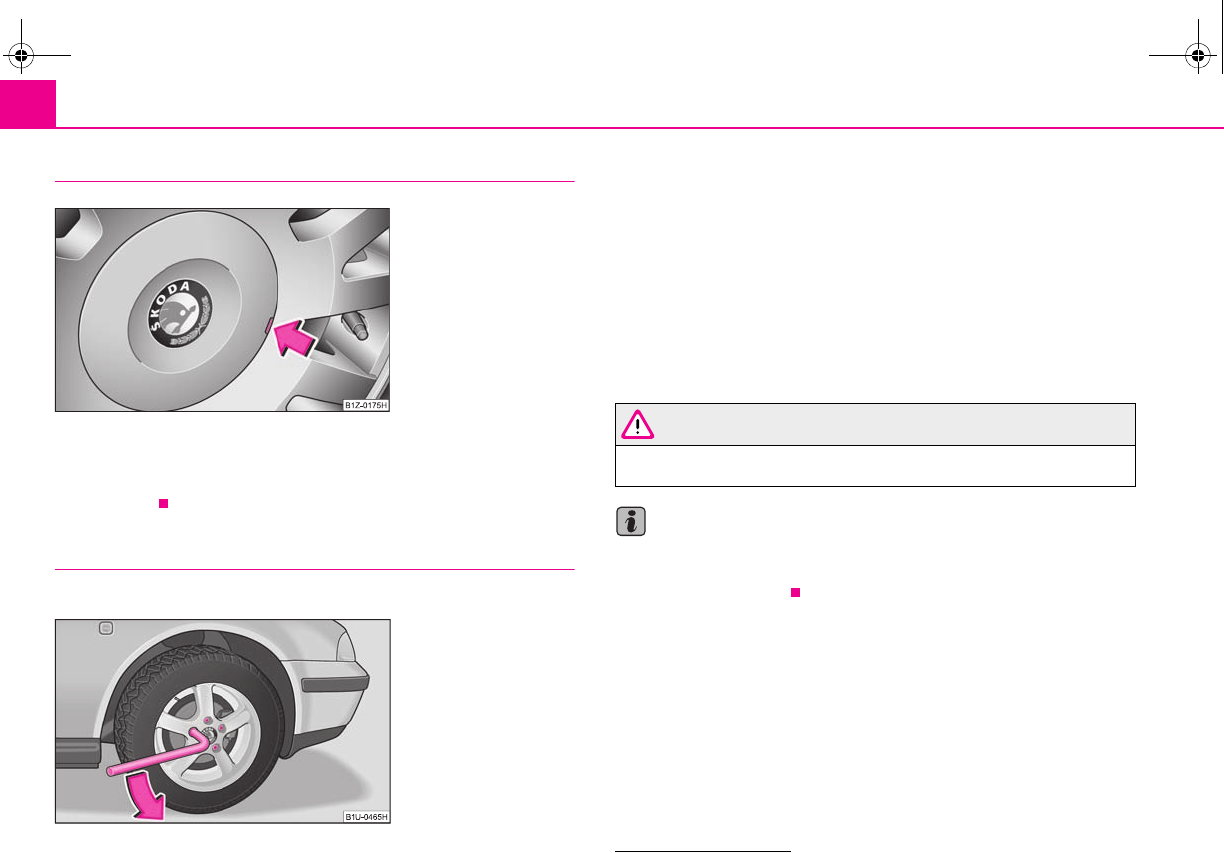
Breakdown assistance186
Wheel trim caps*
Pulling off
– Carefully remove the wheel trim cap using the wire clamp
⇒fig. 168.
Slackening and tightening wheel bolts
Slacken the wheel bolts before jacking up the vehicle.
Slackening wheel bolts
– Push the wheel wrench* fully onto the wheel bolt 6).
– Grasp the end of the wrench* and turn the bolt about one turn to the
left ⇒fig. 169.
Tightening wheel bolts
– Push the wheel wrench* fully onto the wheel bolt 6).
– Grasp the end of the wrench* and turn the bolt to the right until it is
tight.
WARNING
Slacken the wheel bolts only a little (about one turn) as long as the vehicle
has not yet been lifted with the lifting jack* - risk of accident!
Note
Apply pressure carefully with your foot to the end of the wrench* if it proves diffi-
cult to slacken the bolts. Hold tight on the vehicle when doing this and ensure that
you have a steady position.
Fig. 168 Pulling off wheel
trim cap on light alloy wheels
Fig. 169 Changing a wheel:
Slackening wheel bolts
6) Use the appropriate adapter for slackening and tightening the safety wheel bolts
⇒page 187.
s2g8.b.book Page 186 Tuesday, April 7, 2009 8:53 AM
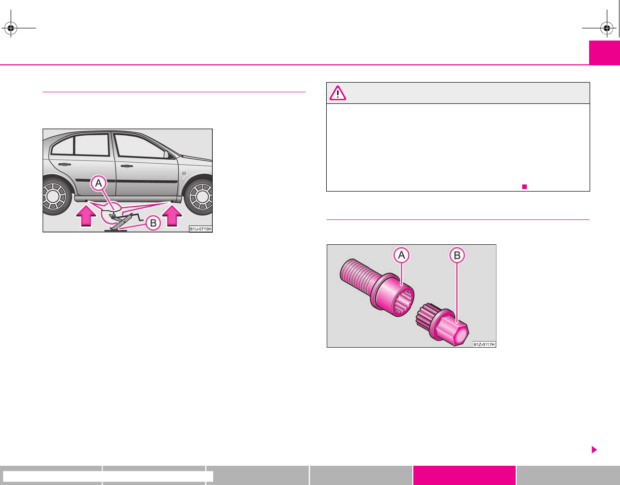
Breakdown assistance 187
riving Tips General Maintenance Breakdown assistance Technical Data
Raise vehicle
You have to raise the vehicle with the lifting jack* in order to be able
to take off the wheel.
Place the jack* under the vehicle. Recesses are located at the lower sill
(front and rear) ⇒fig. 170. There is a point under the recess where the
lifting jack* can be positioned, see arrows ⇒fig. 170.
– Position the lifting jack* below the jacking point and move it up until
its claw is positioned directly below the vertical web of the lower sill.
– Position the lifting jack* so that the claw grasps the web of the lower
sill and the moving base plate of the lifting jack is resting flat
against the floor.
– Turn the lifting jack* up further until the wheel is just clear of the
ground.
Ground below the lifting jack which is soft and slippery can cause the vehicle to
slip off the jack. It is therefore always necessary to place the lifting jack* on a solid
surface or use a wide and stable base. Use a non-slip base (e.g. a rubber foot mat)
if the surface is smooth, such as cobbled stones, a tiled floor, etc.
WARNING
•Always raise the vehicle with the doors closed - risk of injury!
•Take suitable measures to prevent the base of the lifting jack from slip-
ping off - risk of injury!
•Not positioning the lifting jack* at the specified points can result in
damage to the vehicle. The jack can also slip off if it does not have sufficient
grip - risk of injury!
•It is important to support the vehicle with suitable supporting blocks if
you wish to work under the lifted vehicle - risk of injury!
Securing wheels against being stolen*
You need a special adapter for slackening the safety wheel bolts.
– Pull off the full wheel trim/cap from the wheel hub or cap from the
safety wheel bolt.
– Insert the adapter with its toothed side fully into the inner toothing
of the safety wheel bolt right down in such a way that only the
outer hexagon is jutting out ⇒fig. 171.
– Insert the wheel wrench fully onto the adapter .
– Slacken the wheel bolt, or tighten it firmly ⇒page 186.
Fig. 170 Changing a wheel:
Jacking points for positioning
lifting jack
A
A
A
BFig. 171 Safety wheel bolt
with adapter
A
B
A
A
A
B
s2g8.b.book Page 187 Tuesday, April 7, 2009 8:53 AM
Breakdown assistance188
– Reinstall the full wheel trim/wheel cap after removing the adapter or
place the cap onto the safety wheel bolt.
– Have the tightening torque checked with a torque wrench as soon as
possible. Steel and light alloy wheels must be tightened to a tightening
torque of 120 Nm.
The safety wheel bolts on vehicles fitted with them (one safety wheel bolt per
wheel) can only be loosened or tighten up by using the adapter provided.
It is meaningful to note the code number hammered into the rear side of the
adapter or the rear side of the safety wheel bolts. You can obtain a replacement
adapter from a specialist garage, if necessary, by quoting this number.
We recommend that you always carry the adapter for the wheel bolts with you in
the vehicle. It should be stowed in the vehicle tool kit.
Caution
Damage can occur to the adapter and safety wheel bolt if the safety wheel bolt is
tightened up too much.
Note
The set of safety wheel bolts can be obtained from a specialist garage.
Jump-starting
Initial steps
You can use the battery of another vehicle for jump-starting yours if the engine
does not start because the battery on your vehicle is flat. You will require jump-start
cables for this purpose.
Both batteries must have a rated voltage of 12 V. The capacity (Ah) of the battery
supplying the power must not be significantly less than the capacity of the
discharged battery in your vehicle.
Jump-start cables
Only use jump-start cables which have an adequately large cross-section and insu-
lated terminal clamps. Please pay attention to the manufacturer's instructions.
Positive cable - colour coding in the majority of cases red.
Negative cable - colour coding in the majority of cases black.
WARNING
•A discharged battery may already freeze at temperatures just below 0°C.
In case of frozen battery carry out no jump-starting - risk of explosion!
•Please pay attention to the warning instructions relating to working in
the engine compartment ⇒page 160.
Note
•There must not be any contact between the two vehicles otherwise current may
flow as soon as the negative terminals are connected.
•The discharged battery must be properly connected to the system of the
vehicle.
•Switch off any mobile phone, pay attention to the instructions for use of the
mobile phone in such a situation.
•We recommend purchasing jump-start cables from Škoda Service Partners as a
Škoda original accessory or from retailers who sell branded batteries.
s2g8.b.book Page 188 Tuesday, April 7, 2009 8:53 AM
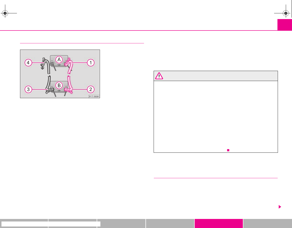
Breakdown assistance 189
riving Tips General Maintenance Breakdown assistance Technical Data
Start engine
It is important to connect the jump-start cables in the correct order.
Connecting positive terminals
– Attach one end to the positive terminal ⇒fig. 172 of the
discharged battery .
– Attach the other end to the positive terminal of the battery
supplying the power .
Connecting negative terminal and engine block
– Attach one end to the negative terminal of the battery supplying
the power .
– Attach the other end to a solid metal part which is connected
firmly to the engine block, or to the engine block itself.
Starting engine
– Start the engine of the vehicle providing current and run the engine at
idling speed.
– Now start the engine of the vehicle with the discharged battery.
– Interrupt the attempt at starting an engine after 10 seconds if it does
not start right away and wait for about 30 seconds before repeating
the attempt.
– Disconnect the cables on the engine in exactly the reverse order they
were connected up.
WARNING
•The non-insulated parts of the terminal clamps must never make contact
with each other. Furthermore, the cable connected to the positive terminal
of the battery must not come into contact with electrically conducting parts
of the vehicle - risk of a short circuit!
•Do not affix the jump starting cables to the negative terminal of the
discharged battery. There is the risk of detonating gas seeping out the
battery being ignited by the strong spark which results from the engine
being started.
•Run the jump-start cables so that they cannot be caught by any rotating
parts in the engine compartment.
•Do not bend over the batteries - risk of caustic burns!
•The vent screws of the battery cells must be tightened firmly.
•Keep any sources of ignition (naked flame, smouldering cigarettes etc.)
away from the battery - risk of an explosion!
Tow-starting and towing vehicle
General
Please pay attention to the following instructions if you are going to use a
tow rope:
Driver of the towing vehicle
– Do not drive off until the tow rope is taught.
Fig. 172 Jump-starting using
the battery from another
vehicle: A - flat vehicle
battery, B - battery providing
current
A
1
A
A
A
2
A
B
A
3
A
B
A
4
s2g8.b.book Page 189 Tuesday, April 7, 2009 8:53 AM
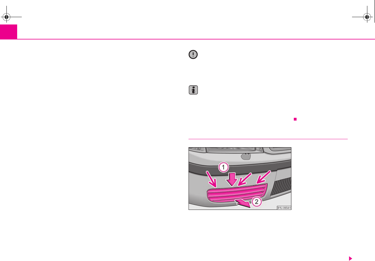
Breakdown assistance190
– Release the clutch particularly gently when starting off.
Driver of the towed vehicle
– Switch the ignition on so that the steering wheel is not blocked and
you can also operate the turn signal lights, the headlight flasher, the
windscreen wipers and windscreen washer system.
– Take the vehicle out of gear.
– Note that the brake servo unit and power steering only operate if the
engine is running. You will require significantly greater physical force
to depress the brake pedal and to steer the vehicle if the engine is not
running.
– Ensure that the tow rope is always kept taught.
Tow rope or tow bar
A tow bar is safest way of towing a vehicle and also minimizes any shocks. You can
use a tow rope only if a suitable tow bar is not available.
The tow rope must be elastic to protect the vehicle. Thus one should only use
plastic fibre rope or a rope made out of a similarly elastic material.
Only attach the tow rope to the towing eyes provided for this purpose ⇒page 190,
“Front towing eye”.
Driving style
Towing another vehicle requires a certain amount of practice. Both drivers should
be familiar with the particular points about towing a vehicle. Unskilled drivers
should not attempt to tow in another vehicle or to be towed in.
One should be constantly vigilant not to allow impermissibly high towing forces or
jerky loadings. There is always a risk of excessive stresses and damage resulting at
the points to which you attach the tow rope or tow bar when you attempt to tow a
vehicle which is not standing on a paved road.
Caution
If the gearbox of your vehicle no longer contains any oil because of a defect, your
vehicle must only be towed in with the driven wheels raised clear of the ground, or
on a special vehicle transporter or trailer.
Note
•Please comply with any legal requirements particularly regarding the switched
on signal systems, when towing in or tow-starting another vehicle.
•The tow rope must not be twisted as it may in certain circumstances result in the
front towing eye being unscrewed out of your vehicle.
Front towing eye
The front towing eye is welded on behind the bumper on the right
⇒fig. 173. The tow rope or the tow bar must only be attached to this eye.
The grille is secured with plastic lugs at the points of the arrows. Remove
the grille as follows:
– Grasp the grille on the ribs in the upper area. Press it in the direction
of arrow and take it out in the direction or arrow ⇒fig. 173.
Fig. 173 Front bumper:
protective grille of towing eye
A
1
A
2
s2g8.b.book Page 190 Tuesday, April 7, 2009 8:53 AM
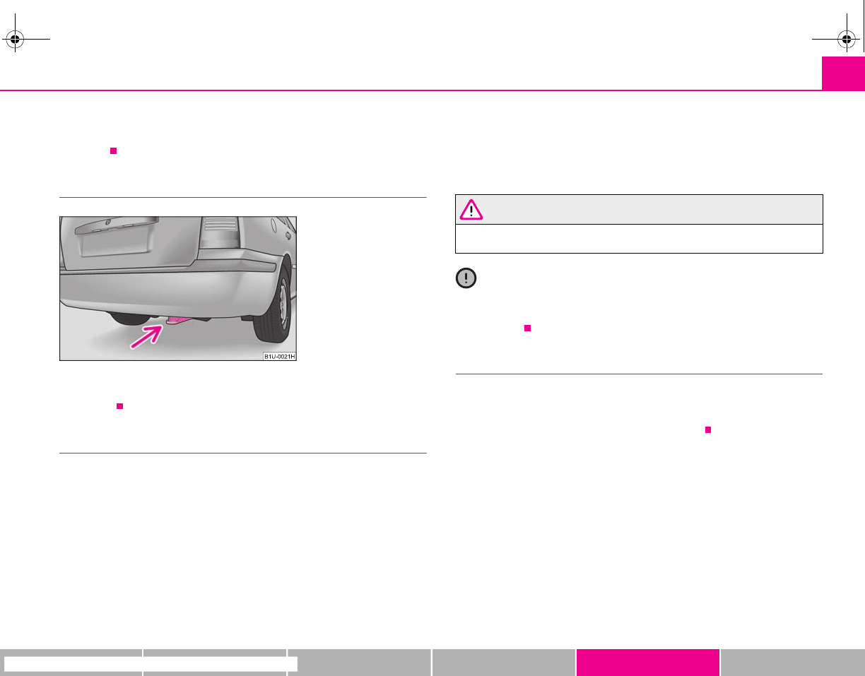
Breakdown assistance 191
riving Tips General Maintenance Breakdown assistance Technical Data
– Install again by positioning first of all the lugs of the grille in the guides
on the vehicle and press in the grille. The protective grille must engage
firmly.
Rear towing eye
The rear towing eye is located below the rear bumper on the right
⇒fig. 174.
Tow-starting a vehicle
If the engine does not start, we generally do not recommend to tow-start
your vehicle. One should attempt to start the engine using jump start
cables ⇒page 188 or call on the services of the SERVICE mobile.
If your vehicle has to be towed:
– Engage 2nd or 3rd gear with the vehicle stationary.
– Depress the clutch pedal fully and keep it depressed.
– Switch on the ignition.
– Wait until both vehicles are moving then release the clutch pedal
slowly.
– Depress the clutch pedal fully when the engine fires and take the
vehicle out of gear.
WARNING
There is high risk of having an accident when tow-starting a vehicle, when
for example the towed vehicle runs into the towing vehicle.
Caution
Vehicles which are fitted with a catalytic converter should not be tow-started over
a distance of more than 50 metres. Unburnt fuel may get into the catalytic converter
and damage it.
Towing in a vehicle fitted with a manual gearbox
Please refer to the notes ⇒page 189.
The vehicle can be towed in with a tow bar or a tow rope or with the front or rear
wheels raised. The maximum towing speed is 50 km/h.
Fig. 174 Rear towing eye
s2g8.b.book Page 191 Tuesday, April 7, 2009 8:53 AM
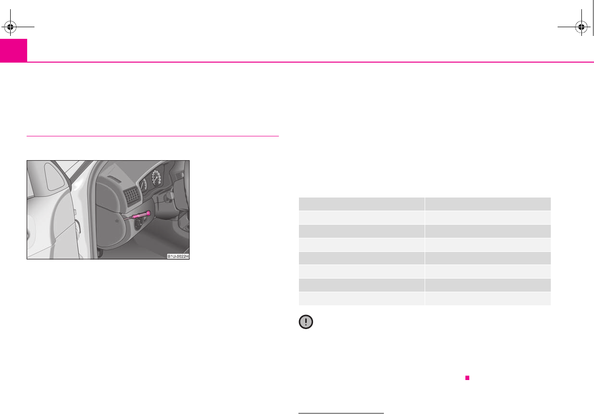
Fuses and light bulbs192
Fuses and light bulbs
Electric fuses
Replacing fuses
Defect fuses must be replaced.
Individual electrical circuits are protected by fuses. The fuses are located
on the left side of the dash panel behind the safety cover and under the
cover in the engine compartment on the left.
– Switch the ignition off and also the electrical component affected.
– Use a screwdriver to take off the fuse cover on the side of the dash
panel ⇒fig. 175 or the fuse cover in the engine compartment
⇒page 193.
– Find out which fuse belongs to the relevant component ⇒page 194,
“Fuse assignment in the dash panel”, ⇒page 193, “Fuse assignment
in engine compartment - version 1” or ⇒page 194, “Fuse assignment
in engine compartment - version 2”.
– Take the plastic clip out of its fixture in the fuse cover, insert it onto the
respective fuse and pull out this fuse.
– Defect fuses can be detected by their melted metal strips. Replace the
defect fuse by a new fuse of the same ampere number.
– Fit on the fuse cover again.
We recommend that you always have the small box of replacement fuses in your
vehicle. You can obtain replacement fuses from Škoda original accessories or from
a specialist garage7).
Colour coding of fuses
Caution
•Never attempt to “repair” fuses and also do not replace them with a fuse of a
higher amperage - risk of fire! This may also cause damage at another part of the
electrical system.
•Have the electrical system checked as quickly as possible by a specialist garage
if a newly inserted fuse blows again after a short time.
Fig. 175 Fuse cover: left side
of the dash panel
7) The small box with replacement fuses is part of the basic equipping of the vehicle in some
countries.
Colour Maximum amperage
light brown 5
brown 7,5
red 10
blue 15
yellow 20
white 25
green 30
s2g8.b.book Page 192 Tuesday, April 7, 2009 8:53 AM
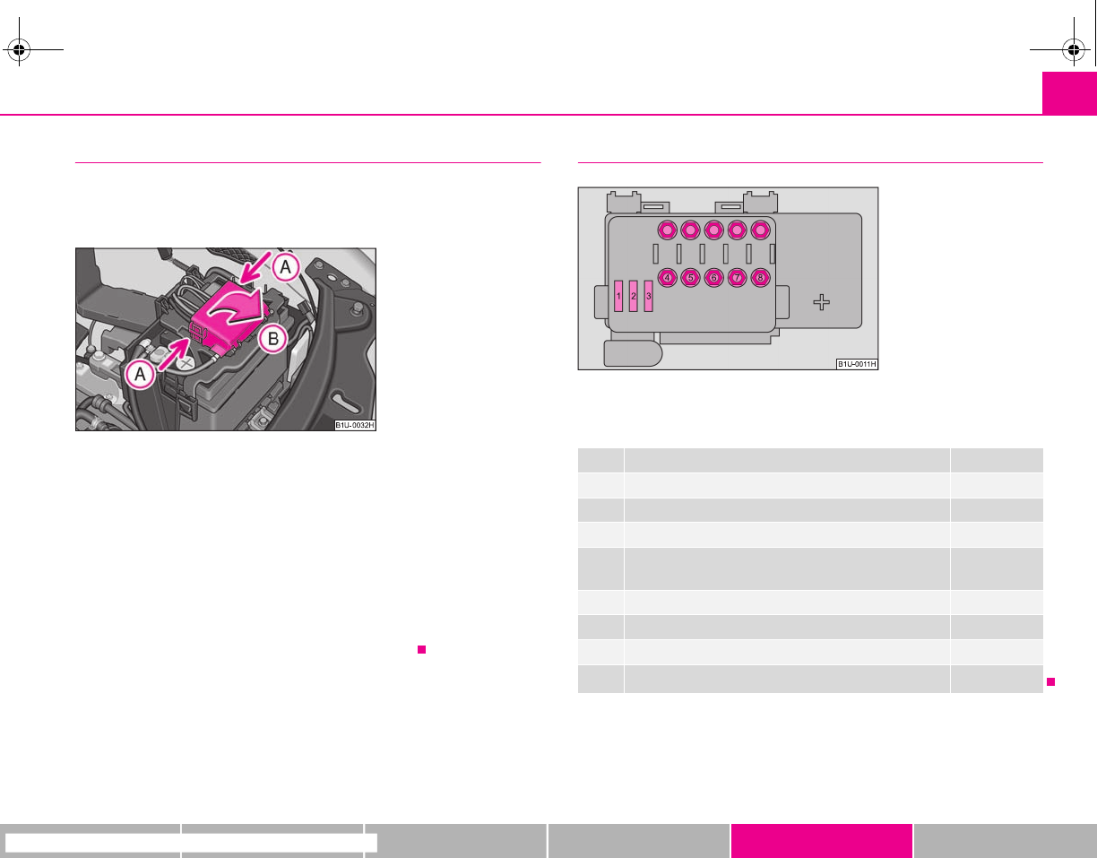
Fuses and light bulbs 193
riving Tips General Maintenance Breakdown assistance Technical Data
Fuse cover in engine compartment
The fuse box in the engine compartment exists in two different
versions. You can determine which version your vehicle is fitted with
after removing the fuse cover at the location of the fuses.
On some vehicles, the battery cover must be removed before removing
the fuse cover ⇒page 168.
Opening the cover
– Press together the interlocks of the fuse cover simultaneously in direc-
tion of arrow ⇒fig. 176 and fold down the cover in direction of
arrow .
Closing the cover
– Closing the cover takes place in the reverse order.
Fuse assignment in engine compartment - version 1
Certain electrical components are only standard on certain vehicle model versions
or only suppliable as optional equipment for certain models.
Fig. 176 Battery cover in the
engine compartment
A
A
A
B
No. Power consumer Amperes
1Pump for ABS 30
2Valves for ABS 30
3Radiator fan 1st stage 30
4Glow plugs for heating the coolant, relay for secondary
air pump
50
5Engine control unit 50
6Radiator fan 2nd stage 40
7Main fuse of the interior 110
8Dynamo 110 / 150a)
a) Depending on the engine type and equipment.
Fig. 177 Schematic repre-
sentation of fuse box in
engine compartment -
version 1
s2g8.b.book Page 193 Tuesday, April 7, 2009 8:53 AM
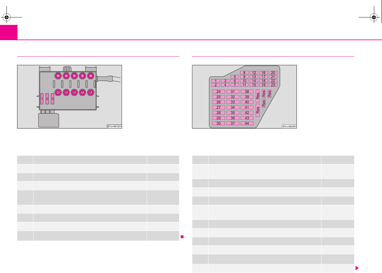
Fuses and light bulbs194
Fuse assignment in engine compartment - version 2
Certain electrical components are only standard on certain vehicle model versions
or only suppliable as optional equipment for certain models.
Fuse assignment in the dash panel
Certain electrical components are only standard on certain vehicle model versions
or only suppliable as optional equipment for certain models.
No. Power consumer Amperes
1Pump for ABS 30
2Valves for ABS 30
3Radiator fan 1st stage 30
4Glow plugs for heating the coolant, relay for secondary
air pump
50
5Engine control unit 50
6Radiator fan 2nd stage 40
7Main fuse of the interior 110
8Dynamo 110 / 150a)
a) Depending on the engine type and equipment.
Fig. 178 Schematic repre-
sentation of fuse box in
engine compartment -
version 2
No. Power consumer Amperes
1Heating of the exterior mirrors, relay for cigarette lighter,
power seats and washing nozzles 10
2Turn signal lights, Xenon headlight 10
3Lighting in storage compartment 5
4Licence plate light 5
5Seat heating, Climatronic, circulating air flap, exterior
mirror heater, cruise control system 7,5
6Central locking system 5
7Reversing light, sensors for parking aid 10
8Phone 5
9ABS, ESP 5
10 Ignition, S-contacta) 10
11 Instrument cluster 5
Fig. 179 Schematic repre-
sentation of the fuse carrier
in the dash panel
s2g8.b.book Page 194 Tuesday, April 7, 2009 8:53 AM
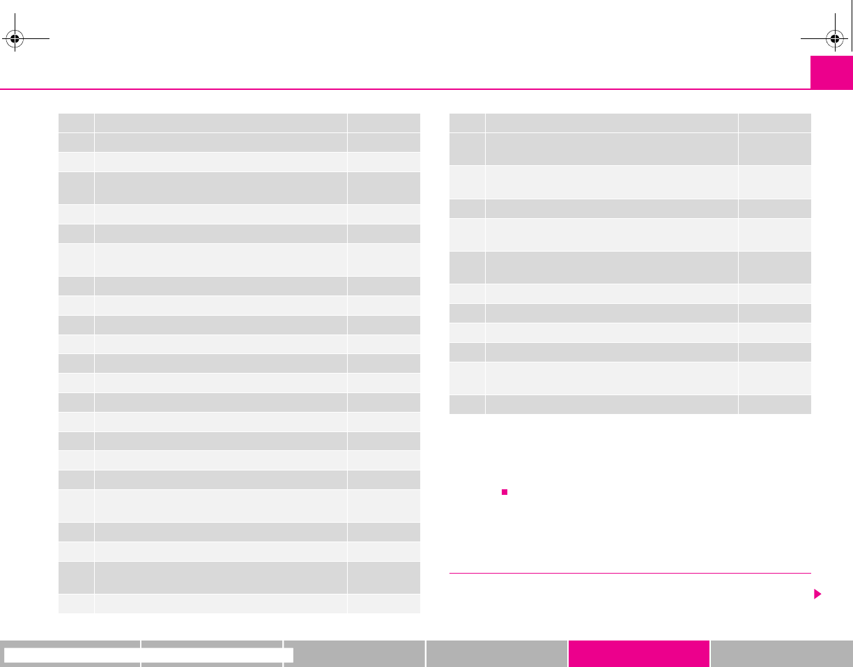
Fuses and light bulbs 195
riving Tips General Maintenance Breakdown assistance Technical Data
Electrically adjustable seats are protected by automatic circuit breakers, which
switch on again automatically after a few seconds after the overload has been
eliminated.
Bulbs
Changing bulbs
The relevant lamp must always be switched off before a light bulb is replaced.
12 Power supply of the self-diagnosis 7,5
13 Brake lights 10
14 Interior lighting, central locking system, interior lighting
(without central locking system) 10
15 Instrument cluster, steering angle sender, rear mirror 5
16 Air conditioning system 10
17 Heated windscreen washer nozzles
daylight driving lights
5
30
18 Right main beam 10
19 Left main beam 10
20 Right low beam, headlight range adjustment 15
21 Low beam on the left 15
22 Right parking light 5
23 Left parking light 5
24 Front window wiper, motor for wash pump 20
25 Air blower, air conditioning system, Climatronic 25
26 Rear window heater 25
27 Rear window wiper 15
28 Fuel pump 15
29 Control unit: Petrol engine
control unit: Diesel engine
15
10
30 Electric sliding/tilting roof 20
31 Not assigned
32 Petrol engine - injection valves
diesel engine - injection pump, control unit
10
30
33 Headlight cleaning system 20
No. Power consumer Amperes
34 Petrol engine: Control unit
diesel engine: Control unit
10
10
35 Trailer socket, power socket in the luggage compart-
ment 30
36 Fog lights 15
37 Petrol engine: Control unit
diesel engine: Control unit
20
5
38 Lighting of the luggage compartment, central locking
system, opening of the fuel filler flap, interior lighting 15
39 Hazard warning light system 15
40 Horn 20
41 Cigarette lighter 15
42 Radio, mobile phone 15
43 Petrol engine: Control unit
diesel engine: Control unit
10
10
44 Seat heaters 15
a) For power consumers, e.g. the radio, which can be operated with the ignition switched off as
long as the ignition key is not withdrawn.
No. Power consumer Amperes
s2g8.b.book Page 195 Tuesday, April 7, 2009 8:53 AM
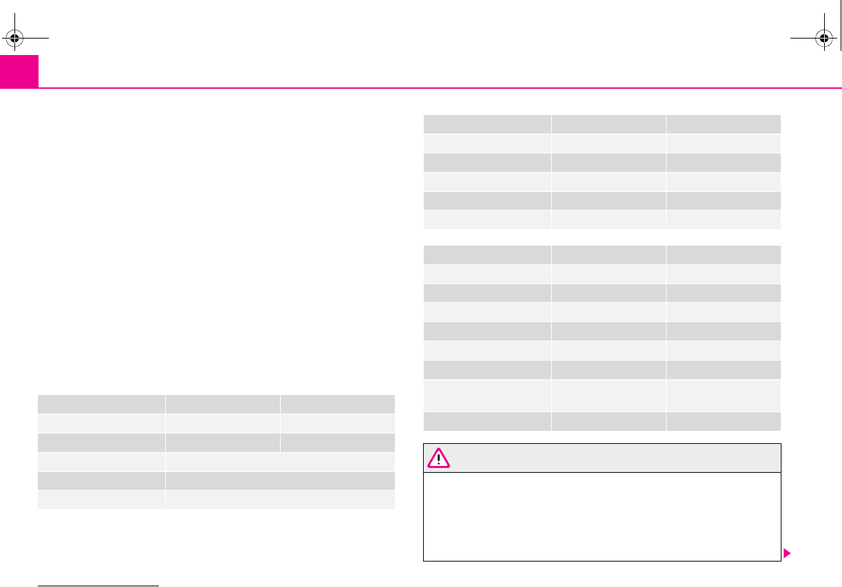
Fuses and light bulbs196
Defect light bulbs should only be replaced with light bulbs of the same type. The
designation is located on the light socket or the glass bulb.
Changing certain bulbs is not something which you can do yourself, but requires to
be done by a specialist. Other parts of the vehicle must be removed in order to
change the light bulbs. This applies, in particular, to bulbs which can only be
reached from the engine compartment.
We therefore recommend that you have any bulbs changed by a specialist garage
or, in exceptional cases, by calling on other professional assistance.
Please note that the engine compartment is a hazardous area ⇒page 160.
We recommend that you always have a small box of replacement bulbs in your
vehicle. You can obtain replacement bulbs from Škoda original accessories or from
a specialist garage8).
A stowage place for the bulbs is located in the box in the spare wheel*.
Fitted with a xenon headlight
Change of bulbs on vehicles with Xenon lights (low beam lights, parking lights and
main beam lights) should be undertaken by a specialist garage.
Bulb - Overview
WARNING
•Light bulbs H4 and H1 are pressurised and may burst when changing the
bulb - risk of injury!
•It is recommended to wear gloves and safety glasses when changing a
bulb.
•Gas discharge bulbs* (xenon bulbs) operate with a high voltage, profes-
sional knowledge is required - danger to life!
8) The small box with replacement bulbs is part of the basic equipping of the vehicle in some
countries.
Front headlight Halogen headlight Xenon headlight
Low beam light H4 D2S
Main beam light H4 H1
Parking lights W5W
Turn signals PY21W
Fog lights H3
Rear light unit Bulb (Octavia) Bulb (Combi)
Reversing light P21W P21W
Turn signals PY21W PY21W
Brake lights P21W P21/5W
Parking lights P21/4W P21/5W
Fog lights P21/4W P21W
Others Bulb (Octavia) Bulb (Combi)
Side turn signal lights WY5W WY5W
Licence plate light W5W W5W
3. Brake light W2, 3W LED
Interior lighting C10W C10W
Reading light W5W W5W
Luggage compartment light C5W C10W
Storage compartment light
- front passenger side
C3W C3W
Interior mirror light W2, 3W W2, 3W
s2g8.b.book Page 196 Tuesday, April 7, 2009 8:53 AM
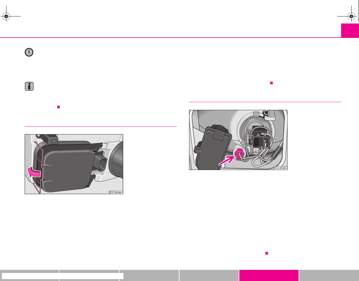
Fuses and light bulbs 197
riving Tips General Maintenance Breakdown assistance Technical Data
Caution
Do not take hold of the glass bulb with naked fingers (even the smallest amount of
dirt reduces the working life of the light bulb). Use a clean cloth, serviette or some-
thing similar.
Note
This Owner's Manual only describes the replacement of bulbs where it is assumed
that no major complications will arise. Other light bulbs should be replaced by your
specialist garage.
Main headlight with cover
Before changing the light bulb for the low beam and main beam light or
the light bulb for the parking light, remove the protective cover from the
rear part of the headlight.
Removing cover
– Switch the ignition and all lights off.
– Open the bonnet.
– Press off the circlip from the cover and fold it in the direction of arrow
⇒fig. 180.
– Remove the cover of the headlight by pulling towards the middle of
the vehicle.
Installation takes place in the reverse order.
Parking light at the front
Change the light bulb for the parking light
– Switch the ignition and all lights off.
– Open the bonnet.
– Remove the cover of the headlight.
– Pull the lamp holder with light bulb for the parking light out of the
headlight ⇒fig. 181.
– Take the faulty bulb out of the fixture and insert a new one.
– Insert the lamp holder with new light bulb into of the headlight.
– Insert the cover of the headlight.
Fig. 180 Removing cover
Fig. 181 Change the light
bulb for the parking light
s2g8.b.book Page 197 Tuesday, April 7, 2009 8:53 AM
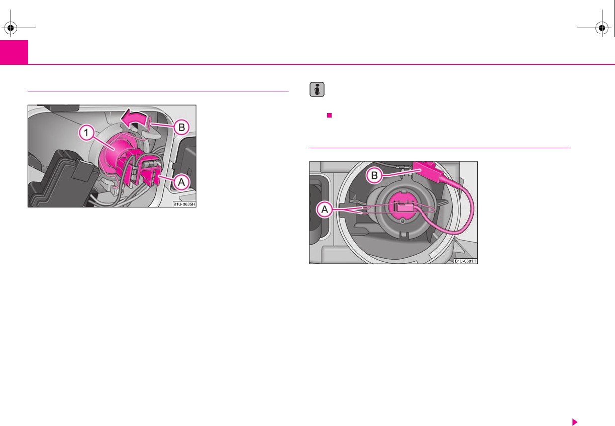
Fuses and light bulbs198
Main beam light and low beam light
Change light bulb for main beam light and low beam light
– Switch the ignition and all lights off.
– Open the bonnet.
– Remove the cover of the headlight.
– Hold the sprung wire clamp and disconnect the plug .
– Unhook the sprung wire clamp by pressing in direction of the light
bulb and fold it in direction of arrow.
– Remove the light bulb and insert the new light bulb in such a way
that the fixing lugs of the light bulb socket fit into the recesses at the
reflector.
– Fold the sprung wire clamp over the lamp holder and press it until it
locks into the holder.
–Plug in plug.
– Insert the cover of the headlight.
Note
Get the headlight setting checked by a specialist garage after replacing the light
bulb.
Fog lights*
Change light bulbs for fog lights
– Switch the ignition and all lights off.
– Open the bonnet.
– Turn the plastic cover of the headlight towards the middle of the
vehicle and remove it.
– Disconnect the plug connector .
– Unhook the sprung wire clamp out of the slots of the lamp housing
and fold it down.
– Remove the halogen lamp with cable. Insert the new halogen lamp in
such a way that the fixing lugs on the reflector lie in the corresponding
recesses in the light socket.
Fig. 182 Change light bulbs
for main beam lights and low
beam lights
A
B
A
A
A
B
A
1
Fig. 183 Change light bulbs
for fog lights
A
B
A
A
s2g8.b.book Page 198 Tuesday, April 7, 2009 8:53 AM
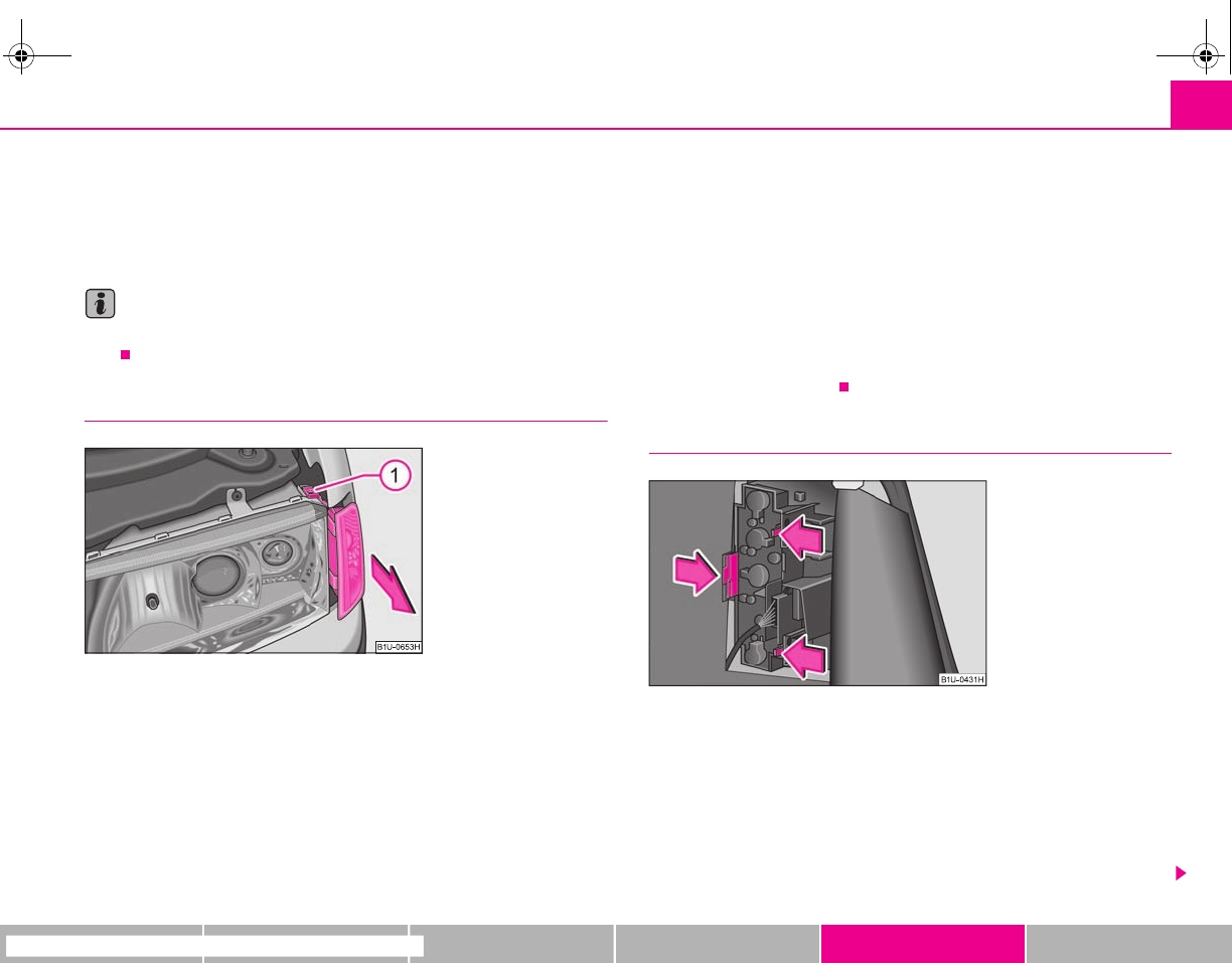
Fuses and light bulbs 199
riving Tips General Maintenance Breakdown assistance Technical Data
– Close the sprung wire clamp over the light socket. Press together the
sprung wire clamp and lock together again.
–Plug in plug.
– Insert the plastic cover.
Note
Get the headlight setting checked by a specialist garage after replacing the light
bulb.
Turn signal light at the front
Changing light bulb for turn signal light (at the front)
– Switch the ignition and all lights off.
– Open the bonnet.
– Unscrew the screw .
– Push the lamp out in direction of arrow ⇒fig. 184.
– Turn the holder with the light bulb to the left and pull it out.
– Press the defective light bulb into the socket, turn to the left and
remove.
– Press a new light bulb into the socket and turn the light bulb to the
right as far as the stop.
– Insert the holder with the light bulb into the housing of the turn signal
light and turn it to the right up to the stop.
– Push the housing of the turn signal light back in such a way that the
guide lugs lock into the circlips of the main headlight.
– Screw in the screw .
Light unit (Octavia)
Changing light bulbs in the lamp holder
– Switch the ignition and all lights off.
– Open the boot lid.
– Raise the floor covering.
– Press off the catches in the direction of arrow ⇒fig. 185 and take out
the lamp holder.
Fig. 184 Removing the light
bulb for the turn signal light
A
1
A
1
Fig. 185 Luggage compart-
ment: Light bulb holder
s2g8.b.book Page 199 Tuesday, April 7, 2009 8:53 AM
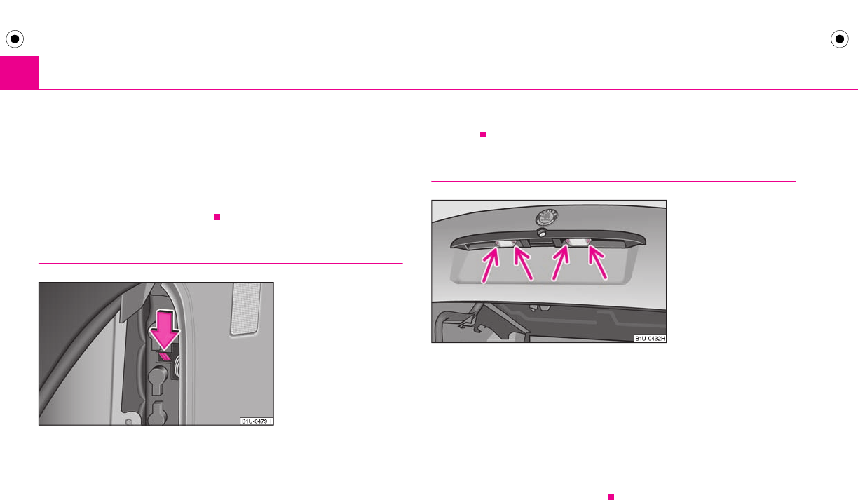
Fuses and light bulbs200
– Press the defective light bulb into the socket, turn to the left and
remove.
– Insert the new light bulb and turn it to the right up to the stop.
– Insert the light bulb holder again, the flexible tongues must lock in
place.
– Push the cover back into place.
Rear light unit (Combi)
Changing light bulbs in the lamp holder
– Switch the ignition and all lights off.
– Open the boot lid.
– Open the relevant storage compartment in the luggage compartment.
– Press off the flexible tongue in direction of arrow ⇒fig. 186 and
remove the lamp holder.
– Press the defective light bulb into the socket, turn to the left and
remove.
– Insert the new light bulb and turn it to the right up to the stop.
– Insert the light bulb holder again, the plastic tongue must lock in
place.
Licence plate light
Changing light bulbs of licence plate light
– Switch the ignition and all lights off.
– Open the boot lid and unscrew the light glass.
– Take the faulty bulb out of the holder and insert a new one.
– Insert the glass cover of the light again and press it down to the stop -
ensure that the sealing rubber is correctly seated.
– Screw on the light glass slightly.
Fig. 186 Luggage compart-
ment: Light bulb holder
Fig. 187 Licence plate light:
Replacing light bulb
s2g8.b.book Page 200 Tuesday, April 7, 2009 8:53 AM
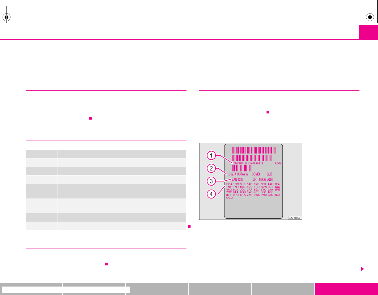
Technical Data 201
riving Tips General Maintenance Breakdown assistance Technical Data
Technical Data
Technical Data
General information
The details given in the official vehicle registration documents always take prece-
dence over the details in the Owner's Manual. Please refer to the official vehicle
registration documents or consult a specialist garage concerning the engine with
which your vehicle is equipped.
Used abbreviations
Performances
The listed performance values were determined without performance-reducing
equipment, e.g. air conditioning system.
Weight
The loading capacity is reduced in line with the range of the special equipment. The
unloaden weight contains a fuel tank topped up to 90%. A driver with a weight of
75 kg is also included in the value.
Identification details
Vehicle data sticker
The vehicle data sticker ⇒fig. 188 is located on the floor of the luggage compart-
ment and is also stated in the Service schedule.
The vehicle data sticker contains the following data:
Vehicle identification number (VIN)
Vehicle type
Abbreviation Importance
kW Kilowatt, measuring unit for the engine output
rpm Engine revolutions per minute
Nm Newton meter, measuring unit for the engine torque
CO2 in g/km discharged quantity of carbon dioxide in grams per driven kilom-
eter
RON Research octane number, measuring unit for the knocking resist-
ance of petrol
M5 5-speed manual gearbox
PD Unit injector engine
Fig. 188 Vehicle data sticker
A
1
A
2
s2g8.b.book Page 201 Tuesday, April 7, 2009 8:53 AM

Technical Data202
Gearbox code, paint number, interior equipment number, engine output,
engine code
Partial description of the vehicle
Vehicle identification number (VIN)
The vehicle identification number - VIN (vehicle body number) is stamped into the
engine compartment on the right hand shock absorber dome. This number is also
located on a sign on the lower left hand edge below the windscreen (together with
a VIN bar code).
Engine number
The engine number is stamped into the engine block.
Type plate (production plate)
The type plate is located in the engine compartment at the front on the left hand
shock absorber dome.
Homologation sign
The homologation sign is located on the lock carrier. Vehicles for certain countries
do not have an homologation sign.
Sticker on inside of fuel filler flap
The sticker is affixed to the inside of the fuel filler flap. They contain the following
data:
•the prescribed type of fuel;
•tyre size;
•Tyre pressure.
Fuel consumption according to the regulations
(99/100/EU)
Depending on the range of the special equipment, style of driving, traffic situation,
weather influences and vehicle condition, the consumption values which in prac-
tice result when using the vehicle can deviate from the indicated values.
Urban traffic
The consumption measurement in urban traffic begins with starting of the cold
engine. Afterwards the normal urban traffic is simulated.
Non-urban traffic
For the consumption measurement in non-urban traffic the vehicle, as in daily
motoring, is accelerated and braked several times in all gears. The vehicle speed
changes within the range from 0 to 120 km/h.
Combined traffic
The consumption value in the combined traffic consists of 37% from the value for
the urban traffic and of 63% from the value for the non-urban traffic.
A
3
A
4
s2g8.b.book Page 202 Tuesday, April 7, 2009 8:53 AM

Technical Data 203
riving Tips General Maintenance Breakdown assistance Technical Data
Dimensions
Dimensions (mm)
OCTAVIA COMBI
Length 4507 4513
Width 1731 1731
Width including exterior mirror 1984 1984
Height 1431/1455a)
a) The value corresponds to the status with rough road package.
1457/1481a)
Wheel base 2512 2512
Track gauge front / rear 1513/1494 1513/1494
Clearance 134 134
s2g8.b.book Page 203 Tuesday, April 7, 2009 8:53 AM

Technical Data204
1.4 ltr./55 kW - EU4
Engine
Performances
Fuel consumption (in ltr./100°km) and CO2 emission (in g/km)
Power output kW per rpm 55/5000
Maximum torque Nm per rpm 126/3800
Number of cylinders 4
Displacement cm31389
Fuel - unleaded petrol min. RON 95
OCTAVIA - M5 COMBI - M5
Maximum speed km/h 171 171
Acceleration 0 - 100 km/h s15,3 15,5
OCTAVIA - M5 COMBI - M5
Urban consumption 9,1 9,1
Non-urban consumption 5,4 5,4
Consumption - combination 6,8 6,8
CO2 emission - combination 163 163
s2g8.b.book Page 204 Tuesday, April 7, 2009 8:53 AM

Technical Data 205
riving Tips General Maintenance Breakdown assistance Technical Data
Capacities (in liter)
Weight (in kg)
Fuel tank capacity/of which spare 55/7
Reservoir for windscreen washer system/ with headlight cleaning system 3/5,5
Engine oila)
a) Oil capacity with oil filter change. Inspect oil level according to filling - see Owner's Manual.
3,2
Cooling system of the vehicle 5,5
OCTAVIA - M5 COMBI - M5
Permissible gross weight 1750 1770
Unloaden weight ready for work 1230 1245
Loading capacity 520 525
Loading capacity when using the TLC 470 475
Permissible front axle load 1000 1000
Permissible rear axle load 990 1000
Permissible trailer loads, trailer braked 850a)/850b)
a) For uphills up to 12%.
b) Only country specific up to 8% uphill.
850a)/850b)
Permissible trailer loads, trailer unbraked 500 500
s2g8.b.book Page 205 Tuesday, April 7, 2009 8:53 AM

Technical Data206
1.6 ltr./75 kW - EU4/EU2 DDK
Engine
Performances
Fuel consumption (in ltr./100°km) and CO2 emission (in g/km)
Power output kW per rpm 75/5600
Maximum torque Nm per rpm 148/3800
Number of cylinders 4
Displacement cm31595
Fuel - unleaded petrol min. RON 95
OCTAVIA - M5 COMBI - M5
Maximum speed km/h 190 190
Acceleration 0 - 100 km/h s11,8 11,9
OCTAVIA - M5 COMBI - M5
Urban consumption 9,9 9,9
Non-urban consumption 5,5 5,5
Consumption - combination 7,1 7,1
CO2 emission - combination 169 169
s2g8.b.book Page 206 Tuesday, April 7, 2009 8:53 AM

Technical Data 207
riving Tips General Maintenance Breakdown assistance Technical Data
Capacities (in liter)
Weight (in kg)
Fuel tank capacity/of which spare 55/7
Reservoir for windscreen washer system/ with headlight cleaning system 3/5,5
Engine oila)
a) Oil capacity with oil filter change. Inspect oil level according to filling - see Owner's Manual.
4,5
Cooling system of the vehicle 7,0
OCTAVIA - M5 COMBI - M5
Permissible gross weight 1790 1805
Unloaden weight ready for work 1260 1275
Loading capacity 530 530
Loading capacity when using the TLC 470 470
Permissible front axle load 1000 1000
Permissible rear axle load 990 1000
Permissible trailer loads, trailer braked 1200a)/1400b)
a) For uphills up to 12%.
b) Only country specific up to 8% uphill.
1200a)/1400b)
Permissible trailer loads, trailer unbraked 500 500
s2g8.b.book Page 207 Tuesday, April 7, 2009 8:53 AM
Technical Data208
1.8 ltr./110 kW - EU4/EU3D
Engine
Performances
Fuel consumption (in ltr./100°km) and CO2 emission (in g/km)
Power output kW per rpm 110/5700
Maximum torque Nm per rpm 210/1750-4600
Number of cylinders 4
Displacement cm31781
Fuel - unleaded petrol min. RON 95
OCTAVIA - M5 COMBI - M5
Maximum speed km/h 219 219
Acceleration 0 - 100 km/h s8,4 8,5
OCTAVIA - M5 COMBI - M5
EU4 EU3D EU4 EU3D
Urban consumption 10,7 10,9 10,7 10,9
Non-urban consumption 6,2 6,2 6,2 6,3
Consumption - combination 7,9 7,9 7,9 8,0
CO2 emission - combination 189 190 189 192
s2g8.b.book Page 208 Tuesday, April 7, 2009 8:53 AM

Technical Data 209
riving Tips General Maintenance Breakdown assistance Technical Data
Capacities (in liter)
Weight (in kg)
Fuel tank capacity/of which spare 55/7
Reservoir for windscreen washer system/ with headlight cleaning system 3/5,5
Engine oila)
a) Oil capacity with oil filter change. Inspect oil level according to filling - see Owner's Manual.
4,5
Cooling system of the vehicle 6,8
OCTAVIA - M5 COMBI - M5
Permissible gross weight 1845 1865
Unloaden weight ready for work 1315 1330
Loading capacity 530 535
Loading capacity when using the TLC 470 475
Permissible front axle load 1000 1000
Permissible rear axle load 990 1000
Permissible trailer loads, trailer braked 1300a)/1500b)
a) For uphills up to 12%.
b) Only country specific up to 8% uphill.
1300a)/1500b)
Permissible trailer loads, trailer unbraked 500 500
s2g8.b.book Page 209 Tuesday, April 7, 2009 8:53 AM
Technical Data210
1.9 ltr./66 kW TDI - EU3
Engine
Performances
Fuel consumption (in ltr./100°km) and CO2 emission (in g/km)
Power output kW per rpm 66/4000
Maximum torque Nm per rpm 210/1900
Number of cylinders 4
Displacement cm31896
Fuel Diesel
OCTAVIA - M5 COMBI - M5
Maximum speed km/h 182 182
Acceleration 0 - 100 km/h s13,0 13,3
OCTAVIA - M5 COMBI - M5
Urban consumption 6,6 6,6
Non-urban consumption 4,2 4,2
Consumption - combination 5,0 5,0
CO2 emission - combination 135 135
s2g8.b.book Page 210 Tuesday, April 7, 2009 8:53 AM

Technical Data 211
riving Tips General Maintenance Breakdown assistance Technical Data
Capacities (in liter)
Weight (in kg)
Fuel tank capacity/of which spare 55/7
Reservoir for windscreen washer system/ with headlight cleaning sys-
tem
3/5,5
Engine oila)
a) Oil capacity with oil filter change. Inspect oil level according to filling - see Owner's Manual.
3,8
Cooling system of the vehicle 6,8
OCTAVIA - M5 COMBI - M5
Permissible gross weight 1855 1875
Unloaden weight ready for work 1325 1340
Loading capacity 530 535
Loading capacity when using the TLC 470 475
Permissible front axle load 1000 1000
Permissible rear axle load 990 1000
Permissible trailer loads, trailer braked 1300a)/1500b)
a) For uphills up to 12%.
b) Only country specific up to 8% uphill.
1300a)/1500b)
Permissible trailer loads, trailer unbraked 500 500
s2g8.b.book Page 211 Tuesday, April 7, 2009 8:53 AM

Technical Data212
1.9 ltr./74 kW TDI PD - EU4
Engine
Performances
Fuel consumption (in ltr./100°km) and CO2 emission (in g/km)
Power output kW per rpm 74/4000
Maximum torque Nm per rpm 240/1800
Number of cylinders 4
Displacement cm31896
Fuel Diesel
OCTAVIA - M5 COMBI - M5
Maximum speed km/h 189 189
Acceleration 0 - 100 km/h s11,8 11,9
OCTAVIA - M5 COMBI - M5
Urban consumption 6,5 6,5
Non-urban consumption 4,3 4,3
Consumption - combination 5,1 5,1
CO2 emission - combination 135 135
s2g8.b.book Page 212 Tuesday, April 7, 2009 8:53 AM

Technical Data 213
riving Tips General Maintenance Breakdown assistance Technical Data
Capacities (in liter)
Weight (in kg)
Fuel tank capacity/of which spare 55/7
Reservoir for windscreen washer system/ with headlight cleaning system 3/5,5
Engine oila)
a) Oil capacity with oil filter change. Inspect oil level according to filling - see Owner's Manual.
4,3
Cooling system of the vehicle 6,8
OCTAVIA - M5 COMBI - M5
Permissible gross weight 1855 1875
Unloaden weight ready for work 1325 1340
Loading capacity 530 535
Loading capacity when using the TLC 470 475
Permissible front axle load 1000 1000
Permissible rear axle load 990 1000
Permissible trailer loads, trailer braked 1300a)/1500b)
a) For uphills up to 12%.
b) Only country specific up to 8% uphill.
1300a)/1500b)
Permissible trailer loads, trailer unbraked 500 500
s2g8.b.book Page 213 Tuesday, April 7, 2009 8:53 AM
Technical Data214
Octavia - Vehicles of the group N1
Octavia Combi - Vehicles of the group N1
Engine 1.4 ltr./55 kW - EU4 1.6 ltr./75 kW - EU4 1.8 ltr./110 kW - EU4 1.9 ltr./74 kW TDI PD - EU4
Permissible gross weight 1690 1720 1775 1785
Unloaden weight ready for work 1230 1260 1315 1325
Loading capacity 460 460 460 460
Loading capacity when using the TLC 410 400 400 400
Engine 1.4 ltr./55 kW - EU4 1.6 ltr./75 kW - EU4 1.8 ltr./110 kW - EU4 1.9 ltr./74 kW TDI PD - EU4
Permissible gross weight 1705 1735 1790 1800
Unloaden weight ready for work 1245 1275 1330 1340
Loading capacity 460 460 460 460
Loading capacity when using the TLC 410 400 400 400
s2g8.b.book Page 214 Tuesday, April 7, 2009 8:53 AM

Index 215
riving Tips General Maintenance Breakdown assistance Technical Data
Index
A
Abroad . . . . . . . . . . . . . . . . . . . . . . . . . . . . . . . . . . . . . 142
ABS . . . . . . . . . . . . . . . . . . . . . . . . . . . . . . . . . . . . . . . . . 135
Warning light . . . . . . . . . . . . . . . . . . . . . . . . . . . . . 32
Accessories . . . . . . . . . . . . . . . . . . . . . . . . . . . . . . . . . 179
Adjusting seats . . . . . . . . . . . . . . . . . . . . . . . . . . . 60, 104
electrically . . . . . . . . . . . . . . . . . . . . . . . . . . . . . . . . 61
Adjusting the steering wheel . . . . . . . . . . . . . . . . . . . 93
Air conditioning system . . . . . . . . . . . . . . . . . . . . . . . 85
Recirculated air mode . . . . . . . . . . . . . . . . . . . . . 88
Airbag . . . . . . . . . . . . . . . . . . . . . . . . . . . . . . . . . . . . . . 115
Deployment . . . . . . . . . . . . . . . . . . . . . . . . . . . . . 116
Front airbag . . . . . . . . . . . . . . . . . . . . . . . . . . . . . 116
Side airbag . . . . . . . . . . . . . . . . . . . . . . . . . . . . . . 119
Warning light . . . . . . . . . . . . . . . . . . . . . . . . . . . . . 30
Airbag system . . . . . . . . . . . . . . . . . . . . . . . . . . . . . . . 115
Warning light . . . . . . . . . . . . . . . . . . . . . . . . . . . . . 30
Airbags . . . . . . . . . . . . . . . . . . . . . . . . . . . . . . . . . . . . . 115
Alarm . . . . . . . . . . . . . . . . . . . . . . . . . . . . . . . . . . . . . . . . 43
Alternator
Warning light . . . . . . . . . . . . . . . . . . . . . . . . . . . . . 34
Antilock brake system . . . . . . . . . . . . . . . . . . . . . . . . 135
Antilock brake system (ABS)
Warning light . . . . . . . . . . . . . . . . . . . . . . . . . . . . . 32
Anti-theft alarm system . . . . . . . . . . . . . . . . . . . . . . . 43
Ashtray . . . . . . . . . . . . . . . . . . . . . . . . . . . . . . . . . . . . . . 77
Auto Check Control . . . . . . . . . . . . . . . . . . . . . . . . . . . 25
Auto Computer . . . . . . . . . . . . . . . . . . . . . . . . . . . . . . 19
Automatic seat adjustment . . . . . . . . . . . . . . . . . . . . 62
Automatic vehicle wash systems . . . . . . . . . . . . . . 148
Automatic wiper/washer system . . . . . . . . . . . . . . . 56
Avoiding damage to your vehicle . . . . . . . . . . . . . 143
B
Battery . . . . . . . . . . . . . . . . . . . . . . . . . . . . . . . . . . 34, 168
change . . . . . . . . . . . . . . . . . . . . . . . . . . . . . . . . . . 171
Charge . . . . . . . . . . . . . . . . . . . . . . . . . . . . . . . . . . 170
Inspecting the electrolyte level . . . . . . . . . . . . 170
Operation in winter . . . . . . . . . . . . . . . . . . . . . . 170
Before setting off . . . . . . . . . . . . . . . . . . . . . . . . . . . . 103
Belt
Warning light . . . . . . . . . . . . . . . . . . . . . . . . . . . . . 34
Belt tensioners . . . . . . . . . . . . . . . . . . . . . . . . . . . . . . 113
Belts . . . . . . . . . . . . . . . . . . . . . . . . . . . . . . . . . . . . . . . . 108
Bonnet . . . . . . . . . . . . . . . . . . . . . . . . . . . . . . . . . . 14, 159
Boot lid . . . . . . . . . . . . . . . . . . . . . . . . . . . . . . . . . . . . . . 41
Brake
Handbrake . . . . . . . . . . . . . . . . . . . . . . . . . . . . . . . 97
Warning light . . . . . . . . . . . . . . . . . . . . . . . . . . . . . 34
Brake Assist . . . . . . . . . . . . . . . . . . . . . . . . . . . . . . . . . 135
Brake booster . . . . . . . . . . . . . . . . . . . . . . . . . . . . . . . 134
Brake fluid . . . . . . . . . . . . . . . . . . . . . . . . . . . . . . . . . . 167
Brake pads
Warning light . . . . . . . . . . . . . . . . . . . . . . . . . . . . . 31
Brakes . . . . . . . . . . . . . . . . . . . . . . . . . . . . . . . . . . . . . . 133
Bulbs
Warning light . . . . . . . . . . . . . . . . . . . . . . . . . . . . . 29
Button for the central locking system . . . . . . . . . . . 40
Buttons on the driver's door
Power windows . . . . . . . . . . . . . . . . . . . . . . . . . . . 44
C
Car state . . . . . . . . . . . . . . . . . . . . . . . . . . . . . . . . . . . . . 25
Catalytic converter . . . . . . . . . . . . . . . . . . . . . . . . . . 138
Central locking system . . . . . . . . . . . . . . . . . . . . . . . . 38
lock . . . . . . . . . . . . . . . . . . . . . . . . . . . . . . . . . . . . . . 39
unlock . . . . . . . . . . . . . . . . . . . . . . . . . . . . . . . . . . . 39
Changing a wheel . . . . . . . . . . . . . . . . . . . . . . . . . . . 183
Changing bulbs . . . . . . . . . . . . . . . . . . . . . . . . . . . . . 195
Changing the engine oil . . . . . . . . . . . . . . . . . . . . . . 164
Changing wheels around . . . . . . . . . . . . . . . . . . . . . 175
Charging the battery . . . . . . . . . . . . . . . . . . . . . . . . . 170
Warning light . . . . . . . . . . . . . . . . . . . . . . . . . . . . . 34
Check engine oil level . . . . . . . . . . . . . . . . . . . . . . . . 163
Child safety . . . . . . . . . . . . . . . . . . . . . . . . . . . . . . . . . 123
Side airbag . . . . . . . . . . . . . . . . . . . . . . . . . . . . . . 125
Child safety lock . . . . . . . . . . . . . . . . . . . . . . . . . . . . . . 37
Child safety seat
on the front passenger seat . . . . . . . . . . . . . . . 124
Safety information . . . . . . . . . . . . . . . . . . . . . . . 123
s2g8.b.book Page 215 Tuesday, April 7, 2009 8:53 AM

Index216
Child seat . . . . . . . . . . . . . . . . . . . . . . . . . . . . . . . . . . . 126
Classification into groups . . . . . . . . . . . . . . . . . 126
ISOFIX system . . . . . . . . . . . . . . . . . . . . . . . . . . . . 129
Use of child safety seats . . . . . . . . . . . . . . . . . . 126
Children and safety . . . . . . . . . . . . . . . . . . . . . . . . . . 123
Chrome parts . . . . . . . . . . . . . . . . . . . . . . . . . . . . . . . 149
Cigarette lighter . . . . . . . . . . . . . . . . . . . . . . . . . . . . . . 78
Cleaning . . . . . . . . . . . . . . . . . . . . . . . . . . . . . . . . . . . . 147
Climatronic
Defrosting windows . . . . . . . . . . . . . . . . . . . . . . . 91
Recirculated air mode . . . . . . . . . . . . . . . . . . . . . 91
Setting temperature . . . . . . . . . . . . . . . . . . . . . . . 92
Climatronic (automatic air conditioning) . . . . . . . 89
Clock . . . . . . . . . . . . . . . . . . . . . . . . . . . . . . . . . . . . . . . . 19
Clothes hooks . . . . . . . . . . . . . . . . . . . . . . . . . . . . . . . . 82
Cockpit
General view . . . . . . . . . . . . . . . . . . . . . . . . . . . . . . . 9
Compartments . . . . . . . . . . . . . . . . . . . . . . . . . . . . . . . 79
Computer . . . . . . . . . . . . . . . . . . . . . . . . . . . . . . . . . . . . 19
Convenience operation . . . . . . . . . . . . . . . . . . . . . . . 45
Converting/masking over headlights . . . . . . . . . . 142
Coolant . . . . . . . . . . . . . . . . . . . . . . . . . . . . . . . . . . . . . 165
replenishing . . . . . . . . . . . . . . . . . . . . . . . . . . . . . 166
Warning light . . . . . . . . . . . . . . . . . . . . . . . . . . . . . 30
Coolant level
Warning light . . . . . . . . . . . . . . . . . . . . . . . . . . . . . 30
Coolant quantity
Warning light . . . . . . . . . . . . . . . . . . . . . . . . . . . . . 30
Coolant temperature gauge . . . . . . . . . . . . . . . . . . . 16
Coolant temperature/coolant level
Warning light . . . . . . . . . . . . . . . . . . . . . . . . . . . . . 30
Correct seated position . . . . . . . . . . . . . . . . . . . . . . 104
Counter for distance driven . . . . . . . . . . . . . . . . . . . . 18
Cruise control system . . . . . . . . . . . . . . . . . . . . . . . . . . 98
Cup holder
front . . . . . . . . . . . . . . . . . . . . . . . . . . . . . . . . . . . . . . 76
D
Deactivating
an airbag . . . . . . . . . . . . . . . . . . . . . . . . . . . . . . . . 120
Deactivating an airbag . . . . . . . . . . . . . . . . . . . . . . . 120
Defrosting rear window . . . . . . . . . . . . . . . . . . . . . . . . 55
De-icing the windows . . . . . . . . . . . . . . . . . . . . . . . 150
Detachable towing device . . . . . . . . . . . . . . . . . . . 146
Diesel . . . . . . . . . . . . . . . . . . . . . . . . . . . . . . . . . . . . . . 155
Diesel engines
Starting the engine . . . . . . . . . . . . . . . . . . . . . . . . . 95
Digital clock . . . . . . . . . . . . . . . . . . . . . . . . . . . . . . . . . . 19
Direction indicators . . . . . . . . . . . . . . . . . . . . . . . . . . . 52
Warning light . . . . . . . . . . . . . . . . . . . . . . . . . . . . . . 28
Display . . . . . . . . . . . . . . . . . . . . . . . . . . . . . . . . . . . . . . . 23
Distance driven . . . . . . . . . . . . . . . . . . . . . . . . . . . . . . . 18
Door
Child safety lock . . . . . . . . . . . . . . . . . . . . . . . . . . . 37
Driving economically . . . . . . . . . . . . . . . . . . . . . . . . 138
E
EDL . . . . . . . . . . . . . . . . . . . . . . . . . . . . . . . . . . . . . . . . 132
Electric sliding/tilting roof . . . . . . . . . . . . . . . . . . . . . . 46
Electrically adjustable exterior mirror . . . . . . . . . . . 58
Electronic Differential Lock . . . . . . . . . . . . . . . . . . . 132
Electronic immobiliser . . . . . . . . . . . . . . . . . . . . . 29, 36
Warning light . . . . . . . . . . . . . . . . . . . . . . . . . . . . . . 29
Electronic stability programme . . . . . . . . . . . . . . . . 131
Electronic stability programme (ESP)
Warning light . . . . . . . . . . . . . . . . . . . . . . . . . . . . . 33
Emergency wheel . . . . . . . . . . . . . . . . . . . . . . . . . . . . 183
Engine
starting . . . . . . . . . . . . . . . . . . . . . . . . . . . . . . . . . . . 94
switching off . . . . . . . . . . . . . . . . . . . . . . . . . . . . . . 96
Engine compartment
Safety information . . . . . . . . . . . . . . . . . . . . . . . . 160
Engine electronics
Warning light . . . . . . . . . . . . . . . . . . . . . . . . . . . . . 29
Engine oil . . . . . . . . . . . . . . . . . . . . . . . . . . . . . . . . . . . 162
Changing . . . . . . . . . . . . . . . . . . . . . . . . . . . . . . . . 164
changing . . . . . . . . . . . . . . . . . . . . . . . . . . . . . . . . 164
check . . . . . . . . . . . . . . . . . . . . . . . . . . . . . . . . . . . . 163
replenishing . . . . . . . . . . . . . . . . . . . . . . . . . . . . . 163
Warning light . . . . . . . . . . . . . . . . . . . . . . . . . . . . . 31
Engine revolutions counter . . . . . . . . . . . . . . . . . . . . 16
Environment . . . . . . . . . . . . . . . . . . . . . . . . . . . . . . . . 138
Environmental compatibility . . . . . . . . . . . . . 138, 142
ESP . . . . . . . . . . . . . . . . . . . . . . . . . . . . . . . . . . . . . . . . . 131
Warning light . . . . . . . . . . . . . . . . . . . . . . . . . . . . . 33
Exhaust gas
Warning light . . . . . . . . . . . . . . . . . . . . . . . . . . . . . 29
Exhaust gas inspection
Warning light . . . . . . . . . . . . . . . . . . . . . . . . . . . . . 29
Explanations . . . . . . . . . . . . . . . . . . . . . . . . . . . . . . . . . . . 6
Exterior mirror . . . . . . . . . . . . . . . . . . . . . . . . . . . . . . . . 58
Exterior mirror heater . . . . . . . . . . . . . . . . . . . . . . . . . 58
F
First-aid box . . . . . . . . . . . . . . . . . . . . . . . . . . . . . . . . . 181
s2g8.b.book Page 216 Tuesday, April 7, 2009 8:53 AM

Index 217
riving Tips General Maintenance Breakdown assistance Technical Data
Fixing net
Combi . . . . . . . . . . . . . . . . . . . . . . . . . . . . . . . . . . . . 70
Octavia . . . . . . . . . . . . . . . . . . . . . . . . . . . . . . . . . . . 69
Fog lights . . . . . . . . . . . . . . . . . . . . . . . . . . . . . . . . . . . . . 50
Warning light . . . . . . . . . . . . . . . . . . . . . . . . . . . . . . 29
Front airbag . . . . . . . . . . . . . . . . . . . . . . . . . . . . . . . . . 116
Front armrest . . . . . . . . . . . . . . . . . . . . . . . . . . . . . . . . . 81
Fuel . . . . . . . . . . . . . . . . . . . . . . . . . . . . . . . . . . . . . . . . 155
Diesel fuel . . . . . . . . . . . . . . . . . . . . . . . . . . . . . . . 155
Fuel gauge . . . . . . . . . . . . . . . . . . . . . . . . . . . . . . . . 17
Petrol . . . . . . . . . . . . . . . . . . . . . . . . . . . . . . . . . . . 155
Fuel consumption . . . . . . . . . . . . . . . . . . . . . . . . . . . 138
Saving energy . . . . . . . . . . . . . . . . . . . . . . . . . . . 138
Fuel gauge . . . . . . . . . . . . . . . . . . . . . . . . . . . . . . . . . . . . 17
Fuel reserve
Warning light . . . . . . . . . . . . . . . . . . . . . . . . . . . . . . 31
Full wheel trim . . . . . . . . . . . . . . . . . . . . . . . . . . . . . . 185
Fuses . . . . . . . . . . . . . . . . . . . . . . . . . . . . . . . . . . . . . . . 192
G
Gauges . . . . . . . . . . . . . . . . . . . . . . . . . . . . . . . . . . . . . . . 16
Gearbox
mechanical . . . . . . . . . . . . . . . . . . . . . . . . . . . . . . . . 96
General view
Cockpit . . . . . . . . . . . . . . . . . . . . . . . . . . . . . . . . . . . . 9
Glass roof . . . . . . . . . . . . . . . . . . . . . . . . . . . . . . . . . . . . . 46
Glow plug system . . . . . . . . . . . . . . . . . . . . . . . . . . . . . 95
Warning light . . . . . . . . . . . . . . . . . . . . . . . . . . . . . . 30
H
Handbrake . . . . . . . . . . . . . . . . . . . . . . . . . . . . . . . . . . . 97
Hazard warning light system . . . . . . . . . . . . . . . . . . . 52
Warning light . . . . . . . . . . . . . . . . . . . . . . . . . . . . . . 28
Head restraint . . . . . . . . . . . . . . . . . . . . . . . . . . . . . . . . 64
Headlight flasher . . . . . . . . . . . . . . . . . . . . . . . . . . . . . . 52
Headlights
Fog lights . . . . . . . . . . . . . . . . . . . . . . . . . . . . . . . . . 50
Heated windscreen washer nozzles . . . . . . . . . . . . 56
Heating . . . . . . . . . . . . . . . . . . . . . . . . . . . . . . . . . . . . . . 83
Air outlet vents . . . . . . . . . . . . . . . . . . . . . . . . . . . . 83
Defrosting windows . . . . . . . . . . . . . . . . . . . . . . . 84
Recirculated air mode . . . . . . . . . . . . . . . . . . . . . 85
Horn . . . . . . . . . . . . . . . . . . . . . . . . . . . . . . . . . . . . . . . . . . 9
I
Ignition . . . . . . . . . . . . . . . . . . . . . . . . . . . . . . . . . . . . . . 94
Ignition lock . . . . . . . . . . . . . . . . . . . . . . . . . . . . . . . . . . 94
Immobiliser . . . . . . . . . . . . . . . . . . . . . . . . . . . . . . . . . . 36
Information display . . . . . . . . . . . . . . . . . . . . . . . . . . . 23
Instrument cluster . . . . . . . . . . . . . . . . . . . . . . . . . . . . 16
Instrument lighting . . . . . . . . . . . . . . . . . . . . . . . . . . . . 51
Interior light
Luggage compartment . . . . . . . . . . . . . . . . . . . . . 54
Interior lighting
front . . . . . . . . . . . . . . . . . . . . . . . . . . . . . . . . . . . . . . 53
rear . . . . . . . . . . . . . . . . . . . . . . . . . . . . . . . . . . . . . . 54
Interior mirror . . . . . . . . . . . . . . . . . . . . . . . . . . . . . . . . 58
Intermittent wiping . . . . . . . . . . . . . . . . . . . . . . . . . . . 56
ISOFIX . . . . . . . . . . . . . . . . . . . . . . . . . . . . . . . . . . . . . . 129
ISOFIX system . . . . . . . . . . . . . . . . . . . . . . . . . . . . . . . 129
J
Jacking points . . . . . . . . . . . . . . . . . . . . . . . . . . . . . . . 187
Jump-starting . . . . . . . . . . . . . . . . . . . . . . . . . . . 188, 189
K
Key . . . . . . . . . . . . . . . . . . . . . . . . . . . . . . . . . . . . . . . . . . 35
L
Lashing eyes . . . . . . . . . . . . . . . . . . . . . . . . . . . . . . . . . 68
Leather care . . . . . . . . . . . . . . . . . . . . . . . . . . . . . . . . 152
Lifting jack . . . . . . . . . . . . . . . . . . . . . . . . . . . . . . 182, 187
Light
Changing bulbs . . . . . . . . . . . . . . . . . . . . . . . . . . 195
Lighting of the interior of the vehicle . . . . . . . . . . . 53
rear . . . . . . . . . . . . . . . . . . . . . . . . . . . . . . . . . . . . . . 54
Lights
converting/masking over . . . . . . . . . . . . . . . . . 142
Range adjustment . . . . . . . . . . . . . . . . . . . . . . . . . 51
switching on and off . . . . . . . . . . . . . . . . . . . . . . . 49
Warning lights . . . . . . . . . . . . . . . . . . . . . . . . . . . . 27
Lights and Visibility . . . . . . . . . . . . . . . . . . . . . . . . . . . 51
Liquid in reservoir for windshield washer system
Warning light . . . . . . . . . . . . . . . . . . . . . . . . . . . . . 31
Loading . . . . . . . . . . . . . . . . . . . . . . . . . . . . . . . . . . . . . . 68
Lock
Central locking system . . . . . . . . . . . . . . . . . . . . 39
lock
Central locking system . . . . . . . . . . . . . . . . . . . . 39
Locking . . . . . . . . . . . . . . . . . . . . . . . . . . . . . . . . . . . 37, 38
Remote control . . . . . . . . . . . . . . . . . . . . . . . . . . . 42
s2g8.b.book Page 217 Tuesday, April 7, 2009 8:53 AM

Index218
Locking and unlocking from inside . . . . . . . . . . . . . 40
Low beam . . . . . . . . . . . . . . . . . . . . . . . . . . . . . . . . . . . 49
Warning light . . . . . . . . . . . . . . . . . . . . . . . . . . . . . 29
Lugagge . . . . . . . . . . . . . . . . . . . . . . . . . . . . . . . . . . . . . 41
Luggage compartment . . . . . . . . . . . . . . . . . . . . . 41, 68
Lashing eyes . . . . . . . . . . . . . . . . . . . . . . . . . . . . . . 68
Luggage compartment door
Lighting . . . . . . . . . . . . . . . . . . . . . . . . . . . . . . . . . . 54
Luggage rack . . . . . . . . . . . . . . . . . . . . . . . . . . . . . . . . . 75
M
Main beam . . . . . . . . . . . . . . . . . . . . . . . . . . . . . . . . 49, 52
Warning light . . . . . . . . . . . . . . . . . . . . . . . . . . . . . 29
Manual gearbox . . . . . . . . . . . . . . . . . . . . . . . . . . . . . . 96
Manual shifting of gears . . . . . . . . . . . . . . . . . . . . . . . 96
Memory for the on-board computer . . . . . . . . . . . 20
Mobile phone . . . . . . . . . . . . . . . . . . . . . . . . . . . 101, 102
Motoring abroad . . . . . . . . . . . . . . . . . . . . . . . . . . . . 142
Multi-functional indicator . . . . . . . . . . . . . . . . . . . . . 19
N
Note holder . . . . . . . . . . . . . . . . . . . . . . . . . . . . . . . . . . 77
O
Oil . . . . . . . . . . . . . . . . . . . . . . . . . . . . . . . . . . . . . . . . . . 162
Warning light . . . . . . . . . . . . . . . . . . . . . . . . . . . . . 31
Oil dipstick . . . . . . . . . . . . . . . . . . . . . . . . . . . . . . . . . . 163
Onboard computer . . . . . . . . . . . . . . . . . . . . . . . . . . . 19
Open door
Warning light . . . . . . . . . . . . . . . . . . . . . . . . . . . . . 32
Opening a single door . . . . . . . . . . . . . . . . . . . . . . . . . 38
Operation in winter
Battery . . . . . . . . . . . . . . . . . . . . . . . . . . . . . . . . . . 170
Biodiesel . . . . . . . . . . . . . . . . . . . . . . . . . . . . . . . . 156
De-icing windows . . . . . . . . . . . . . . . . . . . . . . . 150
Outside temperature . . . . . . . . . . . . . . . . . . . . . . . . . . 21
Overview of the engine compartment . . . . . . . . . 161
P
Paint . . . . . . . . . . . . . . . . . . . . . . . . . . . . . . . . . . . . . . . 149
Paint damage . . . . . . . . . . . . . . . . . . . . . . . . . . . . . . . 149
Parking . . . . . . . . . . . . . . . . . . . . . . . . . . . . . . . . . . . . . . . 97
Parking aid
rear . . . . . . . . . . . . . . . . . . . . . . . . . . . . . . . . . . . . . . . 97
Parking light . . . . . . . . . . . . . . . . . . . . . . . . . . . . . . . . . . 53
Parking the vehicle . . . . . . . . . . . . . . . . . . . . . . . . . . . . 97
Passive Safety . . . . . . . . . . . . . . . . . . . . . . . . . . . . . . . 103
Pedals . . . . . . . . . . . . . . . . . . . . . . . . . . . . . . . . . . . . . . . . 67
Petrol . . . . . . . . . . . . . . . . . . . . . . . . . . . . . . . . . . . . . . 155
Petrol engines
Starting the engine . . . . . . . . . . . . . . . . . . . . . . . . . 95
Polishing . . . . . . . . . . . . . . . . . . . . . . . . . . . . . . . . . . . 149
Power windows . . . . . . . . . . . . . . . . . . . . . . . . . . . . . . . 44
Button in the front passenger door and in the rear
doors . . . . . . . . . . . . . . . . . . . . . . . . . . . . . . . . . . . 45
Buttons on the driver's door . . . . . . . . . . . . . . . . 44
Central locking system . . . . . . . . . . . . . . . . . . . . . 45
Operational faults . . . . . . . . . . . . . . . . . . . . . . . . . 46
R
Radiator fan . . . . . . . . . . . . . . . . . . . . . . . . . . . . . . . . 167
Rear armrest . . . . . . . . . . . . . . . . . . . . . . . . . . . . . . . . . 81
Rear fog light . . . . . . . . . . . . . . . . . . . . . . . . . . . . . . . . . 50
Warning light . . . . . . . . . . . . . . . . . . . . . . . . . . . . . 29
Rear window
heater . . . . . . . . . . . . . . . . . . . . . . . . . . . . . . . . . . . . 55
Rear window heater . . . . . . . . . . . . . . . . . . . . . . . . . . . 55
Rear-view mirror
Exterior mirror . . . . . . . . . . . . . . . . . . . . . . . . . . . . 58
Interior mirror . . . . . . . . . . . . . . . . . . . . . . . . . . . . . 58
Recharge battery . . . . . . . . . . . . . . . . . . . . . . . . . . . . . 170
Refuelling . . . . . . . . . . . . . . . . . . . . . . . . . . . . . . . . . . . 156
Remote control . . . . . . . . . . . . . . . . . . . . . . . . . . . . . . . 41
Synchronisation . . . . . . . . . . . . . . . . . . . . . . . . . . . 42
Replacing fuses . . . . . . . . . . . . . . . . . . . . . . . . . . . . . . 192
Replacing the wiper blades . . . . . . . . . . . . . . . . . . . . 57
Roof aerial . . . . . . . . . . . . . . . . . . . . . . . . . . . . . . . . . . 148
Running in the car . . . . . . . . . . . . . . . . . . . . . . . . . . . 137
S
Safe securing . . . . . . . . . . . . . . . . . . . . . . . . . . . . . . . . . 38
Safety . . . . . . . . . . . . . . . . . . . . . . . . . . . . . . . . . . . . . . . 103
Safety information
Engine compartment . . . . . . . . . . . . . . . . . . . . . 160
Safety wheel bolts . . . . . . . . . . . . . . . . . . . . . . . . . . . . 187
Saving electrical energy . . . . . . . . . . . . . . . . . . . . . . 138
Seat belt height adjuster . . . . . . . . . . . . . . . . . . . . . . 111
Seat belt warning light . . . . . . . . . . . . . . . . . . . . . . . . 110
Seat belts . . . . . . . . . . . . . . . . . . . . . . . . . . . . . . . 108, 112
Belt tensioners . . . . . . . . . . . . . . . . . . . . . . . . . . . 113
Cleaning . . . . . . . . . . . . . . . . . . . . . . . . . . . . . . . . . 153
fastening . . . . . . . . . . . . . . . . . . . . . . . . . . . . . . . . 110
s2g8.b.book Page 218 Tuesday, April 7, 2009 8:53 AM

Index 219
riving Tips General Maintenance Breakdown assistance Technical Data
Height adjustment . . . . . . . . . . . . . . . . . . . . . . . 111
Safety information . . . . . . . . . . . . . . . . . . . . . . . 109
taking off . . . . . . . . . . . . . . . . . . . . . . . . . . . . . . . . 112
Warning light . . . . . . . . . . . . . . . . . . . . . . . . . . . . . . 34
Seat heaters . . . . . . . . . . . . . . . . . . . . . . . . . . . . . . . . . . 67
Seats . . . . . . . . . . . . . . . . . . . . . . . . . . . . . . . . . . . . . . . . . 60
Service Display . . . . . . . . . . . . . . . . . . . . . . . . . . . . . . . . 18
Service Interval Display . . . . . . . . . . . . . . . . . . . . . . . . 18
Setting temperature
Heating . . . . . . . . . . . . . . . . . . . . . . . . . . . . . . . . . . . 83
Setting the clock . . . . . . . . . . . . . . . . . . . . . . . . . . . . . . . 19
Shifting . . . . . . . . . . . . . . . . . . . . . . . . . . . . . . . . . . . . . . . 96
Side airbag . . . . . . . . . . . . . . . . . . . . . . . . . . . . . . . . . . 119
Side lights . . . . . . . . . . . . . . . . . . . . . . . . . . . . . . . . . . . . 49
Snow chains . . . . . . . . . . . . . . . . . . . . . . . . . . . . . . . . 177
Spare wheel . . . . . . . . . . . . . . . . . . . . . . . . . . . . . . . . 183
Speedometer . . . . . . . . . . . . . . . . . . . . . . . . . . . . . . . . . 17
Stability system . . . . . . . . . . . . . . . . . . . . . . . . . . . . . 131
Starting the engine . . . . . . . . . . . . . . . . . . . . . . . . . . . . 94
after fuel tank has run empty . . . . . . . . . . . . . . . 96
Diesel engines . . . . . . . . . . . . . . . . . . . . . . . . . . . . . 95
Petrol engines . . . . . . . . . . . . . . . . . . . . . . . . . . . . . 95
Storage compartment
Lighting . . . . . . . . . . . . . . . . . . . . . . . . . . . . . . . . . . . 53
Storage compartments . . . . . . . . . . . . . . . . . . . . . . . . 79
Storage facilities . . . . . . . . . . . . . . . . . . . . . . . . . . . . . . . 79
Sun . . . . . . . . . . . . . . . . . . . . . . . . . . . . . . . . . . . . . . . . . . 55
Switching lights on and off . . . . . . . . . . . . . . . . . . . . . 49
Switching off the engine . . . . . . . . . . . . . . . . . . . . . . . 96
T
Taking care of your vehicle . . . . . . . . . . . . . . . . . . . 147
TCS . . . . . . . . . . . . . . . . . . . . . . . . . . . . . . . . . . . . . . . . . 133
Warning light . . . . . . . . . . . . . . . . . . . . . . . . . . . . . . 33
Telephone . . . . . . . . . . . . . . . . . . . . . . . . . . . . . . . . . . 101
Temperature
outside . . . . . . . . . . . . . . . . . . . . . . . . . . . . . . . . . . . 21
the first 1 500 kilometres . . . . . . . . . . . . . . . . . . . . . 137
The roof luggage rack system . . . . . . . . . . . . . . . . . . 75
Thickness of brake pads
Warning light . . . . . . . . . . . . . . . . . . . . . . . . . . . . . . 31
Tilting roof . . . . . . . . . . . . . . . . . . . . . . . . . . . . . . . . . . . 46
Tool . . . . . . . . . . . . . . . . . . . . . . . . . . . . . . . . . . . . . . . . 182
Towing a trailer . . . . . . . . . . . . . . . . . . . . . . . . . . . . . . 144
Towing device . . . . . . . . . . . . . . . . . . . . . . . . . . . . . . . 146
towing vehicle . . . . . . . . . . . . . . . . . . . . . . . . . . . . . . . 189
Tow-starting . . . . . . . . . . . . . . . . . . . . . . . . . . . . . . . . . 189
Traction Control System . . . . . . . . . . . . . . . . . . . . . . 133
Traction control system (TCS)
Warning light . . . . . . . . . . . . . . . . . . . . . . . . . . . . . . 33
Trailer . . . . . . . . . . . . . . . . . . . . . . . . . . . . . . . . . . . . . . . 144
General Maintenance . . . . . . . . . . . . . . . . . . . . . 144
Transporting children . . . . . . . . . . . . . . . . . . . . . . . . 123
Tread depth . . . . . . . . . . . . . . . . . . . . . . . . . . . . . . . . . 174
Turn signal lights . . . . . . . . . . . . . . . . . . . . . . . . . . . . . . 52
Warning light . . . . . . . . . . . . . . . . . . . . . . . . . . . . . . 28
Two-way radio systems . . . . . . . . . . . . . . . . . . . . . . 102
Tyre . . . . . . . . . . . . . . . . . . . . . . . . . . . . . . . . . . . . . . . . . 173
Tyres
Winter tyres . . . . . . . . . . . . . . . . . . . . . . . . . . . . . . 177
U
Underbody protection . . . . . . . . . . . . . . . . . . . . . . . 151
Unlocking . . . . . . . . . . . . . . . . . . . . . . . . . . . . . . . . . . . . 38
Remote control . . . . . . . . . . . . . . . . . . . . . . . . . . . 42
V
Vanity mirror . . . . . . . . . . . . . . . . . . . . . . . . . . . . . . . . . 55
Vehicle tool kit . . . . . . . . . . . . . . . . . . . . . . . . . . . . . . 182
Visors . . . . . . . . . . . . . . . . . . . . . . . . . . . . . . . . . . . . . . . . 55
W
Warning lights . . . . . . . . . . . . . . . . . . . . . . . . . . . . . . . . 27
Warning symbols . . . . . . . . . . . . . . . . . . . . . . . . . . . . . 27
Warning triangle . . . . . . . . . . . . . . . . . . . . . . . . . . . . . 181
Washing . . . . . . . . . . . . . . . . . . . . . . . . . . . . . . . . . . . . 148
with a high-pressure cleaner . . . . . . . . . . . . . . 148
Washing the vehicle . . . . . . . . . . . . . . . . . . . . . . . . . 147
Washing vehicle by hand . . . . . . . . . . . . . . . . . . . . . 148
Wax treatment . . . . . . . . . . . . . . . . . . . . . . . . . . . . . . 149
Wheel
Changing . . . . . . . . . . . . . . . . . . . . . . . . . . . . . . . . 183
Spare . . . . . . . . . . . . . . . . . . . . . . . . . . . . . . . . . . . 183
Wheel bolts . . . . . . . . . . . . . . . . . . . . . . . . . . . . . . . . . 176
Wheel trim . . . . . . . . . . . . . . . . . . . . . . . . . . . . . . 173, 185
Wheels . . . . . . . . . . . . . . . . . . . . . . . . . . . . . . . . . . . . . 173
Windows . . . . . . . . . . . . . . . . . . . . . . . . . . . . . . . . . . . . 44
de-icing . . . . . . . . . . . . . . . . . . . . . . . . . . . . . . . . . 150
Windscreen washer nozzles . . . . . . . . . . . . . . . . . . . 56
Windshield washer fluid reservoir . . . . . . . . . . . . . 172
Warning light . . . . . . . . . . . . . . . . . . . . . . . . . . . . . 31
s2g8.b.book Page 219 Tuesday, April 7, 2009 8:53 AM

Index220
Windshield washer system . . . . . . . . . . . . . . . . . . . 172
Warning light . . . . . . . . . . . . . . . . . . . . . . . . . . . . . 31
Windshield wiper . . . . . . . . . . . . . . . . . . . . . . . . . . . . . 56
Winter tyres . . . . . . . . . . . . . . . . . . . . . . . . . . . . . . . . . 177
Wiper blades
Replacing the wiper blades . . . . . . . . . . . . . . . . 57
X
Xenon headlights . . . . . . . . . . . . . . . . . . . . . . . . . . . . 195
s2g8.b.book Page 220 Tuesday, April 7, 2009 8:53 AM

Škoda Auto pursues a policy of constant product and model development. We trust
that you will understand that changes to models in terms of shape, equipment and
engineering, may be introduced at any time. The information about scope of
delivery, appearance, performances, dimensions, weight, fuel consumption, stand-
ards and functions of the vehicle is only correct at the time of publication. Certain
items of equipment might only be installed later on (information given by the local
authorised Škoda Service Partner) and only envisaged for particular markets. It is
therefore not possible for legal claims to be made based on the data, illustrations
and descriptions contained in this Owner's Manual.
Reprinting, reproduction or translation, either in whole or in part, is not permitted
without the written consent of Škoda Auto.
Škoda Auto expressly reserves all rights relating to copyright laws.
We reserve the right to make changes to this document.
Issued by: ŠKODA AUTO a.s.
© ŠKODA AUTO a.s. 2009
s2g8.b.book Page 224 Tuesday, April 7, 2009 8:53 AM
SIMPLY CLEVER
ŠkodaService
ŠkodaGenuine Parts
ŠkodaGenuine Accessories

SIMPLY CLEVER
How you can contribute to a cleaner environment
The fuel consumption of your Škoda - and thus the level of
pollutants contained in the exhaust - is also determined by
how you drive.
The noise level and wear and tear are also influenced by how
you personally handle your vehicle. This Owner ´s Manual tells
you how to drive your Škoda to achieve the minimum impact
on the environment, and how to save money at the same time.
Look up „Environment“ in the Index to find out more.
Please also refer to all the texts identified with a in this
Owner ´s Manual.
Make your contribution - for the sake of the
environment.
www.skoda-auto.com
Návod k obsluze
Octavia Tour anglicky 05.09
S63.5610.34.20
1U0 012 003 KT
Octavia Tour anglicky 05.09 S63.5610.34.20
ŠkodaOctavia Tour
OWNER‘S MANUAL
