SkyBell Technologies SBHD10 2.4 GHz Wi-Fi Transceiver Module User Manual
HiTEM Engineering, Inc. 2.4 GHz Wi-Fi Transceiver Module Users Manual
Users Manual

1
2.4 GHz Wi-Fi Module User Manual
Revision History
Revision
Date
Reason
Edited By
A 11-04-2015 Preliminary release Seton Kasmir
B 01-28-2016 Content amendments Edward Lin
C 01-29-2016
Test method and antenna selection were added or
modified
Edward Lin
D 02-02-2016 Correction on the antenna used at the test lab and add
host PCB 50 ohm validation
Edward Lin
General Description
The 2.4GHz WiFi module comes with USB2.0 interface and RF output, it supports IEEE
802.11b/g/n standards. This module operates in 2.4GHz ISM frequency band with low power
consumption it applies a highly integrated MAC/BBP and RF single chip with up to 150Mbps data rate.
The module is designed to be soldered to a PCB with three external interfaces, power, USB data and u.fl
antenna. The module comes fully tested and calibrated at the factory.
Features
• 20MHz/40MHz bandwidth support. 1T1R mode
• 802.11b: 1, 2, 5.5, 11Mbps; 802.11g: 6, 9, 12, 24, 36, 48, 54Mbps
• 802.11n: Support PHY rate up to 150Mbps
• Security support for WEP 64/128, WPA,WPA2, TKIP,AES
Specifications
Electrical Data
2
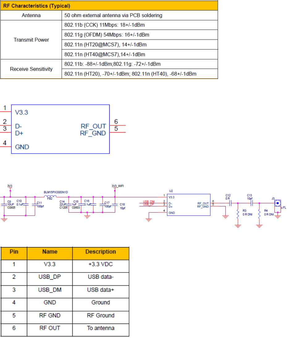
RF Performance
Module Schematic Symbol
Reference Use Schematic
Pin Description

3
Footprint
Bottom View
Antenna Installation
The module shall be mounted on a host PCB. A 50 ohm trace shall interface between pin 6 of the
module and the antenna. In order to optimize the RF performance, a matching network may be needed
along the 50 ohm trace. It is highly recommended that the distance between the RF port, pin 6 of the
module, and the antenna port is less than 30mm to minimize the signal loss. The module can be
interfaced with various types of single-ended antennas operating in 2.4GHz ISM band.
The following antenna is recommended for operating with this module.
The antenna(s) used for this transmitter must be installed to provide a separation distance of at least 20
cm from all persons and must not be co-located or operating in conjunction with any other antenna or
transmitter except in accordance with FCC multi-transmitter product procedures.
Antenna Manufactuer: AIR802
Model Number: ANRD245X02-RPSMA
Electrical Specifications
• Frequency 2400 - 2485 MHz
• Gain 2 dBi at 2.4 GHz
• VSWR < 1.5 at 2.4 GHz
• Polarization Vertical
• Vertical Beam Width 47°
• Horizontal Beam Width 360°
• Impedance 50Ω
• Max. Input Power 5 watts
• Weight 0.022 lbs (10 grams)
• Length 4.27 inches (108.5 mm)
• Connector Reverse Polarity SMA (RP-SMA) Plug (Male)
• Finish Matte Black

4
50 ohm Trace & PCB Layout Example
The following diagram shows the recommended PCB stack up configuration for the RF signal trace to
have 50 ohms characteristic impedance. A microstrip structure is highly recommended on the host PCB
to maintain RF signal integrity.
In additional to the RF trace impedance on the PCB, matching network may be needed to properly
interface with the antenna. The following diagram shows the matching network placement in one
particular application.
C12 = 0 Ω
R6 = 0 Ω
C11 = 10 pF
R5 = 0 Ω
EUT RF I/O PORT
ANTENNA INTERFACE PORT
Dielectric thickness, H1 = 12 mils
Relative dielectric constant, Er1 = 4.2
Trace width, W1/2 = 22 mils
Ground strip separation, D1 >22mils
Copper thickness, T1 = 2.1 mils
5
Host PCB 50 ohm Impedance Validation
The impedance of the microstrip RF trace must be measured on the host PCB between pad 26 of the Wi-
Fi module and the center mounting oad of the u.FL connector (pad 1 of J6) shown in the previous
diagram with the RF coupling capacitor, C11, installed. A vector network analyzer (Agilent N5230A) or a
Polar Impedance Control Test System or equivalent test equipment shall be used to conduct this test.
The impedance measured must be within +/- 10% of 50 ohm in order for the PCB to be acceptable for
usage.
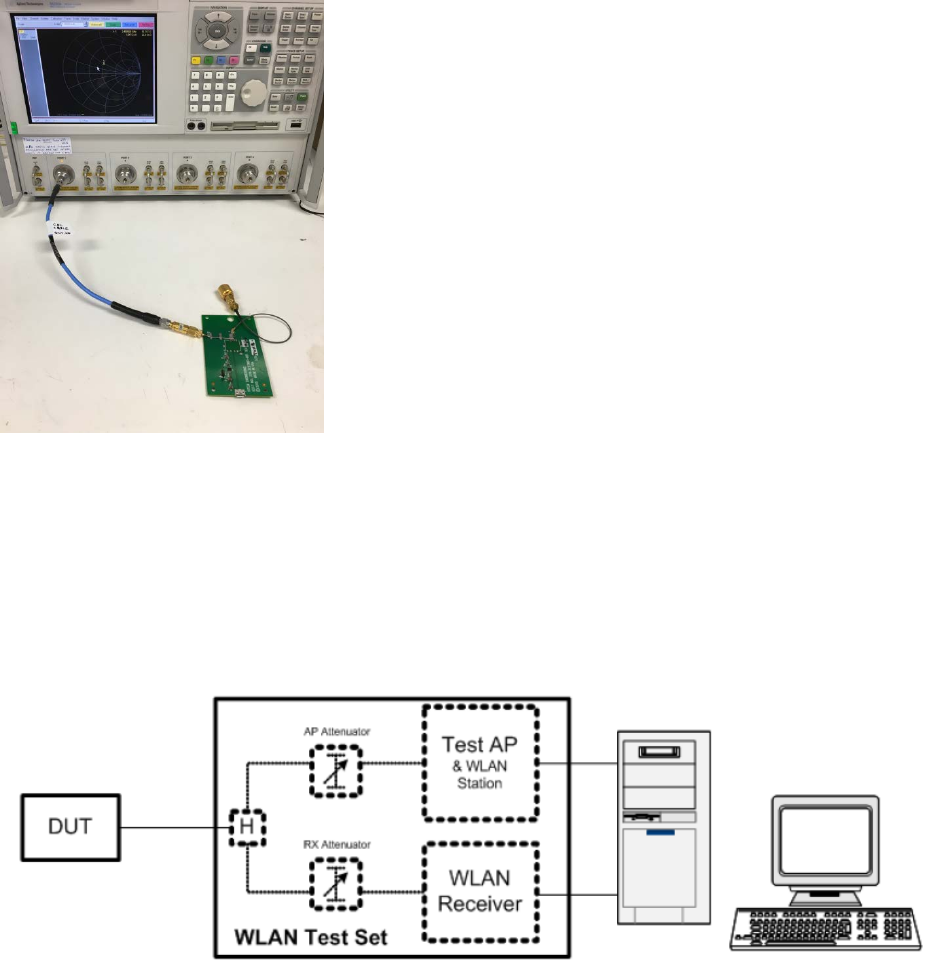
The following picture is an example of the 50 ohm impedance test setup.
Module Test Method
The purpose of the test is to ensure the operation of the module once it has been installed on a host PCB. The
following diagram shows the test setup. The WLAN test set is a LitePoint WLAN test set or equivalent equipment.
Since the module has been installed on the host PCB, the connection between the test set and the module will be
the antenna port on the host PCB. Using the test software the WLAN test set will conduct various tests to ensure
the RF signal quality in both transmit and receive modes. This will also ensure the compliance of the FCC
regulations.

6
FCC Certification
This device complies with Part 15 of the FCC Rules. Operation is subject to the following two
conditions: (1) this device may not cause harmful interference, and (2) this device must accept any
interference received, including interference that may cause undesired operation.
Labeling Instruction
If using a permanently affixed label, the modular transmitter must be labeled with its own FCC
identification number, and, if the FCC identification number is not visible when the module is
installed inside another device, then the outside of the device into which the module is installed
must also display a label referring to the enclosed module. This exterior label can use wording
such as the following: “Contains Transmitter Module FCC ID: 2ADXI-SBHD10” or “Contains FCC
ID: 2ADXI-SBHD10” Any similar wording that expresses the same meaning may be used.