Skyline Partners Technology Fastback Networks 102 Intelligent Backhaul Radio UNII 5.3GHz band User Manual OEM Volume Ag Bass
CBF Networks, Inc., dba Fastback Networks Intelligent Backhaul Radio UNII 5.3GHz band OEM Volume Ag Bass
Contents
- 1. Installation Guide
- 2. User Manual
Installation Guide

IBR Installation Guide
Page 2 of 32 Doc # 770-00001-3
Aug. 30, 2013
PURPOSE
This Installation Guide provides detailed information related to initial configuration and
installation of Fastback Network’s Intelligent Backhaul Radio (“IBR”). Supporting
information is contained in the IBR Administration & Command Line Interface Guide (“CLI
Guide”).
Table of Contents
Federal Communications Commission (FCC) Compliance Statement 4
1. Introducing Intelligent Backhaul Radio (“IBR”) 5
1.1 Overview .......................................................................................................................................................... 5
1.2 Transmit & Receive Frequencies ...................................................................................................................... 5
1.3 Radio Features................................................................................................................................................. 5
1.4 Switch Features ............................................................................................................................................... 5
1.5 Regulatory Compliance ................................................................................................................................... 6
1.6 Deployment Options ........................................................................................................................................ 6
1.7 Physical & Environmental Features ................................................................................................................. 7
2. Getting Started 7
2.1 Physical Inspection .......................................................................................................................................... 7
2.2 Inventory ......................................................................................................................................................... 8
2.3 External Features ............................................................................................................................................ 8
2.4 Power Requirements ...................................................................................................................................... 9
2.5 Technical Assistance ........................................................................................................................................ 9
3. Communicating with IBR 9
3.1 Access Control ................................................................................................................................................. 9
3.2 Serial Console .................................................................................................................................................. 9
3.3 Remote Access & Default IP Addresses ........................................................................................................ 10
3.4 Command Line Interface (“CLI”) .................................................................................................................... 10
3.5 Antennas ....................................................................................................................................................... 11
3.6 Gigabit Ethernet Ports ................................................................................................................................... 11
3.7 Interfaces ....................................................................................................................................................... 11
3.8 External Ethernet connectors ........................................................................................................................ 11
3.9 LEDs ............................................................................................................................................................... 11
4. Preconfiguring IBR 11
4.1 Orienting IBRs For Bench Test And Preconfiguration .................................................................................... 11
4.2 Applying Power ............................................................................................................................................. 12
4.3 Logging Onto IBR Using Factory-Set User Name & Password ...................................................................... 12
4.4 Entering CLI User Mode ................................................................................................................................. 12
4.5 Entering CLI Privileged Mode ........................................................................................................................ 12
4.6 Confirming VLAN Settings ............................................................................................................................. 13
4.7 Displaying IBR IP Address .............................................................................................................................. 13
4.8 Separating Management Traffic From Data Traffic ...................................................................................... 13
4.9 Saving New Configuration ............................................................................................................................. 16
4.10 Changing Host Name .................................................................................................................................... 16
4.11 Changing Passwords ..................................................................................................................................... 16
4.12 Password Recovery ........................................................................................................................................ 16
4.13 Setting System Clock ..................................................................................................................................... 16
4.14 Configuring IBR Name Server ........................................................................................................................ 17
4.15 Configuring IBR NTP Server ........................................................................................................................... 17
4.16 Configuring IBR SNMP Server ........................................................................................................................ 17
4.17 Setting Link ID ............................................................................................................................................... 17

IBR Installation Guide
Page 3 of 32 Doc # 770-00001-3
Aug. 30, 2013
4.18 Establishing A Radio Link ............................................................................................................................... 18
5. MAC Address Table & Counters 18
5.1 MAC Address Table........................................................................................................................................ 18
5.2 Counters ........................................................................................................................................................ 18
6. Installing IBR 19
6.1 Installation Checklist ..................................................................................................................................... 19
6.2 Safety Considerations .................................................................................................................................... 20
6.3 Mounting IBR ................................................................................................................................................ 20
6.4 Connecting Power & Ethernet ....................................................................................................................... 24
6.5 Connecting The Serial Port (Optional) ........................................................................................................... 24
6.6 Establishing A Link ......................................................................................................................................... 25
6.7 IAS - Link Interference Analysis ...................................................................................................................... 25
7. Features & Functionality 25
7.1 Communication Protocols ............................................................................................................................. 25
7.2 Software Management ................................................................................................................................. 25
7.3 SNMP ............................................................................................................................................................. 25
7.4 Switching & Transport ................................................................................................................................... 26
7.5 Data Handling ............................................................................................................................................... 26
7.6 Carrier Ethernet ............................................................................................................................................. 26
7.7 Timing & Synchronization ............................................................................................................................. 26
7.8 Network Time Protocol (NTP) ........................................................................................................................ 26
7.9 System Message Logging .............................................................................................................................. 27
7.10 Quality of Service (QoS) & Class of Service (CoS) ........................................................................................... 27
7.11 Security .......................................................................................................................................................... 27
7.12 Electromagnetic Interference (“EMI”) Abatement ........................................................................................ 27
Appendix A – IBR Mounting Brackets 28
A 1. Wall/Pole Mounting Bracket ......................................................................................................................... 28
A 2. Articulating Mount ........................................................................................................................................ 31

IBR Installation Guide
Page 4 of 32 Doc # 770-00001-3
Aug. 30, 2013
Federal Communications Commission (FCC) Compliance Statement
This equipment has been tested and found to comply with the limits for a Class B digital
device pursuant to Part 15 of the FCC Rules. These limits are designed to provide
reasonable protection against harmful interference when the equipment is properly
installed and operated in accordance with instructions contained in this manual. The
equipment should not be operated if it becomes out of compliance with FCC Rules. In order
to ensure continued compliance with FCC Rules, the equipment:
o Should be installed in a restricted area that is accessible only by authorized service
personnel.
o Should not be operated if it is or becomes damaged.
o Should be connected to other devices by shielded cables of the correct types.
o Should not be repaired or modified except by Fastback Networks.
Failure to comply with these instructions could void the operator’s authorization to operate
the equipment.

IBR Installation Guide
Page 5 of 32 Doc # 770-00001-3
Aug. 30, 2013
1. Introducing Intelligent Backhaul Radio (“IBR”)
1.1 Overview
IBR combines a Carrier Ethernet switch and an SC-FDE
1
radio in a small, passively-cooled,
environmentally protected package for use in 4G cellular backhaul and fiber extension
applications. It is designed for small cell deployment in dense urban environments where
line of sight between radios is difficult or impossible to achieve. IBR can be mounted on
masts, poles, walls, cell towers, or in other such locations and does not require precise
antenna alignment for reliable communications.
NOTE: For safety reasons and FCC compliance, IBR should be installed in a restricted
access location that is accessible only by authorized service personnel.
1.2 Transmit & Receive Frequencies
There are two versions of IBR that operate together to form the two ends of a link.
o IBR58, a 5.8 GHz radio, transmits in the band from 5.725 GHz to 5.85 GHz and
receives in the band from 5.25 GHz to 5.35 GHz.
o IBR53, a 5.3 GHz radio, transmits in the band from 5.25 GHz to 5.35 GHz and
receives in the band from 5.725 GHz to 5.85 GHz.
1.3 Radio Features
IBR uses adaptive rate modulation, proprietary interference avoidance and cancellation
techniques, and antenna array signal processing to deliver reliable and secure high speed
data transmission over links where line-of-sight between radios is difficult or impossible to
achieve. The table below shows IBR performance in a typical installation.
IBR Performance
2
Data Rate
Scalable to 500 Mbps
Average Latency
< 500 μsec
Operating Range
Up to 500m NLOS3 and 2Km LOS4
Operating Frequencies
5.25 to 5.35 GHz and 5.725 to 5.85 GHz (U-NII/ISM5)
EIRP
< 30 dBm (5.3 GHz); < 36 dBm (5.8 GHz)
1.4 Switch Features
IBR provides the following Carrier Ethernet 2.0 features:
o Layer 2 transport
- VLAN (up to 4096)
- Bridge mode (pass through)
o Management
- CLI
- Telnet
- SSH
- Serial console
1
Single-carrier-based frequency domain equalization
2
Performance might vary depending on environmental conditions
3
Non-line-of-sight
4
Line-of-sight
5
Unlicensed National Information Infrastructure/ Industrial, Scientific, & Medical
IBR Installation Guide
Page 6 of 32 Doc # 770-00001-3
Aug. 30, 2013
- SNMP MIB support
- Interface-MIB
- MIB II
- Enterprise MIB
o Packet-based timing – 1588v2 transparent clock w/submicrosecond latency
o QinQ (IEEE 802.1ad)
o QoS
- Eight queues
- 802.1p classification
- Strict scheduling
- PIR shaping
o 256 bit AES encryption
o Physical link and network layer redundancy for maximum service uptime
o Service protection and reliability
1.5 Regulatory Compliance
IBR is compliant to the applicable portions of the following standards.
o Radiation: FCC Part 15
o EMC/EMI
6
: FCC Part 15 Class B
o NEBS
7
: GR-3108
o Safety: UL 60950-1, UL 60950-22, CAN 60950-1
o Environmental: IP66
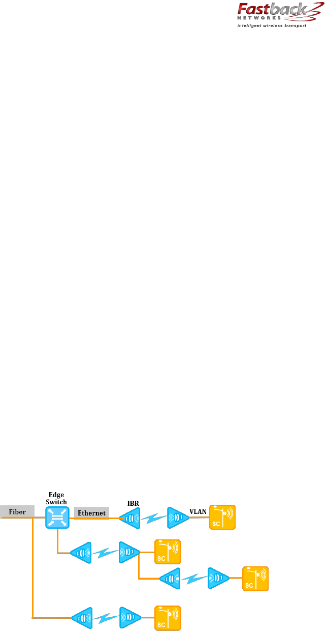
1.6 Deployment Options
IBR is designed to be deployed in pairs creating a point-to-point link, as illustrated in the
diagram below. In referring to the two radios, IBR nearest to the fiber connection is called
the “aggregation IBR” and the one nearest to the cell site is the “remote IBR”.
o IBR can be connected to an edge switch.
o IBRs can be connected to one another in a multi-hop configuration.
o IBR can provide backhaul for a direct connection to a small cell site (SC).
6
Electromagnetic Compatibility/Electromagnetic Interference
7
Network Equipment Building Systems
IBR Installation Guide
Page 7 of 32 Doc # 770-00001-3
Aug. 30, 2013
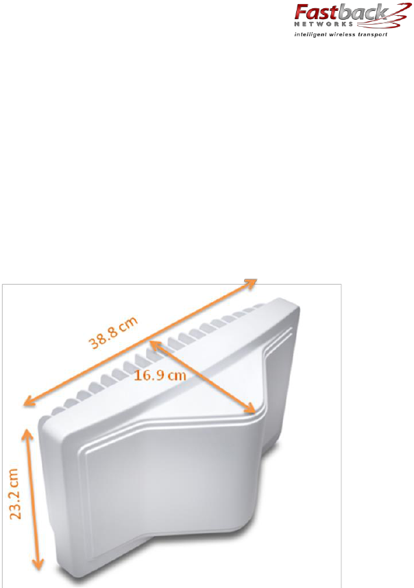
1.7 Physical & Environmental Features
IBR:
o Is passively cooled and can operate continuously at full power and duty cycle under
maximum solar load at ambient temperatures from -40o C to +60o C.
o Can be stored safely at temperatures in the range from -55o C to +85o C.
o Experiences a wind load of less than 300N when exposed to a wind speed of 265
km/hr.
o Has an IP66
8
environmental rating.
IBR weighs approximately 4 kg and has the approximate dimensions shown in the
illustration.
2. Getting Started
2.1 Physical Inspection
Prior to opening the shipping crate, inspect it visually for evidence that it has been opened or
mishandled. After opening the crate, carefully inspect the contents for completeness or
evidence of damage or tampering.
In the event the shipping crate is damaged or the contents are damaged or incomplete, notify
Fastback Networks by telephone, fax, or email. The shipping crate, dividers, and packing
materials should be retained for use in the event that equipment must be returned to
Fastback Networks.
After removing IBR from its packing crate, record the serial number and model number
(IBR58 or IBR53), both of which will be needed in case it is necessary to seek assistance from
Fastback Network’s Customer Support Group.
DO NOT BREAK THE TAMPER SEALS ON HARDWARE. DOING SO WILL VOID THE
WARRANTY AND MIGHT CREATE A SAFETY HAZARD AND/OR CAUSE THE EQUIPMENT TO
BE OUT OF COMPLIANCE WITH FCC REGULATIONS.
8
Ingress Protection Rating
IBR Installation Guide
Page 8 of 32 Doc # 770-00001-3
Aug. 30, 2013
DO NOT ATTEMPT TO APPLY POWER TO AN IBR THAT SHOWS SIGNS OF DAMAGE,
TAMPERING, OR MISHANDLING.
2.2 Inventory
The following components are required for successful installation of IBR:
(a) One IBR53, Model IBR-1000-38N and one IBR58, model IBR-1000-83N. Each IBR
includes the following:
o Three weatherproof RJ-45 cable-end connectors for CAT5E & CAT6 cables*;
o A weatherproof cap for the four-pin serial connector that is attached to IBR when
the IBR serial connector is not in use*.
o Two weatherproof caps for RJ-45 connectors that are attached to IBR when the IBR
RJ-45 connectors are not in use*.
o A two-meter serial cable with a DB-9 connector on one end and a four-pin connector
on the other end;
o Six crimp-on ends for RJ-45 connectors & instructions
o An information sheet for accessing regulatory documents and manuals on line;
o A quick reference guide;
o A warranty registration card;
*Note: For proper operation of IBR, the weatherproof integrity of all cables and connectors
should be maintained and weatherproof caps should be firmly installed on unused
connectors at all times.
(b) A mounting bracket for each IBR. Fastback Networks can supply two types: (a) a fixed
wall/pole mount, model IBR-AC-BRP, and (b) an articulating wall/pole mount, model
IBR-AC-BRA.
(c) A PoE+ injector for each IBR; model IBR-AC-PON.
(d) A PoE Injector Mounting Kit, model IBR-AC-POM for each IBR.
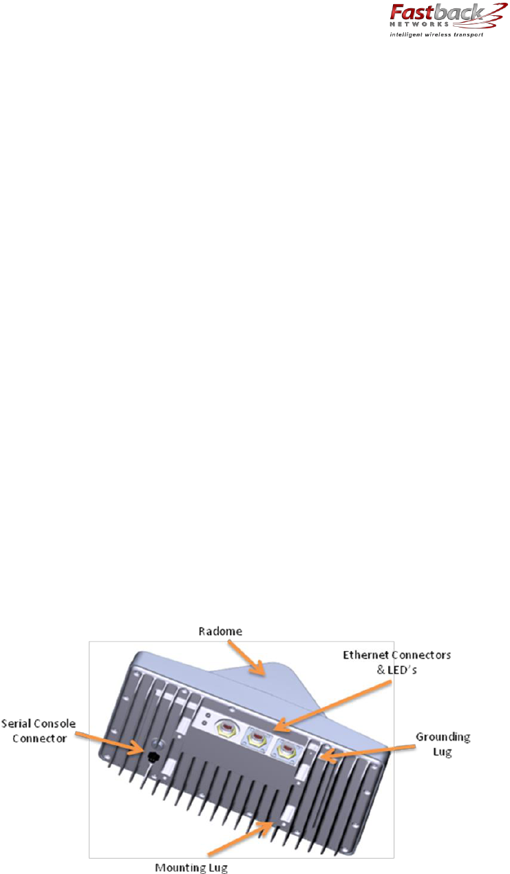
2.3 External Features
The illustration below identifies external features of IBR.
The side where the mounting lugs and serial port are located is referred to as the “back”,
since it is the side that will be against a wall or mast when IBR is mounted.

IBR Installation Guide
Page 9 of 32 Doc # 770-00001-3
Aug. 30, 2013
The side that has the three Ethernet connectors and two LEDs is referred to as the “bottom”.
Even though the connectors are weatherproof, IBR should be mounted with the connectors
facing downward for maximum environmental protection.
2.4 Power Requirements
IBR must be powered via PoE+ through the RJ-45 connector labeled Port 0. Applying PoE+
through any of the other Ethernet connectors will cause no harm, but will not power IBR.
Operating at full RF power, IBR requires less than 25.5 watts, thereby conforming to the IEEE
802.3at Type 2 standard for PoE+.
IBR does not have a capability to provide PoE to other devices on the network.
IBR may be powered by a FastBack power injector or by the PowerDsine 9001GO Power over
Ethernet (PoE) single-port Midspan injector.
2.5 Technical Assistance
In the event there is a problem with IBR or other equipment provided by Fastback Networks
( e.g., it arrives damaged or incomplete, or appears to not work properly), the operator
should contact Fastback Networks’ service center via telephone or email and be prepared to
provide:
o Product type and serial number
o Product service history (e.g., when was it received, how long has it been in service,
other relevant information)
o Description of the problem
o Customer contact information
Fastback Networks’ Customer Service can be reached by email at
customer.service@fastbacknetworks.com, or by telephone at (408) 430-5440 & select the
Service option.
3. Communicating with IBR
IBR has no external or internal keypads, switches, dials, knobs, or other physical controls.
Therefore, an operator will require a smart terminal, computer, workstation, or other such
device to communicate with IBR using command line interface and accessing IBR via any of
the Ethernet ports using Telnet or SSh or via the serial console port.
3.1 Access Control
IBR can be configured to require a valid user ID and password for access. Two levels of
access can be established: minimum functionality and full functionality. Detailed instructions
for controlling access to IBR are contained in the CLI Guide.
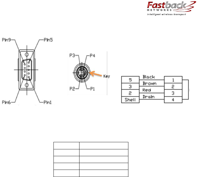
3.2 Serial Console
IBR has a four-pin connector that provides a serial interface for connection to a local
operator terminal. This interface typically will be used by an operator to communicate with
and control the IBR during preconfiguration and troubleshooting or at other times when a
local operator needs to communicate with IBR other than over an Ethernet link.
The mating cable that is provided with IBR has a DB9 connector on the other end. The
illustrations below show the pinouts of the two connectors and the cable wiring scheme.
IBR Installation Guide
Page 10 of 32 Doc # 770-00001-3
Aug. 30, 2013
This interface can be used by an operator only to control, configure, and troubleshoot IBC,
but not for general network connectivity or data transmission. Pin-outs of the four-pin serial
connector are shown in the table below.
PIN #
Purpose
1
Ground
2
Transmit
3
Receive
4
Not used
The following settings are recommended when communicating with IBR via the serial
interface:
o 115,200 bps
o 8 data bits
o 1 stop bit
o No parity
o No flow control
o 25 lines and 80 columns window size
NOTE: If a serial device is disconnected and then reconnected, CLI might be left in a “bad command” state
and not respond to legitimate commands. This condition can be cleared by entering <cr> <cr> <Ctrl-C>.
3.3 Remote Access & Default IP Addresses
IBR may be accessed remotely over the network from telnet or SSH. The default IP addresses
are:
192.168.128.53 for the 5.3 GHz IBR; and
192.168.128.58 for the 5.8GHz IBR.
The default hostnames are IBR53 and IBR58 for the 5.3 GHz and 5.8GHz IBRs, respectively.
3.4 Command Line Interface (“CLI”)
When an operator logs onto IBR, CLI will be launched in startup (i.e., “User”) mode that
provides minimal functionality.
o CLI is supported on the serial interface and via Telnet or SSH connections through
the Ethernet interface.
o CLI uses a mix of IOS syntax.
o Access to the full functionality mode (i.e., “Privileged” mode) can be controlled by
password.

IBR Installation Guide
Page 11 of 32 Doc # 770-00001-3
Aug. 30, 2013
Detailed information can be found in the CLI Guide.
3.5 Antennas
The radome on top of IBR houses transmit and receive antennas that face outward through
the flat sides of the radome. The direction in which the antennas are pointed can be changed
only by changing the orientation of the IBR itself. The CLI-based pointing tool can be used as
an aide to orient IBR for best link performance.
IBR is not designed to be used with external antennas.
3.6 Gigabit Ethernet Ports
IBR is a 4-port Ethernet switch. Three Gigabit Ethernet ports are exposed externally, and one
is connected internally to the radio. Beginning with the port nearest the LEDs, the external
Gigabit Ethernet ports are numbered 0, 1, and 2 (ge0, ge1, ge2).
The Gigabit Ethernet port that is connected to the radio (not externally available) is identified
as Gigabit Ethernet 3 (ge3). Radio parameters are configured through the radio 0 interface,
while switching parameters that apply both to the physical Gigabit Ethernet ports and the
radio port, such as VLAN, QoS, and CoS, are configured through the Gigabit Ethernet interface.
3.7 Interfaces
Ethernet interfaces, including loopback interfaces, can be created, as discussed in the CLI
Guide, and each port can be assigned to one or more interfaces.
3.8 External Ethernet connectors
o All three of the Ethernet connectors on the bottom of IBR can be used for traffic and
IBR management data, but only the one nearest the LEDs (ge0) can accept PoE+.
o There are two variants of IBR: one has three RJ-45 connectors and the other has one
RJ-45 (for ge0) and SFP
9
connectors for ge1 and ge2.
o The RJ-45 connectors will accept shielded and bonded RJ-45 type mating connectors
with a weatherproof seal. It is essential that only weatherproof connectors be
connected to IBR.
3.9 LEDs
Two weatherproof LEDs that are mounted adjacent to ge0 provide a visual means for an
operator to determine the status of IBR. Both LEDs can be deactivated via CLI command.
See the CLI Guide for detailed information. When the LEDs are active (the default condition):
o The upper LED (when the LEDs are on the left from the viewer’s perspective) will be
green when an active Ethernet link is established between IBR and another device.
This LED will be dark if no Ethernet link has been established.
o The lower LED will turn green when power is applied to IBR.
4. Preconfiguring IBR
The following procedure is for preconfiguring a pair of IBRs prior to installation.
4.1 Orienting IBRs For Bench Test And Preconfiguration
CAUTION: When power is applied, the radios automatically will begin transmitting.
9
Small form-factor pluggable fiber optic transceiver

IBR Installation Guide
Page 12 of 32 Doc # 770-00001-3
Aug. 30, 2013
To avoid the possibility of damaging an IBR by overdriving the front end of the receiver, prior
to connecting a power source, position the radios so that they are tilted away from each
other, facing downward, and separated by at least one meter.
Check the RSSI using the following CLI command in the Global Config mode:
IBR58 (config) # interface radio 0 status
RSSI should be -20dB or less. If RSSI is greater than -20 dB (e.g., -17dB, -15dB, etc.) then
further separate the radios to avoid receiver saturation.
4.2 Applying Power
CAUTION - IBR does not have a power on/off switch, either in hardware or software. When
power is applied to the unit, IBR will be in a “power on” condition and the lower LED beside
the Port 0 connector will be green unless the LED has been disabled by the operator.
Apply power to each IBR using a PoE+ source connected to Gigabit Ethernet interface 0.
4.3 Logging Onto IBR Using Factory-Set User Name & Password
When CLI is launched and the “user name” dialog box appears, the user can enter either fbn
or admin for access (unless the user name has been changed by an operator). The factory-
set password is fastback. When a user with Privileged access changes the user name,
changing either admin or fbn will cause both to be changed to the new user name.
4.4 Entering CLI User Mode
When a user logs onto IBR with a valid user name and password , CLI automatically will be in
the User Mode, which offers a limited set of commands. The CLI command prompt in User
Mode is the symbol > followed by a space. When the command prompt is displayed, it will
be preceded by the host name if one has been assigned. Throughout this manual and the CLI
Guide, the host name IBR58 will be used. The User Mode prompt is shown below:
IBR58 >
The host name can be changed or omitted by a Privileged user. The commands shown below
are the only commands available in User mode.
User Commands
Mode/Command Remarks
IBR> User Mode
enable Enter Privileged Mode
ping Determine (a) if a remote host is active & (b) transit time
traceroute Determine route & transit time to a remote host
exit Close CLI
4.5 Entering CLI Privileged Mode
Enter Privileged (“Priv”) mode by entering the enable command:
IBR58 > enable
The default password for entering Priv mode is fastback.
All CLI commands are available in Priv mode. For a detailed discussion of CLI commands,
refer to the CLI Guide.

IBR Installation Guide
Page 13 of 32 Doc # 770-00001-3
Aug. 30, 2013
4.6 Confirming VLAN Settings
By default, VLAN functionality is enabled on IBR and all interfaces are assigned to VLAN1.
During initial configuration, the operator should assign VLANs to interfaces as desired. IBR
can be managed using any VLAN to which an IP address is assigned. See the section titled
Separating Management Traffic From Data Traffic for details on assigning an IP address to a
VLAN and using VLANs to segment management traffic from data traffic.
Interfaces may be configured to support both tagged and untagged packets. Each IBR
interface can be configured to support ingress and egress of tagged packets for all VLANs
connected to the interface except for a VLAN that is configured as native to that interface.
Packets tagged with the VLAN number that is configured as the native VLAN for an interface
will be dropped.
Enter the following command to confirm that vlan1 is enabled.
IBR58 # show vlan brief
Returns: VLAN1 Active ge0 ge1 ge2 ge3
The response (“Returns”) shown above indicate that vlan1 is attached to all four interfaces.
4.7 Displaying IBR IP Address
Enter the following command to confirm that IBR has been assigned an IP address.
IBR58 # show ip interfaces
This command will return an output similar to the following example:
1: lo: <LOOPBACK> mtu 16436 qdisc noop
link/loopback 00:00:00:00:00:00 brd 00:00:00:00:00:00
2: eth0: <BROADCAST,MULTICAST,UP,LOWER_UP> mtu 1500 qdisc pfifo_fast qlen 1000
link/ether 18:48:d8:00:00:39 brd ff:ff:ff:ff:ff:ff
3: danipc: <BROADCAST,MULTICAST,UP,LOWER_UP> mtu 1500 qdisc pfifo_fast qlen 1000
link/ether 00:24:86:00:00:00 brd ff:ff:ff:ff:ff:ff
4: eth0.1@eth0: <BROADCAST,MULTICAST,UP,LOWER_UP> mtu 1500 qdisc noqueue
link/ether 18:48:d8:00:00:39 brd ff:ff:ff:ff:ff:ff
inet 10.21.2.195/16 brd 10.21.255.255 scope global
Following the first three interfaces in the output, there will be an additional interface for each
VLAN. The name of the interface is eth0.nn where nn is the VLAN number to which the IP
address is assigned. Note that even though the interface shows eth0, the IP address will be
reachable only through interfaces to which that VLAN has been assigned.
4.8 Separating Management Traffic From Data Traffic
IBR interfaces should be configured in such a way as to separate internal management traffic
from user data traffic (i.e., prevent management traffic from being sent over the network).
The following sequence of commands illustrates a way to accomplish this. VLAN2, VLAN823,
and the IP addresses shown are used only as examples.
4.8.1 Create VLAN interfaces

IBR Installation Guide
Page 14 of 32 Doc # 770-00001-3
Aug. 30, 2013
Prompt
Command
Remarks
IBR58 (config)#
interface vlan 1
Configure vlan1
IBR58 (config-vlan-1)#
ip address 192.168.128.158 255.255.255.0
IBR58 (config-vlan-1)#
exit
IBR58 (config)#
interface vlan 2
IBR58 (config-vlan-2)#
no shutdown
IBR58 (config-vlan-2)#
ip address 10.22.12.201 255.255.0.0
IBR58 (config-vlan-2)#
exit
IBR58 (config) #
interface vlan 823
IBR58 (config-vlan-823) #
ip address 10.1.1.158 255.255.0.0
IBR58 (config-vlan-823) #
exit
IBR58 (config) #
Note: When the management port has been reassigned, the Telnet connection will be lost and
the operator will be required to Telnet to the new management port address.
4.8.2 Remove VLAN 1 from ge1, g2, and ge3.
Prompt
Command
Remarks
IBR58 (config)#
interface gigabitethernet 1
IBR58 (config-if-ge1)#
no switchport trunk native vlan 1
IBR58 (config-if-ge1)#
exit
IBR58 (config)#
interface gigabitethernet 2
I IBR58 (config-if-ge2)#
no switchport trunk native vlan 1
IBR58 (config-if-ge2)#
exit
IBR58 (config) #
interface gigabitethernet 3
IBR58 (config-if-ge3)#
no switchport trunk native vlan 1
IBR58 (config-if-ge3)#
exit
IBR58 (config) #
interface vlan 823
4.8.3 Add VLAN 2 to the GigabitEthernet Interfaces (use Trunk Native)
Prompt
Command
Remarks
IBR58 (config)#
interface gigabitethernet 1
IBR58 (config-if-ge1)#
switchport trunk native vlan 2
IBR58 (config-if-ge1)#
exit
IBR58 (config)#
interface gigabitethernet 2
I IBR58 (config-if-ge2)#
switchport trunk native vlan 2
IBR58 (config-if-ge2)#
exit
IBR58 (config) #
interface gigabitethernet 3
IBR58 (config-if-ge3)#
switchport trunk native vlan 2
IBR58 (config-if-ge3)#
exit
IBR58 (config) #
interface vlan 823
4.8.4 Add VLAN 823 to GigabitEthernet 3 (use Trunk Allowed)
Prompt
Command
Remarks
IBR58 (config) #
interface gigabitethernet 3
IBR58 (config-if-ge3)#
switchport trunk allowed vlan 823
IBR58 (config-if-ge3)#
exit
4.8.5 Verify VLAN settings
IBR Installation Guide
Page 15 of 32 Doc # 770-00001-3
Aug. 30, 2013
Prompt
Command
Remarks
IBR58 #
show vlan brief
VLAN Name Status Native Allowed
---- ---------------- --------- ---------------- ---------------------------------------------
1 VLAN1 active ge0 ge0
2 VLAN2 active ge1 ge2 ge3 ge1 ge2 ge3
823 VLAN823 active ge3 ge3
IBR58 #
4.8.6 Confirm that the interfaces were correctly configured.
Prompt
Command
Remarks
IBR58 #
show ip interfaces
1: lo: <LOOPBACK,UP,LOWER_UP> mtu 16436 qdisc noqueue
link/loopback 00:00:00:00:00:00 brd 00:00:00:00:00:00
inet 127.0.0.1/8 scope host lo
2: eth0: <BROADCAST,MULTICAST,UP,LOWER_UP> mtu 1500 qdisc pfifo_fast qlen 1000
link/ether 18:48:d8:00:00:49 brd ff:ff:ff:ff:ff:ff
3: danipc: <BROADCAST,MULTICAST,UP,LOWER_UP> mtu 1500 qdisc pfifo_fast qlen 1000
link/ether 00:24:86:00:00:00 brd ff:ff:ff:ff:ff:ff
4: eth0.1@eth0: <BROADCAST,MULTICAST,UP,LOWER_UP> mtu 1500 qdisc noqueue
link/ether 18:48:d8:00:00:49 brd ff:ff:ff:ff:ff:ff
inet 192.168.128.158/24 brd 192.168.128.255 scope global eth0.1
5: eth0.2@eth0: <BROADCAST,MULTICAST,UP,LOWER_UP> mtu 1500 qdisc noqueue
link/ether 18:48:d8:00:00:49 brd ff:ff:ff:ff:ff:ff
inet 10.22.12.201/16 brd 10.22.255.255 scope global eth0.2
6: eth0.823@eth0: <BROADCAST,MULTICAST,UP,LOWER_UP> mtu 1500 qdisc noqueue
link/ether 18:48:d8:00:00:49 brd ff:ff:ff:ff:ff:ff
inet 10.1.1.158/16 brd 10.1.255.255 scope global eth0.823
IBR58 #
4.8.7 Reviewing the new configuration.
The configuration created in this section creates three distinct interfaces for use on the IBR.
(a) eth0.1 is the management interface on VLAN1 (the default VLAN on IBR). VLAN1 has
been assigned to GigabitEthernet port ge0 and given the IP address 10.21.12.211/16.
This interface is isolated from the other interfaces and can be used to access the IBR and
manage the switch without allowing management traffic to traverse the RF link or go out
onto the network.
(b) eth0.2 is the data interface on VLAN 2, which has been assigned to GigabitEthernet ports
ge1, ge2, and ge3.
Traffic on VLAN2 can be sent across the RF link and out onto the network. It allows all
untagged traffic and traffic tagged with VLAN ID 2 to be sent to the network.
GigabitEthernet ports 1 and 2 are physical ports allowing connections to the provider
network.
GigabitEthernet 3 is dedicated to the IBR RF link and creates a wireless bridge between
two network segments.
(c) eth0.823 is an isolated debug interface on VLAN 823.
VLAN823 will allow traffic only to be sent from one IBR to the other across the wireless
link and requires that the sender be logged onto one of the IBRs.

IBR Installation Guide
Page 16 of 32 Doc # 770-00001-3
Aug. 30, 2013
One use of this interface is to allow a user to send ping packets to the opposite IBR to
verify link integrity. This VLAN has no exposure to a physical network interface so traffic
on this VLAN is isolated from the network.
4.9 Saving New Configuration
Use the following commands to save the new settings to the startup configuration file.
IBR58 (config)# copy running-config start-up config
4.10 Changing Host Name
Change the host name using the following command in Global Config mode.
IBR58 (config) # host name [newname]
4.11 Changing Passwords
The command for setting or changing a password has the following form:
IBR58 # enable password {level (1, 15)} [newpassword]
where “level” must either be the number 1 or the number 15 and newpassword must be a
string of at least six and not more than sixteen characters and can include any letter, any
numeral, and any of the following symbols: ! @ # $ % .
o When level = 1, the password to enter User Mode will be affected.
o When level = 15, the password to enter Privileged Mode will be affected.
When no level option is entered, Privileged Mode will be affected.
4.12 Password Recovery
In the event that the Privileged Mode password is forgotten, the following procedure can be
used to reset all IBR settings to their default values, thereby allowing a user to regain
access to IBR. This procedure will boot IBR into a Linux root shell single-user mode where
the user can change the Privileged Mode password.
o Initiate a system reboot and, within two (2) seconds, press any key to interrupt the
reboot process. Enter the following command when the uMON> prompt is
displayed:
uMON> run flash linuxsingle
o IBR will take several minutes to reboot. When the Linux prompt is displayed, enter
the command passwd root and then respond to the succeeding prompts to change
the Privileged Mode password and reboot the system.
o When IBR reboots to CLI User Mode, use the default user name and password to log
onto the system. Use the new Privilege Mode password to enter Privilege Mode.
o Then follow the standard procedure to change the User Mode Unser name and
password.
4.13 Setting System Clock
The command to set the IBR system clock is executed in Global Config mode and has the
following form.
IBR58 (config) # clock set [hh:mm:ss] [YYYY-MM-DD]
where all of the arguments are integers.

IBR Installation Guide
Page 17 of 32 Doc # 770-00001-3
Aug. 30, 2013
4.14 Configuring IBR Name Server
The following command can be used to configure the Name server.
IBR58 (config)# ip name-server [ip-address}
4.15 Configuring IBR NTP Server
The following command can be used to configure the NTP server.
IBR58 (config)# ntp server [ip-address}
4.16 Configuring IBR SNMP Server
The following sequence of commands can be used to configure the SNMP server.
IBR58 (config) # snmp-server host [ip-address]
IBR58 (config) # snmp-server community [com-name]
IBR58 (config) # snmp-server group [grp-name]
IBR58 (config) # snmp-server view [vname]
Examples of configuring an SNMP Server are shown below.
Setting up an SNMPv2 Trap Server
Prompt
Command
Remarks
IBR58 (config) #
snmp-server community fastback rw
Use “fastback” or read/write
IBR58 (config) #
snmp-server host 10.0.0.1 traps version v2c
Traps SNMPv2
IBR58 (config) #
exit
Return to Global Config
IBR58 #
show snmp-server host
Returns
Notification Host: 10.21.0.4
udp-port: 162
type: inform
user: snmptraps
security model: v2c
Notice the community string
is not returned with the show
command
Setting up a Default Gateway
Prompt
Command
Remarks
IBR58 (config) #
ip default-gateway 10.10.0.1
Config radio interface “0”
IBR58 (config) #
exit
Return to Global Config
IBR58 #
show ip route
Returns
10.10.0.0/16 dev eth0.53 src 10.1.1.10
default via 10.10.0.1 dev eth0.1
Default gateway using VLAN 1
4.17 Setting Link ID
The command to set Link ID has the following syntax:
IBR58 (config) # link-id [linkname]
where linkname is an alphanumeric string from one to thirty-two characters in length that
can contain any of the following symbols: ! @ # $ % - _
Using Link ID Command
Prompt
Command
Remarks
IBR58 (config) #
interface radio 0
Config radio interface “0”
IBR58 (config-if-rad0) #
link-id 58$a2
Sets link ID to “58$a2”
IBR58 (config-if-rad0) #
exit
Return to Global Config

IBR Installation Guide
Page 18 of 32 Doc # 770-00001-3
Aug. 30, 2013
IBR58 (config) #
4.18 Establishing A Radio Link
IBRs will automatically establish a link using the best frequencies to optimize data
throughput. IBR has a software feature called “Pointing Tool” that will aid in quickly and
properly aligning IBRs for best link performance. It will not be necessary to use this feature
in a laboratory setting where the two ends of a link are within sight of one another.
Use of the pointing tool is discussed in detail in the section titled Installing IBR.
5. MAC Address Table & Counters
IBR contains one table and twenty counters.
5.1 MAC Address Table
The MAC Address table, sometimes referred to as the L2 (or Layer 2) table, associates MAC
addresses with their respective VLAN’s and ports. L2 is the only table in IBR and cannot be
deactivated.
When a packet is received by IBR, IBR automatically records the MAC address of the received
packet and the port on which it was received. When an incoming packet arrives at IBR, the
correct port and VLAN for delivery of the packet is determined by comparing the MAC
address of the packet with the corresponding entry in L2. If the MAC address is not in L2, IBR
will send the packet out to all ports except the one on which it was received, and then record
the port and VLAN of the device that responds to the packet.
When a MAC address in the L2 table has not been used within a preset time (the “aging
time”), that entry is automatically deleted from the table. The default aging time is three
hundred (300) seconds; however, aging time is a user-configurable property. Aging time is
the only property of L2 that can be changed. L2 can contain up to sixty-four thousand entries
so that, with a reasonable aging time, there is little chance of an overflow condition.
Using the CLI “show” command, an operator can display the contents of L2.
5.2 Counters
Counters are implemented as two-dimensional arrays that associate traffic data with the
corresponding IBR ports (interfaces). Counters are activated by default and cannot be
disabled; however, the contents of counters can be reset to zero or displayed by operator
command. Counters are identified by the names shown below.
(a) InBytes Bytes received at a port
(b) InUcastPkts ------------ Unicast packets received at a port
(c) InMcastPkts Multicast packets received at a port
(d) InBcastPkts ------------ Broadcast packets received at a port
(e) OutBytes Bytes sent from a port
(f) OutUcastPkts ---------- Unicast packets sent from a port
(g) OutMcastPkts Multicast packets sent from a port
(h) OutBcastPkts ---------- Broadcast packets sent from a port
(i) CrcAlign-Err Frames rcvd that don’t have an even # of octets or have CRC errors
(j) Dropped-Bad-Pkts --- Rcvd packets dropped for errors
(k) Collisions Collisions before successful transmission
(l) Symbol-Err ------------ Symbol errors
(m) Undersize Frames rcvd that are < 64 bytes
(n) Oversize ---------------- Frames rcvd that are > 1514 bytes
(o) Fragments Oversized packets sent as fragments

IBR Installation Guide
Page 19 of 32 Doc # 770-00001-3
Aug. 30, 2013
(p) Jabbers ------------------ Frames longer than 1518 octets
(q) Single-Col # of times only one collision occurred before successful xmsn
(r) Multi-Col --------------- # of times multiple collisions occurred before successful xmsn
(s) Late-Col Collisions detected after > 512 bits sent
(t) Excess-Col -------------- Frames not sent due to excess # of retries
(u) Drops TX queue drops
(v) Octets ------------------ TX queue octets
(w) Packets TX queue packets
6. Installing IBR
6.1 Installation Checklist
o A pretested and preconfigured IBR.
o A mounting bracket that is suitable for the intended location and mounting
hardware.
o Access to a PoE+ source.
o Hand tools and materials as appropriate from the list below:
All Mounts:
Pole mount: Banding strap or hose clamp, maximum ¾” strap width of
appropriate length for the pole diameter.
Wall mount: 8mm or 5/16” diameter bolt appropriate for the mounting
surface.
Articulating mount:
Torque wrench to tighten all connections to 10 ft-lbs.
2 x 13mm open-ended wrench or sockets for the M8 mounting bolts.
5mm Allen wrench for the socket button-head cap screws to attach the
mount to the IBR.
Wall / Pole mount:
4.5mm Allen wrench for the M6 socket button-head cap screw that connects
the two parts of the mount together.
5mm Allen wrench for the socket button-head cap screws to attach the
mount to the IBR.
Ethernet connections:
17mm open-ended wrench to tighten the weatherized Ethernet boot. See
the section on Ethernet connectors for torque specifications.
RJ45 Ethernet termination tools.
Ethernet cables. The IBR has an integrated switch and can accept up to 3
individual Ethernet connections, though only one is absolutely required to
pass data.
Serial connection (required for initial configuration):
USB-to-DB9 converter. Required if the PC used for configuration does not
have a DB9 connector. Most PCs don’t have a DB9 connector, so this is
almost always required.
o A safe and suitable means of lifting the equipment and installer at the installation
site. (NOTE: The mounting bracket for IBR has holes that can be used to suspend
IBR from a utility belt or otherwise as an aid in lifting IBR.)
o Shielded Ethernet cable.
o A laptop with a USB-to-DB9 serial adapter for communicating with IBR via the serial
port or Ethernet.

IBR Installation Guide
Page 20 of 32 Doc # 770-00001-3
Aug. 30, 2013
6.2 Safety Considerations
o Ensure that grounding is in accordance with local codes.
o Use lifting methods and/or equipment that are appropriate for the location; e.g., pole
climbing equipment, ladder, power lift.
o Note the locations of other equipment, power lines, vehicle traffic, and other
potential safety hazards at the installation site.
6.3 Mounting IBR
IBR must be mounted on a suitable bracket that will hold IBR securely under all
environmental conditions. The base of IBR has four mounting posts for mounting bolts set in
a square pattern. Operators have the option to use a mounting bracket purchased from
Fastback Networks or to create custom mounting solutions.
Fastback offers two mounting bracket options, an articulating bracket and a fixed, or non-
articulating, bracket, each of which can be mounted either on a wall or a pole. Guides for
installing these brackets are shown below. Appendix A contains additional descriptions and
images of the mounting brackets that are available from Fastback Networks.
6.3.1 Mounting Location - Choosing the best possible mounting location for IBR is important for
safety, security, and link performance.
o Install IBR in a location where access is restricted to authorized service personnel.
o For best performance, IBR should be mounted so that it is within + five degrees of
level (horizontal plane) and + five degrees of plumb (vertical plane).
o Select a location that is near to IBR’s required interconnect point and PoE+ source;
o Avoid areas that are subject to vibration, heat, RF emissions, or other such
disturbances from nearby equipment;
o Locate and orient IBR as near as possible to obtain line-of-sight to the distant IBR;
o Avoid locations that might present hazards to installation or maintenance crews.
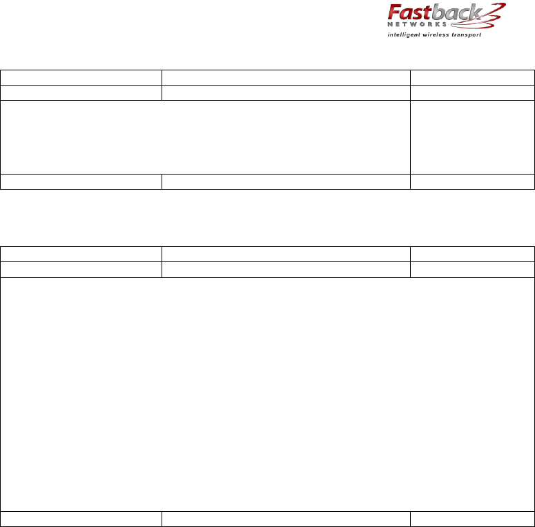
6.3.2 Fastback Networks’ Articulating Bracket - The articulating bracket has the advantage that it
can be rotated in both horizontal and vertical planes, even when affixed to a wall. The
diagram below is a guide for assembling the articulating mount and attaching it to IBR.
IBR Installation Guide
Page 21 of 32 Doc # 770-00001-3
Aug. 30, 2013
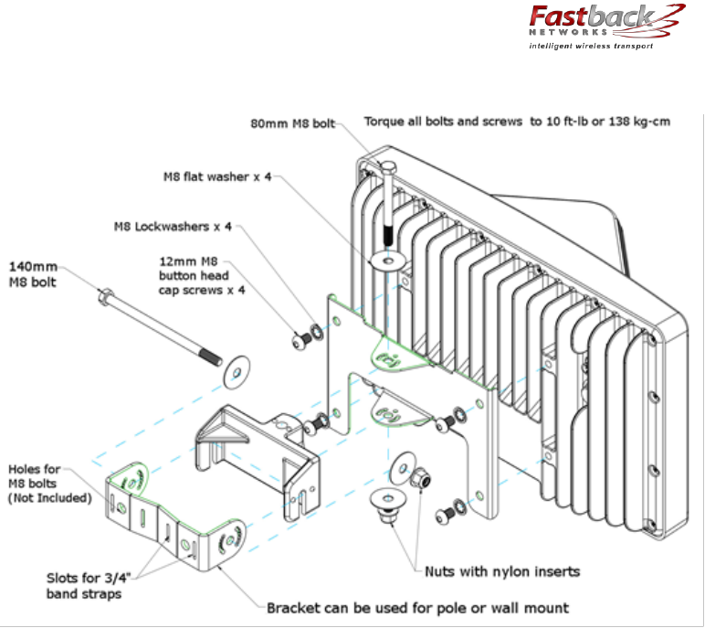
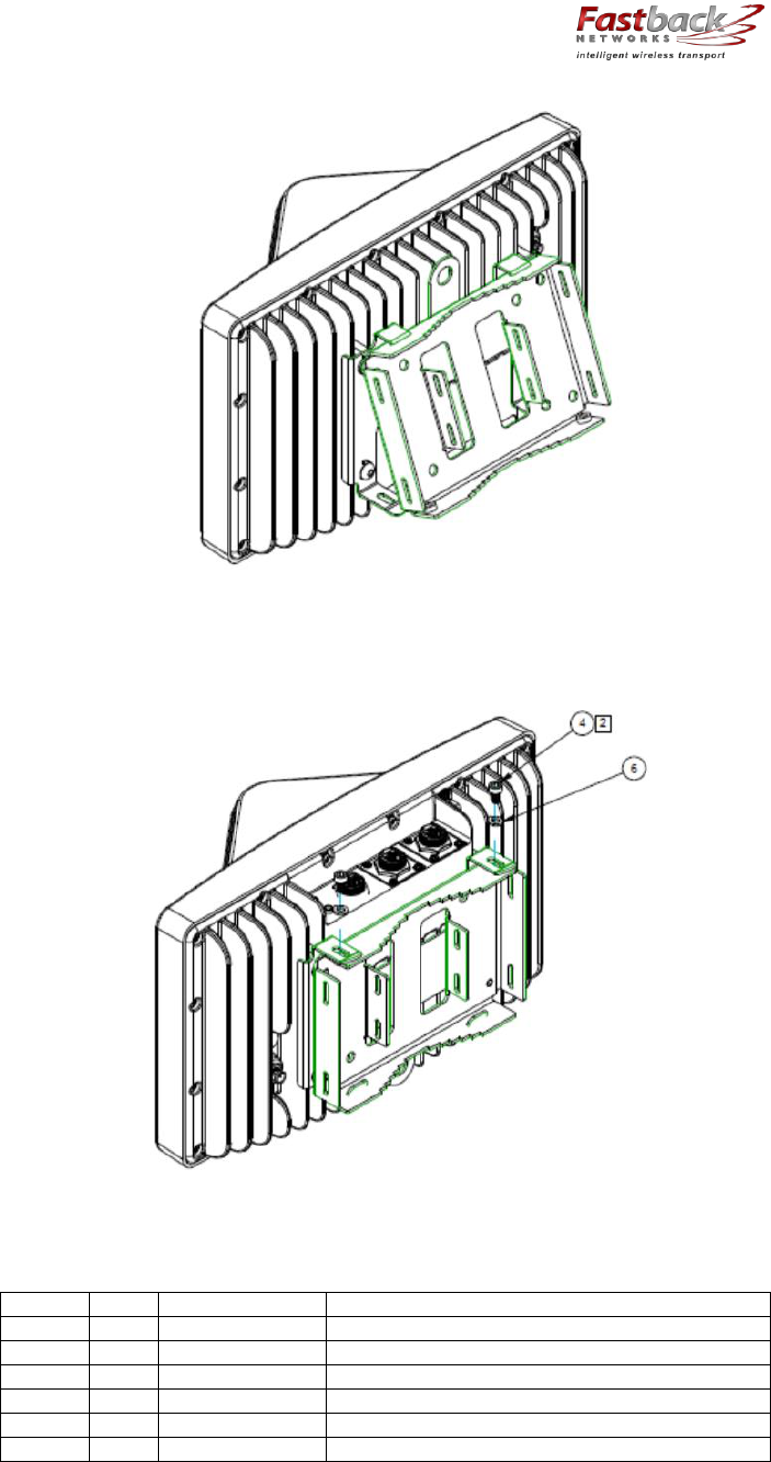
6.3.3 Fixed or Non-articulating Bracket – The fixed bracket can be rotated in the horizontal plane
when mounted to a pole, but cannot be rotated in any direction when mounted on a wall. The
following diagrams are a guide for assembling the non-articulating mount and attaching it to
IBR.
(1) Attach the IBR plate to IBR as shown below. Screws # 3 should be torqued to a
maximum of 10 ft-lbs (138 kgf-cm).
IBR Installation Guide
Page 22 of 32 Doc # 770-00001-3
Aug. 30, 2013
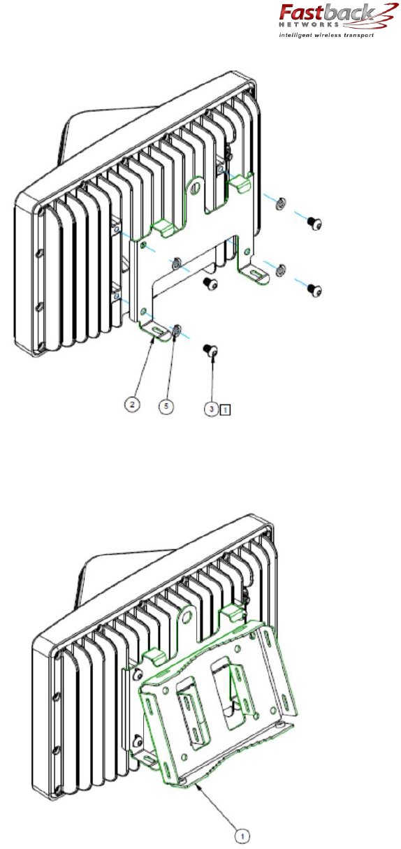
(2) Attach the pole bracket to the plate on IBR using the hooks as shown in the next two
diagrams. NOTE: If IBR will be attached to a wall, the pole bracket should be turned so
that the pole side faces IBR and the flat side faces outward.
IBR Installation Guide
Page 23 of 32 Doc # 770-00001-3
Aug. 30, 2013
(3) Use screws to secure the two plates together as shown below. Screws #4 should be
torqued to a maximum of 5 ft-lbs (69 kgf-cm). (NOTE: IBR is shown inverted from the
way it should be mounted.)
(4) Materials provided with this mount are shown in the table below.
ITEM #
QTY
PART #
DESCRIPTION
1
1
430-00014
Bracket, IBR Pole/Wall Mount, Wall Plate
2
1
430-00016
Bracket, IBR Pole/Wall Mount, IBR Plate
3
4
470-00007
Screw, M8x1.25mm, SS, Button Head
4
2
470-00008
Screw, M6x10, SS, SHCS
5
4
495-00001
Washer, M8, SS, Split Lock
6
2
495-00002
Washer, M6, SS, Split Lock
IBR Installation Guide
Page 24 of 32 Doc # 770-00001-3
Aug. 30, 2013
6.4 Connecting Power & Ethernet
When IBR has been securely mounted, connect a PoE+ source to Port 0. The power indicator
LED will turn green when power is applied. If the PoE+ source is also connected to an
Ethernet source, data will flow through IBR’s Ethernet Port 0.
If the power indicator LED does not illuminate when the power connection is made, consider
the following:
o Is the PoE connection secure?
o Is the power source receptacle hot?
o Are the cables of the proper type (CAT5E or CAT6)?
o Are the cables in good working order? (Cables should be certified.)
o Is the power brick good?
o Is the IBR working properly?
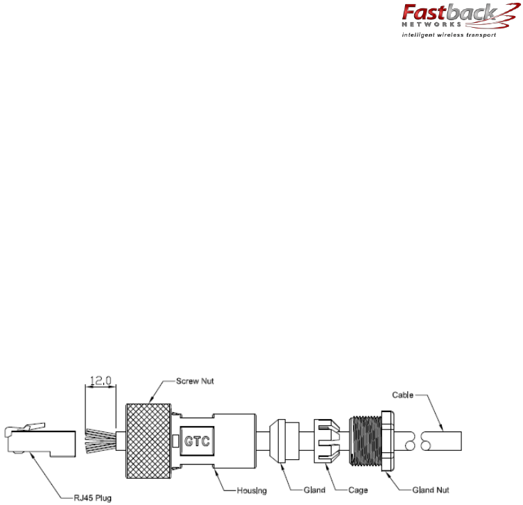
The RJ-45 Ethernet connectors on IBR will mate with the GT225360-00 connector from GT
Contact Co. LTD. An exploded view of the connector is shown below.
The connector will work with CAT5E and CAT6 cables and other cables having an
outer diameter between 5.0 and 6.0 mm. NOTE: Use only weatherproof, shielded
cable.
To assemble the connector:
o Strip the cable jacket 12.0 mm.
o Thread the cable through the connector components in the order shown.
o Insert the cable strands into the RJ-45 plug until tight.
o Assemble the connector, tightening the gland nut to within 9.0 – 10.0 kgf-cm2.
Three (3) Ethernet connectors ship with each IBR. Additional connectors may be obtained
from Fastback or directly from the manufacturer:
Model: GT225360-00
Supplier: GT Contact Co. LTD.
6.5 Connecting The Serial Port (Optional)
A local operator can communicate with IBR by connecting a suitable device to the four-pin
serial console connector on back of IBR. (See the section titled “Serial Console”.)
A local operator can configure IBR by connecting the Fastback-supplied serial cable to a PC
with a DB-9 RS-232 connection. If such a connection is not available, a USB-to-serial
converter may be used.
NOTE: When the serial port is not in use, a weatherproof protective cover should be installed
over the serial connector on IBR.

IBR Installation Guide
Page 25 of 32 Doc # 770-00001-3
Aug. 30, 2013
6.6 Establishing A Link
Except in the most severe cases of in-band interference, a pair of IBR’s will automatically
select the best combination of channel frequencies and bandwidth for a link.
(a) Wait for radios to finish booting and establishing a link.
(b) Use the CLI command shown below to verify that a link has been established.
IBR58 (config) # show interfaces radio 0 status
If a link is not automatically established within ten minutes , then consider the following
troubleshooting suggestions:
o Check to ensure that the other IBR on the link is operational.
o Change the direction in which the IBR is pointed.
o Change the IBR’s elevation.
o Determine if the link is too long for the environment.
6.7 IAS - Link Interference Analysis
IAS is a tool that IBR uses to analyze interference levels in receive channels and to select a
combination of channels and bandwidths that maximize throughput while minimizing the
effects of interference. The operator can display IAS data by executing the following
command.
IBR58 # show interface radio 0 ias
This command will return a table of data that shows the interference level in each receive
channel as received by each internal IBR antenna. The table below shows a partial output for
a 5.8 GHz radio (receives at 5.3 GHz).
ANT1 ANT2 ANT3 ANT4 ANT5 ANT6 ANT7 ANT8
Ch-5250: -90 -90 -91 -89 -88 -89 -88 -89
Ch-5251: -90 -90 -91 -89 -88 -89 -88 -89
Ch-5252: -89 -89 -88 -88 -87 -87 -85 -85
Ch-5253: -85 -86 -83 -84 -82 -82 -79 -79
7. Features & Functionality
7.1 Communication Protocols
IBR can be managed by an operator using:
o CLI: SSH, Telnet, Serial Console
o SNMP
7.2 Software Management
o Software upgrades to IBR can be made by an operator.
o Boot loader recovery can be accomplished by an operator via CLI.
o IBR has the ability to recover on its own from a failed software upgrade.
7.3 SNMP
IBR supports SNMP
10
agents using protocols v1 and v2c.
10
Simple Network Management Protocol

IBR Installation Guide
Page 26 of 32 Doc # 770-00001-3
Aug. 30, 2013
The SNMP agent will support MIB-II (RFC 1213), IF-MIB
11
(RFC 2863), and a Fastback
enterprise MIB. Detailed information for configuring SNMP is contained in the CLI Guide.
IBR sends traps supported by Fastback MIB, DISMAN-EVENT-MIB, and NET-SNMP-MIB.
SNMP polling for traps takes up to sixty (60) seconds.
7.4 Switching & Transport
IBR supports 802.1Q (VLAN).
7.5 Data Handling
IBC supports the following OSI
12
Layer 2 standards:
o IEEE 802.3ab (Gigabit Ethernet);
o IEEE 802.3as (frame expansion);
o IEEE 802.1Q (VLANs).
In addition, IBR supports port mirroring to monitor port traffic.
7.6 Carrier Ethernet
IBR conforms to the following MEF
13
specifications:
o MEF 9 – Abstract Test Suite for Ethernet Services at the UNI
o MEF 14 – Abstract Test Suite for Traffic Management Phase 1
o MEF 19 – Abstract Test Suite for UNI Type 1
7.7 Timing & Synchronization
IBR’s system clock starts when IBR is powered up and maintains time and date based on
Universal Time Coordinated (UTC), also known as Greenwich Mean Time (GMT). The system
clock can be set over the network via NTP.
Detailed instructions for configuring IBR timing and for displaying system time and date are
contained in the CLI Guide.
7.8 Network Time Protocol (NTP)
NTP runs over User Datagram Protocol (UDP), which runs over IP. It is very efficient and
typically requires no more than one NTP packet per minute to synchronize IBR’s system
clock to within one millisecond of the NTP server’s clock.
When IBR is configured to receive NTP packets from another network device, the
relationship between IBR and that device is called an “association” and it is a server
relationship, meaning that IBR will synchronize to the other device (the “server”) and the
other device will not synchronize to IBR.
By default, NTP is disabled on IBR, no NTP associations are defined, and the NTP daemon is
not running. Procedures for enabling and configuring NTP are contained in the CLI Guide.
When IBR is running NTP, IBR can be associated with more than one NTP server. Normally,
IBR will synchronize to the associated NTP server that has the lowest stratum number; that
is the lowest number of hops between the server and its clock source. A stratum 1 time
server has a radio or atomic clock directly attached, a stratum 2 time server receives its time
through NTP from a stratum 1 time server, etc.
11
MIB refers to Management Information Base, of which there are several versions
12
Open Systems Interconnection
13
Metro Ethernet Forum

IBR Installation Guide
Page 27 of 32 Doc # 770-00001-3
Aug. 30, 2013
IBR will avoid synchronizing to a server whose time might not have been synchronized or to
one whose time is significantly different than the time from other associated servers, even if
its stratum is lower.
When NTP is enabled on IBR, NTP time will take precedence over time provided by any other
source or method.
7.9 System Message Logging
IBR sends the output of system messages and certain Privileged commands to a logging
process that can be configured to distribute such messages to a logging file, remote syslog
server, or operator’s console. Detailed instructions for configuring message logging are
contained in the CLI Guide.
7.10 Quality of Service (QoS) & Class of Service (CoS)
IBR supports QoS packet prioritization in compliance with IEEE 802.p. By default, QoS is
disabled and must be configured and enabled by an operator using the commands and
procedures described in this section.
IBR’s CLI has commands that allow an operator to create and configure Traffic Classes and
Traffic Policies that are associated with specified IBR interfaces. The CLI Guide contains
detailed information for configuring QoS/CoS features.
7.11 Security
Security features of IBR include:
o AES encryption on over-the-air links;
o Access control lists;
o Multicast and broadcast storm control;
o Port protection and blocking
7.12 Electromagnetic Interference (“EMI”) Abatement
IBR is compliant with and certified to the applicable portions of the FCC Part 15 class B
(EMI).
IBR Installation Guide
Page 28 of 32 Doc # 770-00001-3
Aug. 30, 2013
Appendix A – IBR Mounting Brackets
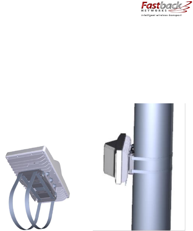
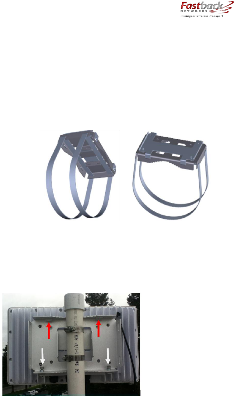
A 1. Wall/Pole Mounting Bracket
Fastback Networks’ wall/pole mounting bracket assembly can be used to mount IBR on poles, on
the sides of buildings, or in other outdoor locations. The first illustration below shows a fully
assembled bracket with pole straps attached to IBR, and the second illustration shows IBR
mounted on a mast using the same bracket.
1.1. Ordering Information
The Wall/Pole Mounting Bracket Assembly consists of the following components:
o IBR mounting plate
o Four M8x12 bolts for attaching IBR to mounting plate
o Wall/Pole mounting plate
o Two M6x10 bolts for attaching the two plates to one another
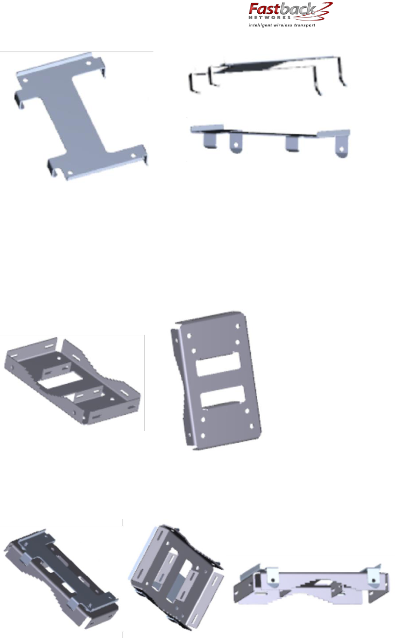
1.2. IBR Mounting Plate
The plate shown below attaches directly to the mounting lugs on IBR. This plate should be firmly
mounted to IBR before IBR is raised to its mounting location. Four bolts, size M8 x12, with lock
washers are required to mount this bracket to IBR.
The raised edges on the top side of the plate mate with the heat sinks on IBR. The plate attaches
to the wall/pole plate via hooks on one side and two bolts, size M6x10, with lock washers on the
other side.
IBR Installation Guide
Page 29 of 32 Doc # 770-00001-3
Aug. 30, 2013
1.3. Wall/Pole Plate
The plate shown below attaches to the IBR mounting plate for mounting IBR on a pole or mast
that is between one and six inches in diameter, or on a wall or other structure.
When IBR will be mounted on a wall, the flat side of this plate will be against the wall. When IBR
will be mounted on a mast, the flat side of this plate will be against the IBR mounting plate.
1.4. How The Plates Attach To One Another
The illustrations below show how two plates attach to one another in a pole mount configuration.
IBR Installation Guide
Page 30 of 32 Doc # 770-00001-3
Aug. 30, 2013
1.5. Pole mounting straps
Mounting IBR on a pole or mast simply requires attaching pole bands to the bracket as shown
below. Be careful to not damage the bracket when tightening the bands.
Pole straps can be attached either to the ends of the plate or to the flanges in the center of the
plate as appropriate for the diameter of the mast to which it is being attached.
Pole bands are not included. The bracket will accept steel bands up to ¾” wide.
1.6. Mounting Instructions
When the mounting plate has been affixed to IBR and the wall/pole plate has been mounted in its
permanent location, the last step is to hang the IBR onto the mounting plate by first inserting the
tabs on the top of the IBR mounting plate into the slots at the top of the wall/pole plate shown by
the red arrows in the figure below. Finally, mate the two plates together and secure using two
M6x10 bolts shown by the white arrows in the figure below.
IBR Installation Guide
Page 31 of 32 Doc # 770-00001-3
Aug. 30, 2013
The installer can attach a rope or hook to one of the holes on the side of the mounting bracket in
order to hang IBR on a utility belt until it is time to attach it to the bracket. To aid in hanging IBR,
the plate on IBR can be hooked onto the mating wall/pole plate while the two M6x10 mounting
bolts are being tightened. An Allen wrench is needed to tighten the bolts.
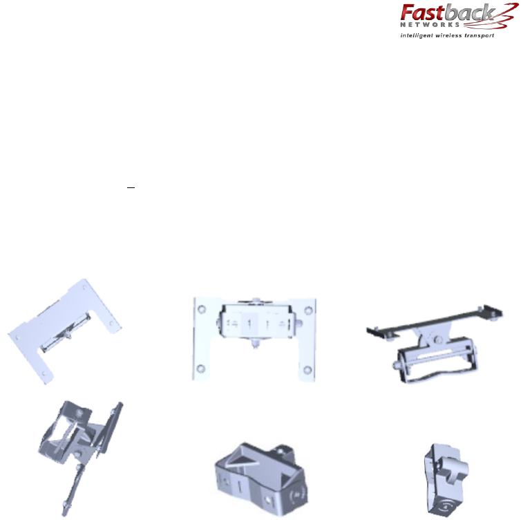
A 2. Articulating Mount
Fastback Networks offers an articulating mount that be mounted on walls or masts and which
can be adjusted up to + 45 degrees in elevation and azimuth in 15 degree increments. Like the
Wall/Pole Mount, the Articulating Mount has a plate that attaches to IBR and a part that attaches
to the wall or mast. An articulating knuckle provides the freedom of movement.
The images below show the Articulating Mount and its components from several angles.
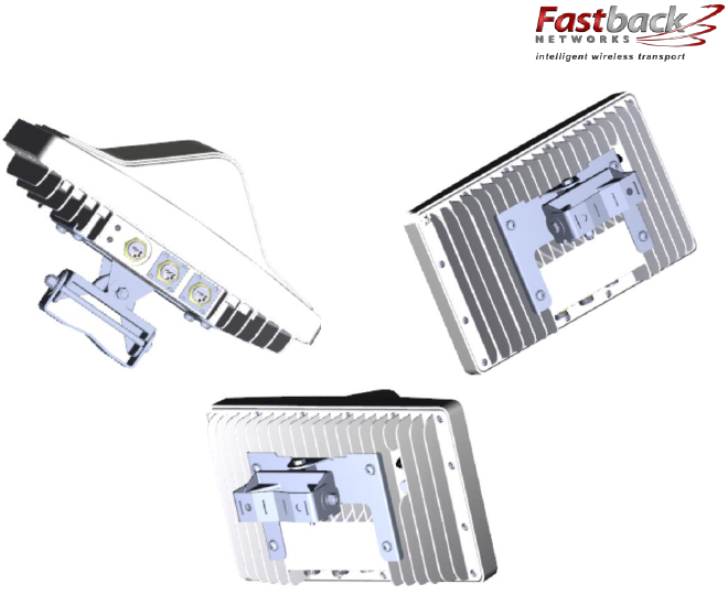
The images below show the Articulating Mount attached to IBR.
IBR Installation Guide
Page 32 of 32 Doc # 770-00001-3
Aug. 30, 2013