Skyline Partners Technology Fastback Networks 105 Intelligent Backhaul Radio User Manual IBR Installation Guide
CBF Networks, Inc., dba Fastback Networks Intelligent Backhaul Radio IBR Installation Guide
UserManual.wiki
>
Skyline Partners Technology Fastback Networks
>
105 User Manual
Installation Guide
Navigation menu
Upload a User Manual
Namespaces
Wiki Guide
HTML
PDF
Info
Views
User Manual
Discussion / Help
Navigation
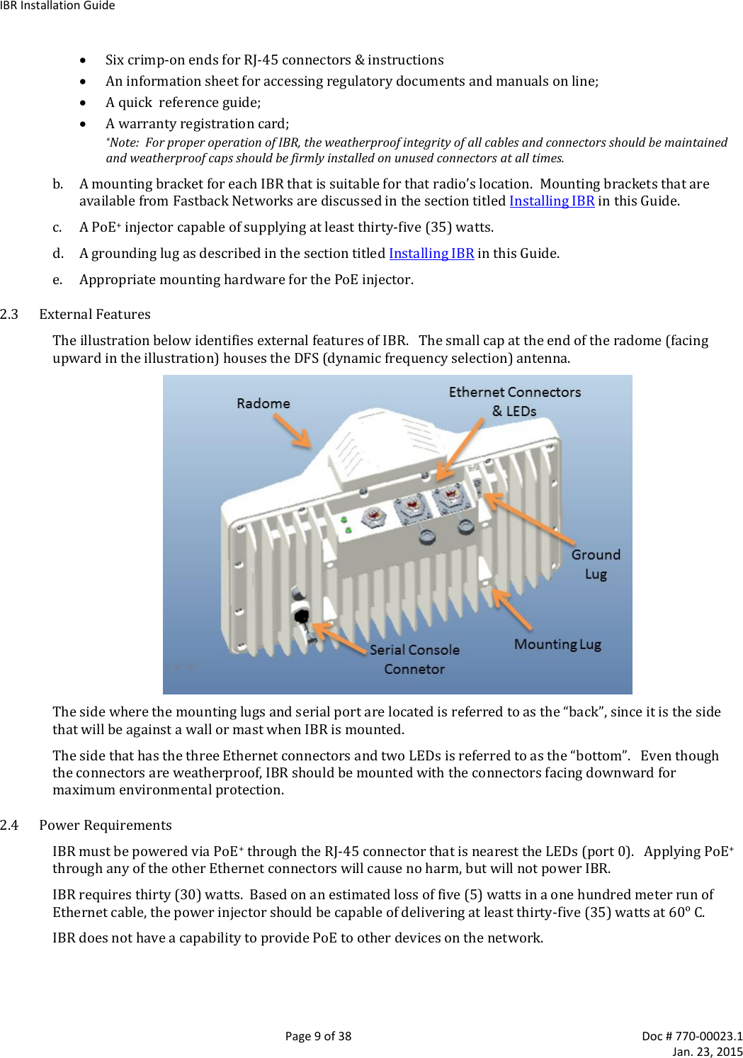
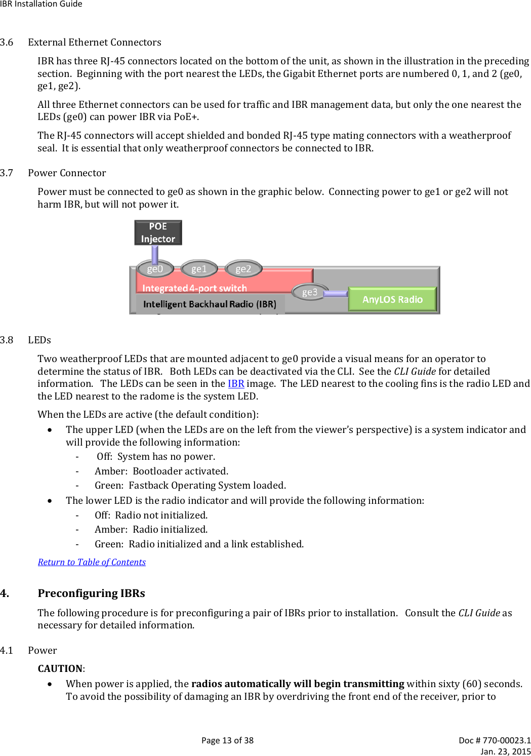
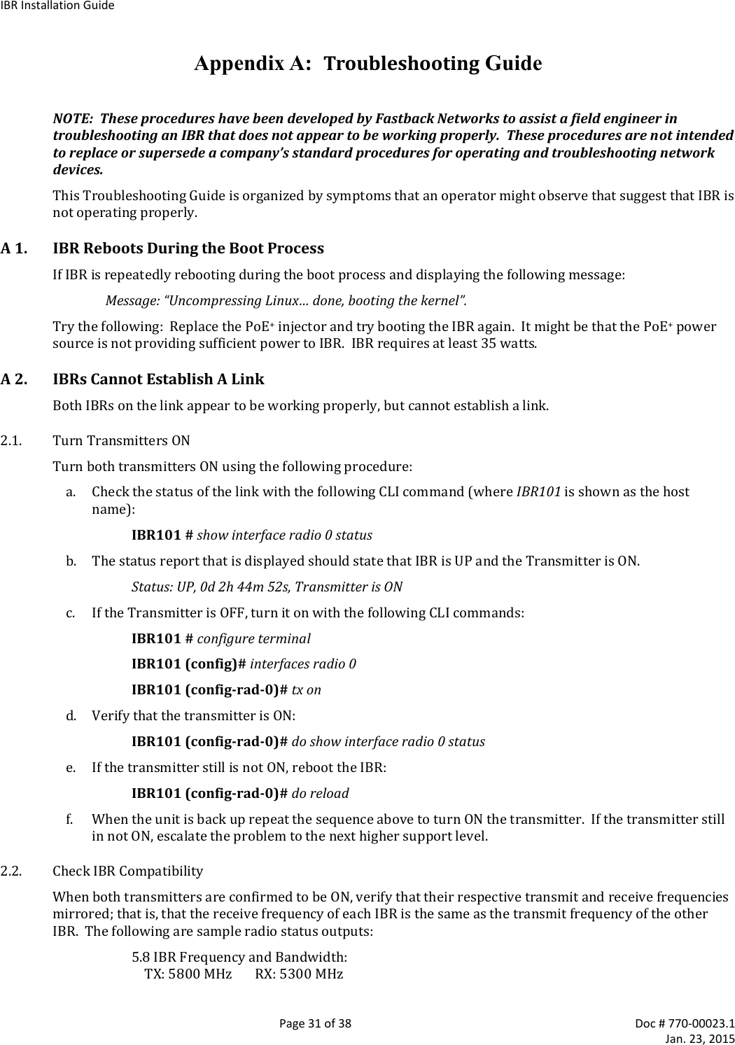
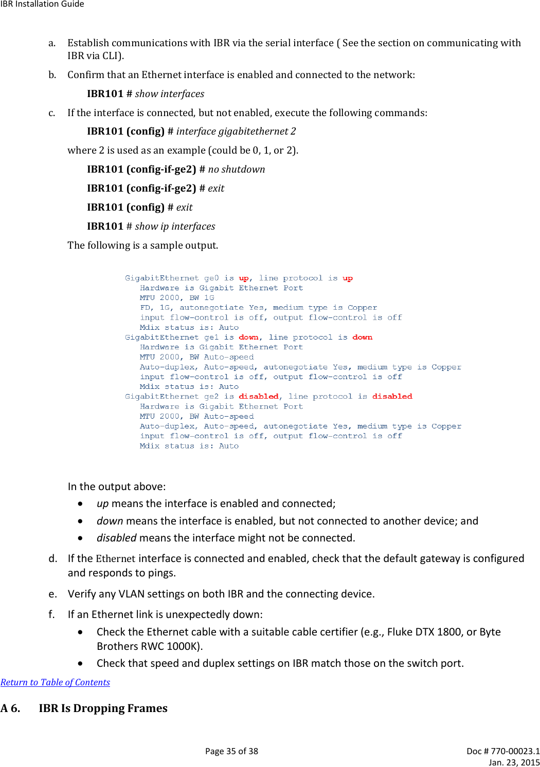
![IBR Installation Guide Page 14 of 38 Doc # 770-00023.1 Jan. 23, 2015 connecting a power source, position the two IBRs so that they are tilted away from each other, facing downward, and separated by at least one meter. IBR does not have a power on/off switch, either in hardware or software. When power is applied to the unit, IBR will be in a “power on” condition and the system LED beside the ge0 port connector will be illuminated. Apply power to each IBR using a PoE+ source connected to Gigabit Ethernet interface 0. Although PoE+ sources can be applied harmlessly to any port, only ge0 can be used to power IBR. 4.2 CLI Privileged Mode Enter Privileged mode by entering the enable command: IBR102 > enable The factory-set password for entering Privileged mode is fastback. The Privileged Mode command prompt, with IBR102 as host name will be: IBR102 # The following CLI commands are available in Privileged mode. Privileged Mode Commands Command Description IBR102 # ! Comments clear Reset functions alarms Clear alarm history config Reset to factory defaults counters Clear counters on one or all interfaces configure terminal Enter Global Config mode to manage device parameters copy Copy a file (e.g., running-config) ethernet Ethernet subcommands exit Return to User Mode ping [string] Send messages to network hosts [hostname or IP address] reload Halt & perform a cold restart show Show running system info (see CLI Guide for a complete list of show cmds) telnet IP address or hostname of a remote system traceroute Print the route packets trace to network host ip IPv4 ipv6 IPv6 [string] Hostname or IP address to trace the route upgrade Upgrade commands http Upgrade http (enter A.B.C.D [/mask] or any http server IP address) sftp Upgrade sftp (enter A.B.C.D [/mask] or any sftp server IP address) tftp Upgrade tftp (enter A.B.C.D [/mask] or any tftp server IP address) For a detailed discussion of CLI commands, refer to the CLI Guide. 4.3 RSL Check the RSL on each IBR using the following CLI command in the Privileged mode: IBR102 # show interface radio 0 status RSL should be -36dBm or less. If RSL is greater than -36 dBm (e.g., -30dBm) on either IBR, the received signal level is too high and greater separation of the IBRs is recommended to avoid receiver saturation. 4.4 Management Traffic IBR interfaces should be configured in such a way as to separate internal management traffic from user data traffic (i.e., prevent management traffic from being sent over the network). The following sequence of](https://usermanual.wiki/Skyline-Partners-Technology-Fastback-Networks/105/User-Guide-2514489-Page-14.png)
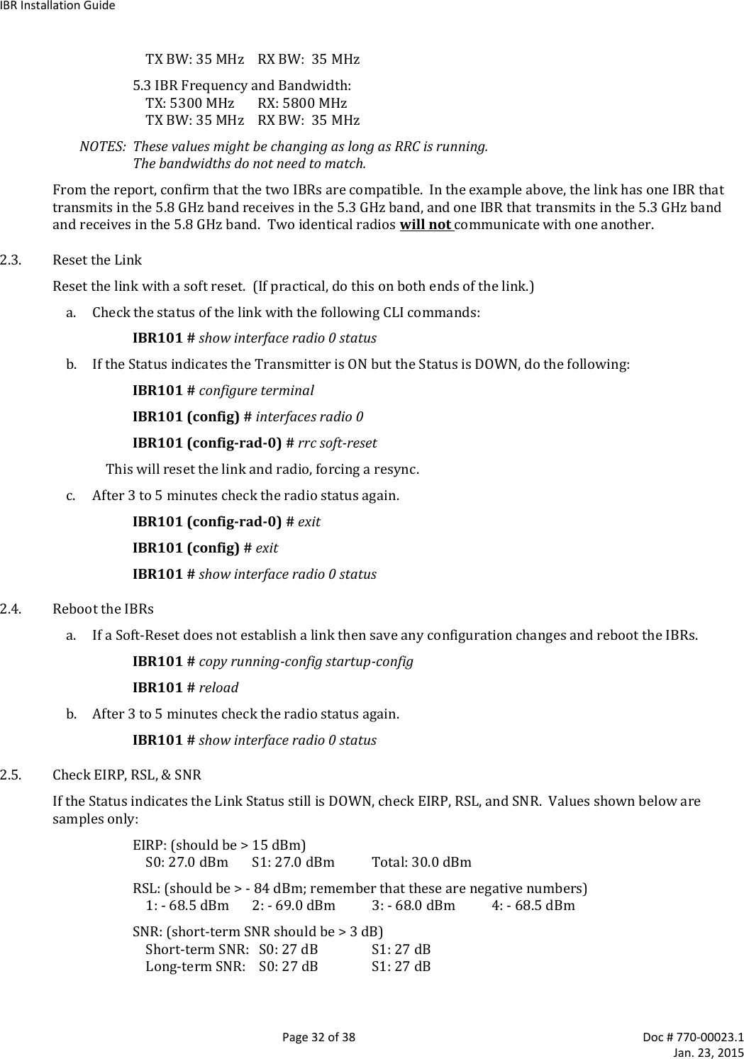
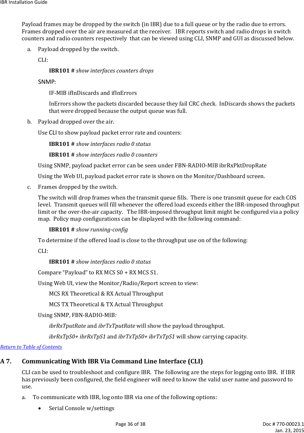
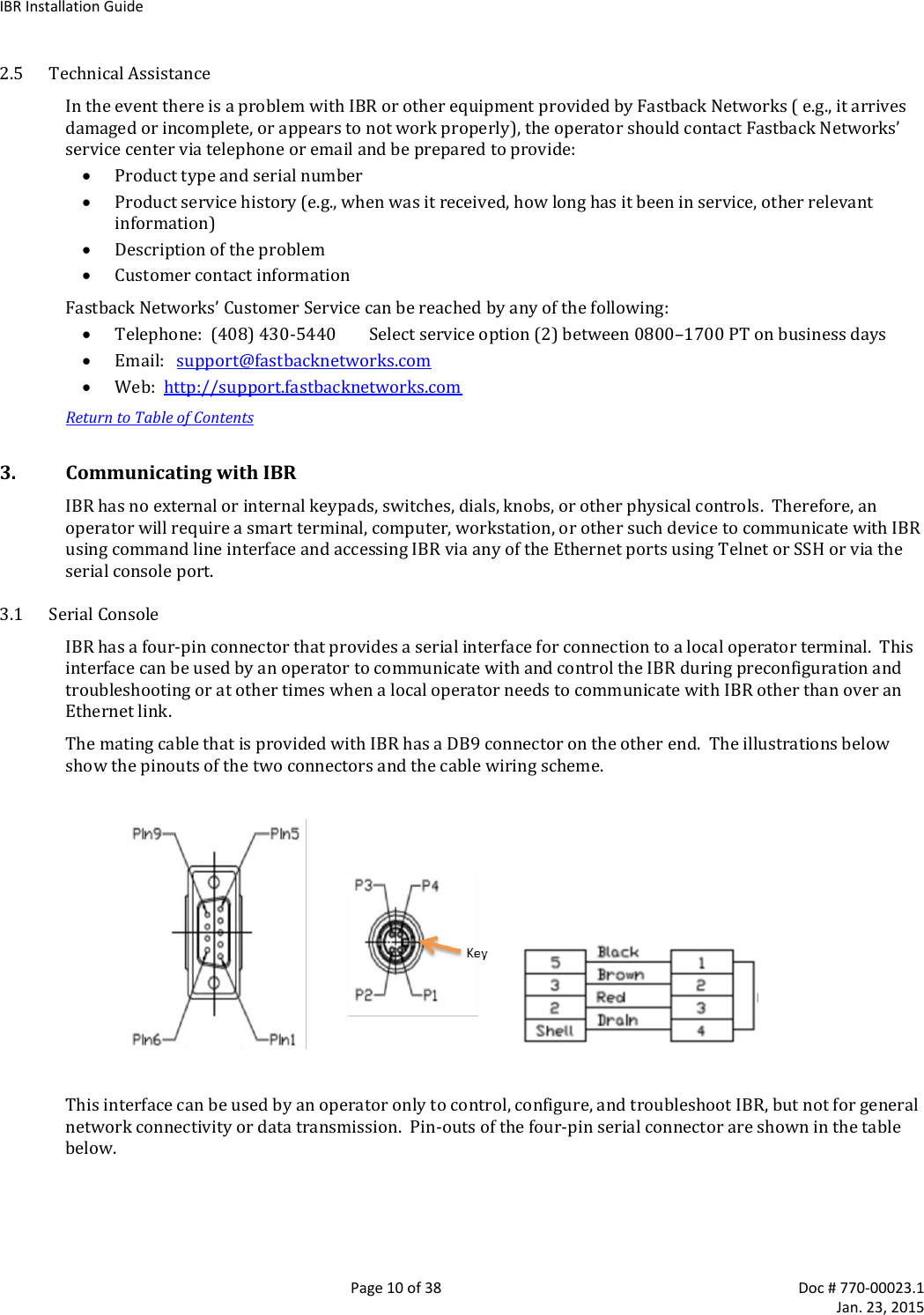
![IBR Installation Guide Page 17 of 38 Doc # 770-00023.1 Jan. 23, 2015 GigabitEthernet ports 1 and 2 are physical ports allowing connections to the provider network. GigabitEthernet 3 is dedicated to the IBR RF link and creates a wireless bridge between two network segments. c. eth0.823 is an isolated debug interface on VLAN 823. VLAN823 will allow traffic only to be sent from one IBR to the other across the wireless link and requires that the sender be logged onto one of the IBRs. One use of this interface is to allow a user to send ping packets to the opposite IBR to verify link integrity. This VLAN has no exposure to a physical network interface so traffic on this VLAN is isolated from the network. Another important use of this configuration is to manage the link partner from the local IBR. 4.4.8 Save the New Configuration. Use the following commands to save the new settings to the startup configuration file. IBR102 # copy running-config startup-config 4.5 Host Name Change the host name (optional) using the following command in Global Config mode. IBR102 (config) # hostname [newname] 4.6 User Names & Passwords IBR can be configured to require valid user names and passwords for access to CLI User Mode, CLI Privileged Mode, and the GUI. Each user name and password will be independent of the others. Passwords are stored permanently in IBR and are not part of the startup-config or running-config files. Passwords will be displayed in encrypted form in the show running-config output. Passwords are strings of at least six and not more than sixteen characters and can include any letter, any numeral, and any of the following symbols: ! @ $ % 4.6.1 CLI User Mode - IBR can be configured to recognize individual user names, each with its own password. The command to configure User Mode user names and passwords is: IBR102 (config) # username [user_id] password [newpassword] If the password of an existing user is being changed, user_id will be the user name (or ID) of the existing user and newpassword will be the newly assigned password. If a new user is being created, user_id will be the new user name and newpassword the assigned password for that user. The command to remove an existing user name is: IBR102 (config) # no username [user_id] where user_id is the name of the user that is being removed. The factory-set user name is fbn and the password is fastback. The factory-set user name (fbn) cannot be changed or deleted, but the password for fbn can be changed using either of the following commands: IBR102 (config) # username fbn password [newpassword] or IBR102 (config) # enable password level 1 [newpassword] where newpassword is the newly assigned password.](https://usermanual.wiki/Skyline-Partners-Technology-Fastback-Networks/105/User-Guide-2514489-Page-17.png)
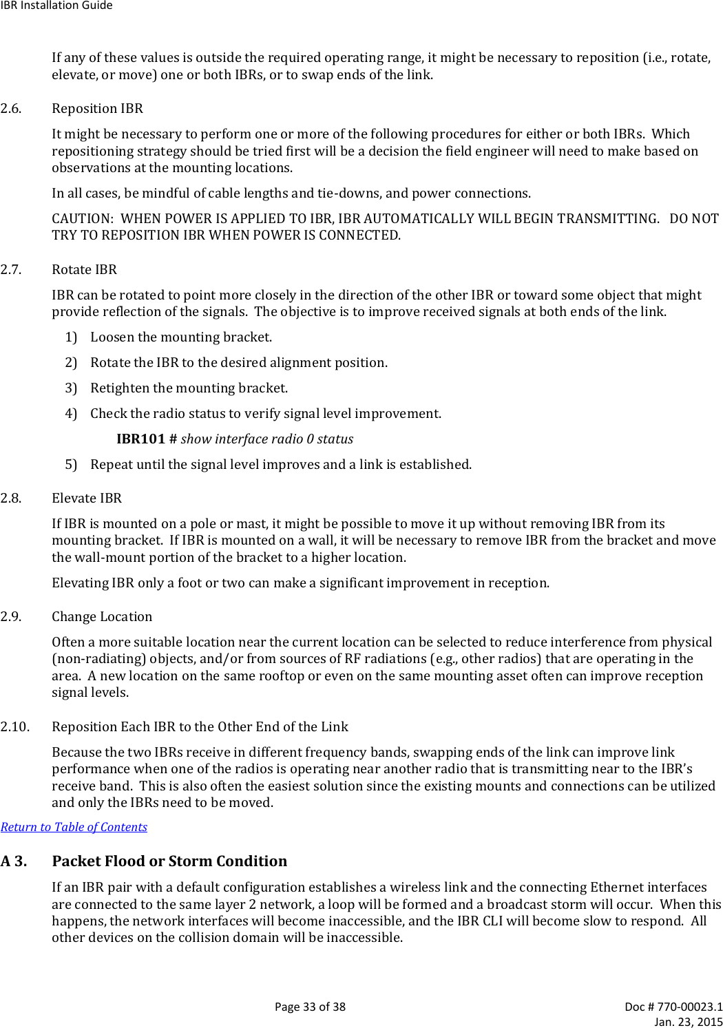
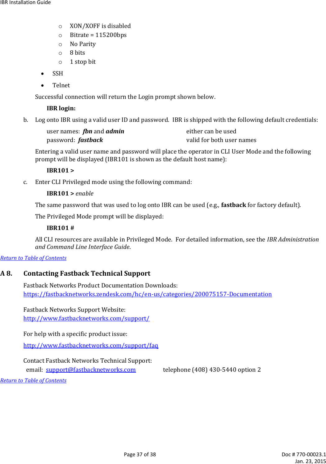
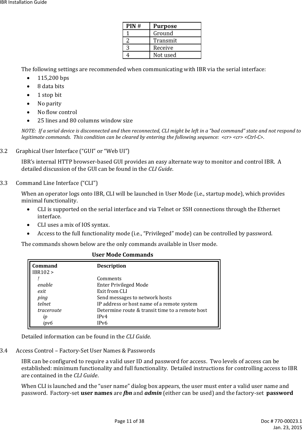
![IBR Installation Guide Page 18 of 38 Doc # 770-00023.1 Jan. 23, 2015 4.6.2 CLI Privileged Mode – Privileged Mode can be entered only from User Mode and can be protected with a single password for all users. The requirement to use a password to enter Privileged Mode can be enabled or disabled from the Privileged Mode as follows: IBR102 (config) # enable password {level (1-15)} [newpassword] where level must either be the number 1 or the number 15 and newpassword is the newly assigned password. When level = 1, the password for the user named fbn will be changed. When level = 15, the password to enter Privileged Mode will be affected. When no level option is entered, Privileged Mode will be affected. The requirement for a user to enter a password to move from User Mode to Privileged Mode can be disabled using the following command; however, this is not a recommended configuration because it can create security problems: IBR102 (config) # no enable password The following are examples of commands for creating, changing, or disabling passwords. Setting Passwords Command Description IBR102 (config) # enable password level 1 fastbackuser Set PW as fastbackuser for the user named fbn enable password level 15 fastb@ckuser Set the PW for all users to enter Privilege Mode as fastb@ckuser enable password fast$$$user Set the PW for all users to enter Privilege Mode as fast$$$user no enable password level 1 Remove the requirement for fbn to use a PW to enter User Mode no enable password level 15 Remove the requirement for all users to use a PW to enter Privileged Mode no enable password Remove the requirement for all users to use a PW to enter Privileged Mode 4.6.3 Web Graphical User Interface (GUI) – User names and passwords for the GUI are managed independently from CLI user names and passwords. For additional information, see the GUI section of the CLI Guide. 4.7 Password Recovery & Reinstating IBR Default Settings In the event that users cannot gain access to IBR because passwords have been forgotten, the following procedure can be used to reset all IBR settings to their default values, thereby allowing a user to regain access to IBR. This procedure will boot IBR into a Linux root shell single-user mode where the user can change the Privileged Mode password. Initiate a system reboot and, within two (2) seconds, press Ctrl C to interrupt the reboot process. Enter the following command when the uMON> prompt is displayed5: uMON> run flash linuxsingle The system will take several minutes to reboot. When the Linux prompt is displayed, enter the command password root and then respond to the succeeding prompts to change the Privileged Mode password and reboot the system by entering the command reboot. When IBR reboots to CLI User Mode, use the default user name and password to log onto the system. Use the new Privilege Mode password to enter Privilege Mode. Then follow the standard procedure to change the User Mode user name and password. Note: To interrupt an ongoing reboot, interrupt power to IBR. 4.8 System Clock The command to set the IBR system clock is executed in Global Config mode and has the following form. 5 This works only with a serial console connection.](https://usermanual.wiki/Skyline-Partners-Technology-Fastback-Networks/105/User-Guide-2514489-Page-18.png)
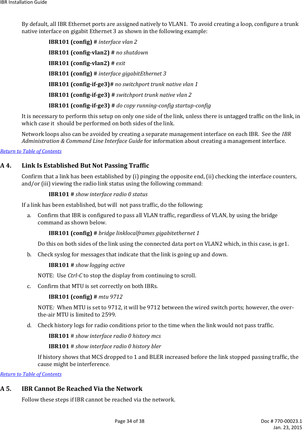
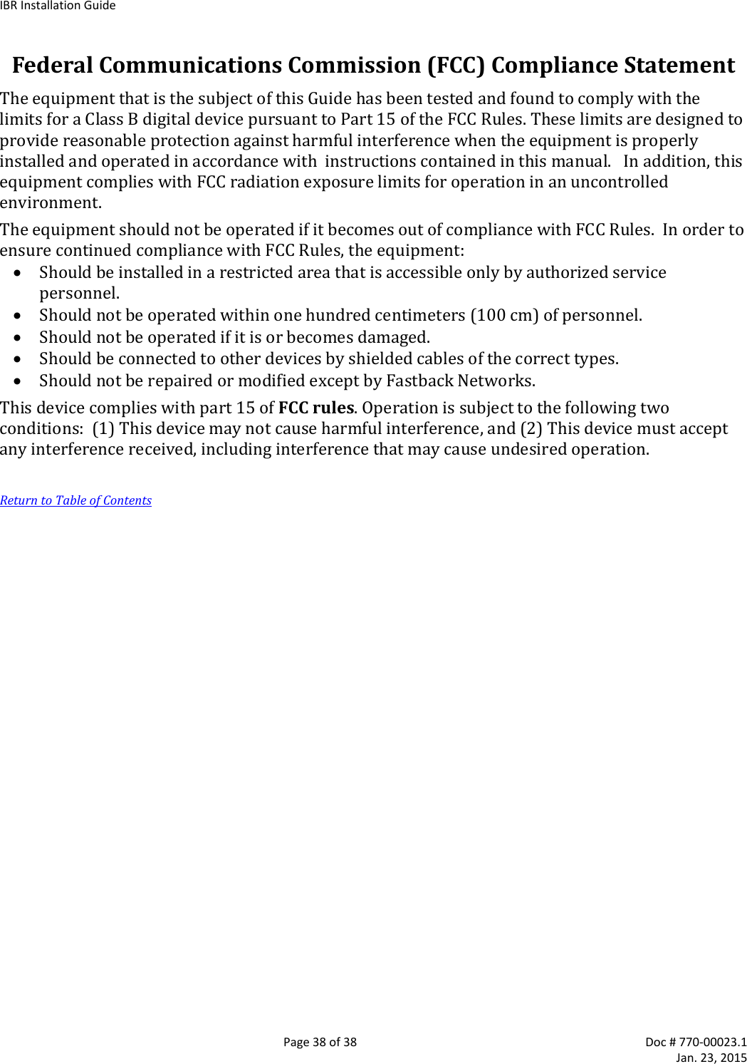
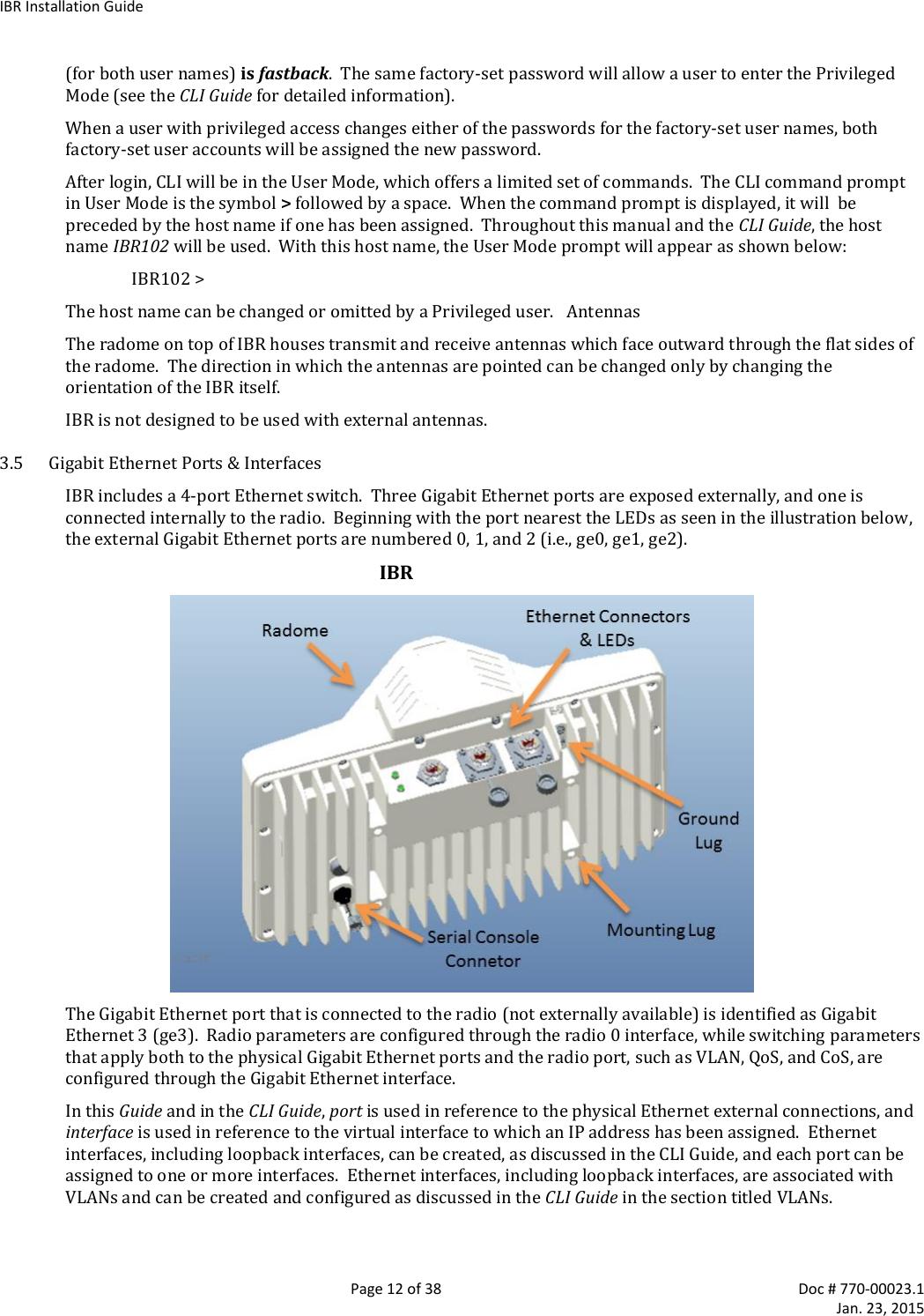
![IBR Installation Guide Page 19 of 38 Doc # 770-00023.1 Jan. 23, 2015 IBR102 (config) # clock set [hh:mm:ss] [YYYY-MM-DD] where all of the arguments are integers. 4.9 Name Server The following command can be used to configure the Name server. IBR102 (config)# ip name-server [ip-address} 4.10 NTP Server The following command can be used to configure the NTP server. IBR102 (config)# ntp server [ip-address} 4.11 SNMP Server Commands for configuring SNMP are shown in the table below. For detailed information, see the CLI Guide. Configuring SNMP Command Description IBR102 (config) # snmp-server Configure SNMP community SNMP community configuration contact Set the system contact enable Enable SNMP notification types (traps) group SNMP group configuration host SNMP trap host configuration location Set the system location trap-env Set SNMP trap environment (standard or x.733) trap-thresholds Set SNMP trap threshold values view SNMP view configuration 4.12 Link ID The command to set Link ID has the following syntax: IBR102 (config) # link-id [linkname] where linkname is an alphanumeric string from one to thirty-two characters in length that can contain any of the following symbols: ! @ # $ % - _ Using Link ID Command Prompt Command Remarks IBR102 (config) # interface radio 0 Config radio interface “0” IBR102 (config-if-rad0) # link-id 58$a2 Sets link ID to “58$a2” IBR102 (config-if-rad0) # exit Return to Global Config IBR102 (config) # 4.13 Radio Link IBRs will automatically establish a link using the best frequencies to optimize data throughput. Return to Table of Contents 5. MAC Address Table & Counters 5.1 MAC Address Table The MAC Address table, sometimes referred to as the L2 (or Layer 2) table, associates MAC addresses with their respective VLAN’s and ports.](https://usermanual.wiki/Skyline-Partners-Technology-Fastback-Networks/105/User-Guide-2514489-Page-19.png)
![IBR Installation Guide Page 21 of 38 Doc # 770-00023.1 Jan. 23, 2015 Packets TX queue packets MCS counters can be displayed using the following command: IBR102 # show interfaces radio 0 status Counters can be cleared using the following commands: IBR102 # clear counters mcs clears mcs counters IBR102 # clear counters radio clears radio counters IBR102 # clear counters switch clears counters on all switch interfaces IBR102 # clear counters gigabitEthernet [arg] arg can be 0, 1, 2, or 3 Return to Table of Contents 6. Installing IBR 6.1 Safety Considerations Ensure that grounding is in accordance with local codes. IBR should be grounded using the ground lug connector on the back of IBR with a lug such as Panduit Two-Hole Standard Barrel Copper Lug, Panduit part #LCD6-14A-L (shown below). Note that since the grounding lug mounts between the fins, any lug greater than 0.48 inches in width will not fit. Use overhead work methods and/or equipment that are appropriate for the location; e.g., climbing equipment, ladder, man lift, etc. Note the locations of other equipment, power lines, vehicle traffic, and other potential safety hazards at the installation site. 6.2 Installation Checklist for one end of a link6 A pretested and preconfigured IBR. IBR mounting brackets. A PoE+ source capable of supplying at least thirty-five (35) watts total on two pairs (pins 4&5 and 7&8) or on all four pairs. A surge suppressor that has been validated to function properly with IBR, such as Transector Model T-419899. Materials for grounding IBR: 6 A link will require a matching pair of IBRs; e.g., IBR101 and IBR102.](https://usermanual.wiki/Skyline-Partners-Technology-Fastback-Networks/105/User-Guide-2514489-Page-21.png)