Skyline Partners Technology Fastback Networks 107 Intelligent Backhaul Radio User Manual IBR Installation Guide

CBF Networks, Inc., dba Fastback Networks Intelligent Backhaul Radio IBR Installation Guide

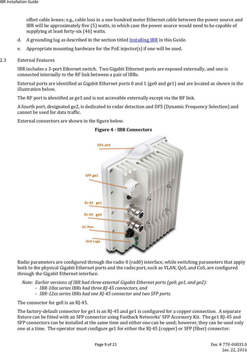
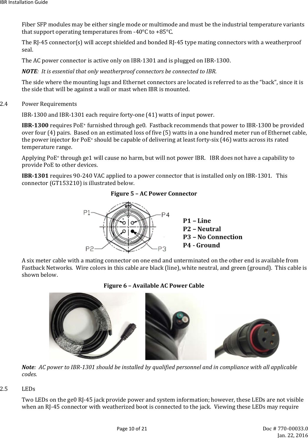
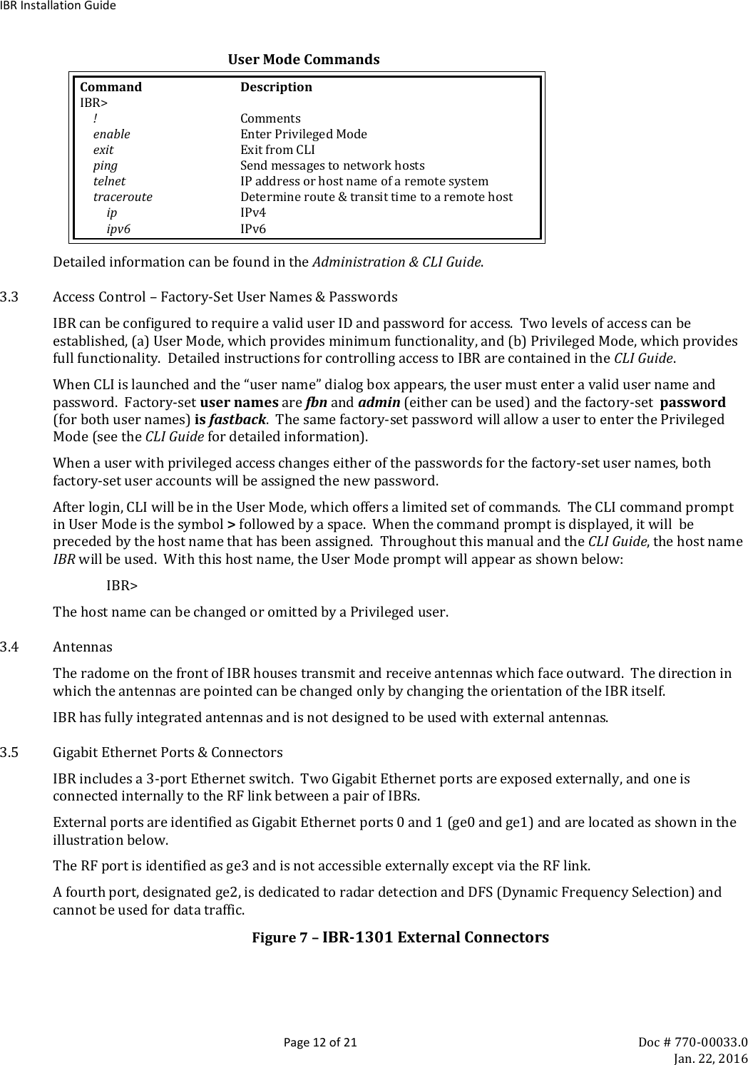
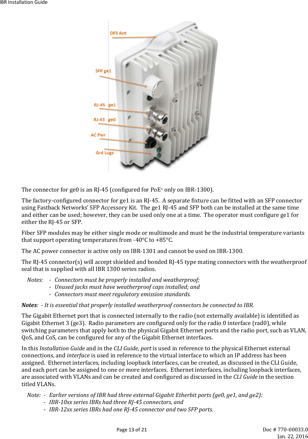
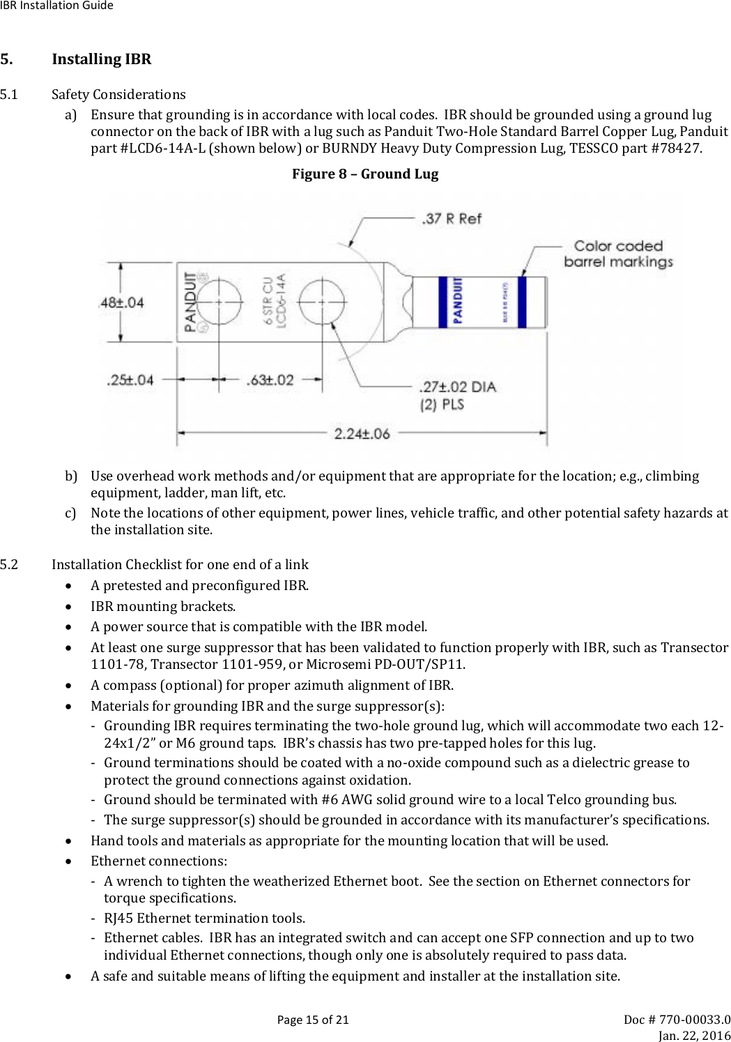
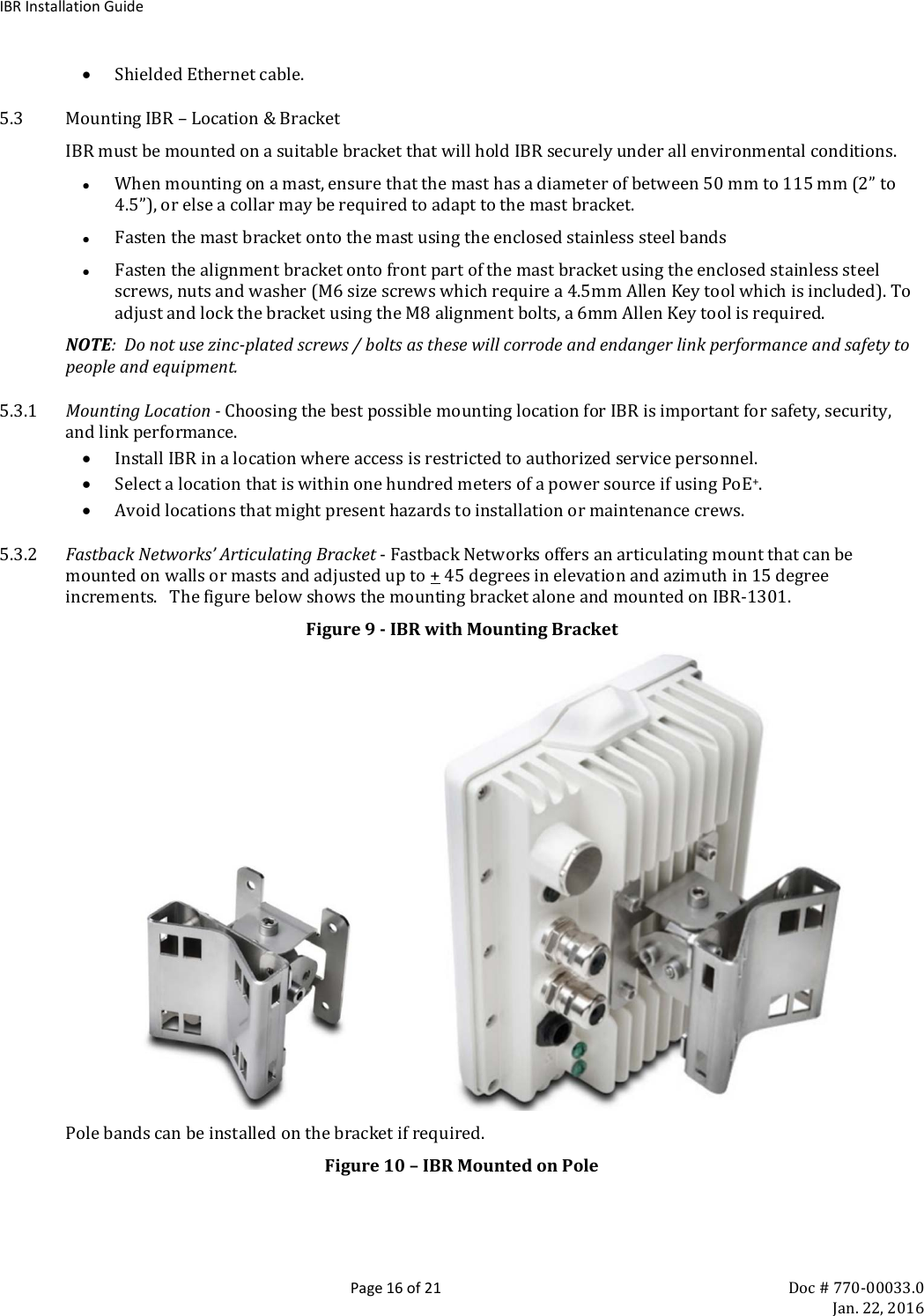
Installation Guide v1.0 1-22-16a

  2460 N First St., Suite 200, San Jose, CA 95131 U.S.A. Doc # 770-00033.0 (408) 430-5440 www.fastbacknetworks.com Jan. 22, 2016 Intelligent Backhaul Radio Administration & Command Line Interface Guide
IBR Installation Guide  Page 2 of 21 Doc # 770-00033.0     Jan. 22, 2016  Purpose & Applicability of This Guide This Guide provides detailed information related to installing, operating, and trouble-shooting Fastback Network’s Intelligent Backhaul Radio (“IBR”). This Guide provides information that is specifically applicable to the following IBR models: A. Model Number:  IBR-1300-NA Low Frequency Operating Band (Transmit & Receive):  5150 – 5350 MHz High Frequency Operating Band (Transmit & Receive):  5470 – 5850 MHz Transmit Power (Maximum):  42 dBm EIRP Powered by a PoE+ source The features contained in IBR software release 1.6.8  B. Model Number:  IBR-1301-NA Low Frequency Operating Band (Transmit & Receive):  5150 – 5350 MHz High Frequency Operating Band (Transmit & Receive):  5470 – 5850 MHz Transmit Power (Maximum):  42 dBm EIRP Powered by a 90-240 volt/60 Hz AC source The features contained in IBR software release 1.6.8   Notes: 1) In a link, one radio will transmit in the low band and the other will transmit in the high band. 2) Patent information can be found at:  www.fastbacknetworks.com/patents
IBR Installation Guide  Page 3 of 21 Doc # 770-00033.0     Jan. 22, 2016  Special Considerations and Safety Warnings  Prior to installing and operating this equipment, read all instructions and warning notices marked on the equipment or in accompanying documentation.  Do not attempt to apply power to equipment that shows signs of damage, tampering, or mishandling.  Do not open the equipment or attempt to repair or modify it.  Doing so will void the warranty and might create a safety hazard and/or cause the equipment to be out of compliance with regulations. This equipment should be installed, operated, and serviced only by qualified personnel and in a location that is accessible only by authorized service personnel. Installation and operation of this equipment should be in compliance with applicable national and local codes. Ensure that this equipment is grounded at all times in accordance with local codes.
IBR Installation Guide  Page 4 of 21 Doc # 770-00033.0     Jan. 22, 2016 Table of Contents Purpose & Applicability of This Guide  2 Special Considerations and Safety Warnings  3 Table of Contents  4 1. Introducing Intelligent Backhaul Radio (“IBR”)  6 1.1 Overview .................................................................................................................................................... 6 1.2 Factory-Set Host Name and IP Addresses .................................................................................................... 6 1.3 Deployment Options ................................................................................................................................... 7 1.4 Physical & Environmental Features ............................................................................................................. 7 2. Getting Started  8 2.1 Physical Inspection...................................................................................................................................... 8 2.2 Inventory .................................................................................................................................................... 8 2.3 External Features ........................................................................................................................................ 9 2.4 Power Requirements ................................................................................................................................. 10 2.5 LEDs.......................................................................................................................................................... 10 2.6 Technical Assistance ................................................................................................................................. 11 3. Communicating with IBR 11 3.1 Graphical User Interface (“GUI” or “Web UI”) ........................................................................................... 11 3.2 Command Line Interface (“CLI”) ................................................................................................................ 11 3.3 Access Control – Factory-Set User Names & Passwords............................................................................. 12 3.4 Antennas .................................................................................................................................................. 12 3.5 Gigabit Ethernet Ports & Connectors ........................................................................................................ 12 4. Preconfiguring IBRs 14 4.1 Power ....................................................................................................................................................... 14 4.2 Restoring Factory-Set Configuration – Reset Button.................................................................................. 14 4.3 Radio Link ................................................................................................................................................. 14 5. Installing IBR 15 5.1 Safety Considerations ............................................................................................................................... 15 5.2 Installation Checklist for one end of a link ................................................................................................. 15 5.3 Mounting IBR – Location & Bracket .......................................................................................................... 16 5.4 Power & Ethernet Connections ................................................................................................................. 17 5.5 Fabricating an Ethernet Cable ................................................................................................................... 17 5.6 Surge Suppressor Installation .................................................................................................................... 18 5.7 Link Establishment .................................................................................................................................... 19 6. Features & Functionality 19 6.1 AnyLOS Technology .................................................................................................................................. 19 6.2 Communication Protocols ......................................................................................................................... 19 6.3 Software Management ............................................................................................................................. 19 6.4 Security..................................................................................................................................................... 20 7. Field Test Procedure 20 7.1 Firmware Upgrade .................................................................................................................................... 20 7.2 RFC 2544 Traffic Tests ............................................................................................................................... 20 7.3 Endurance Test ......................................................................................................................................... 20 7.4 Traffic Classification Test .......................................................................................................................... 20 Federal Communications Commission (FCC) Compliance Statement 21  Table of Figures Figure 1 – IBR Front & Rear Views ................................................................................................................................................................................6 Figure 2 – Small Cell Site ....................................................................................................................................................................................................7
IBR Installation Guide  Page 5 of 21 Doc # 770-00033.0     Jan. 22, 2016 Figure 3 - IBR Dimensions .................................................................................................................................................................................................7 Figure 4 - IBR Connectors ..................................................................................................................................................................................................9 Figure 5 – AC Power Connector ................................................................................................................................................................................... 10 Figure 6 – Available AC Power Cable ........................................................................................................................................................................ 10 Figure 7 – IBR-1301 External Connectors .............................................................................................................................................................. 12 Figure 8 – Ground Lug ...................................................................................................................................................................................................... 15 Figure 9 - IBR with Mounting Bracket ...................................................................................................................................................................... 16 Figure 10 – IBR Mounted on Pole ............................................................................................................................................................................... 16 Figure 11 – RJ-45 Plug Assembly ................................................................................................................................................................................ 17 Figure 12 – Surge Suppressors ..................................................................................................................................................................................... 19
IBR Installation Guide  Page 6 of 21 Doc # 770-00033.0     Jan. 22, 2016 1. Introducing Intelligent Backhaul Radio (“IBR”) 1.1 Overview IBR combines a Carrier Ethernet switch and an AnyLOS™ radio which can operate simultaneously in non-, near-, and clear line of sight radio conditions.  It is designed for small cell deployment in dense urban environments where line of sight between radios is difficult or impossible to achieve.   IBR is small, passively-cooled, and environmentally protected for use mainly in macro-cellular backhaul, commercial services fiber fill-in, and small cell backhaul applications.   It can be mounted on masts, poles, walls, cell towers, or in other such locations and requires little or no alignment when the radios are pointed in the general direction of one another. IBR external views are shown below. Figure 1 – IBR Front & Rear Views          NOTE:  For safety reasons and regulatory compliance, IBR should be installed in a restricted access location that is accessible only by authorized service personnel. 1.2 Factory-Set Host Name and IP Addresses IBR will have the preset host name “IBR” when it is delivered.  Host names can be changed by the user.   The host name will precede the command prompt as shown below. IBR>  IBR may be accessed remotely over the network from telnet or SSH.  The default IP address is 192.168.128.50 and the factory-set subnet mask is /24 or 255.255.255.0. Throughout this Installation Guide, IBR is used as the host name in sample commands to illustrate how a host name will appear in commands and responses.
IBR Installation Guide  Page 7 of 21 Doc # 770-00033.0     Jan. 22, 2016 1.3 Deployment Options IBR is designed to be deployed in pairs creating a point-to-point link, as illustrated in the diagram below.  In referring to the two radios, IBR nearest to the fiber connection is called the “donor IBR” and IBR nearest to the cell site is the “remote IBR”. • IBR can be connected to an edge switch. • IBRs can be connected to one another in a multi-hop configuration. • IBR can provide backhaul for a direct connection to a small cell site. Figure 2 – Small Cell Site                 NOTE:  The installer is responsible for ensuring that the system is used exclusively for fixed, point-to-point operations.        1.4 Physical & Environmental Features IBR: • Is passively cooled and can operate continuously at full power and duty cycle under maximum solar load at ambient temperatures from -40ᵒ C to +60ᵒ C. • Can be stored safely at temperatures in the range from -55ᵒ C to +85ᵒ C. • Has an IP66  environmental rating. • Weighs approximately 3.5 kg with and is approximately 200 mm wide, 260 mm tall, and 100 mm deep as shown in the illustration below. Figure 3 - IBR Dimensions
IBR Installation Guide  Page 8 of 21 Doc # 770-00033.0     Jan. 22, 2016  Return to Table of Contents 2. Getting Started 2.1 Physical Inspection Prior to opening the shipping crate, inspect it visually to ensure that it has not been opened or mishandled.  After opening the crate, carefully inspect the contents for completeness or evidence of damage or tampering. In the event the shipping crate is damaged or the contents are damaged or incomplete, notify Fastback Networks by telephone, fax, or email.  The shipping crate, dividers, and packing materials should be retained for use in the event that equipment must be returned to Fastback Networks. After removing IBR from its packing crate, record the serial number and product number (e.g., 1300-NA or 1301-NA), both of which will be needed in case it is necessary to seek assistance from Fastback Network’s Technical Support Group. DO NOT OPEN THE IBR CHASSIS FOR ANY REASON.  DOING SO WILL VOID THE WARRANTY AND MIGHT CREATE A SAFETY HAZARD AND/OR CAUSE THE EQUIPMENT TO BE OUT OF COMPLIANCE WITH REGULATIONS. DO NOT ATTEMPT TO APPLY POWER TO AN IBR THAT SHOWS SIGNS OF DAMAGE, TAMPERING, OR MISHANDLING. 2.2 Inventory The following components are required for successful installation of a link: a. Two IBRs (both must be 1300 series, but need not be the same model). b. A mounting bracket for each IBR that is suitable for that radio’s location.  Mounting brackets that are available from Fastback Networks are discussed in the section titled Installing IBR in this Guide. c. A power source for each IBR that is compatible with the respective IBR model and that is capable of supplying at least forty-one (41) watts at the IBR port.  Ensure the power source has sufficient power to
IBR Installation Guide  Page 9 of 21 Doc # 770-00033.0     Jan. 22, 2016 offset cable losses; e.g., cable loss in a one hundred meter Ethernet cable between the power source and IBR will be approximately five (5) watts, in which case the power source would need to be capable of supplying at least forty-six (46) watts. d. A grounding lug as described in the section titled Installing IBR in this Guide. e. Appropriate mounting hardware for the PoE injector(s) if one will be used. 2.3 External Features IBR includes a 3-port Ethernet switch.  Two Gigabit Ethernet ports are exposed externally, and one is connected internally to the RF link between a pair of IBRs.   External ports are identified as Gigabit Ethernet ports 0 and 1 (ge0 and ge1) and are located as shown in the illustration below. The RF port is identified as ge3 and is not accessible externally except via the RF link. A fourth port, designated ge2, is dedicated to radar detection and DFS (Dynamic Frequency Selection) and cannot be used for data traffic. External connectors are shown in the figure below. Figure 4 - IBR Connectors  Radio parameters are configured through the radio 0 (rad0) interface, while switching parameters that apply both to the physical Gigabit Ethernet ports and the radio port, such as VLAN, QoS, and CoS, are configured through the Gigabit Ethernet interface.   Note:  Earlier versions of IBR had three external Gigabit Ethernet ports (ge0, ge1, and ge2): - IBR-10xx series IBRs had three RJ-45 connectors, and - IBR-12xx series IBRs had one RJ-45 connector and two SFP ports. The connector for ge0 is an RJ-45. The factory-default connector for ge1 is an RJ-45 and ge1 is configured for a copper connection.  A separate fixture can be fitted with an SFP connector using Fastback Networks’ SFP Accessory Kit.  The ge1 RJ-45 and SFP connectors can be installed at the same time and either one can be used; however, they can be used only one at a time.  The operator must configure ge1 for either the RJ-45 (copper) or SFP (fiber) connector.
IBR Installation Guide  Page 10 of 21 Doc # 770-00033.0     Jan. 22, 2016 Fiber SFP modules may be either single mode or multimode and must be the industrial temperature variants that support operating temperatures from -40°C to +85°C.   The RJ-45 connector(s) will accept shielded and bonded RJ-45 type mating connectors with a weatherproof seal. The AC power connector is active only on IBR-1301 and is plugged on IBR-1300. NOTE:  It is essential that only weatherproof connectors be connected to IBR. The side where the mounting lugs and Ethernet connectors are located is referred to as the “back”, since it is the side that will be against a wall or mast when IBR is mounted.   2.4 Power Requirements IBR-1300 and IBR-1301 each require forty-one (41) watts of input power.   IBR-1300 requires PoE+ furnished through ge0.  Fastback recommends that power to IBR-1300 be provided over four (4) pairs.  Based on an estimated loss of five (5) watts in a one hundred meter run of Ethernet cable, the power injector for PoE+ should be capable of delivering at least forty-six (46) watts across its rated temperature range.   Applying PoE+ through ge1 will cause no harm, but will not power IBR.   IBR does not have a capability to provide PoE to other devices. IBR-1301 requires 90-240 VAC applied to a power connector that is installed only on IBR-1301.   This connector (GT153210) is illustrated below.   Figure 5 – AC Power Connector         A six meter cable with a mating connector on one end and unterminated on the other end is available from Fastback Networks.  Wire colors in this cable are black (line), white neutral, and green (ground).  This cable is shown below. Figure 6 – Available AC Power Cable                Note:  AC power to IBR-1301 should be installed by qualified personnel and in compliance with all applicable codes.  2.5 LEDs Two LEDs on the ge0 RJ-45 jack provide power and system information; however, these LEDs are not visible when an RJ-45 connector with weatherized boot is connected to the jack.  Viewing these LEDs may require
IBR Installation Guide  Page 11 of 21 Doc # 770-00033.0     Jan. 22, 2016 removing the weatherproof cap (if using AC power) or the back of the weatherized connector assembly (if using PoE+ through ge0). • The lower LED when facing the RJ-45 jack provides power information. -  Off:  System has no power. - Green:  Power on and bootloader activated. - Amber:  Power on and Fastback Operating System loaded.  • The upper LED when facing the RJ-45 provides the following information: - Off:  Radio not initialized. - Green:  Radio initialized. - Amber:  Radio initialized and a link established. 2.6 Technical Assistance In the event there is a problem with IBR or other equipment provided by Fastback Networks (e.g., it arrives damaged or incomplete, or appears to not work properly), the operator should contact Fastback Networks’  Technical Support center via telephone or email and be prepared to provide: • Product type and serial number • Product service history (e.g., when was it received, how long has it been in service, other relevant information) • Description of the problem • Customer contact information Return to Table of Contents 3. Communicating with IBR IBR has no external or internal keypads, switches, dials, knobs, or other physical controls.  Therefore, an operator will require a smart terminal, computer, workstation, or other such device to communicate with IBR using command line interface (CLI) and/or accessing IBR via any of the Ethernet ports using Telnet, SSH, HTTP, or HTTPS. 3.1 Graphical User Interface (“GUI” or “Web UI”) IBR’s internal HTTP/HTTPS browser-based GUI provides an easy alternate way to monitor and control IBR.  A detailed discussion of the GUI can be found in the CLI Guide.  3.2 Command Line Interface (“CLI”) When an operator logs onto IBR, CLI will be launched in User Mode (i.e., startup mode), which provides minimal functionality. • CLI is supported via Telnet or SSH connections through the Ethernet interface. • CLI uses a mix of IOS syntax. • Access to the full functionality mode (i.e., “Privileged Mode”) can be controlled by password.  The commands shown below are the only commands available in User mode.
IBR Installation Guide  Page 12 of 21 Doc # 770-00033.0     Jan. 22, 2016 User Mode Commands Command Description IBR>    ! Comments  enable Enter Privileged Mode  exit Exit from CLI  ping Send messages to network hosts  telnet IP address or host name of a remote system  traceroute Determine route & transit time to a remote host   ip IPv4   ipv6 IPv6 Detailed information can be found in the Administration & CLI Guide.  3.3 Access Control – Factory-Set User Names & Passwords IBR can be configured to require a valid user ID and password for access.  Two levels of access can be established, (a) User Mode, which provides minimum functionality, and (b) Privileged Mode, which provides full functionality.  Detailed instructions for controlling access to IBR are contained in the CLI Guide. When CLI is launched and the “user name” dialog box appears, the user must enter a valid user name and password.  Factory-set user names are fbn and admin (either can be used) and the factory-set  password (for both user names) is fastback.  The same factory-set password will allow a user to enter the Privileged Mode (see the CLI Guide for detailed information). When a user with privileged access changes either of the passwords for the factory-set user names, both factory-set user accounts will be assigned the new password. After login, CLI will be in the User Mode, which offers a limited set of commands.  The CLI command prompt in User Mode is the symbol > followed by a space.  When the command prompt is displayed, it will  be preceded by the host name that has been assigned.  Throughout this manual and the CLI Guide, the host name IBR will be used.  With this host name, the User Mode prompt will appear as shown below: IBR>  The host name can be changed or omitted by a Privileged user.    3.4 Antennas The radome on the front of IBR houses transmit and receive antennas which face outward.  The direction in which the antennas are pointed can be changed only by changing the orientation of the IBR itself. IBR has fully integrated antennas and is not designed to be used with external antennas. 3.5 Gigabit Ethernet Ports & Connectors IBR includes a 3-port Ethernet switch.  Two Gigabit Ethernet ports are exposed externally, and one is connected internally to the RF link between a pair of IBRs.   External ports are identified as Gigabit Ethernet ports 0 and 1 (ge0 and ge1) and are located as shown in the illustration below. The RF port is identified as ge3 and is not accessible externally except via the RF link. A fourth port, designated ge2, is dedicated to radar detection and DFS (Dynamic Frequency Selection) and cannot be used for data traffic.  Figure 7 – IBR-1301 External Connectors
IBR Installation Guide  Page 13 of 21 Doc # 770-00033.0     Jan. 22, 2016   The connector for ge0 is an RJ-45 (configured for PoE+ only on IBR-1300). The factory-configured connector for ge1 is an RJ-45.  A separate fixture can be fitted with an SFP connector using Fastback Networks’ SFP Accessory Kit.  The ge1 RJ-45 and SFP both can be installed at the same time and either can be used; however, they can be used only one at a time.  The operator must configure ge1 for either the RJ-45 or SFP. Fiber SFP modules may be either single mode or multimode and must be the industrial temperature variants that support operating temperatures from -40°C to +85°C.   The AC power connector is active only on IBR-1301 and cannot be used on IBR-1300. The RJ-45 connector(s) will accept shielded and bonded RJ-45 type mating connectors with the weatherproof seal that is supplied with all IBR 1300 series radios.   Notes:  -  Connectors must be properly installed and weatherproof; - Unused jacks must have weatherproof caps installed; and - Connectors must meet regulatory emission standards. Notes:  - It is essential that properly installed weatherproof connectors be connected to IBR. The Gigabit Ethernet port that is connected internally to the radio (not externally available) is identified as Gigabit Ethernet 3 (ge3).  Radio parameters are configured only for the radio 0 interface (rad0), while switching parameters that apply both to the physical Gigabit Ethernet ports and the radio port, such as VLAN, QoS, and CoS, can be configured for any of the Gigabit Ethernet interfaces. In this Installation Guide and in the CLI Guide, port is used in reference to the physical Ethernet external connections, and interface is used in reference to the virtual interface to which an IP address has been assigned.  Ethernet interfaces, including loopback interfaces, can be created, as discussed in the CLI Guide, and each port can be assigned to one or more interfaces.  Ethernet interfaces, including loopback interfaces, are associated with VLANs and can be created and configured as discussed in the CLI Guide in the section titled VLANs.  Note:  -  Earlier versions of IBR had three external Gigabit Etherbit ports (ge0, ge1, and ge2): - IBR-10xx series IBRs had three RJ-45 connectors, and - IBR-12xx series IBRs had one RJ-45 connector and two SFP ports.
IBR Installation Guide  Page 14 of 21 Doc # 770-00033.0     Jan. 22, 2016 The following SFP modules have been successfully tested by Fastback Networks: • Finisar FTLF8519P2BNL 850nm • Alcatel-Lucent FCLF8521P28TL-A5 • Finisar FTLF1318P2BTL-E1 • JDSU SFP-ML -1LKTD3DCA 1310nm  • RAD-5H 850nm • RAD-8H 1310nm • RCG SFP-Copper • Fiberstore SFP-1GTA-1M-GE Copper • AddOn GLC-T-AOT Copper • Avago ABCU-5710RZ Copper Return to Table of Contents 4. Preconfiguring IBRs The following procedure is for preconfiguring a pair of IBRs prior to installation.   Consult the CLI Guide as necessary for detailed information. 4.1 Power CAUTION: • When power is applied, the radios automatically will begin transmitting within sixty (60) seconds.  To avoid the possibility of damaging an IBR by overdriving the front end of the receiver, prior to connecting a power source, position the two IBRs so that they are tilted away from each other, facing downward, and separated by at least one meter.   • IBR does not have a power on/off switch, either in hardware or software.  When power is applied to the unit, whether via PoE+ or AC, IBR will be in a “power on” state and ready for operation. Apply power to each IBR using an appropriate power source for the model of IBR. When the boot sequence is complete (~3 ½ minutes), the following text will be displayed by CLI on the Telnet or SSH: Please press Enter to activate this console. 4.1.1 Web Graphical User Interface (GUI) – User names and passwords for the GUI are managed independently from CLI user names and passwords.  For additional information, see the GUI section of the CLI Guide. 4.2 Restoring Factory-Set Configuration – Reset Button The command to return IBR to factory preset configuration, including user names and passwords, is  IBR# clear config all Factory-set configuration also can be restored by depressing a factory reset button that is located inside the SFP port (ge1).  The button must be depressed for at least twenty-five seconds, after which IBR will reboot and reset running config to factory default settings.  When the LEDs on ge0 are no longer lit, the reboot process has been initiated and the reset button can be released. The reboot process will take approximately 3½ minutes, after which IBR can be accessed via telnet or SSH. 4.3 Radio Link IBRs will automatically establish a link using the best frequencies to optimize data throughput.  This process typically will take from 4 to 10 minutes, depending on path length, interference, alignment, and other factors. Return to Table of Contents
IBR Installation Guide  Page 15 of 21 Doc # 770-00033.0     Jan. 22, 2016 5. Installing IBR 5.1 Safety Considerations a) Ensure that grounding is in accordance with local codes.  IBR should be grounded using a ground lug connector on the back of IBR with a lug such as Panduit Two-Hole Standard Barrel Copper Lug, Panduit part #LCD6-14A-L (shown below) or BURNDY Heavy Duty Compression Lug, TESSCO part #78427.   Figure 8 – Ground Lug  b) Use overhead work methods and/or equipment that are appropriate for the location; e.g., climbing equipment, ladder, man lift, etc. c) Note the locations of other equipment, power lines, vehicle traffic, and other potential safety hazards at the installation site. 5.2 Installation Checklist for one end of a link • A pretested and preconfigured IBR.   • IBR mounting brackets. • A power source that is compatible with the IBR model. • At least one surge suppressor that has been validated to function properly with IBR, such as Transector 1101-78, Transector 1101-959, or Microsemi PD-OUT/SP11. • A compass (optional) for proper azimuth alignment of IBR. • Materials for grounding IBR and the surge suppressor(s): - Grounding IBR requires terminating the two-hole ground lug, which will accommodate two each 12-24x1/2” or M6 ground taps.  IBR’s chassis has two pre-tapped holes for this lug. - Ground terminations should be coated with a no-oxide compound such as a dielectric grease to protect the ground connections against oxidation. - Ground should be terminated with #6 AWG solid ground wire to a local Telco grounding bus. - The surge suppressor(s) should be grounded in accordance with its manufacturer’s specifications. • Hand tools and materials as appropriate for the mounting location that will be used.  • Ethernet connections: - A wrench to tighten the weatherized Ethernet boot.  See the section on Ethernet connectors for torque specifications. - RJ45 Ethernet termination tools. - Ethernet cables.  IBR has an integrated switch and can accept one SFP connection and up to two individual Ethernet connections, though only one is absolutely required to pass data. • A safe and suitable means of lifting the equipment and installer at the installation site.
IBR Installation Guide  Page 16 of 21 Doc # 770-00033.0     Jan. 22, 2016 • Shielded Ethernet cable. 5.3 Mounting IBR – Location & Bracket IBR must be mounted on a suitable bracket that will hold IBR securely under all environmental conditions. • When mounting on a mast, ensure that the mast has a diameter of between 50 mm to 115 mm (2” to 4.5”), or else a collar may be required to adapt to the mast bracket. • Fasten the mast bracket onto the mast using the enclosed stainless steel bands • Fasten the alignment bracket onto front part of the mast bracket using the enclosed stainless steel screws, nuts and washer (M6 size screws which require a 4.5mm Allen Key tool which is included). To adjust and lock the bracket using the M8 alignment bolts, a 6mm Allen Key tool is required. NOTE:  Do not use zinc-plated screws / bolts as these will corrode and endanger link performance and safety to people and equipment.  5.3.1 Mounting Location - Choosing the best possible mounting location for IBR is important for safety, security, and link performance. • Install IBR in a location where access is restricted to authorized service personnel. • Select a location that is within one hundred meters of a power source if using PoE+. • Avoid locations that might present hazards to installation or maintenance crews. 5.3.2 Fastback Networks’ Articulating Bracket - Fastback Networks offers an articulating mount that can be mounted on walls or masts and adjusted up to + 45 degrees in elevation and azimuth in 15 degree increments.   The figure below shows the mounting bracket alone and mounted on IBR-1301. Figure 9 - IBR with Mounting Bracket                     Pole bands can be installed on the bracket if required. Figure 10 – IBR Mounted on Pole
IBR Installation Guide  Page 17 of 21 Doc # 770-00033.0     Jan. 22, 2016                   5.4 Power & Ethernet Connections When IBR has been securely mounted, connect a power source.   Include a secured drip loop for all connections to IBR.  The loop will provide some strain relief to the connectors and prevent water from flowing along the cable to the connector. If the PoE+ source is also connected to an Ethernet source, data will flow through IBR’s Ethernet port ge0. If the power indicator LED does not illuminate when the power connection is made, consider the following: • Is the RJ-45 connector securely inserted into both the PoE+ source and IBR? • Is power applied to the PoE+ source?  Check the indicator lights on the PoE+ source if applicable. • Are the cables of the proper type (CAT5E or CAT6)? • Are the cables in good working order?  (Cables should be certified using a Byte Brothers, Fluke, or similar certifier.) 5.5 Fabricating an Ethernet Cable The RJ-45 Ethernet connectors on IBR will work with CAT5E and CAT6 cables and other cables having an outer diameter between 5.0 and 9.0 mm.  NOTE:  Use only weatherproof, UV-rated, shielded cable. To install a connector and RJ-45 plug on a shielded cable: • Strip the cable jacket 12.0 mm. • Install the RJ-45 plug. - Untwist the individual strands. - Insert the cables into the RJ-45 plug in the order shown below. 1. White/orange 5.    White/blue 2. Orange 6.    Green 3. White/green 7.    White/brown 4. Blue 8.    Brown - Wrap the ground wire around the cable jacket underneath the back of the RJ-45 plug. - Crimp the plug using a crimping tool. • Install the weatherproof gland pieces on the connector. Note that the rubber O-shaped seal is pre-split and can be wrapped around the outer RJ-45 jacket. Additional weatherproof connectors may be obtained from Fastback Networks.  The images below illustrate assembly of the RJ-45 plug. Figure 11 – RJ-45 Plug Assembly
IBR Installation Guide  Page 18 of 21 Doc # 770-00033.0     Jan. 22, 2016                         1.           2.                      3.         4.        5.      These are the steps to properly crimp a shielded connector as shown in the photos above: 1) Strip away about 2-3” of the outer jacket, but do not cut the drain wire.  Arrange and flatten the wires in the following order: orange stripe, orange solid, green stripe, blue solid, blue stripe, green solid, brown stripe, brown solid.  Clip the wires so there is ½” distance between the end of the wires and the black wire jacket.  2) Assemble the connector with the clip side down onto to the wires.  Push the wires into the connector so that the ends of all 8 wires make contact with the end of the connector.   Crimp the RJ-45 with 2-3" of drain wire pulled back for termination. 3) Thread the drain wire through the metal insulator on the connector.  You may need to pry the metal insulator back a bit with a pocket knife in order to thread the wire through.  This ensures a good mechanical connection.  Push the metal insulator back into place after threading the ground wire through it. 4) Snip off the excess drain wire. 5) Complete the termination: a. If using a surge suppressor with a ground bus such as the Transector 1101-778, ground drain wires at the other end of the cable to the surge protector ground bus. b. If using a surge suppressor with RJ-45 jacks such as Microsemi PD-OUT/SP11 or Transector 1101-959, ground the drain wire as shown above. 5.6 Surge Suppressor Installation Surge suppressor(s) should be installed for all metallic cables that penetrate a building or equipment enclosure. These devices should be mounted near the cable penetration point(s).   For PoE+ implementations and other CAT5e/CAT6 cables and for AC power wiring, surge suppressors are essential for network equipment and human safety.  Fiber cables do not require surge protection. A second (set of) surge suppressor(s), connected, mounted and grounded very near the IBR, is/are strongly recommended for long-cable installations and/or regions with a high incidence of lightning.
IBR Installation Guide  Page 19 of 21 Doc # 770-00033.0     Jan. 22, 2016 Figure 12 – Surge Suppressors  Surge suppressors should be installed ahead of the cable ingress to the enclosure or structure housing the switch in order to maximize protection to the switch, and near to IBR to protect IBR.  Surge suppressors should be connected to a true earth ground with materials that meet the manufacturer’s specifications. 5.7 Link Establishment IBR will automatically select the best combination of channel frequencies and bandwidth for a link. • Wait for radios to finish booting and establishing a link.  Boot time is approximately 3½ minutes and an additional time of 4 to 10 minutes will be required to establish a link. If a link is not automatically established within ten minutes, then consider the following troubleshooting suggestions: • Check to ensure that the partner IBR on the link is operational. • Change the direction (azimuth and/or elevation) in which the IBR is pointed. • Move the IBR’s mounting location up or down to minimize path obstructions. • Determine if the link is too long or obstructed for the environment. 6. Features & Functionality 6.1 AnyLOS Technology Fastback’s proprietary AnyLOS technology enables operators to use IBR in difficult RF environments without worrying about RF tuning.  IBR will automatically adjust the following parameters to maximize throughput: • Channel bandwidth (10, 20, or 40MHz). • Center frequency. • Modulation Coding Scheme (MCS) – MCS can be any value from 1–14. • Transmitter output power - IBR will adjust the transmitter output power automatically to avoid exceeding emissions requirements.  IBR takes output power into account when estimating the bandwidth available on any given frequency.  The frequency vs. output power relationship is shown in the CLI Guide. 6.2 Communication Protocols IBR can be managed by an operator using: • CLI via  SSH or Telnet • GUI via HTTP or HTTPS • SNMP 6.3 Software Management • Software upgrades to IBR can be made by an operator.
IBR Installation Guide  Page 20 of 21 Doc # 770-00033.0     Jan. 22, 2016 • Boot loader recovery can be accomplished by an operator via CLI. • IBR has the ability to recover on its own from a failed software upgrade. • Add-on licenses to increase the available throughput of IBR can be downloaded using the GUI.  For additional information, see the CLI Guide. 6.4 Security Security features of IBR include: • AES encryption on over-the-air links;  • Access control lists; • Multicast and broadcast storm control; • Port protection and blocking Return to Table of Contents 7. Field Test Procedure The following procedure can be run to test a link after successful installation of IBRs and link establishment, and at other times as necessary. 7.1 Firmware Upgrade If it is necessary to upgrade IBR’s firmware, this can be accomplished using CLI or GUI.  See the CLI Guide for detailed instructions. Note:  Both radios on a link should be running the same firmware revision. 7.2 RFC 2544 Traffic Tests  Reboot  both IBRs and after they are in-sync determine the MCS levels for each radio using the command: IBR# show interface radio 0 status MCS levels will show a predicted throughput number.  Both radios should be using 40 MHz bandwidth channels or a mix of 40 MHz and 20 MHz or 10 MHz channels.  If MCS is 13 13 13 13 and - BW is 40 MHz, the predicted TPUT should be 218 Mb/s for TX and RX in both directions.  - BW is 20 MHz, the predicted TPUT should be 107 Mb/s for TX and RX in both directions.    Connect the RFC testest and run the RFC-2544 test for TPUT/latency/jitter.   For link MCS 13 13 the expected result for 1024 byte packets for Layer 2 will be about 420 packets in each direction or 840 Mb/s in loopback mode.   7.3 Endurance Test Establish traffic in both directions at 80% capacity and run continuously for seven (7) days. The expected outcome is that there will be no reboots and total frame losses will be less than 5.0E-4. 7.4 Traffic Classification Test  Configure an Ethernet tester for two streams, as follows: - Stream 1:  CoS=7; BW=50 Mbps - Stream 2:  CoS=6, BW=300 Mbps  Observe that there are a negligible number of drops on Stream 1. The expected outcome is that all higher priority traffic will be served ahead of lower priority traffic.
IBR Installation Guide Appendix A:  Regulatory Compliance  Page 21 of 21 Doc # 770-00033.0     Jan. 22, 2016 Appendix A – Regulatory Compliance  Federal Communications Commission (FCC) Compliance Statement The equipment that is the subject of this Guide has been tested and found to comply with the limits for a Class B digital device pursuant to Part 15 of the FCC Rules. These limits are designed to provide reasonable protection against harmful interference when the equipment is properly installed and operated in accordance with  instructions contained in this manual.   In addition, this equipment complies with FCC radiation exposure limits for operation in an uncontrolled environment. The equipment should not be operated if it becomes out of compliance with FCC Rules.  In order to ensure continued compliance with FCC Rules, the equipment: • Should be installed in a restricted area that is accessible only by authorized service personnel. • Should not be operated within one hundred centimeters (100 cm) of personnel. • Should not be operated if it is or becomes damaged. • Should be connected to other devices by shielded cables of the correct types. • Should not be repaired or modified except by Fastback Networks. This device complies with part 15 of FCC rules. Operation is subject to the following two conditions:  (1) This device may not cause harmful interference, and (2) This device must accept any interference received, including interference that may cause undesired operation. Return to Table of Contents

Navigation menu