Skyline Partners Technology Fastback Networks LIB-V1000E2 60GHz PTP mmWave Wireless Bridge User Manual Liberator V1000 User Man
CBF Networks, Inc., dba Fastback Networks 60GHz PTP mmWave Wireless Bridge Liberator V1000 User Man
UserManual.wiki
>
Skyline Partners Technology Fastback Networks
>
LIB V1000E2 User Manual
User Manual
Navigation menu
Upload a User Manual
Namespaces
Wiki Guide
HTML
PDF
Info
Views
User Manual
Discussion / Help
Navigation

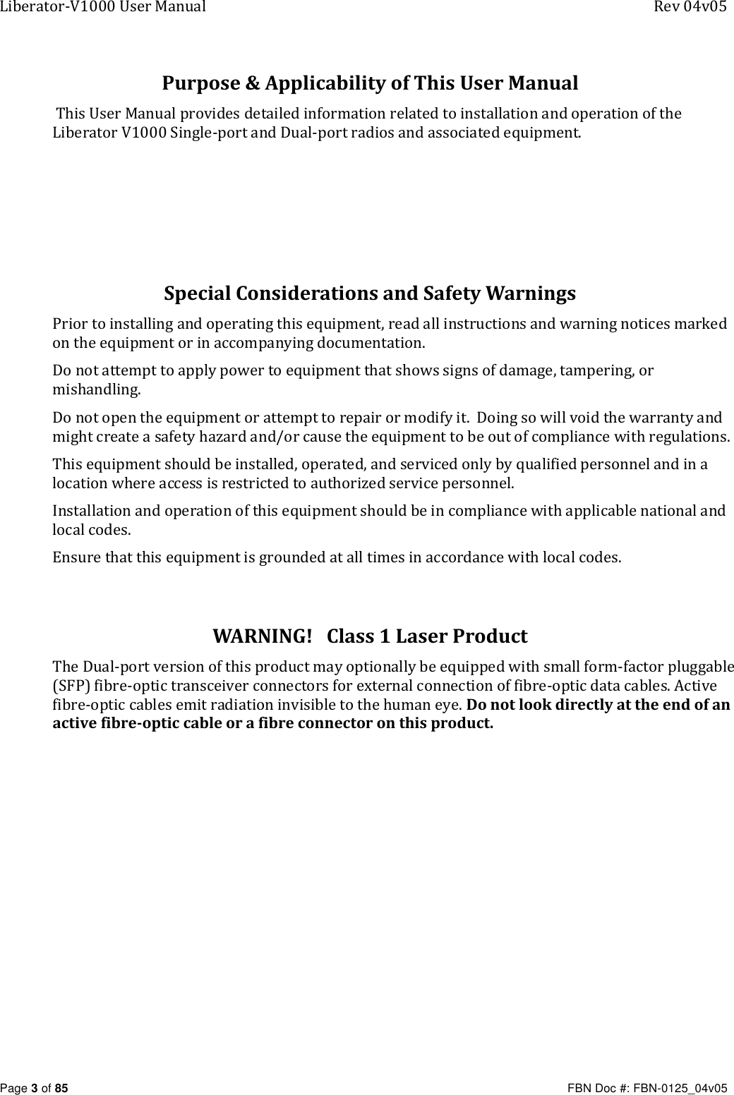
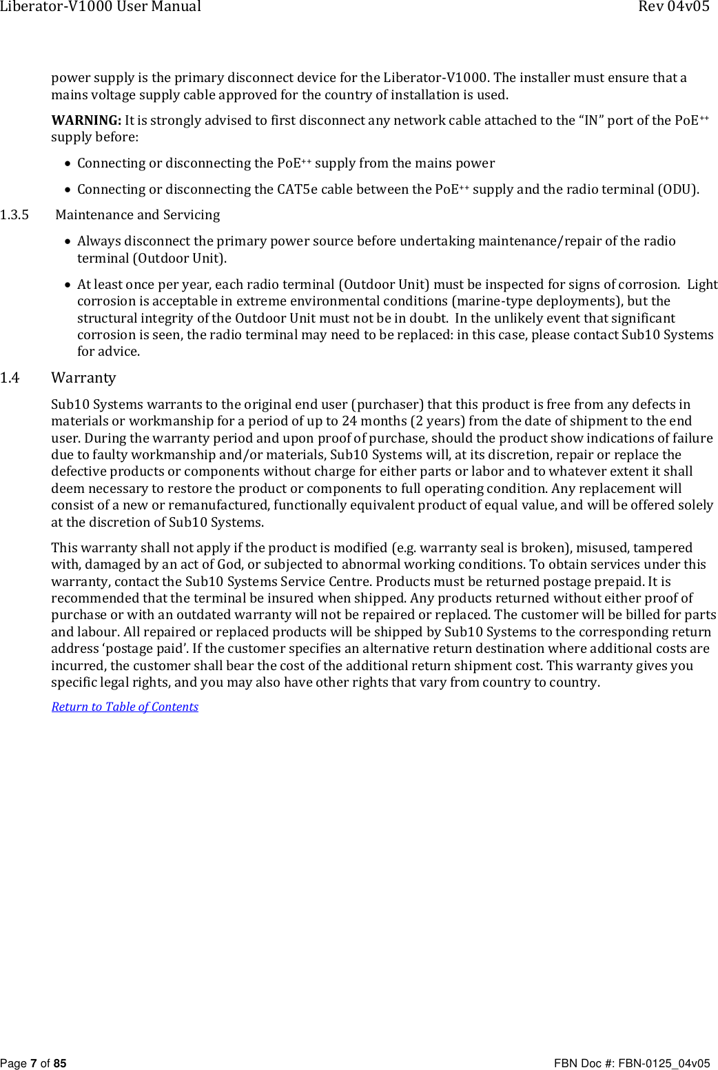
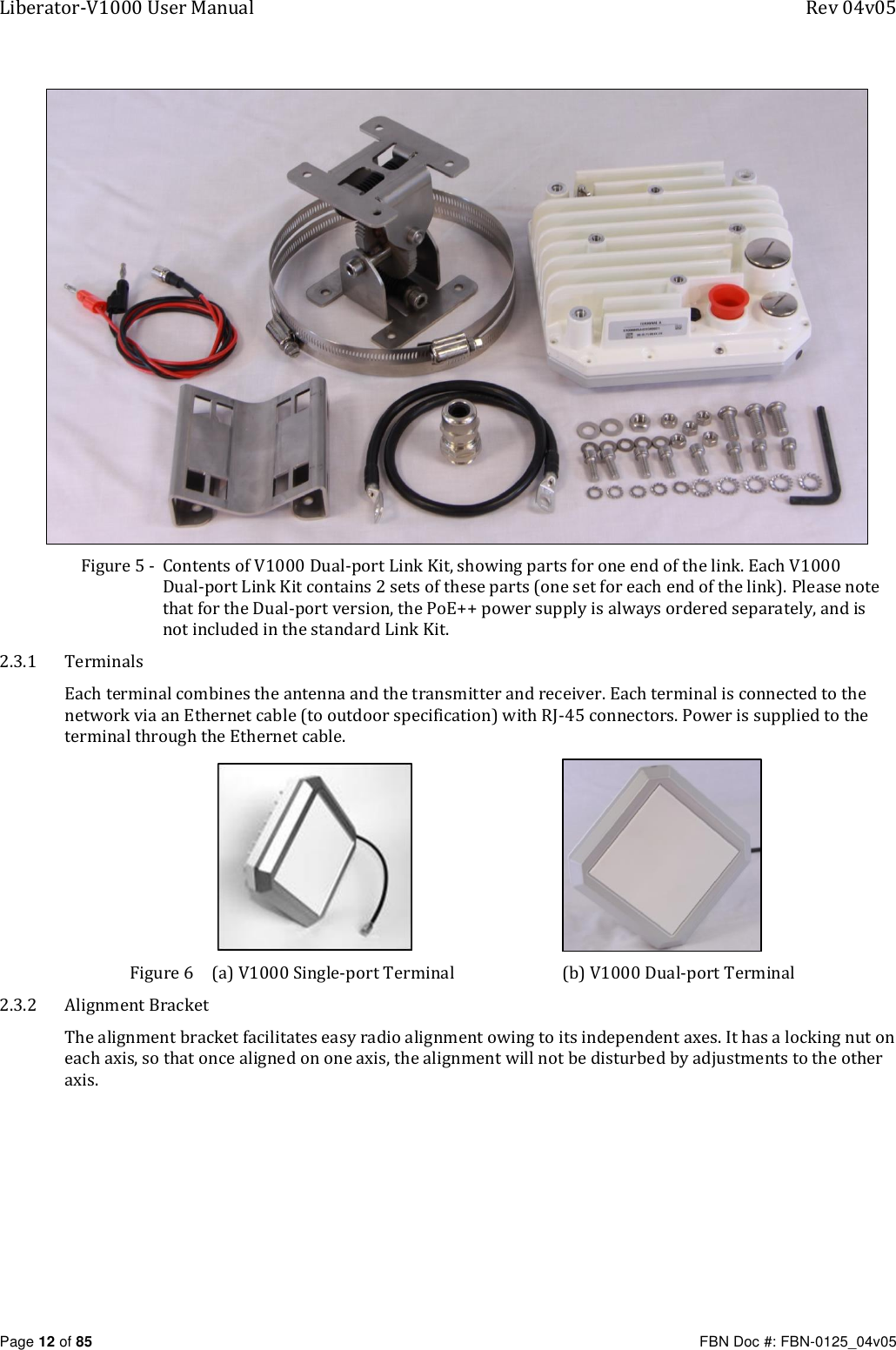
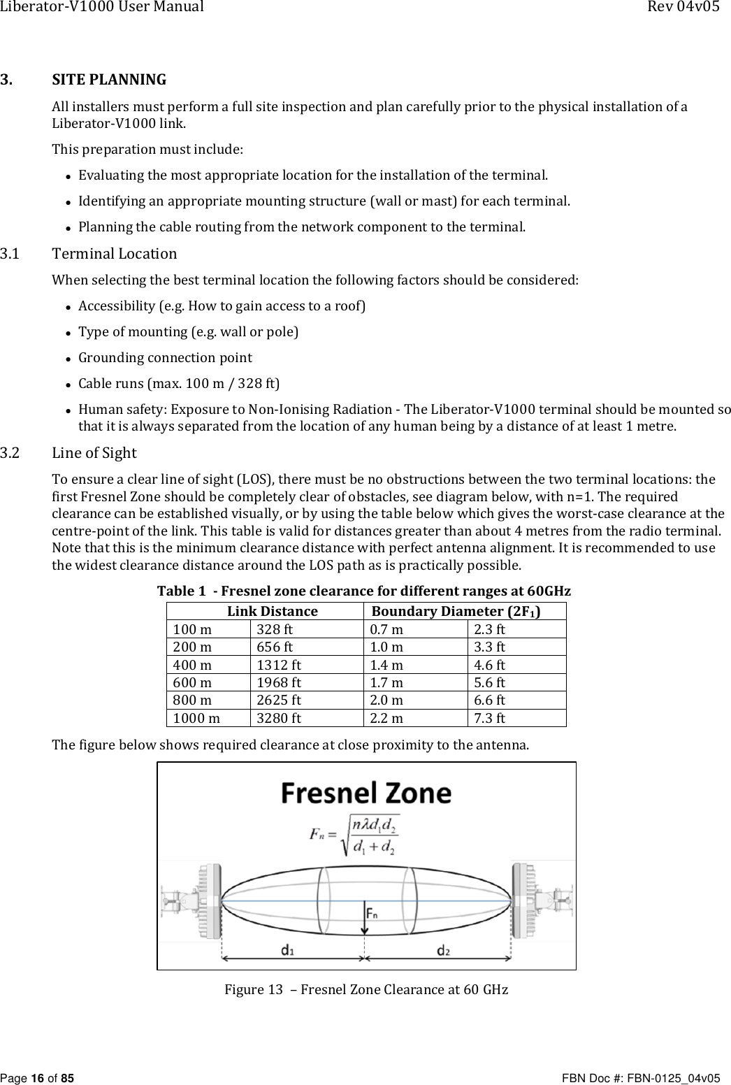
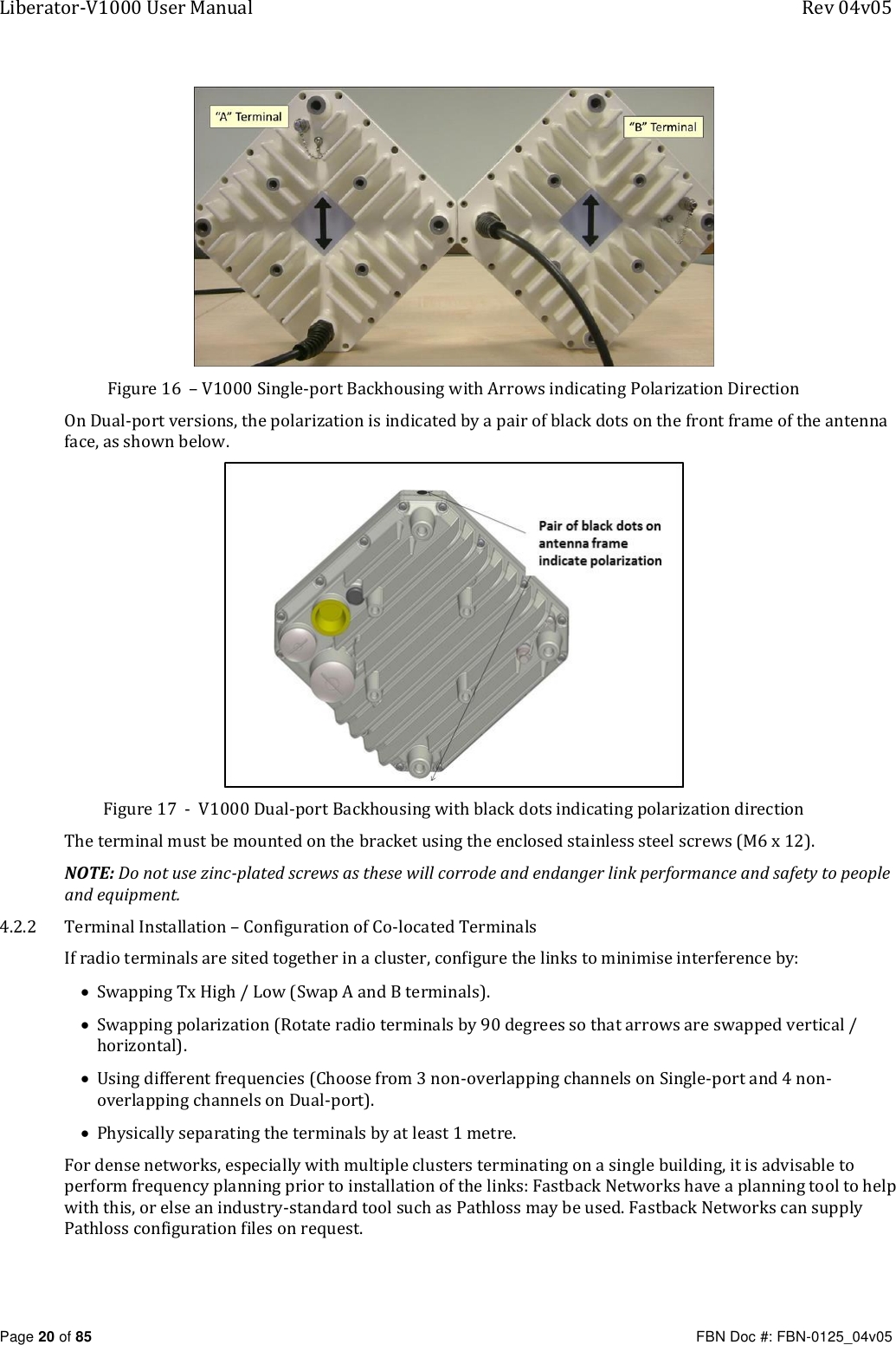
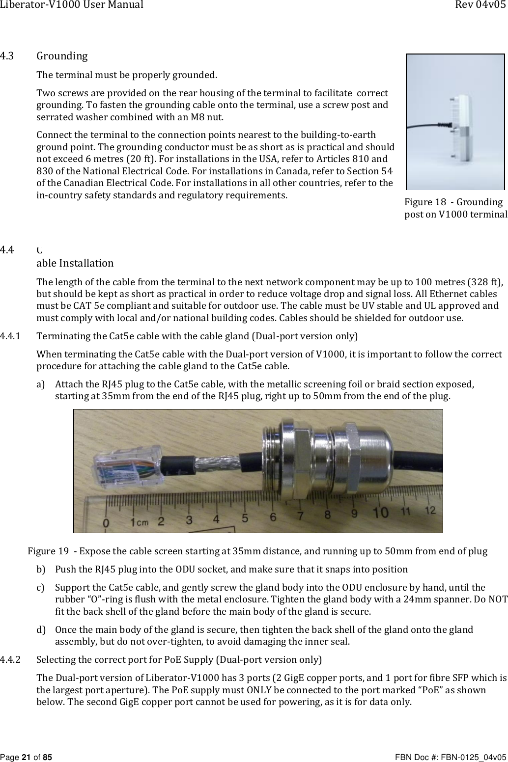
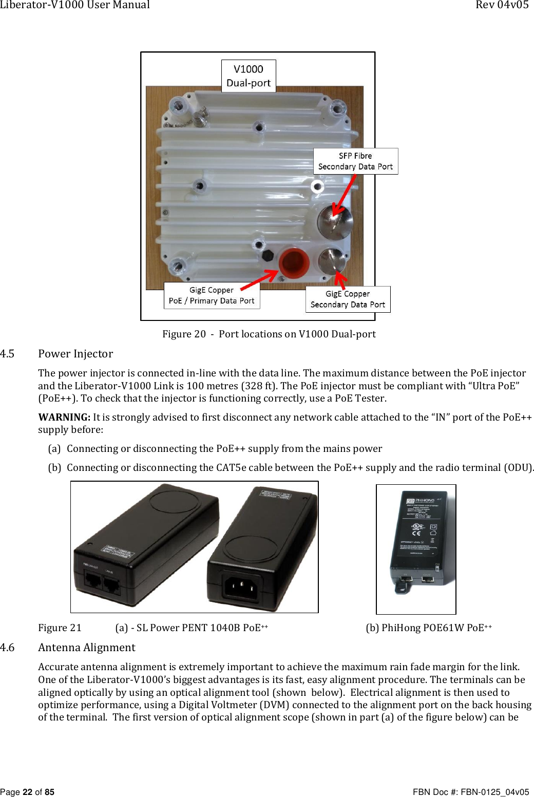
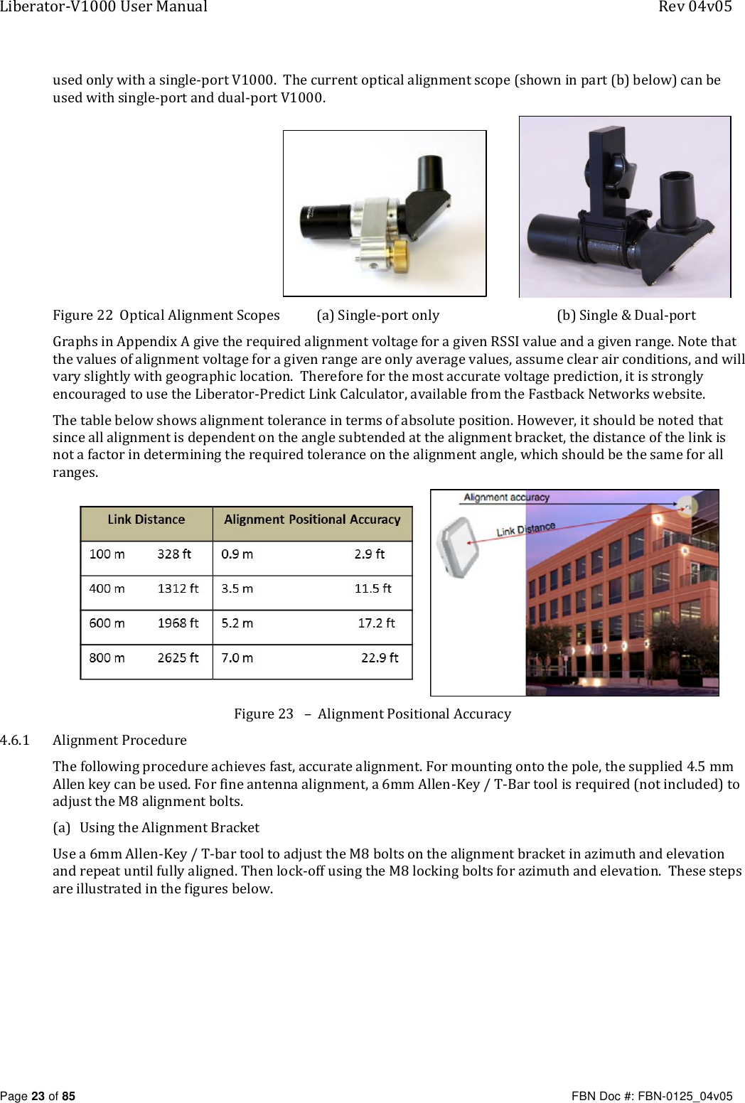
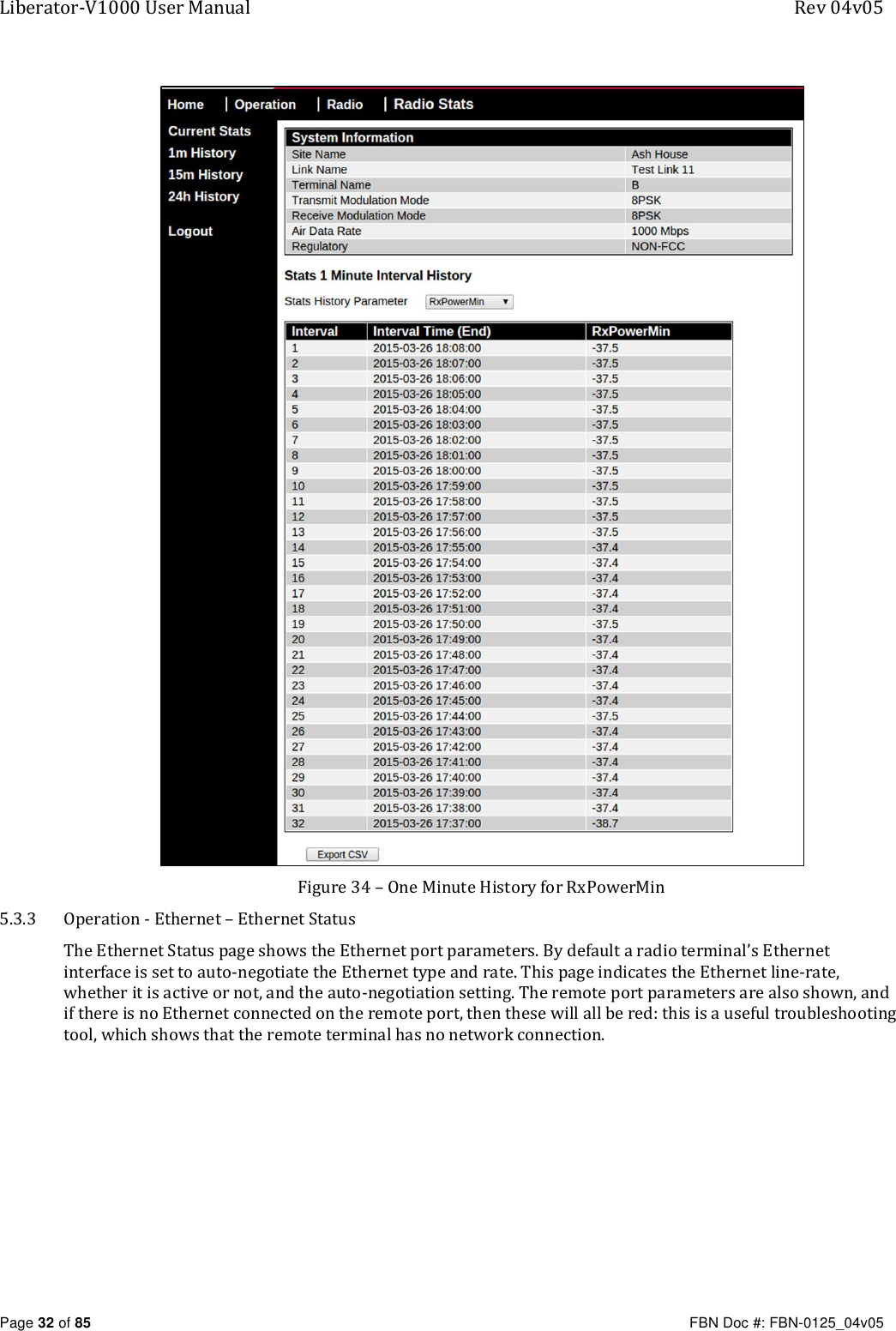
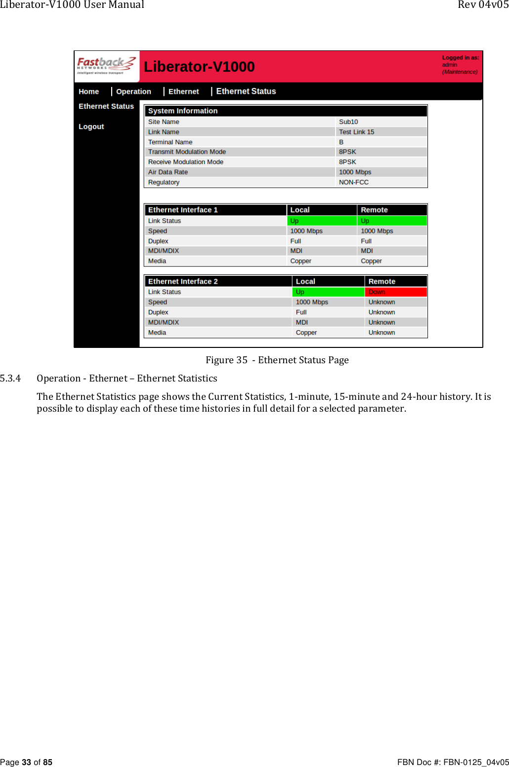
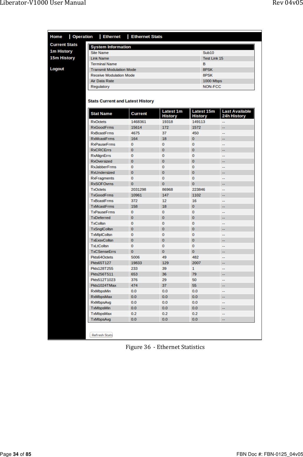
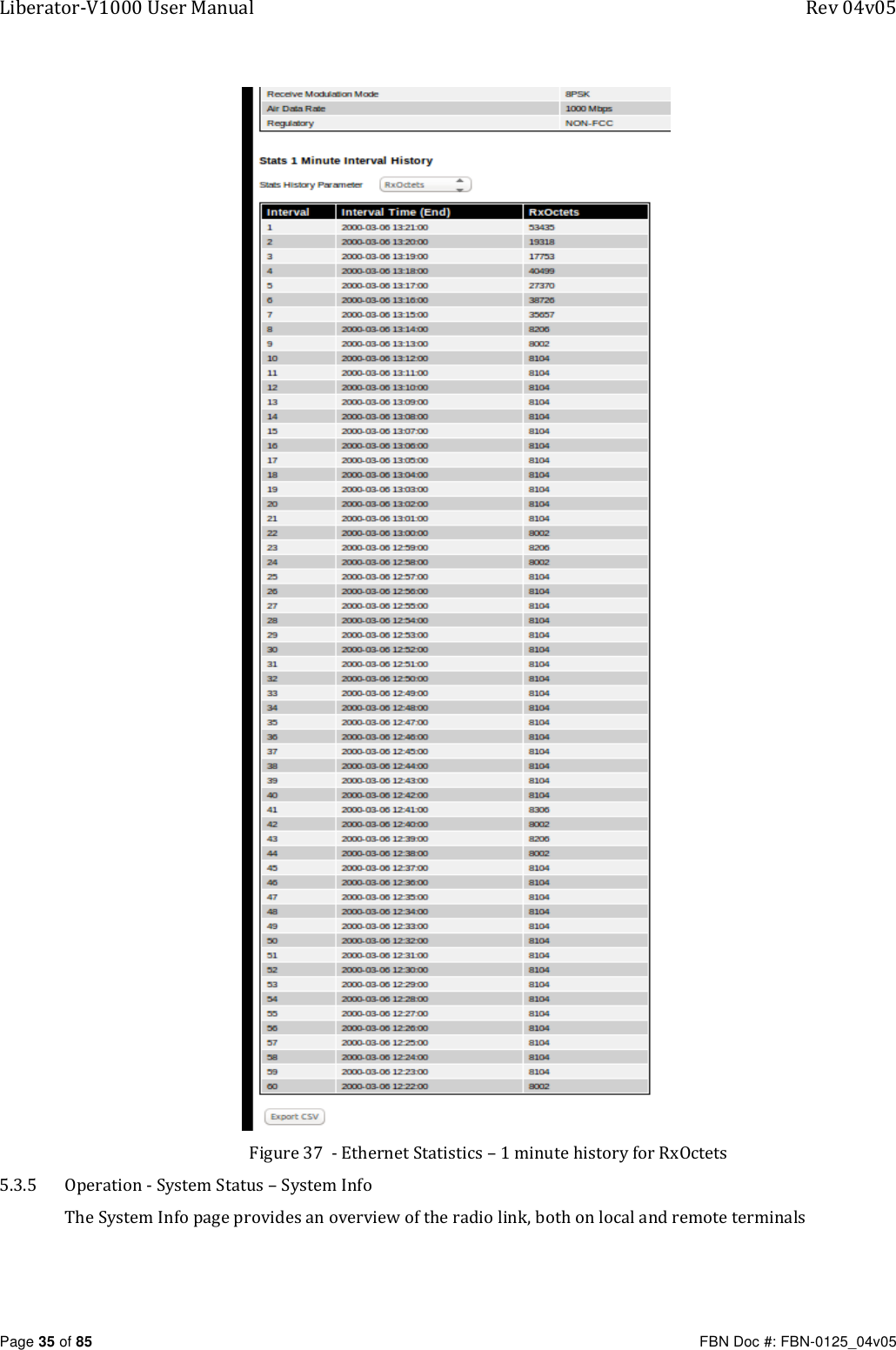
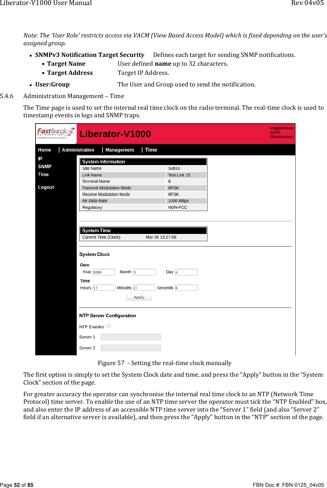
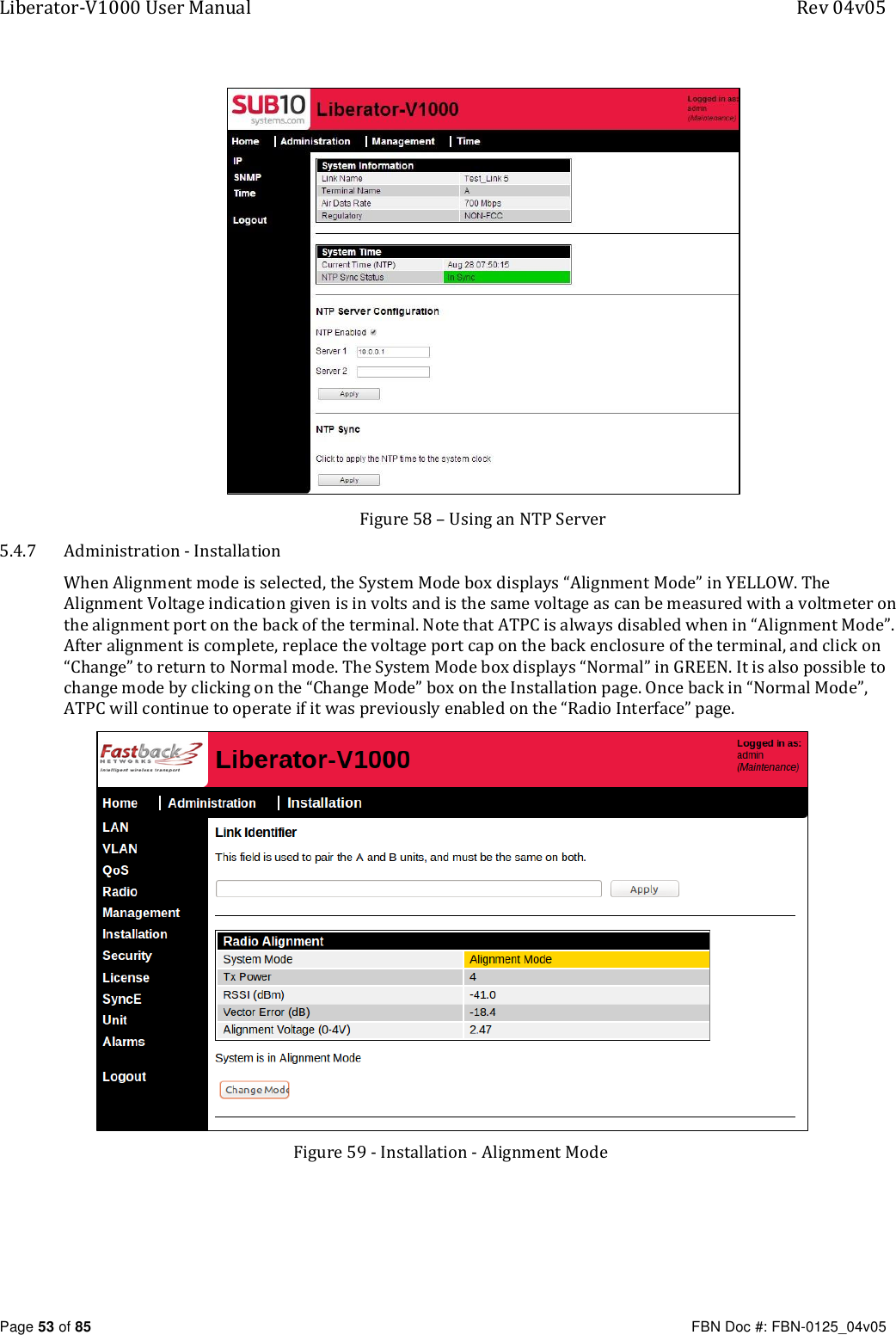
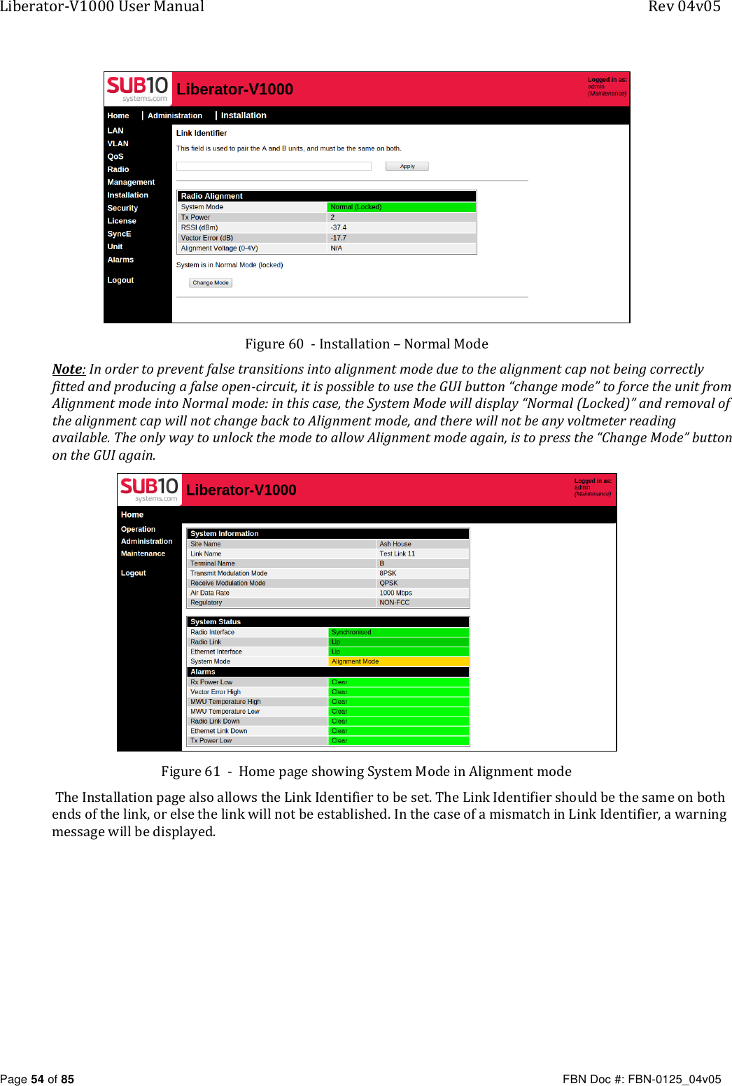
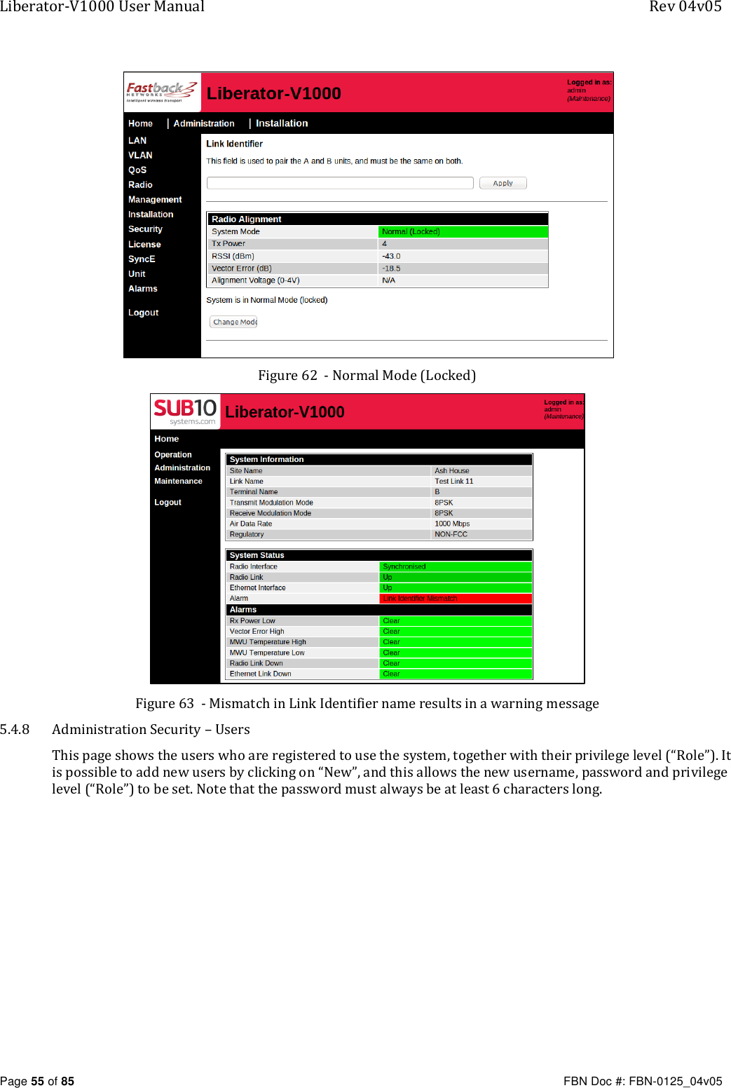
![Liberator-V1000 User Manual Appendix B – Regulatory Information Page 83 of 85 FBN Doc #: FBN-0125_04v05 1.2. Human Exposure to Non-Ionising Radiation in the USA There are regulations defining limits for exposure of the general public to non-ionising radiation which is produced by radio transmitters. This is called “RF Exposure”. (a) Reference Documents The documents applicable here are: [1] US Code of Federal Regulations, in particlar the policies, guidelines and requirements in Part 1 of Title 47 of the CFR. See (www.fcc.gov) [2] Guidelines and recommendations for evaluating compliance contained in FCC Bulletin 65 [3] Safety Code 6 on the Health Canada Website www.hc-sc.gc/ca/ (b) Recommended separation distance The radio terminal and antenna should always be mounted in such a way as to prevent human exposure to radio-frequencies, by ensuring that the following minimum safety distances are observed: Safety Distance = 1 metre on boresight. The antennas MUST be positioned to ensure that a minimum separation distance of 1 metre on antenna boresight is maintained between the installer or user and the antennas. The antennas MUST be positioned to ensure that no human being could be reasonably expected to come within 1 metre of the antenna during normal operation of the radio equipment.](https://usermanual.wiki/Skyline-Partners-Technology-Fastback-Networks/LIB-V1000E2/User-Guide-2952773-Page-83.png)