Skytech II 1003TX Remote Control Transmitter User Manual 1
Skytech II, Inc. Remote Control Transmitter 1
User Manual
SKYTECH 1001SR/P TH
REV. 09/02
Page 1 of 6
1001SR/P TH
INSTALLATION AND OPERATING INSTRUCTIONS
MULIT-FUNCTION WIRELESS REMOTE CONTROL SYSTEM
FOR OPERATING SERVO MOTORS VALVES OR PULSE SOLENOIDS VALVES
INTRODUCTION
This remote control system was developed to provide a safe, reliable, and user-friendly remote control system for gas heating appliances. The
system is operated manually from the transmitter. The system operates on radio frequencies (RF) within a 20' range using non-directional
signals. The system operates on one of 255 security codes that are programmed into the transmitter at the factory; the remote receiver's code
must be matched to that of the transmitter prior to initial use.
Review THERMO SAFETY SECTION under RECEIVER section. This high temperature safety feature shuts down
the appliance when a potentially unsafe condition exists.
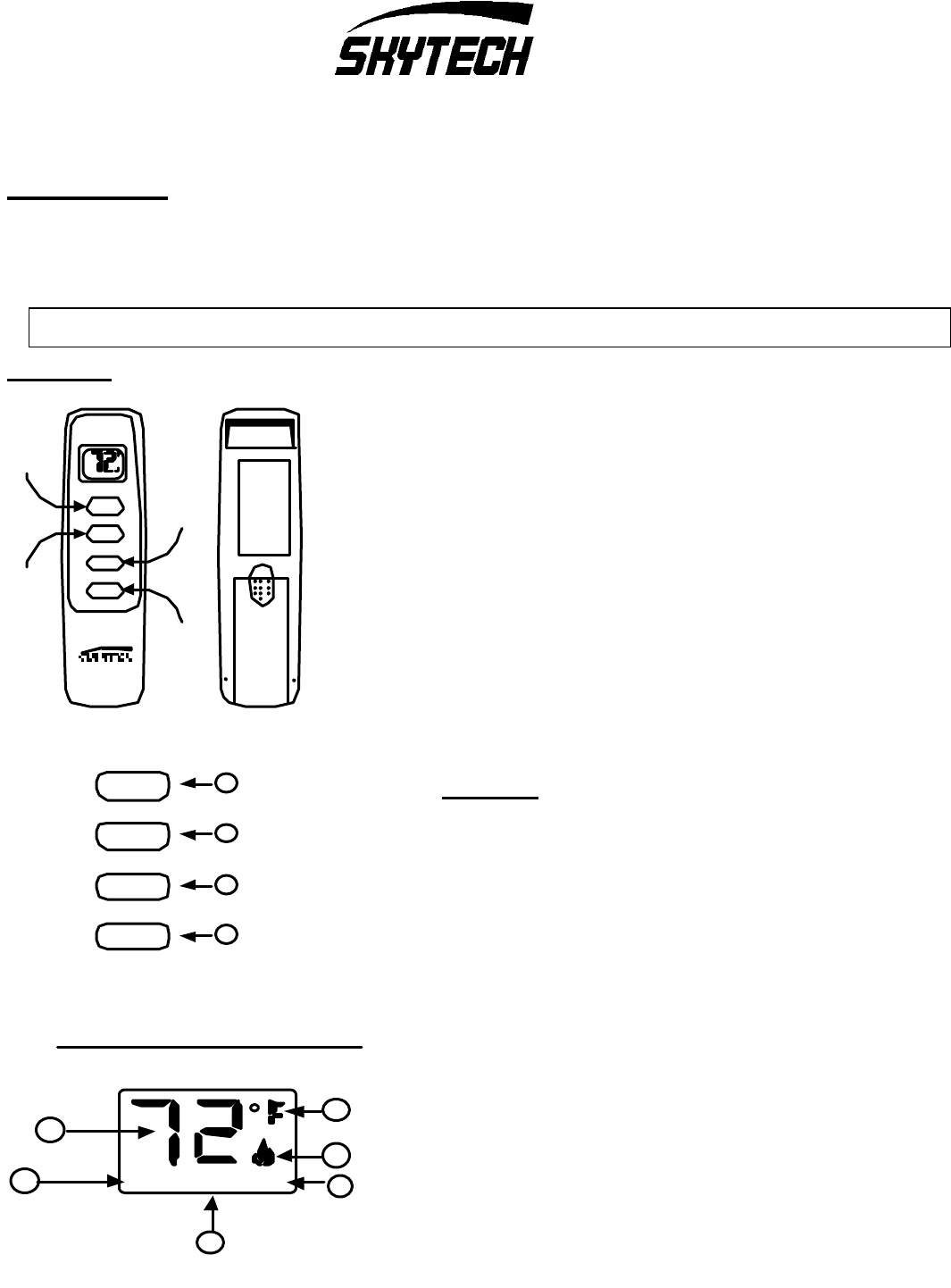
TRANSMITTER
This remote control SYSTEM offers the user a battery-operated remote control to power
up to a 6 VDC servo motor or solenoid such as those used with gas valves used in some
heater rated gas logs, gas fireplaces and other gas heating appliances.
The servo motor or solenoid circuit uses the battery power from the receiver to operate a
servo motor or solenoid. The circuit has reversing polarity software which reverses the
positive (+) and negative (-) output of the receiver's battery power to drive the servo
motor or solenoid forward/backward (HI/LO FLAME) or open/close (FLAME SOLENOID
- ON/OFF). The SYSTEM is controlled by the remote transmitter.
The transmitter operates on a (2) 1.5V AAA batteries made specifically for remote
controls and electronic lighters. Before using the transmitter, remove the insulation tab
protecting one end of the battery in the battery compartment.
It is recommended that ALKALINE batteries always be used for longer battery life and
maximum operational performance.
KEY SETINGS
• ON/HI -Operates unit to on position.
• LO/OFF - Operates unit to off position
• MODE - Changes unit from manual feature to thermo feature.
• SET - Sets temperature in thermo in feature.
1. DISPLAY Indicates CURRENT room temperature .
2. 0 F OR 0 C Indicates degrees Fahrenheit or Celsius.
3. FLAME Indicates burner/valve in operation.
4. ROOM Indicates remote is in THERMO operation.
5. TEMP Appears during manual operation.
6. SET Appears d uring time the of setting the desired temperature in
the thermo operation.
ON/HI
MODE
LO/OFF
BUTTON
WALL CLIP
SLOT
12V
BATTERY
COMPARTMENT
FRONT BACK
LO/OFF
SET
ON/HI
BUTTON
MODE
BUTTON
SET
BUTTON
ROOM
LCD - Liquid Crystal Display
TEMP
1
2
3
SET45
6
ON/HI
MODE
LO/OFF
SET
1
2
3
4
SKYTECH 1001SR/P TH
REV. 09/02
Page 2 of 6
SETTING 0 F / 0C SCALE
The factory setting for temperature is 0 F. To change this setting to
0 C, first
• Press the ON/HI key and the LO/OFF key on the transmitter at the same
time this will change from 0 F to 0 C. Follow this same procedure to
change from
0 C back to 0 F.
MANUAL FUNCTION
To operate the system in the manual mode do the following.
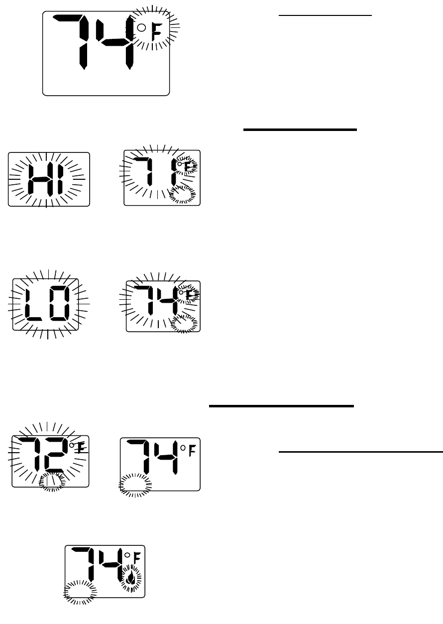
ON OPERATION
Press and hold the ON/HI key until the appliance flame comes on and reaches
the desired flame height or is at full on. During this time the LCD screen will
show HI, after 3 seconds the LCD screen will default to display room
temperature and the word TEMP will show.
OFF OPERATION
Press and hold the LO/OFF key until the appliance flame reaches the desire
flame height or completely shuts off. During this time the LCD screen will show
LO, after 3 seconds the LCD screen will default to display room temperature
and the word TEMP will show.
THERMOSTAT FUNCTION
SETTING DESIRED ROOM TEMPERATURE
This remote control system can be thermostatically controlled when the
transmitter is in the THERMO mode (SET must be displayed on the screen).
To set the DESIRED room temperature,
Press the MODE key the display will show the words SET TEMP and the
temperature display will began to flash.
Press and hold the SET key until the desired set temperature is reached then
release the SET key.
Press the MODE key to disengage the thermo mode. The word ROOM on the
LCD screen will not show when the thermo is not in operation.
NOTE: The highest SET temperature is 990 Fahrenheit (320 Celsius) and the
lowest temperature (450 F, or 60 C ).
TEMP
TEMPSET
THERMO SET
SCREEN DURING
ADJUSTING TO ON
SCREEN DURING
ADJUSTING TO OFF
TEMP
SCREEN AFTER 3
SECOUND DEFAULT
ROOM TEMP
THERMO OFF
ROOM TEMP
THERMO ON
TEMP
SCREEN AFTER 3
SECOUND DEFAULT
SKYTECH 1001SR/P TH
REV. 09/02
Page 3 of 6
OPERATIONAL NOTE: TO CONSERVE BATTERY POWER, CHANGES IN ROOM TEMPERATURE ARE ONLY UPDATED EVERY TWO
MINUTES.
The Thermo Feature on the transmitter operates the appliance whenever the ROOM TEMPERATURE varies a certain number of degrees from
the SET TEMPERATURE. This variation is called the “SWING” or TEMPERATURE DIFFERENTIAL. The normal operating cycle of an
appliance may be 2-4 times per hour depending on how well the room or home is insulated from the cold or drafts. The factory setting for the
“swing number” is 2. This represents a temperature variation of +/- 20 F (10 C between SET temperature and ROOM temperature, which
determines when the fireplace will be activated.
The transmitter has ON/HI and LO/OFF functions that are activated by pressing either button on the face of the transmitter. When a button on
the transmitter is pressed, a signal light on the transmitter illuminates to verify that a signal is being sent. Upon initial use, there may be a
delay of three seconds before the remote receiver will respond to the transmitter. This is part of the system's design. If the signal light does
not illuminate, check the position of the transmitter's battery.
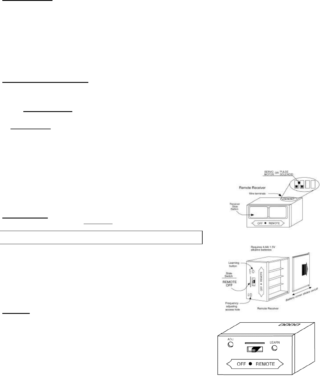
POWER SETTING - 1001SR or 1001P
The electronics in the remote control system have the capability of "powering" two different types of DC -powered components.
The RECEIVER comes from the factory programmed to provide continuous DC voltage (4.5 VDC to 6.0 VDC) to a servo motor and is referred
to as the SKYTECH 1001SR/P setting.
The RECEIVER can be reprogrammed, by the user, to provide "pulse" DC voltage ( 3.0 VDC) to a latching relay-solenoid and is referred to as
the SKYTECH 1001P setting.
Depending on the type of gas valve and/or solenoid controlling the gas flow in your fireplace system, the RECEIVER needs to be programmed
to the proper "power setting". To change the factory "power setting" from the 1001SR to the 1001P setting, first load the RECEIVER with a 4-
AA batteries as instructed in the REMOTE RECEIVER SECTION which follows. Then:
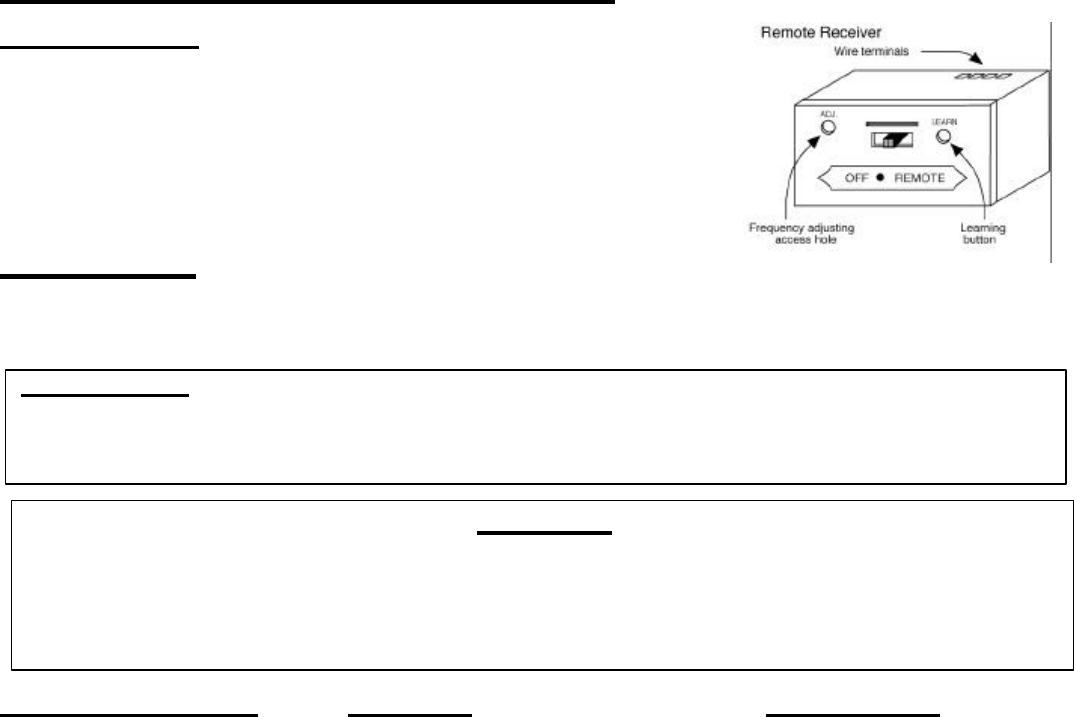
• Slide switch on RECEIVER to the remote position.
• Then push and hold in the LEARNING BUTTON on the front of the RECEIVER.
You will hear a continuous "beep sound" for about three seconds. Then, still holding in
the LEARN button, the "beep sound" will stop for about four seconds and then a second
"beep sound" of a different pitch, will be heard. The conversion from the 1001SR setting
to 1001P setting is complete. To reprogram RECEIVER to the 1001SR setting, repeat
process and receiver will reset to 1001SR setting.
• The LEARN button is used to set the unique security code for your remote control system.
The SECURITY CODE is reset during the "power setting" process.
REMOTE RECEIVER IMPORTANT
THE REMOTE RECEIVER SHOULD BE POSITIONED WHERE AMBIENT
TEMPERATURES DO NOT EXCEED 130° F.
The remote receiver (right) operates on four 1.5V AA-size batteries. It is recommended that
ALKALINE batteries be used for longer battery life and maximum microprocessor performance.
IMPORTANT: New or fully charged batteries are essential to proper operation of the remote
receiver as a servo motor's power consumption is substantially higher than standard remote
control systems.
NOTE: Th e remote receiver will only respond to the transmitter when the 2-position slide
button on the remote receiver is in the REMOTE position. The remote receiver houses the
microprocessor that responds to commands from the transmitter to control system operation.
FUNCTIONS:
• With the slide switch in the REMOTE position, the system will only
operate if the remote receiver receives commands from the transmitter.
Upon initial use or after an extended period of no use, the ON button
may have to be pressed for up to three seconds before activating servo
motor. If the system does not respond to the transmitter on initial use,
see Matching Security Codes.
• With the slide in the OFF position, the system is off.
• It is suggested that the slide switch be placed in the OFF position if you
will be away from your home for an extended period of time. Placing the
SKYTECH 1001SR/P TH
REV. 09/02
Page 4 of 6
slide switch in the OFF position also functions as a safety "lock out"
by both turning the system OFF and rendering the transmitter
inoperative.
INSTALLATION INSTRUCTIONS
WARNING
DO NOT CONNECT REMOTE RECEIVER DIRECTLY TO 110-120VAC POWER. THIS WILL BURN OUT THE
RECEIVER. FOLLOW INSTRUCTIONS FROM MANUFACTURER OF GAS VALVE FOR CORRECT WIRING
PROCEDURES. IMPROPER INSTALLATION OF ELECTRIC COMPONENTS CAN CAUSE DAMAGE TO
GAS VALVE AND REMOTE RECEIVER.
INSTALLATION
The remote receiver can be mounted on or near the fireplace hearth. PROTECTION FROM EXTREME HEAT IS VERY IMPORTANT. Like
any piece of electronic equipment, the remote receiver should be kept away from temperatures exceeding 130º F inside the receiver case.
Battery life is also significantly shortened if batteries are exposed to high temperatures.
Make sure the remote receiver switch is in the OFF position. It is recommended that 18 gauge stranded or solid wires (not included) are used
to make connections. For best results, use 18 gauge stranded or solid wire, with no splices and measuring no longer than 20 ft.
HEARTH MOUNT
The remote receiver can be placed on the fireplace hearth or under the fireplace, behind the control access
panel. Position where the ambient temperature inside the receiver case does not exceed 130º F.
NOTE: Black Button is used on Hearth Mount Applications.
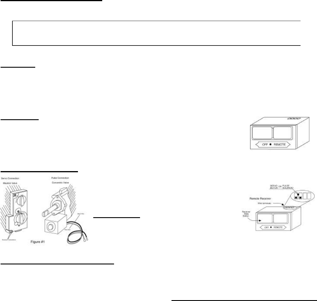
WIRING INSTRUCTIONS This remote receiver can be connected to either a manual valve
with a SERVO MOTOR or manual valves with a latching relay
that operates OFF/ON with a pulse signal. (See Figure #1).
Connect two 18 gauge stranded or solid wires from the remote
receiver (See figure to the right) terminals to the servo motor or
pulse solenoid.
IMPORTANT NOTE: Operation of these controls is dependent
on which wire is attached to which terminal. If operation of
control does not correspond to operating buttons on transmitter,
reverse wire installation at the receiver or at the control.
NOTE: Up to 6 VDC of power is provided at the receiver
terminal.
THERMO-SAFETY FEATURE - RECEIVER (T/S - RX)
When the ambient temperature at the THERMISTOR, inside the receiver case, reaches 130°F, the THERMISTOR will automatically send 10
seconds of power to the down or off terminal on the valve to shut the fireplace system down and the RECEIVER will begin emitting a series of
4 "beeps" every 2 seconds. When the ambient temperature, at the RECEIVER, drops between 120° F and 130° F, the user can reactivate the
fireplace by pushing either button on the transmitter. When any transmitter button is pressed, the THERMISTOR "resets" itself and the
fireplace will begin operating again. However, the "beeping" will continue, if the ambient temperature remains between 120° F and 130° F.
This "beeping" alerts the user that the RECEIVER should be repositioned so the ambient temperature drops below 120° F.
When the temperature drops below 120° F, the "beeping" will cease, providing the user has "reset" the THERMISTOR by pushing either
transmitter button to operate the fireplace. Allow sufficient time for receiver to cool below 120° F, and then press transmitter button to stop
beeping.
SKYTECH 1001SR/P TH
REV. 09/02
Page 5 of 6
GENERAL INFORMATION
MATCHING SECURITY CODES
Each transmitter can use one of 255 unique security codes. It may be necessary to program the remote receiver to LEARN the security code
of the transmitter upon initial use, if batteries are replaced, or if a replacement transmitter is purchased from your dealer or the factory. When
matching security codes, be sure slide button on the receiver is in the REMOTE position; the code will NOT "LEARN" if the slide switch is in
the OFF position. Program the remote receiver to LEARN a new security code by pushing in the LEARN button on the top of the remote
receiver and then pressing any button on the transmitter. A change in the beeping pattern, at the receiver, indicates the transmitter's code has
been programmed into the receiver. When an existing receiver is matched to a new transmitter, the new security code will overwrite the old
one.
The microprocessor that controls the security code matching procedure is controlled by a timing function. If you are unsuccessful in matching
the security code on the first attempt, wait 1 - 2 minutes before trying again--this delay allows the microprocessor to reset its timer circuitry--
and try up to two or three more times.
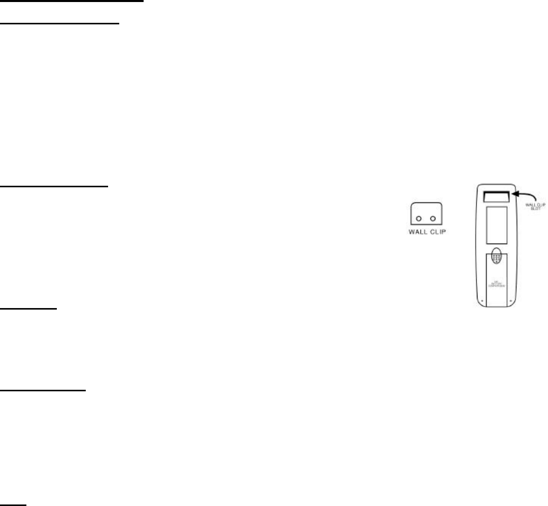
TRANSMITTER WALL CLIP
The transmitter can be hung on a wall using the clip provided. If the clip is installed on a solid wood
wall, drill 1/8" pilot holes and install with the screws provided. If it is installed on a plaster/wallboard
wall, first drill two 1/4" holes into the wall. Then use a hammer to tap in the two plastic wall anchors
flush with the wall; then install the screws provided.
BATTERY LIFE
Life expectancy of the alkaline batteries in the 1001SR can be up to 12 months depending on use of the servo function. Check all batteries
annually. When the transmitter no longer operates the remote receiver from a distance it did previously (i.e., the transmitter's range has
decreased) or the remote receiver does not function at all, the batteries should be checked. It is important that the remote receiver batteries
are fully charged, providing combined output voltage of at least 4.5volts. The transmitter should operate with as little as 2.5 volts
battery power.
NOTE: Extensive use of the SERVO MOTOR setting will reduce the receiver's battery life significantly.
TROUBLE SHOOTING
If you encounter problems with your fireplace system, the problem may be with the fireplace itself or it could be with the 1001SR remote
system. Review the fireplace manufacturer's operation manual to make sure all connections are properly made. Then check the operation of
the remote in the following manner:
• Make sure the batteries are correctly installed in the RECEIVER. One reversed battery will keep receiver from operating properly.
• Check battery in TRANSMITTER to make sure contacts are touching (+) and (-) ends of battery. Bend metal contacts in for tighter fit.
• Be sure RECEIVER and TRANSMITTER are within 20'-25' operating range.
• Keep RECEIVER from temperatures exceeding 13 0° F. Battery life shortened when ambient temperatures are above 115° F.
• If RECEIVER is installed in tightly enclosed metal surround, the operating distance will be shortened.
NOTE: A receiver located in an area, where the ambient temperature inside the case exceeds 130° F, will cause the THERMO-
SAFETY feature to cut in, requiring you to reposition the receiver to stop the warning beeps, and to "reset" the receiver's
operation.
• Due to handling and shipping of the unit, handling or dropping of the transmitter by the customer, and/or heat conditions at the receiver,
some receivers may need an occasional frequency adjustment. This adjustment is made to improve the communication and operating
distance between the transmitter and the receiver. Follow the steps below for making the adjustment.
SKYTECH 1001SR/P TH
REV. 09/02
Page 6 of 6
FREQUENCY (DISTANCE) ADJUSTMENT PROCEDURE
RECEIVER ADJUSTMENT
1. To adjust at the receiver, use a small slotted screwdriver. Turn the adjustment (ADJ)
screw counter-clockwise about 5° or maximum of 1/8 turn. This should correct the
distance problem.
2. If that does not correct the problem, return adjustment screw to original position and then
turn adjustment screw clockwise.
This adjustment is like tuning your radio. If you keep turning the adjustment screw, in either
direction, you will go past the proper setting (tuning).
SPECIFICATIONS
BATTERIES: Transmitter (2) 1.5 volt AAA t bateries
Remote Receiver 6V - 4 ea. AA 1.5 Alkaline FCC ID No.'s: transmitter - K9L1003TX; receiver - K9L300IRX
Operating Frequency: 318.79 MHZ Canadian ISC ID No.'s: transmitter – (XXXXX); receiver - 2439 102 728A
FOR TECHNICAL SERVICE, CALL: U. S. INQUIRIES CANADIAN INQUIRIES
888/672-8929 or 877/472-3923
260/459-1703
WEBSITE: skytechsystem.com
MANUFACTURED EXCLUSIVELY FOR SKYTECH II, INC.
FCC REQUIREMENTS
NOTE: THE MANUFACTURER IS NOT RESPONSIBLE FOR ANY RADIO OR TV INTERFERENCE CAUSED BY
UNAUTHORIZED MODIFICATIONS TO THIS EQUIPMENT. SUCH MODIFICATIONS COULD VOID THE USER’S
AUTHORITY TO OPERATE THE EQUIPMENT.
WARRANTY
All warranty information is listed on the warranty sheet packed with this product. If you did not
receive this warranty sheet, please contact Skytech Systems, Inc. at the following:
9230 Conservation Way, Fort Wayne, IN 46809
(888) 672-8929 or (260) 459-1703

Federal Communication Commission Interference Statement
This equipment has been tested and found to comply with the limits for a Class B digital device, pursuant
to Part 15 of the FCC Rules. These limits are designed to provide reasonable protection against harmful
interference in a residential installation. This equipment generates, uses and can radiate radio frequency
energy and, if not installed and used in accordance with the instructions, may cause harmful interference
to radio communications. However, there is no guarantee that interference will not occur in a particular
installation. If this equipment does cause harmful interference to radio or television reception, which can
be determined by turning the equipment off and on, the user is encouraged to try to correct the
interference by one of the following measures:
• Reorient or relocate the receiving antenna.
• Increase the separation between the equipment and receiver.
• Connect the equipment into an outlet on a circuit different from that to which the receiver is
connected.
• Consult the dealer or an experienced radio/TV technician for help.
This device complies with Part 15 of the FCC Rules. Operation is subject to the following two
conditions: (1) This device may not cause harmful interference, and (2) this device must accept
any interference received, including interference that may cause undesired operation.
Caution:. Any changes or modifications not expressly approved by the party responsible for compliance
could void the user's authority to operate this equipment.