Skytech II 3301TX Remote Control Transmitter User Manual 2
Skytech II, Inc. Remote Control Transmitter 2
Updated user manual
Skytech 3001
REV 12/01
Page 1 of 8
3301
INSTALLATION AND OPERATING INSTRUCTIONS
INTRODUCTION
This SKYTECH remote control system was developed to provide a safe, reliable, and user-friendly remote control system for gas heating
appliances. The system can be operated thermostatically or manually from the transmitter. The system operates on radio frequencies (RF)
within a 20'’range using non-directional signals. The system operates one of 1,048,576 security codes that are programmed into the
transmitter at the factory; the remote receiver’s code must be matched to that of the transmitter prior to initial use.
The transmitter operates on 2 AAA -size 1.5V batteries. It is recommended that ALKALINE
batteries always be used for longer battery life and maximum operational performance.
IMPORTANT: New or fully charged batteries are essential for proper operation of the multi-
function transmitter. Insert 2 AAA-size 1.5 V batteries into the battery compartment on the back
of the transmitter, positioning the (+) and (-) ends of the batteries as indicated on the casing.
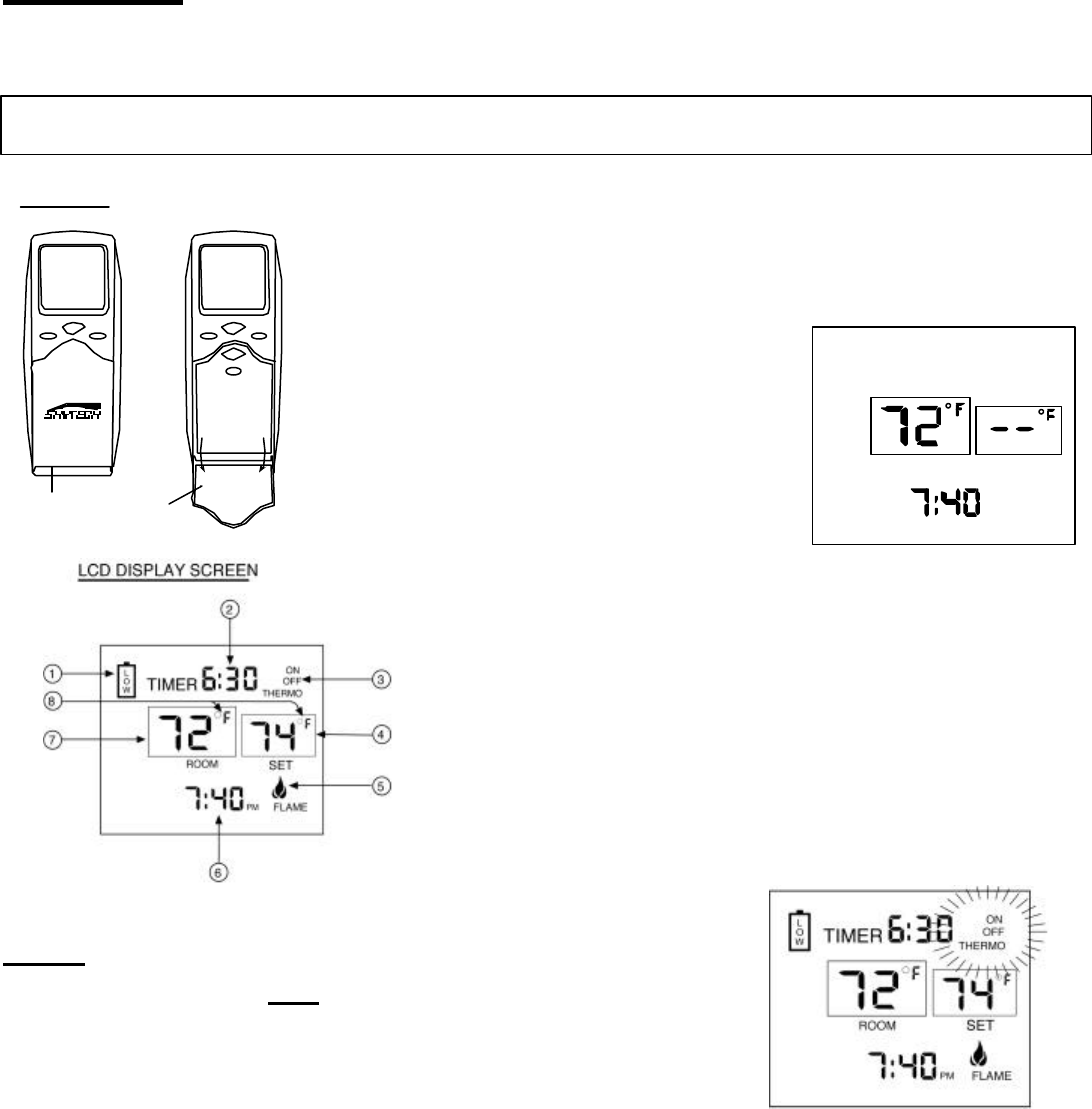
When the batteries are inserted, the screen at right (with
similar numbers) will display.
Note: If a LOW battery icon appears on the screen,
check the position of the batteries; a reversed battery
will activate the LOW battery icon.
Note: Due to the sensitive temperature-monitoring
components in the transmitter, it may be necessary to
allow the transmitter to stabilize to room temperature
before accurate room temperatures are displayed on
the screen. If the transmitter is activated from a
severe cold condition, it can take up to fifteen minutes
for accurate temperature readings to appear.
1. LOW- Battery power is low. Replace batteries within two weeks.
2. TIMER- Indicates time remaining before system shuts off, when timer-programmed;
9-hour maximum setting.
3. MODE- Indicates operation MODE of system. ON indicates the system is on, either
manually or thermostatically. OFF indicates the entire system is turned
off..THERMO indicates the system will automatically cycle on/off, depending
on programmed
4. SET- Indicates desire SET room temperature for THERMO operation
5. FLAME – Indicates burner/valve in operation.
6. CLOCK – Indicates the current time in AM/PM
7. ROOM – Indicates CURRENT room temperature.
8. 0 F indicates degrees Fahrenheit ( 0C
indicates degrees Celsius).
FUNCTIONS
To operate the system, press the MODE button on the front of the transmitter to select the
operational MODE desired.
• ON indicates the system is on, either manually, timed or thermostatically.
• THERMO indicates the system will automatically cycle ON/OFF, depending
• on programmed set temperature.
• OFF indicates the entire system is turned off.
Review
COMMUNICATION SAFETY SECTION under TRANSMITTER
section and THERMO SAFETY SECTION under REMOTE
RECEIVER
section. These signal/temperature safety features shut down the fireplace system when a potentially unsafe condition exists.
TRANSMITTER
Cover Closed
UPDOWN
MODE
UPDOWN
MODE
TIMER
TIME
SET
Cover
Open
ROOM
OFF
SET
PM
LCD DISPLAY
Skytech 3001
REV 12/01
Page 2 of 8
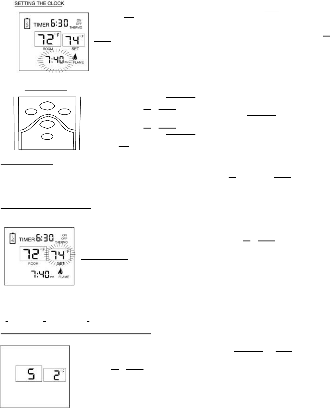
Flip down the plastic cover on the front of the transmitter to expose the “SET” buttons. The flip cover
protects the SET buttons from being changed accidentally. Close the cover after completing the
following settings/programming.
Flashing numbers on the display indicate the system is awaiting user input, such as using the UP and
DOWN buttons to program a new setting. If no change is made to flashing digits within 15 seconds,
the system will complete the procedure last programmed and reset the display to its normal state.
1. Press and hold the TIMER/TIME button on the transmitter for more than two seconds. The
hour digit(s) will begin flashing.
2. Press the UP or DOWN button until the desired hour is displayed in AM or PM.
3. After setting the desired hour, press and release the TIMER/TIME button again to set the
minutes; the minute digits will begin flashing.
4. Press the UP or DOWN button until the desired minutes are displayed.
5. Press and hold the TIMER/TIME button again for more than two seconds. The time digits
will cease flashing, indicating the clock has been successfully set. You may also press the
SET button on the transmitter to stop the time digits from flashing and set the time.
SETTING 0 F / 0C SCALE
The factory setting for temperature is 0 F. To change this setting to 0 C, first press and hold the UP button and the DOWN button on the
transmitter at the same time. Follow this same procedure to change from 0 C back to 0 F. When changing between the 0 F and 0C scales, the
temperature in the SET frame defaults to the lowest temperature (450 F, or 60 C
). The highest SET temperature is 990 Fahrenheit (32 0
Celsius).
SETTING DESIRED ROOM TEMPERATURE
This remote control system can be thermostatically controlled when the transmitter is in the THERMO mode
(THERMO must be displayed on the screen). To set the DESI RED room temperature, press the MODE
button to place the transmitter into THERMO mode, then press the UP or DOWN button to select the desired
room temperature. The highest SET temperature is 990 Fahrenheit (320 Celsius).
OPERATIONAL NOTE: TO CONSERVE BATTERY POWER, CHANGES IN ROOM TEMPERATURE ARE
AUTOMATICALLY UPDATED EVERY TWO MINUTES TO THE TRANSMITTER.
The Thermo Mode on the transmitter operates the appliance whenever the ROOM TEMPERATURE varies a
certain number of degrees from the SET TEMPERATURE. This variation is called the “SWING” or
TEMPERATURE DIFFERENTIAL. The normal operating cycle of an appliance may be 2 -4 times per hour
depending on how well the room or home is insulated from the cold or drafts. A smaller “swing number” increases the number of cycles so the
room temperature is more constant. A larger “swing number” decreases the number of cycles, which saves energy, in most cases. The
factory setting for the “swing number” is 2. This represents a temperature variation of +/- 20 F (10 C) between SET temperature and ROOM
temperature, which determines when the fireplace will be activated. The “SWING” number values are:
1=+ 10 F (.50 C), 2= + 20 F (10 C) and 3 = + 3 0 F (1.60 C).
SETTING THE TEMPERATURE SWING (TEMPERATURE DIFFERENTIAL)
1. To change the temperature “SWING” setting (1-3), press the TIMER/TIME and DOWN buttons
simultaneously to display the current “SWING” setting in the SET TEMP frame. The letter “S” will
display in the ROOM TEMP frame on the LCD screen.
2. Press the UP or DOWN button to change the temperature differential or “SWING” (1-3). See above for 1-3
“SWING” temperature valves.
BUTTON SETTINGS
UPDOWN
MODE
TIMER
TIME
SET
Skytech 3001
REV 12/01
Page 3 of 8
3. To store the “swing number press the SET button or allow 15 seconds to lapse, and the new “swing number’ will be automatically
programmed.
MANUAL CHECK OF “ SWING” OR TEMPERATURE DIFFERENTIAL
The operation of the factory set “THERMO SWING” can be checked by adjusting the SET TEMP 20 F above or below the room temperature.
This will cause the system to turn ON or OFF. Normally the system will only respond to temperature changes every two minutes. Manually
changing the SET temperature will activate the system in less than 10 seconds. IF the “SWING” is changed, then a new room temperature
0 F.
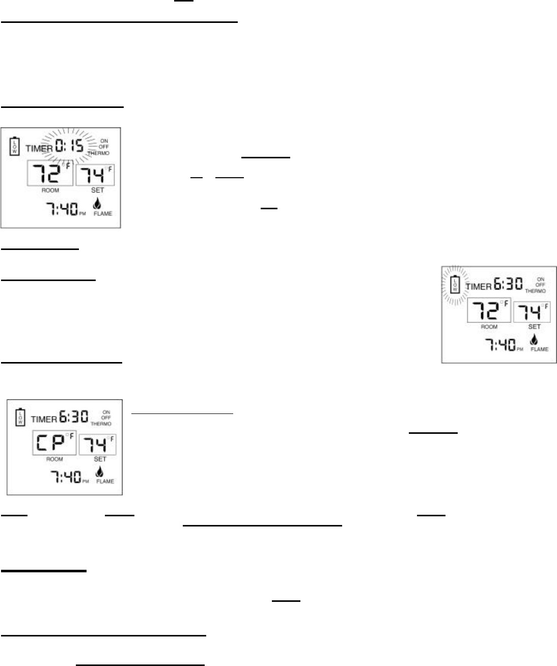
SETTING THE COUNTDOWN TIMER
This remote control system can operate with a built-in countdown timer when the transmitter is in the ON or
THERMO modes (THERMO or ON must be displayed on the screen).
1. Press and release the TIME R/TIME button on the transmitter. The word TIMER and 0:15 flash on the
screen.
2. Press the UP or DOWN button on the transmitter to begin advancing through each of the countdown
time options. Available countdown times are 15 minutes, 30 minutes, 45 minutes, 1 hour, 1 hour 30
minutes, 2 hours, 2 hours 30 minutes, and each additional half-hour up to nine hours.
3. To set the TIMER press the SET button on the transmitter if the system is ON. It will remain on until the
time has expired. If the system is in the THERMO mode, it will cycle on and off as the room
temperature requires until the “time” has expired.
OPERATIONAL NOTE: When the timer is used in the THERMO mode, the THERMO operation will discontinue when the “time” has expired.
LOW/BATTERY INDICATOR
The word LOW outlined by a battery on the left side of the LCD screen will appear when battery power has
dropped significantly. At this time, approximately two weeks of battery power remains until the transmitter
may experience partial or complete loss of functions. NOTE: A reversed battery will activate the LOW
battery icon.
CHILDPROOF “LOCK-OUT” – (CP)
This SKYTECH remote control includes a CHILDPROOF “LOCK-OUT” feature that allows the user to “LOCK-OUT” operation of the appliance,
from the TRANSMITTER.
SETTING “LOCK-OUT” –(CP)
1. To activate the “LOCK-OUT” feature, press and hold the UP and TIMER/TIME buttons, together, for 5
seconds. The letters CP will appear in the TEMP frame on the LCD screen.
• To disengage the “LOCK-OUT”, press and hold the UP and TIMER buttons, together for 5 seconds or
more, and the letters CP will disappear from the LCD screen and the transmitter will return to its
normal operating condition.
NOTE: If the appliance is already operating in the ON or THERMO MODES, engaging the “LOCK-OUT” will not cancel the operating MODE.
Engaging the “LOCK-OUT” prevents only the manual operation of the TRANSMITTER. If in the auto modes, the THERMO operation will
continue to operate normally. To totally “LOCK-peration of the TRANSMITTER’S operating signals; the transmitter’s MODE must
be set to OFF.
TRANSMITTER
The SKYTECH remote control operates, on RF (radio frequency) signals that are sent by the TRANSMITTER (remote) to the RECEIVER that
operates the appliance. It is recommended that the TRANSMITTER always be located within the 20 foot operating range, preferably in the
same room in which the appliance is located.
THERMO UPDATING FEATURE –TRANSMITTER – (T/S –TX)
This SKYTECH remote control has a THERMO UPDATING Feature built into its software. The THERMO UPDATING Feature operates in the
following manner, but only in the THERMO MODES:
Skytech 3001
REV 12/01
Page 4 of 8
The transmitter normally reads the ROOM temperature every 2 minutes checking the ROOM temperature against the SET
temperature and then sends a signal to the receiver.
COMMUNICATION – SAFETY – TRANSMITTER – (C/S – TX)
This SKYTECH remote control has a COMMUNICATION –SAFETY function built into its software. It provides an extra margin of safety when
the TRANSMITTER is out of the normal 20 foot operating range of the receiver.
The COMMUNICATION – SAFETY feature operates in the following manner, in all OPERATING MODES – ON/ ON THERMO/ ON TIMER.
At all times and in all OPERATING MODES, the transmitter sends an RF signal every 60 minutes, to the receiver, indicating
that the transmitter is within the normal operating range of 20 feet. Should the receiver NOT receive a transmitter signal every 60
minutes, the IC software, in the RECEIVER, will begin a 2-HOUR (120-minute) countdown timing function. If during this 2-hour period,
the receiver does not receive a signal from the transmitter, the receiver will shut down the appliance being controlled by the receiver.
The RECEIVER will then emit a series of rapid “beeps” for a period of 10 seconds. Then after 10 seconds of rapid beeping, the
RECEIVER will continue to emit a single “beep” every 4 seconds until a transmitter MODE
Button is pressed to reset the receiver. The intermittent 4 second beeping will go on for as
long as the receiver’sbatteries last which could be in excess of one year.
To “reset” the RECEIVER and operate the appliance, you must press the MODE button on the
transmitter. The word ON must display on the LCD screen. By turning the system to ON, the
COMMUNICATION -SAFETY operation is overridden and the system will return to normal
operation depending on the MODE selected at the transmitter. The COMMUNICATION –
SAFETY feature will reactivate should the transmitter be taken out of the normal operating
range or should the transmitter’s batteries fail or be removed.
REMOTE RECEIVER
The remote receiver operates on 4 AA-size 1.5V batteries. It is recommended that ALKALINE batteries be used for longer battery life and
maximum microprocessor performance. IMPORTANT: New or fully charged batteries are essential for proper operation of the remote receiver.
The remote receiver houses the microprocessor that responds to commands from the transmitter to control system operation. It emits one
beep when it receives an ON or OFF command manually, but no beep when cycling on and off automatically in THERMO mode. The remote
receiver has a 3-position slide switch for selecting the MODE of operation: ON/REMOTE/OFF
• With the slide switch in the ON position (toward the LEARN button), the system will
remain on until the slide switch is placed in the OFF or REMOTE position.
• With the slide switch in the REMOTE position (centered), the system will only operate if
the remote receiver receives commands from the transmitter.
• With the slide switch in the OFF position (away from the LEARN button), the system is
off.
• It is suggested that the slide switch be placed in the off position if you will be
away from your home for an extended period of time. If the remote receiver is
mounted out of children’s reach, placing the slide switch in the OFF position also
-out” by both turning the system off and rendering the
remote receiver inoperative.
THERMO- SAFETY FEATURE – RECEIVER (T/S –RX)
This SKYTECH remote control has a THERMO- SAFETY feature that is built into the system’s RECEIVER. This feature is temperature-
activated and provides an extra margin of safety when the RECEIVER is operating where ambient temperatures exceed 130 0 F degrees
inside the receiver case.
The THERMO-SAFETY feature, in the RECEIVER, operates in the following manner, when the appliance is in operation.
The receiver is thermally protected from extreme heat conditions. Heat can have negative effect on the operation of the receiver’s
microprocessors.
For REMOTE RECEIVERS that operate on BATTERY POWER, these heat conditions can cause batteries to discharge when
temperatures exceed 1150 F. Studies show that alkaline batteries, when exposed to a constant temperature of 1150 F
, can lose up to
50% of their operating power. When the battery cools down, it will partially recharge itself, but constant heating and cooling will
reduce the battery’s normal life expectancy.
UPDOWN
MODE
TIMER
TIME
SET
Skytech 3001
REV 12/01
Page 5 of 8
When the ambient temperature at the THERMISTOR, inside the receiver case, reaches 1300 F, the THERMISTOR will automatically shut the
appliance down and the RECEIVER will begin emitting a series of 2 “beeps”, every 4 seconds. When the ambient temperature, at the
RECEIVER, drops between 1200 F and 1300 F, the user can reactivate the appliance by pushing the MODE button on the transmitter. The
word ON must display on the LCD screen. When the MODE button is pressed to ON, the THERMISTOR “resets” itself and the fireplace will
begin operating again. However, the “beeping” will continue, if the ambient temperature remains between 1200 F and 1300 F. This “beeping”
alerts the user that the RECEIVER should be repositioned so the ambient temperature drops below 1200 F.
When the temperature drops below 120 0 F, the “beeping” will cease, providing the user has “reset” the THERMISTOR by pushing the
MODE button to ON to operate the appliance, either manually or thermally. Allow sufficient time for the receiver to cool below 120 0 F,
and then press MODE button to stop beeping.
INSTALLATION INSTRUCTIONS
WARNING
This remote control system must be installed exactly as outlined in these instructions. Read all instructions completely before
attempting installation. Follow instructions carefully during installation . Any modifications of the SKYTECH remote control or any of its
components will void the warranty and may be pose a fire hazard.
Do not connect any gas valve or electronic module directly to 110-120VAC power. Consult gas appliance manufacturer’s instruct ions
and wiring schematics for proper placement of all wires. All electronic modules are to be wired to manufacturer’s specifications.
The following wiring diagrams are for illustration purpose only. Follow instructions from manufacturer of gas valve an d/or electronic
module for correct wiring procedures. Improper installation of electric components can cause damage to electronic module, gas valve
and remote receiver.
INSTALLATION
The remote receiver can be either wall-mounted in a standard plastic switch box or placed on or near the fireplace hearth. Preferably, the
remote receiver should be wall-mounted in a plastic switch box, as this will protect its electronic components from both the heat produced by
the gas appliance and potential damage or abuse that can occur if it is left exposed on the hearth. PROTECTION FROM EXTREME HEAT IS
VERY IMPORTANT. Like any piece of electronic equipment, the remote receiver should be kept away from temperatures exceeding 1300 F
inside the receiver case. Battery life is also significantly shortened if batteries are exposed to high temperatures.
Make sure the remote receiver switch is in the OFF position. It is recommended that 18 gauge stranded or solid wires (included) be used to
make connections between the terminal wiring block on the millivolt gas valve or electronic module and the wire terminals on the remote
receiver. For the best results, use 18 gauge stranded or solid wire, with no splices and measuring no longer than 20 ft.
WALL MOUNTING
Install 4 AA-size 1.5 ALKALINE batteries in the remote receiver. For best performance, remote receiver batteries should be factory fresh when
installed. Very little battery power is required to operate the remote receiver, but the electronics are tuned to operate best when battery output
is greater than 5.3 volts. Four new AA batteries should provide an output voltage of 6.0 to 6.2 volts. Be sure batteries are installed with the
(+) and (-) ends facing the correct direction.
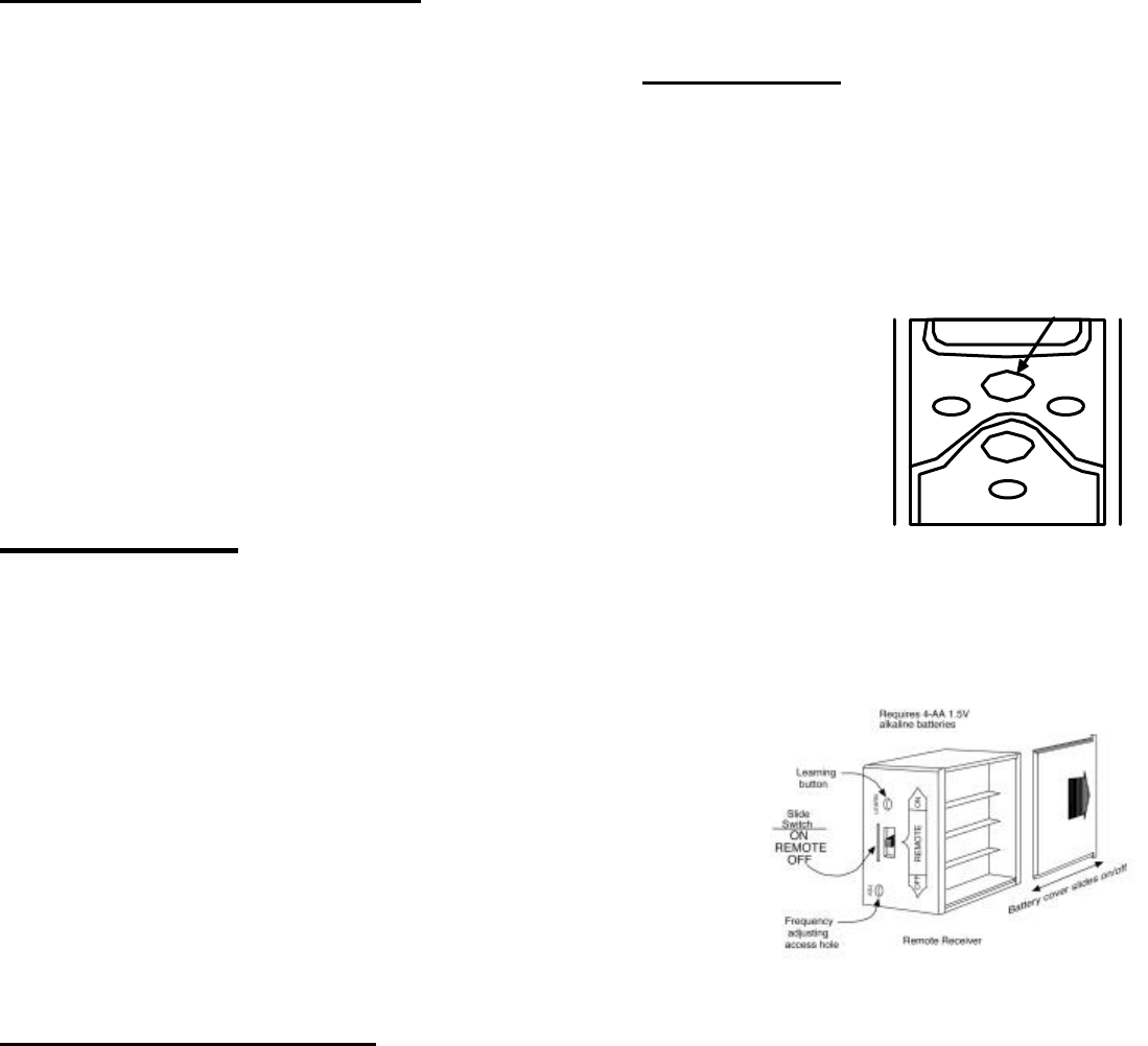
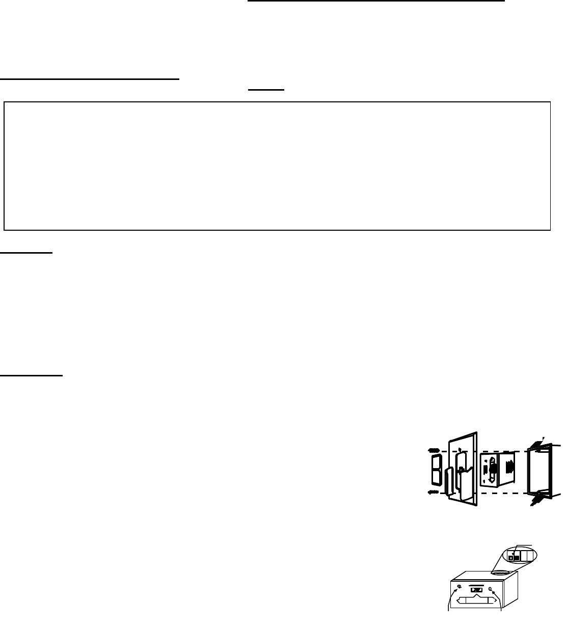
To attach wall mount cover Plate/Transmitter holder to Receiver box:
Position the receiver as shown in diagram to the left with lower tab on
wall mount cover plate into groove of receiver (Make sure ADJ hole
and LEARN hole on cover plate properly aligns with remote receiver)
Pull receiver up and snap into top tab of cover plate.
Position the wall mount cover plate so the word ON is facing up; then,
install the remote receiver into the plastic switch box using the two long
screws provided. Push the slide Button over the receiver slide switch only
after making sure the remote receiver has LEARNED the transmitter’s
security code (see MATCHING SECURITY CODES). NOTE: slide
Button covers both ADJ and Learn holes when properly installed.
NOTE: The remote receiver will only respond to the transmitter when the 3-position slide button
on the remote receiver is in the REMOTE position. If the system does not respond to the battery
transmitter on initial use, see MATCHING SECURITY CODES, and recheck battery positions in
the remote receiver.
Plastic Switch Box
Remote Receiver
Wall cover plate
& Transmitter holder
Receiver
Slide
Button
Remote Receiver
MILLIVOLT
VALVE
REMOTE
LEARN
ADJ.
Frequency adjusting
access hole Learning
button
Skytech 3001
REV 12/01
Page 6 of 8
HEARTH MOUNT
The remote receiver can be placed on the fireplace hearth or under the fireplace, behind the control access panel. Position where the ambient
temperature inside the receiver case does not exceed 1300 F.
NOTE: Black Slide Button is used for Hearth Mount applications.
WIRING INSTRUCTIONS
A qualified electrician or a gas technician who is familiar with the gas appliance and gas valves that will be operated by this remote should
install the remote control system. Incorrect wiring connections
WILL cause damage to the gas valve or electronic module operating the gas
appliance and may also damage the remote receiver.
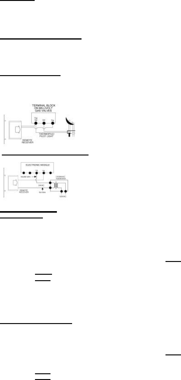
WIRING MILLIVOLT VALVES
The remote receiver is connected to the millivolt valve using the TH (thermostat) terminals on the terminal block on the millivolt gas valve.
Connect 18 gauge stranded or solid wires from the remote receiver to the gas valve.
Operation of the remote receiver is similar to that of a thermostat in that both turn the gas valve on and off
based on input signals. A thermostat’s input signals are different temperatures. The remote receiver’s input
signals come from the transmitter.
Connect each of the two wires leading from the TH and TH/TP terminals on the millivolt gas valve to either
of the two wire terminals on the remote receiver. Normally it does not matter which wires go to which
terminal.
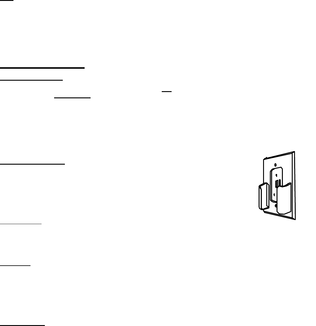
WIRING ELECTRONIC SPARK IGNITIONS
The remote control receiver can be connected, in series, to a 24VAC transformer to the TR (transformer)
terminal on the ELECTRONIC MODULE. Connect the hot wire from the 24VAC transformer to either of the
wire terminals on the remote receiver. Connect another wire (not included) between the other receiver wire
terminal and the TH (thermostat) terminal on the ELECTRONIC MODULE.
SYSTEM CHECK
MILLIVOLT VALVES
Light your gas appliance following the lighting instructions that came with the appliance. Confirm that the pilot flame is on; it must be in
operation for the main gas valve to operate.
• Slide the 3-position button on the remote receiver to the ON position. The main gas flame (i.e., the fire) should ignite.
• Slide the button to OFF. The flame should extinguish (the pilot flame will remain on).
• Slide the button to REMOTE (the center position), then press the MODE button on the transmitter to change the system to ON. The main
gas flame should ignite.
• Press the MODE button on the transmitter to change the system to OFF. The flame should extinguish (the pilot flame will remain on).
• Press the MODE button on the transmitter to change the system to THERMO. Advance the SET temperature on the transmitter to a
temperature of a least 20 F (10 C) above the ROOM temperature displayed on the LCD screen. With this manual setting, the normal
thermostatic cycle is overridden and the system flame will ignite. Set the SET temperature to at least 20 F (10 C) below the room
temperature and the system flame will extinguish in a few seconds. Thereafter, it should continue to cycle to on and off thermostatically
approximately every two minutes as the ROOM temperature changes, but only when the temperature differential between ROOM and
SET temperatures differ at least 20 F (1 0 C). The 2 0 F differential is the factory setting.
ELECTRONIC IGNITION SYSTEMS
• Slide the 3-position button on the remote receiver to the ON position. The spark electrode should begin sparking to ignite the pilot (the
pilot may ignite after only one spark). After the pilot flame is lit, the main gas valve should open and the main gas flam e should ignite.
• Slide the button to OFF. The main gas flame and pilot flame should BOTH extinguish.
• Slide the button to REMOTE (the center position), then press the MODE button on the transmitter to change the system to ON. The spark
electrode should begin sparking to ignite the pilot. After the pilot is lit, the main gas valve should open and the main gas flame should
ignite.
• Press the MODE button on the transmitter to OFF. The main gas flame and pilot flame should BOTH extinguish.
• Press the MODE button on the transmitter to change the system to THERMO. Advance the SET temperature on the transmitter to a
temperature of at least 20 F (10 C) above the ROOM temperature displayed on the LCD screen. With this manual setting the normal
thermostatic cycle is overridden and the system flame will ignite. Set the SET temperature to at least 20 F (10 C) below the room
temperature and the system flame will extinguish in a few seconds. Thereafter, it should continue to cycle to on and off thermostatically
Skytech 3001
REV 12/01
Page 7 of 8
approximately every two minutes as the ROOM temperature changes, but only when the temperature differential between ROOM and
SET temperatures differ at least 20 F (1 0 C). (The 2 0 F differential is the factory setting).
TIMER
The countdown timer will operate in either the manual ON or THERMO mode. Once the appliance is in an operating mode, set the countdown
timer to turn off in 15 minutes. The timer function will allow operation to continue until the countdown “time” on the LCD screen expires. After
15 minutes elapses, the system should turn OFF.
If you have any problems with operation, recheck you connections and ensure transmitter batteries are fully charged. If no problem is found,
contact the dealer where you purchased your appliance/remote control.
GENERAL INFORMATION
MATCHING SECURITY CODES
Each transmitter can use one of 1,048,576 unique security codes. It may be necessary to program the remote receiver to LEARN the security
code of the transmitter upon initial use, if batteries are replaced, or if a replacement transmitter is purchased from your dealer or the factory.
When matching security codes, be sure slide button on the receiver is in the REMOTE position; the code will NOT “LEARN” if the slide switch
is in the ON or OFF position. Program the remote receiver to LEARN a new security code by pushing in the LEARN button on the top of the
remote receiver and then pressing the MODE button on the transmitter. A change in the beeping pattern, at the receiver, indicates the
transmitter’s code has been programmed into the receiver. When an existing receiver is matched to a new transmitter, the new security code
will override the old one.
The microprocessor that controls the security code matching procedure is controlled by a timing function. If you are unsuccessful in matching
the security code on the first attempt, wait 1-2 minutes before trying again – this delay allows the microprocessor to reset its timer circuitry –
and try up to two or three more times.
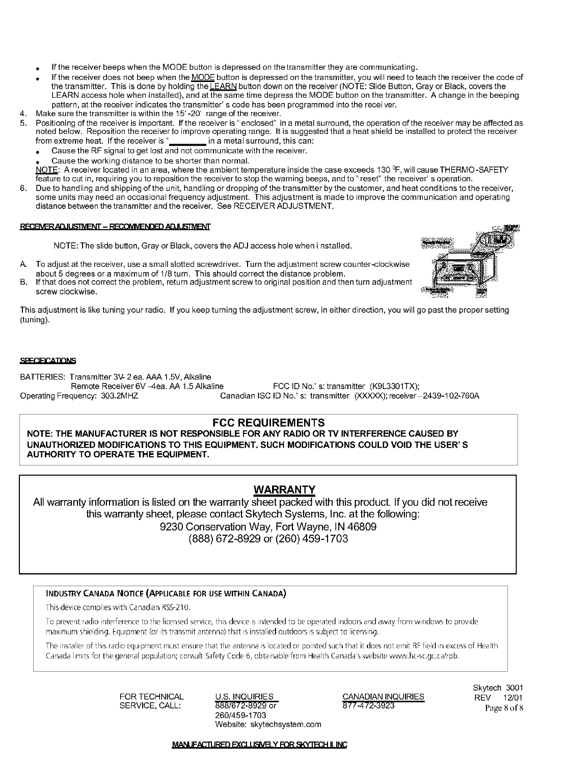
TRANSMITTER WALL BRACKET
The transmitter can be hung on a wall using the bracket provided. Locate the bracket on an inside
wall sufficiently far away from direct sources of heat such as a fireplace, incandescent lighting, or
sunlight so it detects ambient room temperatures, not a single heat source. If the bracket is
installed on a solid wood wall, drill 1/8” pilot holes and install with the screws provided. If it is installed
on a plaster/wallboard wall, first drill two 1/4” holes into the wall, then use a hammer to tap in the two
plastic wall anchors flush with the wall, then install the screws provided. Place hole cover label over the
center holes.
THERMO FUNCTION
When the transmitter is in the THERMO mode, it should be kept away from direct sources of heat such as fireplaces, incandescent lighting,
and direct sunlight. Leaving the transmitter in direct sunlight, for example, will cause its heat-sensing diode to read the room temperature
higher than it actually is; if in THERMO mode, it may not turn on the appliance even if the ambient ROOM temperature is below the SET
temperature.
BATTERY LIFE
Life expectancy of alkaline batteries in the SKYTECH 3301 should be at least 12 months. Check all batteries annually. When the Transmitter
or Wall Transmitter no longer operates the receiver from a distance it did previously (i.e., the transmitter’s range has decreased) or the remote
receiver does not function at all, the batteries should be checked. It is important that the remote receiver batteries are fully charged, providing
a combined output voltage of at least 5.3 volts. The length of the wire between the remote receiver and the gas valve directly affects the
operating performance of the remote system. The longer the wire, the more battery power is required to deliver signals between the remote
receiver and the gas valve. The Transmitter or Wall Transmitter should operate with as little as 2.5 volts battery power, Measuring at the (2)
1.5 volt batteries.
TROUBLE SHOOTING
Should you encounter problems with your fireplace system, the problem may be with the fireplace itself or it could be with the SKYTECH
remote control. Review the fireplace manufacturer’s operation manual to make sure all connections are properly made. Then check the
operation of the SKYTECH remote in the following manner:
1. Make sure receiver batteries are installed properly. If one battery is installed backward, receiver will not operate in remote mode. Be sure
battery output is 2.5 volts or more. (Slide switch is independent of battery condition.)
2. Be sure the transmitter’s batteries are properly installed and that the battery output is 2.5 V or more.
3. Check to make sure the transmitter is communicating with the receiver.

Federal Communication Commission Interference Statement
This equipment has been tested and found to comply with the limits for a Class B digital device, pursuant
to Part 15 of the FCC Rules. These limits are designed to provide reasonable protection against harmful
interference in a residential installation. This equipment generates, uses and can radiate radio frequency
energy and, if not installed and used in accordance with the instructions, may cause harmful interference
to radio communications. However, there is no guarantee that interference will not occur in a particular
installation. If this equipment does cause harmful interference to radio or television reception, which can
be determined by turning the equipment off and on, the user is encouraged to try to correct the
interference by one of the following measures:
• Reorient or relocate the receiving antenna.
• Increase the separation between the equipment and receiver.
• Connect the equipment into an outlet on a circuit different from that to which the receiver is
connected.
• Consult the dealer or an experienced radio/TV technician for help.
This device complies with Part 15 of the FCC Rules. Operation is subject to the following two
conditions: (1) This device may not cause harmful interference, and (2) this device must accept
any interference received, including interference that may cause undesired operation.
Caution:. Any changes or modifications not expressly approved by the party responsible for compliance
could void the user's authority to operate this equipment.