Skytech II AFTS1TX Transmitter User Manual 5 User s manual
Skytech II, Inc. Transmitter 5 User s manual
5.User's manual

FUNCTIONAL SPECIFICATION
SPTS-H/L-TH TRANSMITTER
Revision History
Rev. 0: Initial Release. M.R. 5/26/2011.
Rev. 1: Clarified cycling between settings when in Day/Time and Program Setup modes (wait 5-seconds)
and clarified Time setting sequence (advance in 1-minute increments, hour advances every 60 minutes,
AM/PM cycle every 12-hours). M. Rogers 6/1/2011.
Rev. 2: Updated Touch-Screen LCD and Button layout graphic. Changed MODE Button to MODE/SET
Button, added use of MOD/SET Button to accept setting adjustments, increased automatic acceptance time
from 5 to 15 seconds. Separated hour and minute time settings with addition of SET button. Added
MODE/SET button to Program mode deactivation. Changed temperature unit type selection to two button
press (UP and DOWN) to agree with other model transmitters, clarified SWING temperature setting and
display. Changed MAIN flame displays to FLAME-A Icon & clarified FLAME Zone display under
Program ON operation. Removed references to FLAME Icon in MODE Zone display. Changed SET
TEMP to 2-second automatic. M. Rogers 6/13/2011.
Rev. 3: Added specific model number. M. Rogers 12/19/2011.
Rev. 4: Clarified Low Battery Indicator voltage limit (5.0V), removed Manual OFF from communication
safety feature. M. Rogers 12/20/2011.
Rev. 5: Added factory default thermostat SET TEMPERATURE, Clarified LCD display in Flame-A
adjustment mode, clarified backlight requirement during Child-Lock operation. M. Rogers 12/21/2011.
Rev. 6: Clarified Program ON flame zone display (THERMO ON vs THERMO OFF). M. Rogers
12/27/2011.
Rev. 7: Added Thermostat Disable Feature & Room Temperature Limit Feature. M. Rogers 3/22/2012.
Rev. 8: Clarified Thermostat Disable Feature (TX must be in MANUAL OFF Mode to activate/deactivate
feature. M. Rogers 3/27/2012
Objective
Define basic construction, touch-screen LCD & button layout, and operational parameters for a
wireless transmitter to operate the AF-4000MOD-1 ignition control module.
Basic Construction
• Transmitter body should be the same construction as current production model SKY-
5301P.
• Touch-Screen LCD and three push buttons will allow input from users.
• LCD screen will provide system status & input feedback to user.
• Blue Backlight will illuminate LCD screen for 5 seconds after any user input.
• Powered via four AAA sized batteries (6V nominal) with LOW BATTERY
INDICATOR (5.0V).
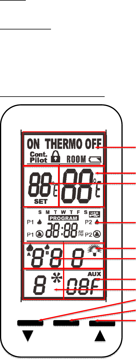
Touch-Screen LCD and Button Layout
MODE/SET
MODE Zone
SET TEMP Zone
ROOM TEMP Zone
LIGHT Zone (Unused)
FAN Zone (Unused)
TIME/PROG Zone
AUX Zone (Unused)
FLAME Zone
DOWN Button
MODE/SET Button
UP Button

Functional Description
Note: All function adjustments will be automatically accepted 15-seconds after pressing a given
touch zone or button. The user may press the MODE/SET button to immediately accept the
adjustment manually.
Day and Time Display
• The current day of week and time of day will be continuously displayed in the
TIME/PROG Zone (except during Setup operations).
• The day of week will be displayed as one of the following: S, M, T, W, T, F, S
• The time of day will be in 12-hour AM, 12-hour PM format. Midnight will be displayed
as 12:00am.
• Day/Time Setup:
o Press and hold the MODE Zone or the MODE/SET Button for 5 seconds to enter
Day/Time Setup.
o Press the UP or DOWN Buttons to adjust the day of week (press the MODE/SET
Button or wait for 15 seconds for adjustment to be accepted, then enter hour of
day adjustment).
o Press the UP or DOWN Buttons to adjust the hour of the day. The time will
advance in 1-hour increments; AM and PM will change when the hour advances
to 12:00 midnight and 12:00 noon respectively (press the MODE/SET Button or
wait for 15 seconds for adjustment to be accepted, then enter minute of hour
adjustment).
o Press the UP or DOWN Buttons to adjust the minute of the hour. The time will
advance in 1-minute increments (press the MODE/SET Button or wait for 15
seconds and the transmitter will exit Day/Time Setup and return to normal
operation).
o LCD Displays – when in Day/Time Setup:
MODE Zone: Blank
ROOM TEMP Zone: Blank
SET TEMP Zone: Bank
LIGHT Zone: Blank
FAN Zone: Blank
TIME/PROG Zone: Day of Week, or Time of Day will Flash
AUX Zone: Blank
FLAME Zone: Blank
Modes of Operation
Operation modes:
• MANUAL OFF
• MANUAL ON
• THERMOSTAT
The modes may be cycled in the order above by pressing the MODE Zone or the MODE/SET
Button.
MANUAL OFF Mode:
• Transmits flame OFF command.
• LCD Displays:
o MODE Zone: OFF is displayed
o ROOM TEMP Zone: Measured temperature is displayed
o SET TEMP Zone: Blank
o LIGHT Zone: Blank
o FAN Zone: Blank
o TIME/PROG Zone: Current day indicator and current time is displayed
o AUX Zone: Blank
o FLAME Zone: Blank
MANUAL ON Mode:
• Transmits flame ON command
• LCD Displays:
o MODE Zone: ON is displayed
o ROOM TEMP Zone: Measured temperature is displayed
o SET TEMP Zone: Blank
o LIGHT Zone: Blank
o FAN Zone: Blank
o TIME/PROG Zone: Current day indicator and current time is displayed
o AUX Zone: Blank
o FLAME Zone: the FLAME-A Icon is displayed
THERMOSTAT Mode:
• Will cycle flame on and off based on room and set temperatures. Will transmit ON
command if SET TEMP (+SWING) is higher than ROOM TEMP and will transmit OFF
command if SET TEMP (-SWING) is lower than ROOM TEMP.
• Built-in thermostat will measure room temperature.
• All programming should be written for deg. F scale and converted to deg. C when
selected.
• Temperatures may be displayed in degrees F (factory default) or degrees C. Press the UP
and DOWN Buttons simultaneously to change between degrees F and C.
• SET TEMP: While in THERMOSTAT mode, press the UP or DOWN Button to change
the SET TEMP (45-99 deg. F, 7-37 deg. C); the new set temperature will automatically
be accepted after 2 seconds. The factory default SET TEMP is 45 deg. F.
• SWING Temperature:
o Factory default is 2 degrees F (1 deg. C).
o Press and hold the SET TEMP Zone for 5 seconds to enter SWING Adjustment,
and press the UP and DOWN Buttons to adjust the SWING temperature from 3
degrees F (2 degrees C) or to 1 deg. F (still 1 deg. C) (press the MODE/SET
Button or wait for 15 seconds for the new setting to be accepted).
o LCD Display - When in SWING Adjustment:
MODE Zone: Blank
ROOM TEMP Zone: Blank
SET TEMP Zone: S1, S2, or S3 (number equals swing temperature) in
place of the SET temperature
LIGHT Zone: Blank
FAN Zone: Blank
TIME/PROG Zone: Blank
AUX Zone: Blank
FLAME Zone: Blank
• THERMOSTAT OFF LCD Displays:
o MODE Zone: THERMO and OFF is displayed
o ROOM TEMP Zone: Measured temperature is displayed
o SET TEMP Zone: SET TEMP is displayed
o LIGHT Zone: Blank

o FAN Zone: Blank
o TIME/PROG Zone: Current day indicator and current time is displayed
o AUX Zone: Blank
o FLAME Zone: Blank
• THERMOSTAT ON LCD Displays:
o MODE Zone: THERMO and ON are displayed
o ROOM TEMP Zone: Measured temperature is displayed
o SET TEMP Zone: SET TEMP is displayed
o LIGHT Zone: Blank
o FAN Zone: Blank
o TIME/PROG Zone: Current day indicator and current time is displayed
o AUX Zone: Blank
o FLAME Zone: The FLAME-A Icon is displayed
Thermostat Disable Feature
• The Thermostat Mode (described above) may be disabled for applications where a
thermostat is not allowed or undesirable. When Thermostat Mode is Disabled:
o The Modes of operation will cycle between MANUAL ON and MANUAL OFF
(omitting THERMO).
o Program Operation (described below) is also disabled.
o The SET TEMP zone will be blank.
o The room temperature will still be measured & displayed in the ROOM TEMP
Zone.
o The TIME/PROG zone will continue to display the Clock and Day of week, but
none of the icons associated with Program Mode will be displayed.
• To disable or re-enable the Thermostat, the transmitter must be in MANUAL OFF Mode,
then press and hold the SET TEMP Zone and the DOWN Button simultaneously for 10-
seconds. The entire contents of the LCD screen will flash 3-times (0.5-seconds OFF, 0.5-
seconds ON) to indicate the change has been made.
Program Operation
• Press the TIME/PROG Zone to activate or deactivate Program Operation. Pressing the
MODE Zone or the MODE/SET Button will also deactivate Program Operation. When
Program Operation is deactivated, the transmitter will return to MANUAL OFF Mode.
• Program Operation will cycle fireplace ignition ON and OFF based on time settings (2
weekend periods and 2 weekday periods) and thermostat settings. Reference program
operation for current production model 5301P for complete description of operation and
factory defaults. Press the MODE/SET Button or wait for 15 seconds to advance to each
subsequent program setting.
• To enter Program Setup, press and hold the TIME/PROG Zone for 5 seconds.
• Program OFF LCD Displays:
o MODE Zone: OFF
o ROOM TEMP Zone: Measured temperature is displayed
o SET TEMP Zone: Blank
o LIGHT Zone: Blank
o FAN Zone: Blank
o TIME/PROG Zone: Current day indicator, current time, and Program status (P1-
OFF or P2-OFF) is displayed
o AUX Zone: Blank
o FLAME Zone: Blank

• Program ON LCD Displays:
o MODE Zone: THERMO and either ON or OFF is displayed
o ROOM TEMP Zone: Measured temperature is displayed
o SET TEMP Zone: SET TEMP is displayed
o LIGHT Zone: Blank
o FAN Zone: Blank
o TIME/PROG Zone: Current day indicator, current time, and Program status (P1-
ON or P2-ON) is displayed
o AUX Zone: Blank.
o FLAME Zone:
If Thermostat is ON, the Flame-A Icon is displayed.
If Thermostat is OFF, display is blank.
Flame Adjustment
• Transmits either a HI command or a LO command to the control module to adjust the
flame height.
• While in MANUAL ON, THERMOSTAT ON, or PROGRAM ON modes, press the
FLAME Zone to enter Flame Adjustment, then press the UP or DOWN buttons to raise
and lower the flame. This command is transmitted at the same time the user is pressing
the UP or DOWN Button.
• LCD Displays: When in Flame-A adjustment mode, the Flame-A icon will flash in the
FLAME zone; when actually adjusting the flame, the direction of adjustment (HI or LO)
will be displayed:
o When raising the flame height with the UP button, the FLAME-A Icon and HI
will flash in the FLAME Zone.
o When lowering the flame height with the DOWN button, the FLAME-A Icon
and LO will flash in the FLAME Zone.
Continuous Pilot Operation
• To activate or deactivate the Continuous Pilot Feature, press and hold the MODE/SET
and UP Buttons simultaneously for 5 seconds.
• LCD Display: When activated, CONT. PILOT will be displayed in the MODE Zone.
Child-Lock Operation
• Child-Lock operation prevents any user input to the transmitter. No mode of operation or
feature may be adjusted when Child-Lock is activated. All automatic functions
(thermostat, program, etc.) will continue normally.
• To activate or deactivate the Child-Lock feature, press and hold the MODE/SET and
DOWN Buttons simultaneously for 5 seconds.
• LCD Display:
o When activated, the LOCK icon will appear in the MODE Zone.
o If any touch-zone or button is pressed when activated, the LCD backlight will
illuminate and the LOCK icon will flash for 5 seconds in the MODE Zone.
Communication Safety
• In manual ON, thermostat and program modes of operation, the transmitter will send a
communication safety transmission every 15-minutes. This signal is further processed by
the ignition control module to verify the transmitter is communicating properly.
Room Temperature Limit
• The Room Temperature Limit Shutdown feature will operate in MANUAL ON,
THERMOSTAT ON mode, and PROGRAM ON modes. If the room temperature reaches
95 deg. F or greater, the transmitter will automatically change to MANUAL OFF mode
and send a MANUAL OFF command to the control module. If the user turns the control
back ON and the room temperature is still 95F or greater, the transmitter will switch to
back manual OFF and send another OFF command the next time the transmitter reads &
updates the room temperature (2-minute update interval).