Skytech II REMOTION Transmiter User Manual 5 R2
Skytech II, Inc. Transmiter 5 R2
5.User manual R2

FUNCTIONAL SPECIFICATION
COPRECI “ReMotion” TRANSMITTER
Revision History
Rev. 0: Initial Release. M.R. 7/11/2012.
Rev. 1: Following customer review - Changed LCD indication (flashing indicator) for Thermostat Disable
and Program Disable Features; Changed factory default THERMO SET Temperature from 45-deg. F to 68-
deg. F. M.R. 7/13/2012.
Rev. 2: Changed number of LIGHT settings from 0-2 to 0-3 per customer request. M.R. 8/9/2012
Rev. 3: Removed Flame-A setting memory (RX restriction), added requirement for Continuous Pilot ON to
be default setting, added requirement for main flame to be ON when activating Continuous Pilot (RX
restriction), added Light/Fan/Aux disable features. M.R. 12/13/2012.
Rev. 4: Removed manual selection of Continuous Pilot Mode, specified Pilot Method for Manual,
Thermostat, and Program modes, changed reaction to 1st touch of LCD screen (will only illuminate
backlight – no reaction to associated Zone function). M.R. 12/21/2012.
Rev. 5: Made the factory default for FLAME B, FAN, LIGHTS, and Aux outputs “Disabled” and added
reference to “auxiliary module” when referencing these functions. M.R. 5/6/2013.
Objective
Define basic construction, touch-screen LCD & button layout, and operational parameters for a wireless
transmitter to operate the COPRECI “ReMotion” ignition control module & optional auxiliary module.
Basic Construction
• Transmitter body should be the same construction as current production model ReMotion TX.
• Touch-Screen LCD and three push buttons will allow input from users.
• LCD screen will provide system status & input feedback to user.
• Backlight will illuminate LCD screen for 5 seconds after any user input – the 1st touch of the LCD
screen will only illuminate the backlight (will not respond to associated zone function).
• Powered via four AAA sized batteries (6V nominal) with LOW BATTERY INDICATOR (5.0V).
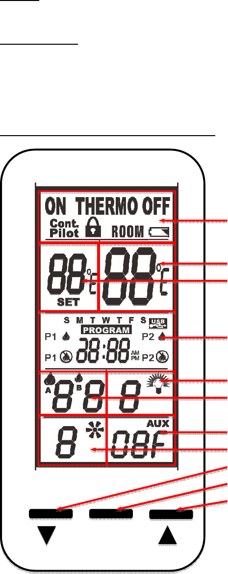
Touch-Screen LCD and Button Layout (not-to-scale)
MODE Zone
SET TEMP Zone
ROOM TEMP Zone
LIGHT Zone
FLAME Zone
TIME/PROG Zone
AUX Zone
FAN Zone
DOWN Button
MODE/SET Button
UP Button
MODE/SET

Functional Description
Note: All function adjustments will be automatically accepted 15-seconds after pressing a given
touch zone or button. The user may press the MODE/SET button to immediately accept the
adjustment manually.
Day and Time Display
• The current day of week and time of day will be continuously displayed in the
TIME/PROG Zone (except during Setup operations).
• The day of week will be displayed as one of the following: S, M, T, W, T, F, S
• The time of day will be in 12-hour AM, 12-hour PM format. Midnight will be displayed
as 12:00am.
• Day/Time Setup:
o Press and hold the MODE Zone for 5 seconds to enter Day/Time Setup.
o Press the UP or DOWN Buttons to adjust the day of week (press the MODE/SET
Button or wait for 15 seconds for adjustment to be accepted, then enter hour of
day adjustment).
o Press the UP or DOWN Buttons to adjust the hour of the day. The time will
advance in 1-hour increments; AM and PM will change when the hour advances
to 12:00 midnight and 12:00 noon respectively (press the MODE/SET Button or
wait for 15 seconds for adjustment to be accepted, then enter minute of hour
adjustment).
o Press the UP or DOWN Buttons to adjust the minute of the hour. The time will
advance in 1-minute increments (press the MODE/SET Button or wait for 15
seconds and the transmitter will exit Day/Time Setup and return to normal
operation).
o LCD Displays – when in Day/Time Setup:
MODE Zone: Blank
ROOM TEMP Zone: Blank
SET TEMP Zone: Bank
LIGHT Zone: Blank
FAN Zone: Blank
TIME/PROG Zone: Day of Week, or Time of Day will Flash
AUX Zone: Blank
FLAME Zone: Blank
Pairing
• To enter pairing mode press and hold the MODE/SET Button for 10-seconds.
• Transmitter will transmit a pairing signal for 20-seconds, then automatically exit pairing
mode and return to normal operation.
• LCD Displays – When pairing mode is activated:
o MODE Zone: Blank
o ROOM TEMP Zone: The letters “On” will flash.
o SET TEMP Zone: The letter “P” is displayed
o LIGHT Zone: Blank
o FAN Zone: Blank
o TIME/PROG Zone: Blank
o AUX Zone: Blank
o FLAME Zone: Blank

Modes of Operation
Operation modes:
• MANUAL OFF
• MANUAL ON
• THERMOSTAT (with optional PROGRAM Mode)
The modes may be cycled in the order above by pressing the MODE Zone or the MODE/SET
Button.
MANUAL OFF Mode:
• Transmits flame OFF command.
• Pilot Method: Intermittent Pilot Ignition (IPI)/Spark-to-Pilot only
(continuous/standing pilot not allowed)
o Pilot flame will be turned OFF
• LCD Displays:
o MODE Zone: OFF is displayed
o ROOM TEMP Zone: Measured temperature is displayed
o SET TEMP Zone: Blank
o LIGHT Zone: LIGHT and light setting level is displayed
o FAN Zone: Blank
o TIME/PROG Zone: Current day indicator and current time is displayed
o AUX Zone: AUX and AUX setting is displayed
o FLAME Zone: Blank
MANUAL ON Mode:
• Transmits flame ON command
• Pilot Method: Intermittent Pilot Ignition (IPI)/Spark-to-Pilot only
(continuous/standing pilot not allowed)
o Pilot flame will be ignited before turn Main Flame ON.
• LCD Displays:
o MODE Zone: ON is displayed
o ROOM TEMP Zone: Measured temperature is displayed
o SET TEMP Zone: Blank
o LIGHT Zone: LIGHT and light setting level is displayed
o FAN Zone: FAN and fan setting level is displayed
o TIME/PROG Zone: Current day indicator and current time is displayed
o AUX Zone: AUX and AUX setting is displayed
o FLAME Zone: A Flame Icon and flame setting level number is displayed
THERMOSTAT Mode:
• Will cycle flame on and off based on room and set temperatures. Will transmit ON
command if SET TEMP (+SWING) is higher than ROOM TEMP and will transmit OFF
command if SET TEMP (-SWING) is lower than ROOM TEMP.
• Built-in thermostat will measure room temperature.
• All programming should be written for deg. F and converted to deg. C when selected.
• Temperatures may be displayed in degrees F (factory default) or degrees C. Press the UP
and DOWN Buttons simultaneously to change between degrees F and C.
• SET TEMP: While in THERMOSTAT mode, press the UP or DOWN Button to change
the SET TEMP (45-90 deg. F, 7-32 deg. C); the new set temperature will automatically
be accepted after 2 seconds. The factory default SET TEMP is 68 deg. F.

• SWING Temperature: This model does not allow for SWING temperature adjustment.
This model utilizes thermostatic flame modulation that will modulation the main flame
based on the difference between room temperature and set temperature (see example
below).
o Important - factory SWING TEMPERATURE setting is 2 degrees. The
thermostatic flame modulation feature will not allow this SWING to be changed.
EXAMPLE:
Set Temperature Room Temp. Flame Level
74F OFF
73F Level 1
Set Temperature (72) 72F Level 2
71F (or less) Level 3
• Pilot Method: Continuous/Standing Pilot only (Intermittent Pilot Ignition
(IPI)/Spark-to-Pilot not allowed).
o Pilot flame will remain ON when Main Flame Cycles ON and OFF.
• Manual Flame Adjustment while in THERMOSTAT mode: If Flame-A is manually
adjusted while in thermostat mode, it will override the automatic flame setting until the
flame cycles off, then back ON thermostatically; when the flame cycles ON again,
automatic flame adjustment will resume. Automatic flame adjustment will also resume if
the operational mode is cycled out of, then back into THERMOSTAT mode or if the SET
temperature is changed.
• THERMOSTAT OFF LCD Displays:
o MODE Zone: THERMO and OFF is displayed
o ROOM TEMP Zone: Measured temperature is displayed
o SET TEMP Zone: SET TEMP is displayed
o LIGHT Zone: LIGHT and light setting level is displayed
o FAN Zone: Blank
o TIME/PROG Zone: Current day indicator and current time is displayed
o AUX Zone: AUX and AUX setting is displayed
o FLAME Zone: Blank
• THERMOSTAT ON LCD Displays:
o MODE Zone: THERMO and ON are displayed
o ROOM TEMP Zone: Measured temperature is displayed
o SET TEMP Zone: SET TEMP is displayed
o LIGHT Zone: LIGHT and light setting level is displayed
o FAN Zone: FAN and fan setting level is displayed
o TIME/PROG Zone: Current day indicator and current time is displayed
o AUX Zone: AUX and AUX setting is displayed
o FLAME Zone: A Flame Icon and flame setting level number is displayed
Thermostat Disable Feature
• The Thermostat Mode (described above) may be disabled for applications where a
thermostat is not allowed or undesirable. When Thermostat Mode is Disabled:
o The Modes of operation will cycle between MANUAL ON and MANUAL OFF
(omitting THERMO).
o Program Operation (described below) is also disabled.
o The SET TEMP zone will be blank.

o The room temperature will still be measured & displayed in the ROOM TEMP
Zone.
o The TIME/PROG zone will continue to display the Clock and Day of week, but
none of the icons associated with Program Mode will be displayed.
• To disable or re-enable the Thermostat, the transmitter must be in MANUAL OFF Mode,
then press and hold the SET TEMP Zone and the DOWN Button simultaneously for 10-
seconds. The LCD screen will go blank except either THERMO and OFF or THERMO
and ON will flash 3-times (0.5-seconds OFF, 0.5-seconds ON) to indicate the change has
been made.
Program Operation
• Press the TIME/PROG Zone to activate or deactivate Program Operation. Pressing the
MODE Zone or the MODE/SET Button will also deactivate Program Operation. When
Program Operation is deactivated, the transmitter will return to MANUAL OFF Mode.
• Program Operation will cycle fireplace ignition ON and OFF based on time settings (2
weekend periods and 2 weekday periods) and thermostat settings. Reference program
operation for current production model 5301P for complete description of operation and
factory defaults. Press the MODE/SET Button or wait for 15 seconds to advance to each
subsequent program setting.
• Pilot Method (same as Thermostat Mode): Continuous/Standing Pilot only
(Intermittent Pilot Ignition (IPI)/Spark-to-Pilot not allowed).
o Pilot flame will remain ON when Main Flame Cycles ON and OFF.
• To enter Program Setup, press and hold the TIME/PROG Zone for 5 seconds.
• Program OFF LCD Displays:
o MODE Zone: OFF
o ROOM TEMP Zone: Measured temperature is displayed
o SET TEMP Zone: Blank
o LIGHT Zone: LIGHT and light setting level is displayed
o FAN Zone: Blank
o TIME/PROG Zone: Current day indicator, current time, and Program status (P1-
OFF or P2-OFF) is displayed
o AUX Zone: AUX and AUX setting is displayed
o FLAME Zone: Blank
• Program ON LCD Displays:
o MODE Zone: THERMO and either ON or OFF is displayed
o ROOM TEMP Zone: Measured temperature is displayed
o SET TEMP Zone: SET TEMP is displayed
o LIGHT Zone: LIGHT and light setting level is displayed
o FAN Zone:
If Thermostat is ON, FAN and fan setting number is displayed
If Thermostat is OFF, display is blank.
o TIME/PROG Zone: Current day indicator, current time, and Program status (P1-
ON or P2-ON) is displayed
o AUX Zone: AUX and AUX setting is displayed
o FLAME Zone:
If Thermostat is ON, A Flame Icon and flame setting level number is
displayed.
If Thermostat is OFF, display is blank.
Program Disable Feature

• The Program Mode (described above) may be disabled for applications where a program
operation is not allowed or undesirable. When Program Mode is Disabled:
o The user will not be able to activate Program Mode
o The user will not be able to enter Program Setup or edit Program Mode settings.
o The TIME/PROG zone will continue to display the Clock and Day of week, but
none of the icons associated with Program Mode will be displayed.
• To disable or re-enable the Program Mode, the transmitter must be in MANUAL OFF
Mode, then press and hold the TIME/PROG Zone and the DOWN Button simultaneously
for 10-seconds. The LCD screen will go blank except either PROGRAM and OFF (OFF
display in MODE Zone) or PROGRAM and ON (ON display in MODE Zone) will flash
3-times (0.5-seconds OFF, 0.5-seconds ON) to indicate the change has been made.
Flame-A (or Main) Adjustment
• Transmits a flame height setting command to the control module to adjust the Flame-A
height.
• Available settings are 1-3 with a factory default of 3. Refer to the THERMOSTAT Mode
section for additional details on flame modulation in THERMOSTAT mode.
• While in MANUAL ON, THERMOSTAT ON, or PROGRAM ON modes, press the
FLAME Zone to enter Flame-A Adjustment, then press the UP or DOWN buttons to
raise and lower the flame; press the MODE/SET Button or wait for 15 seconds to accept
the new setting.
• LCD Display: When setting the Flame-A height, the Flame-A icon, and Flame-A setting
number will flash in the FLAME Zone.
Flame-B (or Rear) Adjustment
• This feature is omitted on this model.
• The Flame-B Icon is not displayed on the LCD screen
Light (or Ember) Adjustment
• Transmits a light setting command to the control module to adjust the light output level.
• Available settings are 0 (off) – 3 with a factory default of 0 (off).
• While in any mode of operation, press the LIGHT Zone to enter Light Adjustment, then
press the UP or DOWN buttons to raise or lower the light output; press the MODE/SET
Button or wait for 15 seconds to accept the new setting.
• LCD Displays:
o When raising or lowering the light output level with the UP or DOWN buttons,
the light icon and light setting number will flash in the LIGHT Zone.
Light (or Ember) Adjustment Disable Feature
• The Light Adjustment Feature (described above) may be enabled for applications where
an auxiliary module and electrical lighting is used.
• THE FACTORY DEFAULT IS DISABLED. When the Light Adjustment Feature is
Disabled:
o The LIGHT icon and setting number will not be displayed.
o No adjustment to the Light setting can be made.
o The LIGHT output may not be energized.
• To disable or re-enable the Light Adjustment Feature, the transmitter must be in
MANUAL OFF Mode, then press and hold the LIGHT Zone and the DOWN Button
simultaneously for 10-seconds. The LCD screen will go blank except either the LIGHT
Icon and OFF (OFF display in MODE Zone) or the LIGHT Icon and ON (ON display in

MODE Zone) will flash 3-times (0.5-seconds OFF, 0.5-seconds ON) to indicate the
change has been made.
Fan Adjustment
• Transmits a fan setting command to the control module to adjust the fan output level.
• Available settings are 0 (off) – 3 with a factory default setting of 2. If the user changes
the fan speed during operation, the control will remember and use the adjusted setting on
subsequent fan ON cycles (fan speed memory).
• While in Manual ON, THERMOSTAT ON, or PROGRAM ON modes, press the FAN
Zone to enter Fan Adjustment, then press the UP or DOWN buttons to increase or
decrease the fan output; press the MODE/SET Button or wait for 15 seconds to accept the
new setting.
• LCD Displays:
o When raising or lowering the fan output level with the UP or DOWN buttons, the
fan icon and fan setting number will flash in the FAN Zone.
Fan Adjustment Disable Feature
• The Fan Adjustment Feature (described above) may be enabled for applications where an
auxiliary module and electric fan is used.
• THE FACTORY DEFAULT IS DISABLED. When the Fan Adjustment Feature is
Disabled:
o The FAN icon and setting number will not be displayed.
o No adjustment to the Fan setting can be made.
o The FAN output will not be energized.
• To disable or re-enable the Fan Adjustment Feature, the transmitter must be in MANUAL
OFF Mode, then press and hold the FAN Zone and the DOWN Button simultaneously for
10-seconds. The LCD screen will go blank except either the FAN Icon and OFF (OFF
display in MODE Zone) or the FAN Icon and ON (ON display in MODE Zone) will flash
3-times (0.5-seconds OFF, 0.5-seconds ON) to indicate the change has been made.
AUX (or Cracker) Adjustment
• Transmits an AUX setting command to the control module to turn the AUX output ON or
OFF.
• While in any mode of operation, press the AUX Zone to enter AUX Adjustment, then
press the UP or DOWN buttons to turn the AUX output ON or OFF; press the
MODE/SET Button or wait for 15 seconds to accept the new setting.
• LCD Display:
o When adjusting the AUX output, AUX and AUX setting (ON or OFF) will flash
in the AUX Zone.
AUX (or Cracker) Adjustment Disable Feature
• The AUX Adjustment Feature (described above) may be enabled for applications where
an auxiliary module and suitable electronics output are used.
• THE FACTORY DEFAULT IS DISABLED. When the AUX Adjustment Feature is
Disabled:
o AUX and the setting will not be displayed.
o No adjustment to the AUX setting can be made.
o The AUX output may not be energized.
• To disable or re-enable the AUX Adjustment Feature, the transmitter must be in
MANUAL OFF Mode, then press and hold the AUX Zone and the DOWN Button

simultaneously for 10-seconds. The LCD screen will go blank except either AUX and
OFF (OFF display in MODE Zone) or AUX and ON (ON display in MODE Zone) will
flash 3-times (0.5-seconds OFF, 0.5-seconds ON) to indicate the change has been made.
Child-Lock Operation
• Child-Lock operation prevents any user input to the transmitter. No mode of operation or
feature may be adjusted when Child-Lock is activated. All automatic functions
(thermostat, program, etc.) will continue normally.
• To activate or deactivate the Child-Lock feature, press and hold the MODE/SET and
DOWN Buttons simultaneously for 5 seconds.
• LCD Displays:
o When activated, the LOCK icon will appear in the MODE Zone.
o If any touch-zone or button is pressed when activated, the LCD backlight will
illuminate and the LOCK icon will flash for 5 seconds in the MODE Zone.
Sensor Safety Override
• This feature is omitted on this model.
Communication Safety
• This feature is omitted on this model.
Room Temperature Limit
• The Room Temperature Limit Shutdown feature will operate in MANUAL ON,
THERMOSTAT ON mode, and PROGRAM ON modes. If the room temperature reaches
95 deg. F or greater, the transmitter will automatically change to MANUAL OFF mode
and send a MANUAL OFF command to the control module. If the user turns the control
back ON and the room temperature is still 95F or greater, the transmitter will switch to
back manual OFF and send another OFF command the next time the transmitter reads &
updates the room temperature (2-minute update interval).
FCC Compliance Statement:
This device complies with Part 15 of the FCC Rules. Operation is subject to the
following two conditions: (1) This device may not cause harmful interference, and (2)
This device must accept any interference received, including interference that may cause
undesired operation.
Note: The manufacturer is not responsible for any radio or TV interference caused by
unauthorized modifications to this equipment. Such modifications could void the user’s
authority to operate the equipment.
This device complies with Industry Canada licence-exempt RSS standard(s). Operation is
subject to the following two conditions: (1) this device may not cause interference, and (2)
this device must accept any interference, including interference that may cause undesired
operation of the device.
Le présent appareil est conforme aux CNR d'Industrie Canada applicables aux appareils
radio exempts de licence. L'exploitation est autorisée aux deux conditions suivantes : (1)
l'appareil ne doit pas produire de brouillage, et (2) l'utilisateur de l'appareil doit accepter
tout brouillage radioélectrique subi, même si le brouillage est susceptible d'en
compromettre le fonctionnement.