Skytech II STTX1071 RF Transmitter User Manual Sporting Clays Instruction Manual
Skytech II, Inc. RF Transmitter Sporting Clays Instruction Manual
(45264) UserMan
0
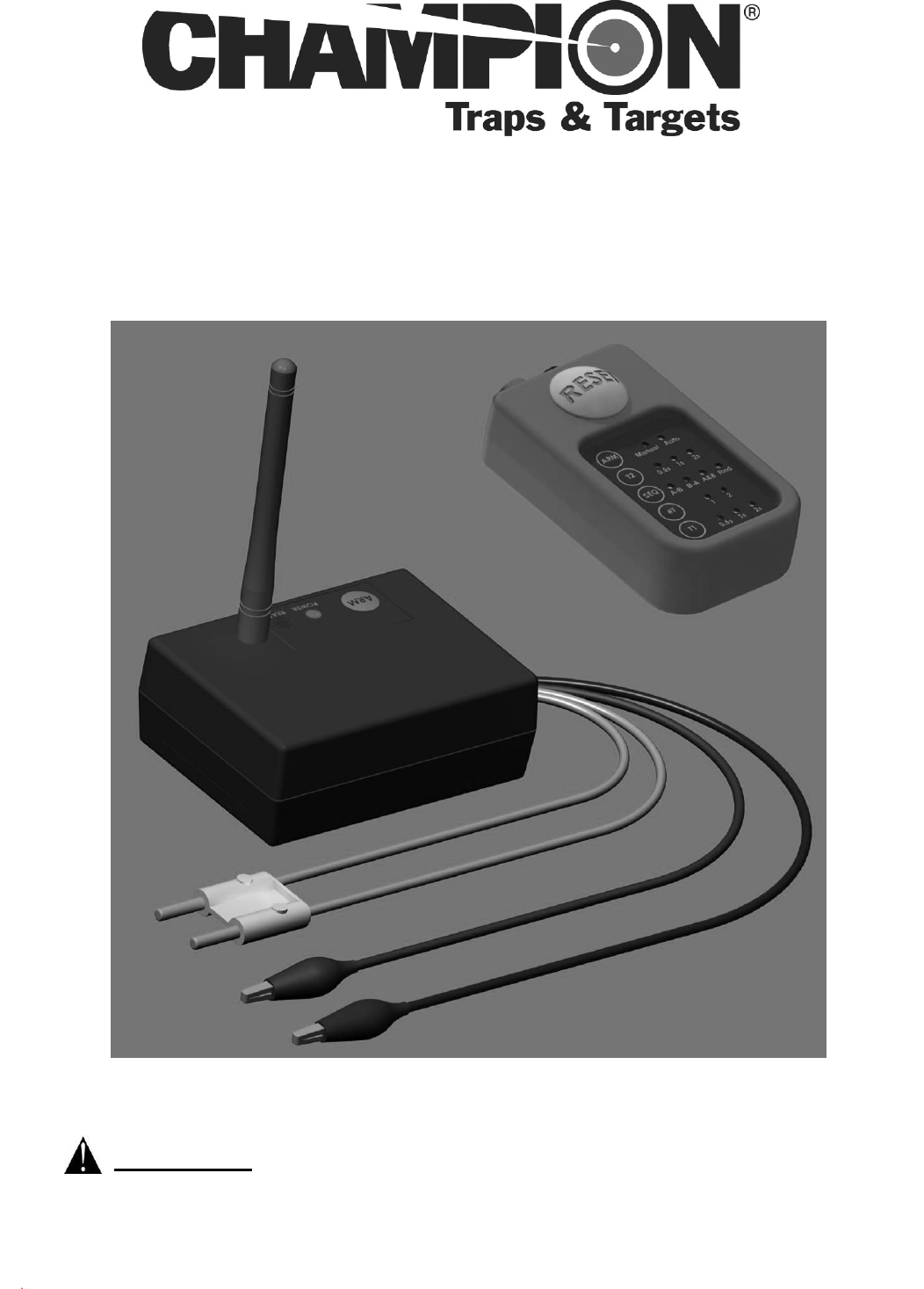
WIRELESS
VOICE RELEASE SYSTEM
Part Number: 45264
Instruction Manual
WARNING: TO AVOID SERIOUS INJURY OR PROPERTY
DAMAGE THOROUGHLY READ INSTRUCTIONS BEFORE USING.

1
Table of Contents
Section Page
I. Introduction / FCC Notice .................................................................... 1
II. Safety ................................................................................................. 2
III. Contents ............................................................................................. 3
IV. Features and Descriptions .................................................................. 4
V. Programming ......................................................................................................... 7
VI. Installation ........................................................................................... 8
VII. Operation…………………………………………………………………...10
VIII. Operational Examples…………………………………………………….12
IX. Troubleshooting ................................................................................ 14
Warranty and Contact Information .............................................................................. 16
I. Introduction
Congratulations on the purchase of your new Champion® Wireless Voice Release System.
The Champion® Wireless Voice Release System is an optional accessory for use with all
Champion® Easybird® full automatic traps (Auto-Feed, 6 Packer & Doubles), SST and 180-
Sporter traps.
Features of the Champion® Wireless Voice Release system include:
* Battery powered hand-held transmitter, high impact plastic case
* Up to 100 yard transmission range
* Single release system is upgradable to a double system by purchasing a 2nd Receiver
* Adjustable to match cycle time of different trap machines
* Quick and easy installation
FCC NOTICE:
This equipment has been tested and found to comply with the limits for a Class B digital device, pursuant to Part
15 of the FCC Rules. These limits are designed to provide reasonable protection against harmful interference in a
residential installation. This equipment generates uses and can radiate radio frequency energy and, if not
installed and used in accordance with the instructions, may cause harmful interference to radio communications.
However, there is no guarantee that interference will not occur in a particular installation. If this equipment does
cause harmful interference to radio or television reception, which can be determined by turning the equipment off
and on, the user is encouraged to try to correct the interference by one or more of the following measures:
Reorient or relocate the receiving antenna.
Increase the separation between the equipment and receiver.
Connect the equipment into an outlet on a circuit different from that to which the receiver is connected.
Consult the dealer for help.
This device complies with Part 15 of the FCC Rules. Operation is subject to the following two conditions:
1) This device may not cause harmful interference, and
2) This device must accept any interference received, including interference that may cause undesired operation.
Making any changes or modifications not expressly approved by the manufacturer may void the user’s authority to
operate this device.
FCC ID: K9LSTTX1071 IC: 2439A-STTX1071

2
II. Safety
WARNING: THOROUGHLY READ INSTRUCTIONS BEFORE
INSTALLING OR OPERATING THE WIRELESS VOICE RELEASE
SYSTEM!
MAKE SURE TRAP IS SAFELY UNCOCKED BEFORE MOVING IN
FRONT OF THE TRAP. ACCIDENTAL RELEASE OF THE TARGET
AND/OR THROWING ARM CAN CAUSE SERIOUS INJURY OR DEATH!
BEFORE INSTALLING THE WIRELESS VOICE RELEASE SYSTEM ON
THE TRAP, MAKE SURE THAT THE THROWING ARM IS IN THE
UNCOCKED POSITION, THE TRAP IS IN THE OFF POSITION AND THE
TRAP IS DISCONNECTED FROM THE BATTERY.
ALL PERSONNEL OPERATING THE TRAP SHOULD BE THOROUGHLY
FAMILIAR WITH THE OPERATING INSTRUCTIONS AND THE SAFETY
ISSUES RELATING TO THE TRAP.
DO NOT LEAVE TRAP IN THE COCKED POSITION. ACCIDENTAL
RELEASE OF THE THROWING ARM CAN OCCUR.
DO NOT STAND IN FRONT OF THE TRAP WHEN IT IS IN THE COCKED
POSITION.
KEEP HANDS AND BODY AWAY FROM THE TRAP AND THROWING
ARM PATH WHILE THE TRAP IS OPERATING.
WHEN TRANSMITTER IS IN AUTO MODE AND ARMED, ANY LOUD
NOISE MAY ACTIVATE RELEASE SEQUENCE AND LAUNCH A
TARGET. DO NOT ARM TRANSMITTER UNTIL SHOOTER IS READY
TO LAUNCH A TARGET.
WARNING: FAILURE TO FOLLOW SAFETY RULES CAN RESULT
IN SERIOUS INJURY OR DEATH!
3
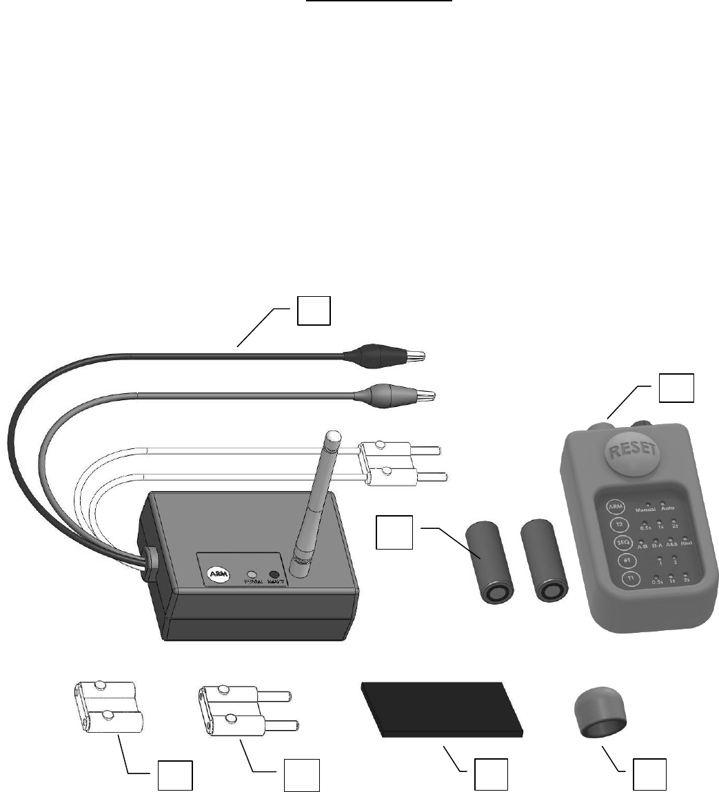
III. Contents
A – Receiver (Attach included antenna to top of receiver)
B – Sound-Activated Transmitter
C – Two AAA/1.5V Batteries for Transmitter
D – Trap Connector
E – Foot Pedal Connector
F – Adhesive Velcro Mounting Pad
G – Foam Microphone Wind Filter
(Fits over microphone on transmitter if needed for windy conditions)
A
B
D
C
E
F
G
4
IV. Features and Descriptions
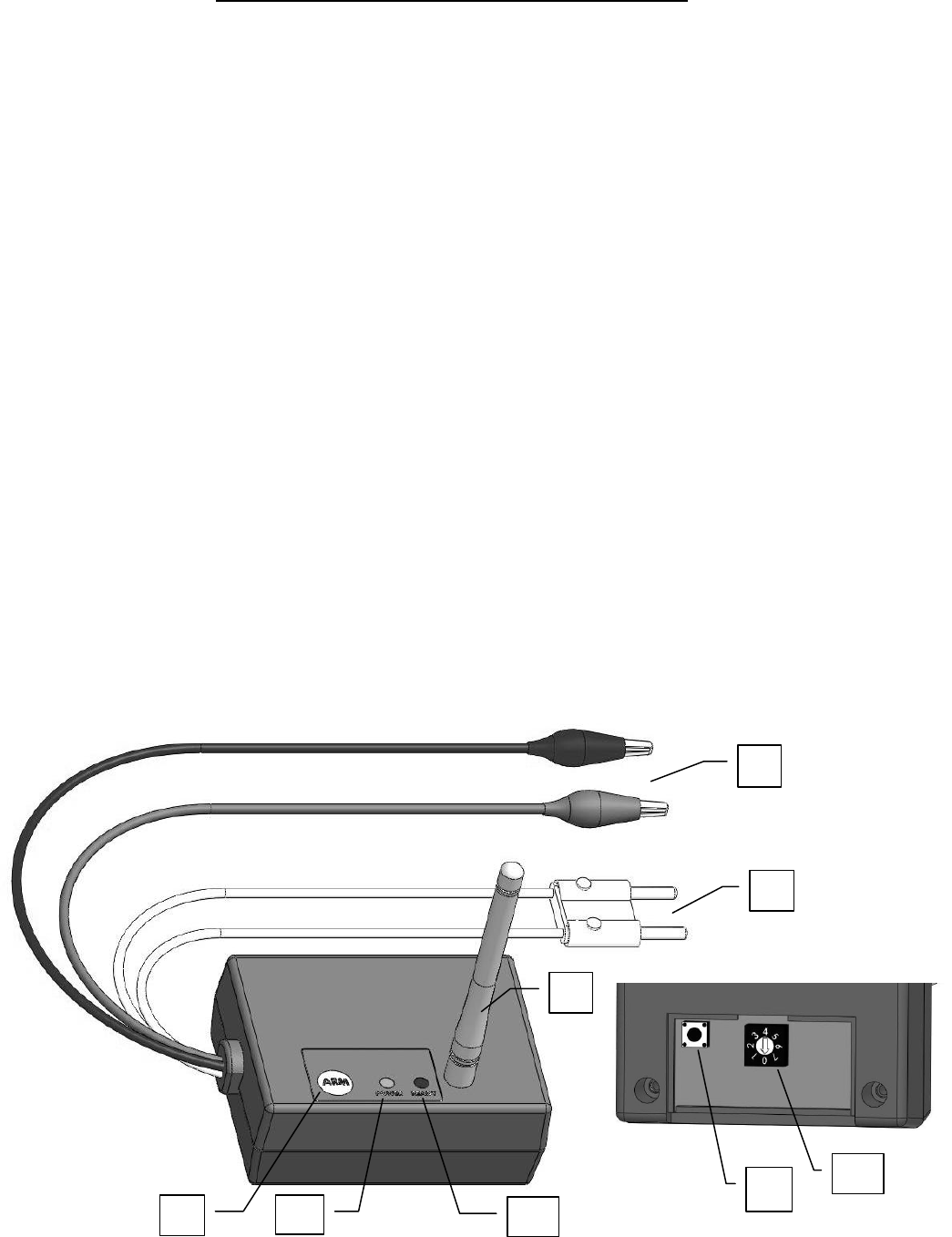
Receiver Unit
A - ARM Button:
o Press the ARM button to allow the receiver to accept transmitter commands
and enable receiver output (arm).
o Press the ARM button again to prevent the receiver from accepting
transmitter commands and disable the receiver output (disarm).
B - POWER LIGHT (Green):
o Illuminates continuously when receiver is connected to 12V power.
C - READY LIGHT (Red):
o Illuminates continuously when receiver is armed.
o Flashes when receiver is in “Learn” mode
D - REMOVABLE ANTENNA: Must be attached for proper operation
E - 12V POWER CONNECTIONS (Red and Black wires):
o Red wire clip connects to positive (+) terminal on 12V battery
o Black wire clip connects to negative (-) terminal on 12V battery
F - OUTPUT CONNECTOR (White wires and connector):
o Connects to foot pedal or hand release cable for trap
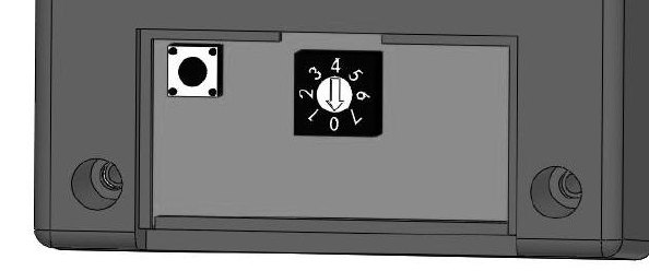
Inside Controls (remove bottom panel):
G - PROGRAMMING BUTTON:
o Press button to enter LEARN mode. The LEARN mode will automatically
cancel after 30 seconds if no transmission is received.
H - ACTIVATION ADJUSTMENT DIAL:
o Adjust for how long output relay will be activated (.5 to 3 sec)
A
B
D
E
F
C
H
G
5
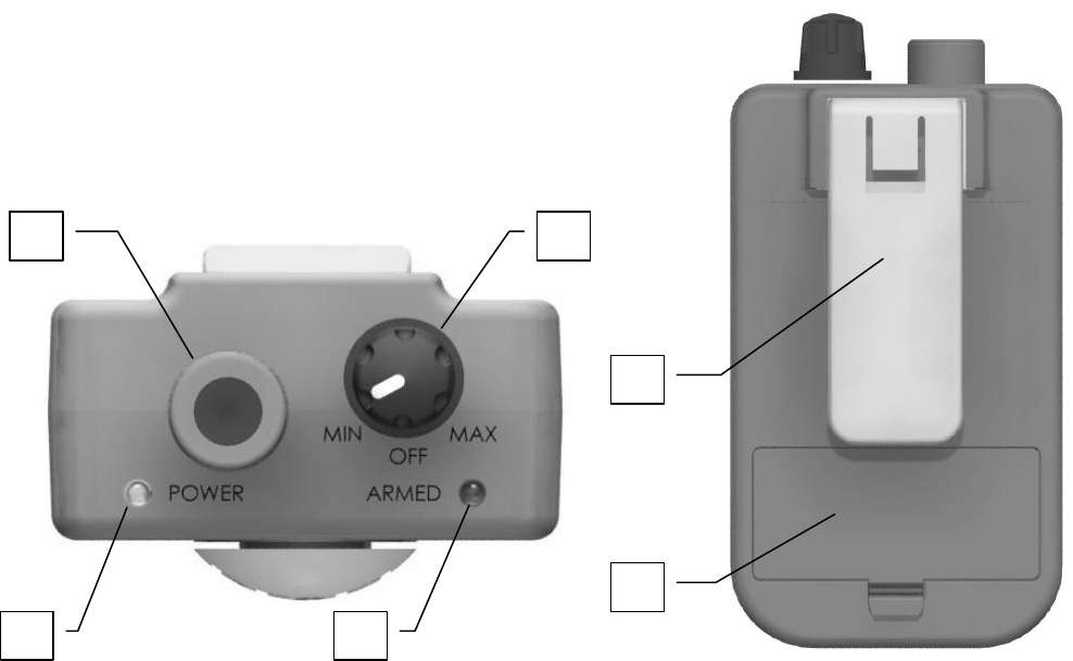
Sound Activated Remote Transmitter
TOP
A – ON/OFF & MICROPHONE DIAL:
o Powers transmitter ON/OFF and illuminates power light
o Adjusts microphone sensitivity from 100 db to 80 db. Midrange position
starting point. Clockwise will increase microphone sensitivity (quieter sound
will activate unit). Transmitter activated by loudness of ANY sound.
o Must be set to OFF when not in use to conserve battery life.
B – MICROPHONE
o To ensure optimum performance keep microphone clear of obstructions such
as clothing.
C – POWER LIGHT (Green):
o Green LED flashes at a rate of 1 second on and 1 second off when
transmitter is powered on and at a rate of 0.5 seconds on and 0.5 seconds off
when transmitter battery is low (active only when transmitter is turned on).
D – ARMED LIGHT (Red):
o Manual mode: Illuminates for 2 seconds when reset button pressed and unit
sends signal to receiver(s)
o Auto mode: Flashes at a rate of 1 second on and 1 second off when set to
auto mode and reset button is pushed (unit armed). Illuminates for 2
seconds when sound command registers and unit sends release signal to
receiver(s).
Back
E – BELT/POCKET CLIP:
F – BATTERY COMPARTMENT COVER:
o Remove to replace batteries
A
C
B
D
E
F
6
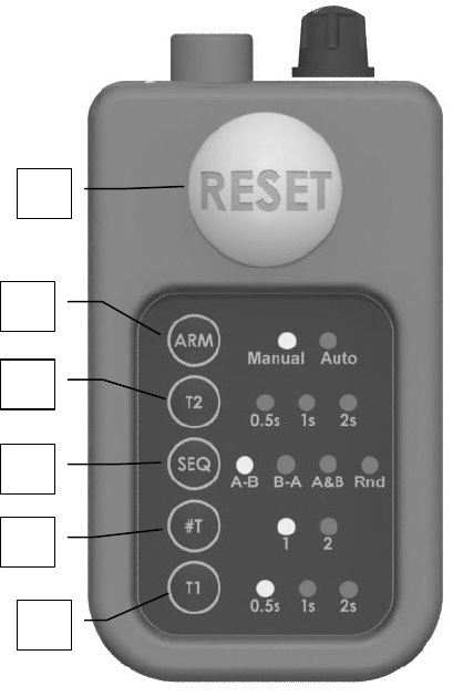
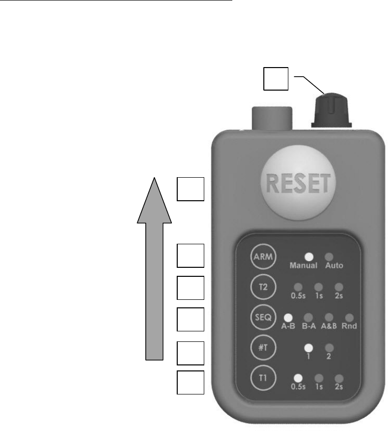
Front
G – T1
o Press T1 to select the desired time delay (in seconds) when release signal
sent to first receiver after release sequence is started
H - #T
o Press #T to select number of traps in use
J – SEQ
o Press SEQ to select trap release sequence.
A-B: If #T is 1 then release signal sent to receiver A.
If #T is 2 then release signal sent to A then B.
B-A: If #T is 1 then release signal sent to receiver B.
If #T is 2 then release signal sent to B then A.
A&B: If #T is 1 then this setting unavailable.
If #T is 2 then release signal sent to A&B.
Rnd: If #T is 1 then release signal randomly sent to
either A or B.
If #T is 2 then release signal randomly selects
A-B, B-A or A&B.
K – T2
o Press T2 to select the desired time delay (in
seconds) when release signal sent to second
receiver after release signal sent to first receiver
(disabled if SEQ set to A+B).
L - ARM
o Press ARM to select Manual or Auto release.
o Manual mode: Press RESET to start release sequence and send release signal
to receiver(s)
o Auto mode: when system is armed a voice/sound command will start release
sequence and send release signal to receiver(s)
M- RESET
o Manual mode: Press RESET to start release sequence and send release signal
to receiver(s)
o Auto mode: Press RESET to arm system. System now ready to accept
voice/sound command. Voice/sound command will start release sequence
and send release signal to receiver(s). Adjust microphone sensitivity dial if
receiver(s) do not activate. Press RESET again to disarm system.
(Once a voice/sound command is received, the microphone will be
deactivated for 4 seconds if #T is set to 1, and 6 seconds if #T is set to 2)
LED display will illuminate when any setting button is pressed and automatically
turn off after 5 seconds to conserve battery power.
All user settings are retained after the on/off microphone dial is turned off.
Pushing any button while in auto mode will disarm unit.
G
M
L
K
J
G
H
M

7
V. Programming
Programming Receiver with Sound Activated Remote Transmitter
Before operation each receiver will need to be programmed to the transmitter being used.
1. Install the AAA 1.5V Batteries in the transmitter if they are not installed. Remove
battery compartment cover, insert batteries and replace battery cover. Turn transmitter on
(green LED will flash slowly).
2. Connect receiver to 12V Battery, Red clip connects to positive (+), Black clip connects
to negative (-). If the battery terminals are too big to connect the clips to, first connect
the trap power clips to the battery (trap power switch set to OFF), then connect the
receiver power clips to the trap power clips. Green POWER light turns on.
3. Remove bottom panel of receiver and press the PROGRAM button to enter LEARN
mode. READY light on top of receiver flashes at rate of one (1) flash per second to
indicate receiver is ready to learn transmitter’s security code and trap ID (A or B) from
push button transmitter. The LEARN mode will automatically cancel after 30 seconds if
no transmission is received.
4. Press and hold the RESET button on the transmitter for 6 seconds. All lights on front
panel will turn off and only #T and SEQ lights will illuminate. The transmitter is now in
programming mode.
5. Press the SEQ button on the transmitter until A-B is lit and then press the RESET
button to learn the transmitter’s security code and designate the receiver as receiver A OR
press the SEQ button on the transmitter until B-A is lit and then press the RESET button
to learn the transmitter’s security code and designate the receiver as receiver B.
6. READY light on receiver flashes at a rate of four (4) flashes per second for three (3)
seconds to indicate that the receiver has learned a security code.
7. Install the bottom panel of receiver and repeat all steps for additional receiver(s) if
required.
8. Disconnect all traps and receiver power clips from battery when finished. Turn off
transmitter.
NOTE: Multiple receivers can be assigned as receiver “A” or “B”. This will allow
multiple traps to be controlled simultaneously.
8
VI. Installation
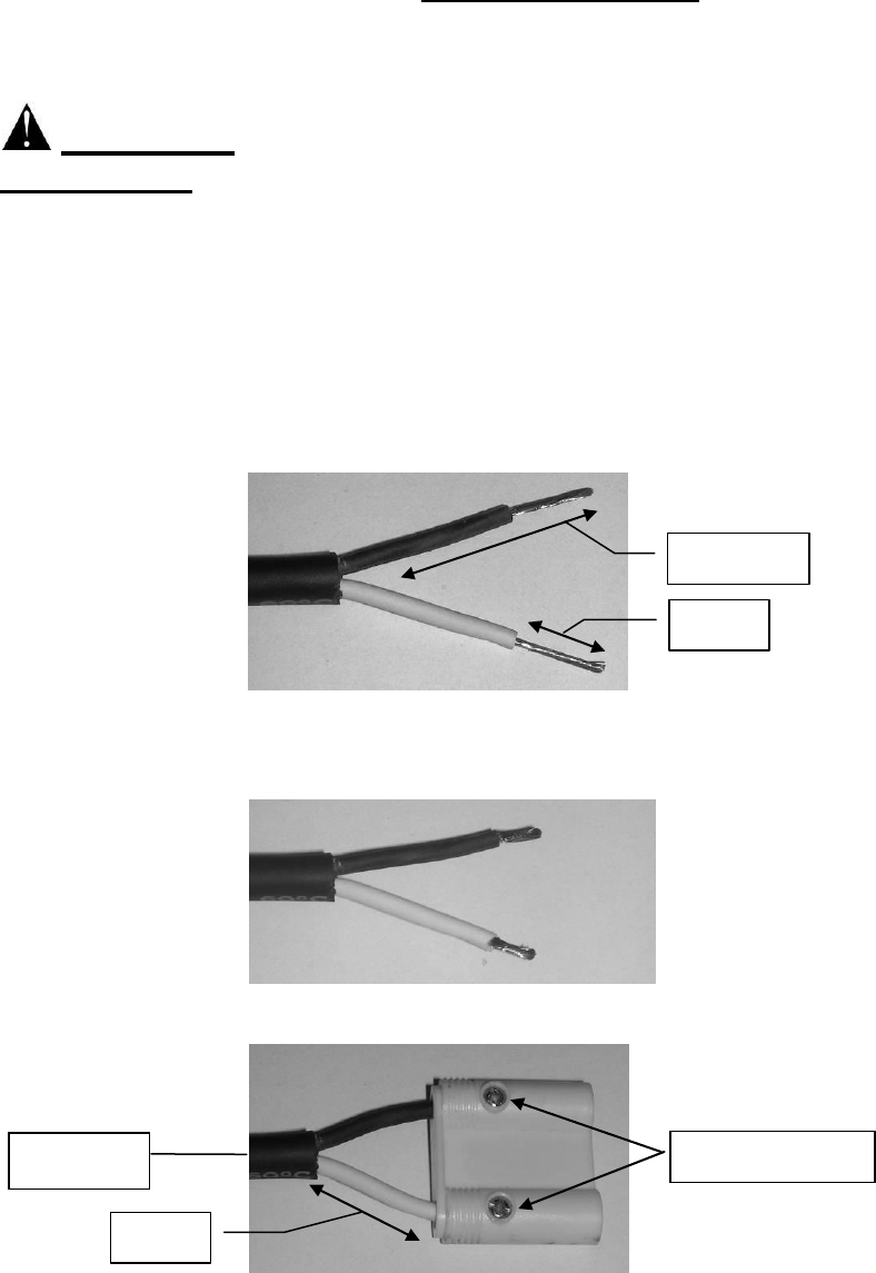
Attach Trap Connector (contents part D) to foot pedal release cable
WARNING: MAKE SURE THAT THE THROWING ARM IS IN THE
UNCOCKED POSITION, THE TRAP IS IN THE OFF POSITION AND THE
TRAP IS DISCONNECTED FROM THE BATTERY.
MAKE SURE THE TRAP FUNCTIONS CORRECTLY USING THE FOOT
PEDAL AND ANY ADJUSTMENTS TO THE TRAP ARE MADE BEFORE
INSTALLING ANY REMOTE RELEASE SYSTEM.
- Cut foot pedal release cable about 2 to 3 feet from body of trap
- From the cable coming from the trap, remove 1-1/2” of outer insulation from cable and
1/2” of insulation from each of the 2 signal wires as shown
- Fold over 1/4” of the bare signal wires back as shown
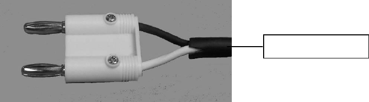
- Using a small screwdriver first fully loosen each of the lock screws in the trap
connector. Insert each of the signal wires into the connector so there is 3/4” of insulated
signal wire left out of the connector as shown. Tighten each of the lock screws fully so
they grip each wire.
1/2”
1-1/2”
3/4”
Lock screws
To trap
Machin
e
9
- If foot pedal is still needed, attach Foot Pedal Connector (see contents part E) to
remaining foot pedal release cable using the same procedure. The receiver can then be
unplugged and the foot pedal cable plugged back in so foot pedal can be used.
- Repeat procedures for other receivers and traps
Mounting receiver(s)
- Receiver(s) should be mounted above ground level and close to the 12V power source
with the receiver antenna pointed straight up.
- An ideal location is on the top of the 12V battery; use the included Velcro mounting
pads (contents part F).
- Do not mount the receiver to the trap machine, as vibration may damage internal
components.
To foot pedal

10
VII. Operation
To operate trap(s) follow the steps below:
1. Safe release trap, set trap main power switch to OFF and disconnect trap from 12V
battery
2. Plug receiver output connector into trap connector on release cable of trap
3. Connect trap to 12V battery
4. Connect receiver to 12V battery. Red clip connects to positive (+), Black clip connects
to negative (-). If the battery terminals are too big to connect the clips to, connect the
receiver power clips to the trap power clips (Green POWER light turns on)
5. Set trap main power switch to ON or RUN
6. Press ARM button on receiver (Red READY light turns on), Repeat for second trap if
needed.
7. Turn the remote transmitter ON/OFF MICROPHONE dial to the midpoint position
between MIN and MAX to set the initial microphone sensitivity.
8. Program trap release sequence using buttons on front of transmitter. See Pages 6, 12
and 13. In bright sunlight, shield the transmitter from the sun so the LED's can be seen
easier.
When the transmitter is set to AUTO mode:
- The microphone sensitivity will need to be adjusted so a loud voice call (PULL!,
BIRD!, etc) will activate the transmitter, but background noise and loading/re-
loading a shotgun will not activate the transmitter. Turn microphone dial clockwise
to increase sensitivity (softer sound will activate the transmitter) or
counterclockwise to decrease sensitivity (louder sound will activate the transmitter).
- In certain situations it may work best to disarm transmitter immediately after
shooting a target, and then rearming it when ready to shoot again.
- In windy conditions stretch the foam microphone
wind filter over the microphone to reduce the
sensitivity of the microphone to wind noise. The
filter can be permanently attached with a small
drop of adhesive.
11
9. Attach transmitter using belt/pocket clip. Preferred in-use transmitter placement for
right-handed shooters is on front left pants/shirt pocket or on belt opposite shooting side.
Left-handed shooters should place the transmitter on front right pants/shirt pocket or on
belt opposite shooting side. For optimum performance keep microphone clear of all
obstructions such as clothing.
10. Operate trap(s) by depressing RESET button on remote (when unit set to manual
mode) or making a loud call (PULL!, BIRD!, etc) (when unit set to auto mode) to launch
target from trap(s).
11. Receiver activation adjustment if needed. Remove bottom panel of receiver and use a
small screwdriver to adjust rotary dial.
If the throwing arm does not rotate far enough for a target to be thrown with a
release, press ARM button on receiver to disarm trap (Red READY light turns off) and
rotate the adjustment dial clockwise to a larger number.
If the throwing arm cycles more than once (launches two (2) or more targets) with
a single release, press ARM button on receiver to disarm trap (Red READY light turns
off) and rotate the adjustment dial counter clockwise to a smaller number.
To disarm the receiver(s) and safely stop trap(s) operation:
1. Turn the ON/OFF dial of the transmitter to the “OFF” position
2. Press ARM button on each receiver (Red READY light turns off)
3. Safe release each trap and set main power switch on trap to OFF
4. Disconnect each trap and receiver from 12V battery
12
VIII. Operational Examples
Shooting targets with a single trap
(Receiver programmed as A and connected to trap)
Turn on and ARM receiver connected to trap
Step 1 Turn on unit and set microphone
sensitivity to mid point
Step 2 Press T1 to set the desired time delay
(in seconds) for the first trap
Step 3 Press #T and set to 1
Step 4 Press SEQ and set to A-B to launch
targets from a trap connected to a receiver
programmed as A
Step 5 T2 has no function and will not
illuminate
Step 6 Press ARM to select Manual or Auto
release.
Step 7 Clip transmitter to front pants pocket,
shirt pocket, or belt.
Step 8 Press RESET button
If ARM set to Manual, Press RESET button to send release signal to receiver.
If ARM set to Auto, Press RESET button to arm unit and now a sound will activate unit
and send release signal to receiver. Press RESET button or any front button to
disarm transmitter.
1
2
3
4
5
6
8
13
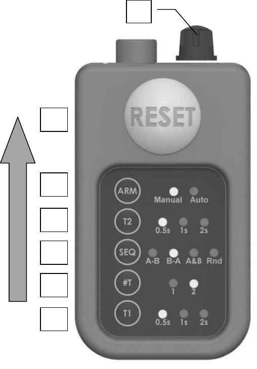
Shooting targets with 2 traps
(One trap connected to receiver programmed as A and the other trap
connected to receiver programmed as B)
Turn on and ARM receivers connected to traps
Step 1 Turn on unit and set sensitivity to mid
point
Step 2 Press T1 and set the desired time delay
(in seconds) for the first trap
Step 3 Press #T and set to 1 or 2 for number of
traps launching targets
Step 4 Press SEQ and set sequence of traps
If #T set to 1
A-B (receiver A will activate)
B-A (receiver B will activate)
Rnd (A or B will activate)
If #T set to 2
A-B (receiver A, then receiver B will
activate)
B-A (receiver B, then receiver A will
activate)
A&B (receivers A&B will activate
simultaneously)
Rnd (A-B, B-A or A&B will activate)
Step 5 Press T2 and set the desired time delay between the first trap and the second trap.
(If #T set to 1 or SEQ set to A&B, this setting disabled)
Step 6 Press ARM and set to Manual or Auto release
Step 7 Clip transmitter to front pants pocket, shirt pocket, or belt.
Step 8 Press RESET button
If ARM set to Manual, Press RESET button to send release signal to receiver.
If ARM set to Auto, Press RESET button to arm unit and now a sound will activate unit
and send release signal to receiver. Press RESET button or any front button to
disarm transmitter.
2
8
6
5
4
3
1

14
IX. Troubleshooting
WARNING: MAKE SURE THAT THE THROWING ARM IS IN THE
UNCOCKED POSITION, THE TRAP IS IN THE OFF POSITION AND THE
TRAP IS DISCONNECTED FROM THE BATTERY BEFORE MAKING
ANY ADJUSTMENTS TO RECEIVER OR TRAP.
The Trap Arm Rotates But Doesn’t Launch a Target
1. Rotate the adjustment dial located inside the receiver clockwise to a
larger number (see Page 11)
The Trap Launches More Than 1 Target
1. Rotate the adjustment dial located inside the receiver counter clockwise
to a smaller number (see Page 11)
The Transmitter Power Light is Rapidly Flashing
1. Replace the batteries in the transmitter
The Transmitter Does not Operate the Trap
1. Check that the red READY light on the receiver is on
2. Check that the armed light on the transmitter turns on when the reset
button is pushed in manual mode, or a sound command is received in
auto mode
3. Reprogram the receiver to the push button transmitter (see Section V)
4. Replace the batteries in the transmitter and check battery orientation
5. Check that the receiver is receiving a signal from the transmitter
- With the trap turned OFF, listen that the receive clicks when the
transmitter sends a signal.
6. Check the wiring from the receiver to the trap machine
Reduced Operating Range
1. Replace the batteries in the transmitter
2. Reposition the receiver unit

15
ORDERING PARTS
Parts can be ordered through the Onalaska Operation’s Customer Service Dept.
at (800) 635-7656.
Prices are subject to change without notification. Minimum order value of $10.00
PART NUMBER DESCRIPTION
60R176 Push Button Remote
60R177 Replacement / Additional Receiver
60R178 Trap Connector (see contents part D)
60R179 Foot Pedal / Receiver Connector (see contents part E)
60R186 Voice Operated Transmitter
60R187 Microphone Wind Filter

16
Warranty and Contact Information
LIMITED WARRANTY
Your new Champion® Wireless Voice Release System is warranted to be free from defects in
materials and workmanship for a period of one (1) year from the date of purchase. This warranty is
extended only to the original consumer purchaser. During the warranty period, we will replace any parts
that contain defects in materials or workmanship at our expense. You must keep your receipt as proof of
the date of purchase. If you have a warranty claim, contact our Customer Service Department at 1-800-
635-7656.
This warranty does not cover product or parts damaged or rendered defective due to accident, misuse,
abuse, modification, neglect, improper voltage, water damage, improper or unauthorized repair,
improper assembly, failure to follow operating instructions or damage due to normal wear and tear.
This limited warranty is your exclusive warranty. All other warranties are hereby expressly excluded
and disclaimed. ALL IMPLIED WARRANTIES, INCLUDING WITHOUT LIMITATION, ANY
IMPLIED WARRANTIES OF MERCHANTABILITY AND FITNESS FOR A PARTICULAR
PURPOSE ARE EXPRESSLY EXCLUDED AND DISCLAIMED. Some States do not allow
limitations on how long an implied warranty lasts, so the above limitation may not apply to you.
We will not be liable, in any event, for any amount in excess of the purchase price of the product. In no
event shall we be liable for any special, incidental or consequential damages of any kind arising out of
the purchase or use of this product. Some states do not allow the exclusion or limitation of incidental or
consequential damages, so the above limitation or exclusion may not apply to you. This warranty gives
you specific legal rights, and you may also have other rights which vary from State to State.
CONTACT US
Ammunition Accessories, Inc.
Champion Traps and Targets
Onalaska Operations
N5549 CTH Z
PO Box 39
Onalaska, WI 54650
Toll Free: (800) 635-7656
Internet: www.championtarget.com
Email: tech.expert@atk.com
MADE IN TAIWAN
PRINTED IN TAIWAN 10/4/2010