Sleep Number 5000B Universal Remote User Manual
Select Comfort Corp Universal Remote
user manual

ADJUSTABLE BASE
ASSEMBLY GUIDE
®
SLEEP NUMBER, SELECT COMFORT and the Double Arrow Design are registered trademarks of Select Comfort Corporation.
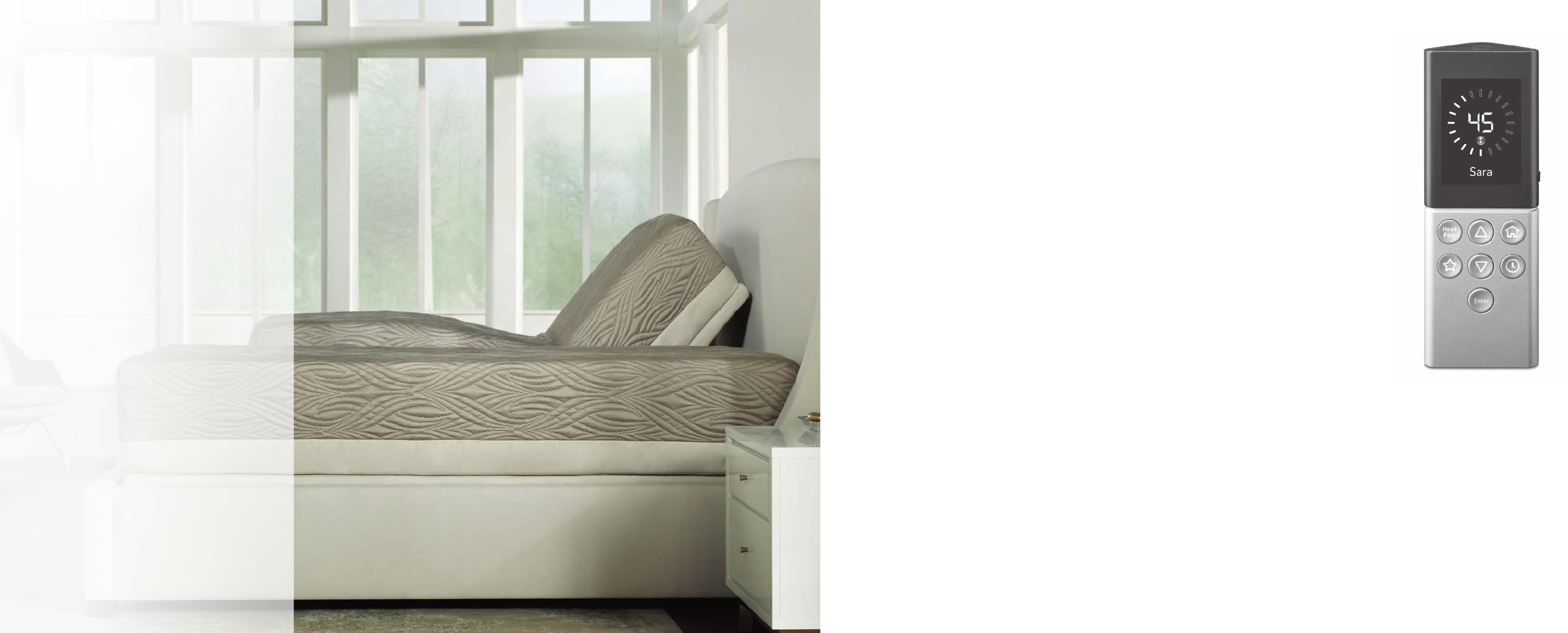
Congratulations
You’re about to take the personalized
comfort of your SLEEP NUMBER® bed to
the ultimate level. By adding an adjustable
base, you’re creating an even more
personalized sleep environment and
enhancing the customized comfort of the
bed that can significantly improve your
sleep quality.
At SLEEP NUMBER,
® we’re dedicated to
improving your sleep with new and
innovative products—everything from beds
to bedding solutions designed to help you
sleep just right. We know that you, too, will
fall in love with Sleep Number® comfort,
quality, and customer service—and a truly
individualized sleep experience.
What’s Inside
Congratulations! Your new SLEEP NUMBER® adjustable base is set up and ready to enjoy.
Inside, you’ll find instructions for the easy-to-use remote. Whether reading, relaxing or
sleeping soundly, we know you’ll fall in love with comfort you can adjust in every way.
Look to Sleep Number for innovations with your individual needs in mind.
Adjustable Base: What’s Included .........................................................pg XX
Your Adjustable Base at a Glance ..........................................................pg XX
Your Remote at a Glance .........................................................................pg XX
Preparing Your Adjustable Base Control™ System and Remote .........pg XX
Installing Your Mattress ............................................................................pg XX
Optional Accessories ...............................................................................pg XX
Assembling Your Headboard Brackets .................................................pg XX
Replacing Snap Latches ...........................................................................pg XX
Product Care .............................................................................................pg XX
Warranty ....................................................................................................pg XX
Advisory ....................................................................................................pg XX
Frequently Asked Questions ..................................................................pg XX
Welcome to Sleep Number InnerCircle® ...............................................pg XX
2 3

Twin Full/
Queen King
Split/
Flex Top
King
Remote 1112
Adjustable Base
Control™ System 1111
4-inch Leg 4488
Caster 4488
Mattress Retainer Kit 1122
Bed Strap Kit
King bases only 0011
Power Cord 1111
Under-bed Lights
FlexFit Plus™ only 1222
Adjustable Base: What’s Included
Assembling Your Adjustable Base
Carefully check the contents of your base boxes.
Make sure you have the correct number of components for the
size of bed you purchased. If you are missing any items listed to
the right, please call 1.800.472.7185 or email Customer Service at
customerservice@selectcomfort.com
Before You Begin
Remote Adjustable Base
Control™ System
4-inch Legs
Mattress Retainer Kit
Casters
Bed Strap Kit Power Cord Under-bed Lights
Assembling Your Base
Adjustable Base Components
FPO
FPO
May vary by model
King bases onlyFlexFit Plus™ only
May vary by model
54
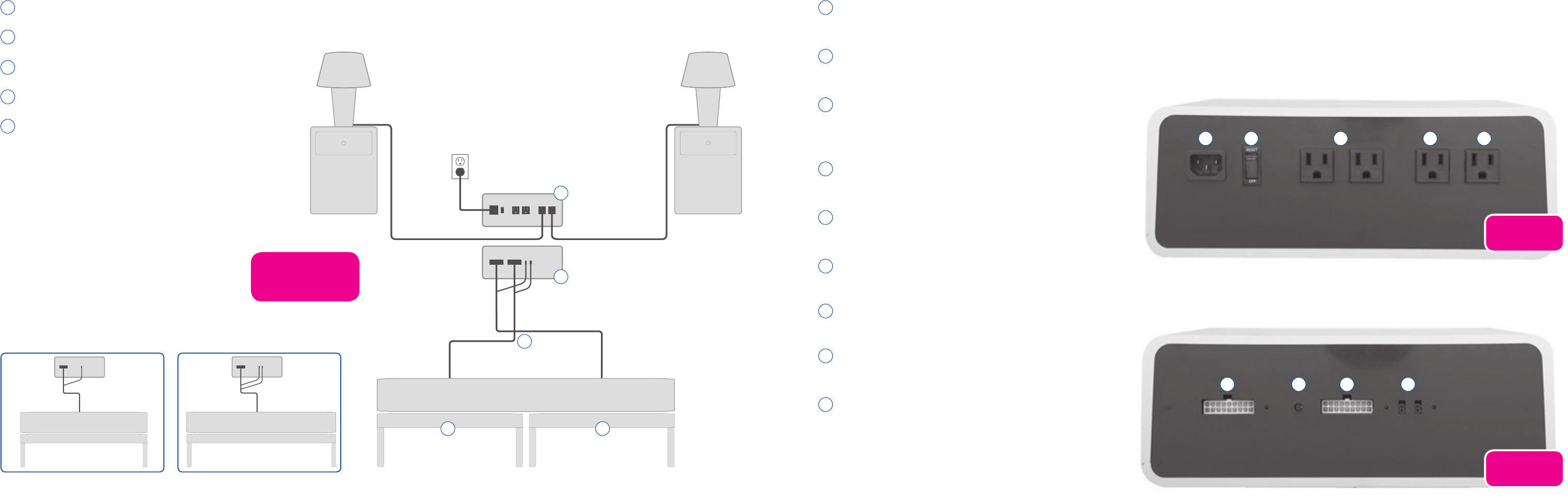
Adjustable Base Control™ System
FPO
Your Base at a Glance
Your Adjustable Base Control™ System at a Glance
A Left Adjustable Base
B Right Adjustable Base
C Junction Cables
D Adjustable Base Control™ System Back
E Adjustable Base Control™ System Front
A Power Cord Connector
Connect the AC power cord.
B Reset Button
Resets the Adjustable Base Control™ box.
C Outlets (FlexFit PLUS™ only)
Constant power for the Firmness Control™ system,
alarm clock, etc.
D Left Night Stand (FlexFit PLUS™ only)
Independent control of left nigh stand from remote.
E Right Night Stand (FlexFit PLUS™ only)
Independent control of left nigh stand from remote.
F Left Sleep Number®
Adjustable Base Connection (King Only)
G Right Sleep Number®
Adjustable Base Connection (King Only)
H Flat Base Button
Press to return base to flat position.
I Nightlight (FlexFit PLUS™ only)
Connection for under-bed lighting.
D
C
B A
E
Full/Queen Twin King
Mattress
MattressMattress
Foot of bed
A B C D E
F GH I
FPO
FPO
6 7
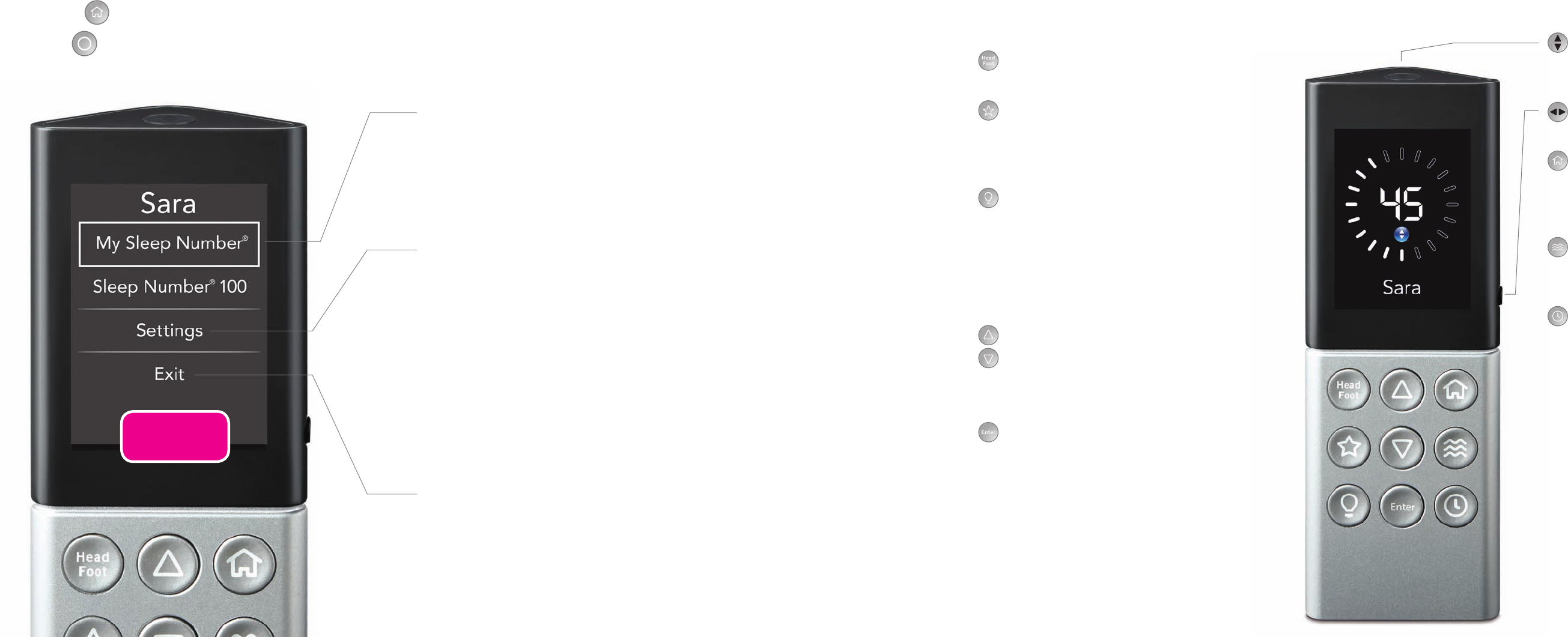
Your Remote at a Glance
Your Remote at a Glance
Press the Home button on your FlexFit™ or FlexFit PLUS™ remote to bring up the menu. For FlexTop™ bases, press the Menu/Select
button to bring up the menu. From here you can change your SLEEP NUMBER® setting, rename your side of the bed, find customer
support information and more.
Sleep Number®
• ReturntoyourfavoriteSleep Number setting at any time.
• AdjustSleep Number setting.
•Find Sleep Number® guides you to your ideal level of firmness,
comfort and support.
Bed Position
•Setorchangeyourbedposition,oradjusttheheadandfootpositionus-
ing the Up/Down buttons.
System
•Rename Side to name either side of the bed.
•Customer Support gives you contact information if you have
any questions.
•Changesettingandviewnotications
•Back returns you to the main menu.
Exit
• DisplaysthemostrecentSleep Number setting.
FPO
FlexFit PLUS™ Remote
My Sleep Number® Setting button
•Pressthisbuttontoreturntoyour
Sleep Number® setting
Side Button
•Presstochooseyoursideofthebed
Home
•SelectSleep Number,
®
Bed Position, Sleep IQ (when purchased),
and System
Massage
•
Choose type of massage or experience
a customized full body massage
Timer
•Settochangebedpositionandturnoff
massage and/or lights
Head/Foot
•
Press to select head or foot and use the
Up/Down buttons to adjust bed position
Favorite
•Choosepopularbedpositionsincluding
Read, Watch TV, and Zero Gravity
Lights
•Turnonorofflightsthatarepluggedinto
your FlexFit PLUS™ adjustable base
•Optionsincludeunder-bednightlight,
right nightstand, and left nightstand
•Brightenordimunder-bedlighting
in the System menu
Up/Down Buttons
•AdjustyourSLEEP NUMBER® setting or
your bed position. Scroll up or down in
any menu
Enter Button
•Presstoselectanoption
8 9
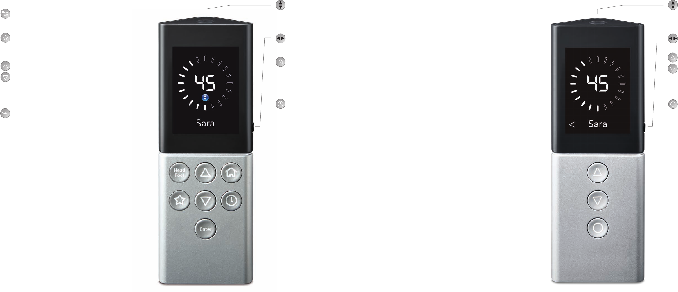
My Sleep Number® Setting button
•Pressthisbuttontoreturntoyour
Sleep Number® setting
Side Button
•Presstochooseyoursideofthebed
Home
•SelectSleep Number,
®
Bed Position, Sleep IQ (when purchased),
and System
Timer
•Settochangebedpositionandturnoff
massage and/or lights
Head/Foot
•
Press to select head or foot and use the
Up/Down buttons to adjust bed position
Favorite
•Choosepopularbedpositionsincluding
Read, Watch TV, and Zero Gravity
Up/Down Buttons
•AdjustyourSLEEP NUMBER® setting or
your bed position. Scroll up or down in
any menu
Enter Button
•Presstoselectanoption
FlexFit™ Remote FlexTop™ Remote
My Sleep Number® Setting button
•Pressthisbuttontoreturntoyour
Sleep Number® setting
Side Button
•Presstochooseyoursideofthebed
Up/Down Buttons
•AdjustyourSLEEP NUMBER® setting or
your bed position. Scroll up or down in
any menu
Menu/Select
•Letsyouselectyourfavorite
Sleep Number setting, bed position
and more
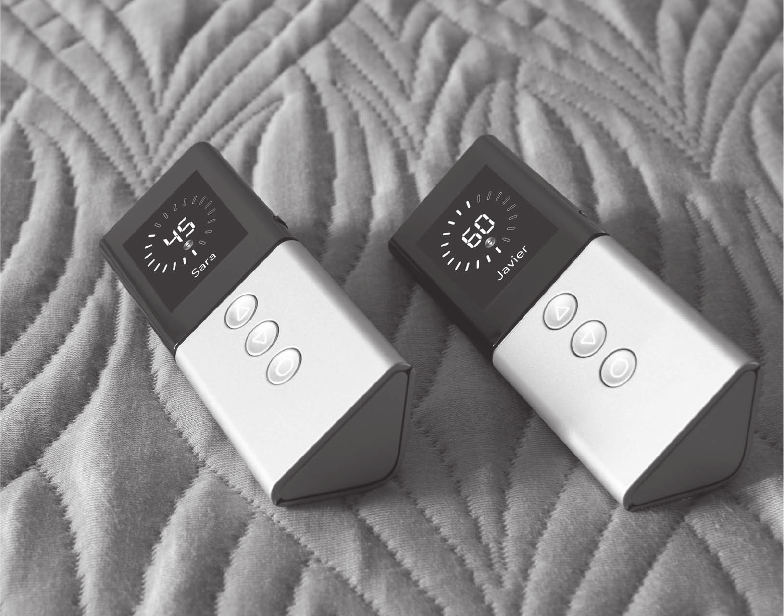
Individualizing Your Remote
10 11
Important Safety Instructions
When using an electrical furnishing, basic precautions should always be followed, including
the following:
DANGER – To reduce the risk of electric shock:
1. Always unplug this furnishing from the electrical outlet before cleaning.
WARNING – To reduce the risk of burns, fire, electric shock, or injury
to persons:
1. Unplug from outlet before putting on or taking off parts.
2. Close supervision is necessary when this furnishing is used by, or near children,
invalids, or disabled persons.
3. Use this furnishing only for its intended use as described in these instructions.
Do not use attachments not recommended by the manufacturer.
4. Never operate this furnishing if it has a damaged cord or plug, if it is not working
properly, if it has been dropped or damaged, or dropped into water. Return the
furnishing to a service center for examination and repair.
5. Keep the cord away from heated surfaces.
6. Never operate the furnishing with the air openings blocked. Keep the air openings
free of lint, hair, and the like.
7. Never drop or insert any object into any opening.
8. Do not use outdoors.
9. Do not operate where aerosol (spray) products are being used or where oxygen is
being administered.
10. To disconnect, turn all controls to the off position, then remove plug from outlet.
11. Contains Always On Receptacles. To Reduce Risk of Electric Shock – Disconnect power
strip from power source before servicing any equipment connected to the power strip.
12. Never place items on top of the control box.
13. For grounded products the following statement:
WARNING: Risk of Electric Shock – Connect this furnishing to a properly
grounded outlet only.
SAVE THESE INSTRUCTIONS.
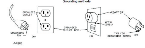
GROUNDING INSTRUCTIONS
(a) For all grounded, cord-connected products:
This product must be grounded. If it should malfunction or breakdown, grounding
provides a path of least resistance for electric current to reduce the risk of electric shock.
This product is equipped with a cord having an equipment-grounding conductor and a
grounding plug. The plug must be plugged into an appropriate outlet that is properly
installed and grounded in accordance with all local codes and ordinances.
DANGER – Improper connection of the equipment-grounding conductor can
result in a risk of electric shock. Check with a qualified electrician or serviceman if you
are in doubt as to whether the product is properly grounded. Do not modify the plug
provided with the product – if it will not fit the outlet, have a proper outlet installed by a
qualified electrician.
(b) For a grounded, cord-connected product rated less than 15 amperes and intended for
use on a nominal 120-volt supply circuit, the instructions in either 1) or 2)
1) This product is for use on a nominal 120-volt circuit, and has a grounding plug that
looks like the plug illustrated in sketch A (see Figure 63.1). A temporary adapter that
looks like the adapter illustrated in sketches B and C able to be used to connect this
plug to a 2-pole receptacle as shown in sketch B if a properly grounded outlet is not
available. The temporary adapter should be used only until a properly grounded
outlet (sketch A) can be installed by a qualified electrician. The green colored rigid
ear, lug, or the like extending from the adapter must be connected to a permanent
ground such as a properly grounded outlet box cover. Whenever the adapter is
used, it must be held in place by a metal screw.
2) This product is for use on a nominal 120-volt circuit and has a grounding plug
that looks like the plug illustrated in sketch A (see Figure 63.1). Make sure that the
product is connected to an outlet having the same configuration as the plug. No
adapter should be used with this product.
(c) For all other grounded, cord connected products: This product is for use on a circuit
having a nominal rating more than 120 volts (or this product is rated more than 15 amperes
and is for use on a circuit having a nominal rating of 120 volts) and is factory-equipped with
a specific electric cord and plug to permit connection to a proper electric circuit. Make
sure that the product is connected to an outlet having the same configuration as the plug.
No adapter should be used with this product. If the product must be reconnected for use
on a different type of electric circuit, the reconnection should be made by qualified service
personnel.
(d) For permanently connect products:
This product must be connected to a grounded metal, permanent wiring system, or an
equipment-grounding conductor must be run with the circuit conductors and connected
to the equipment-grounding terminal or lead on the product.
12 13
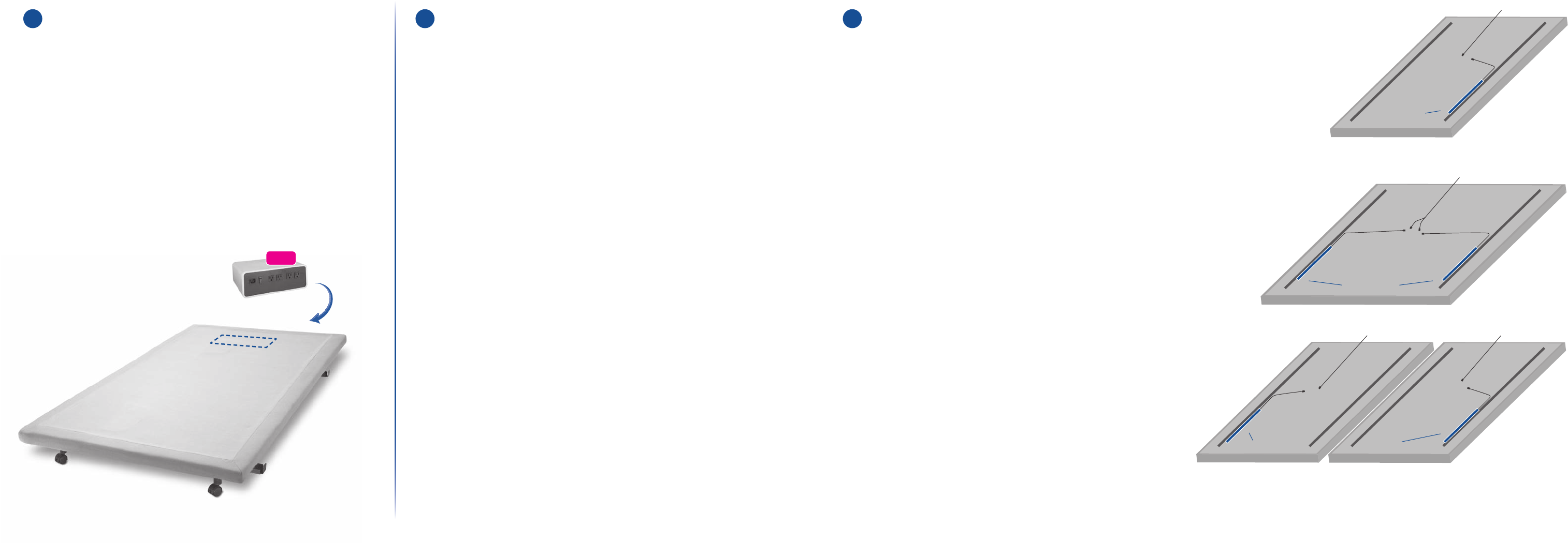
Control Box and Remote
Preparing Your Adjustable Base Control™ System &
Remote
1 Adjustable Base Control™
System Placement
•Place the Adjustable Base Control™ system on the
floor under the head of the bed.
•Plug the power cord into the Adjustable Base
Control™ system. Do NOT connect to power at this time.
•FlexFit PLUS™ only: Plug night stand lights (not included)
into corresponding “Left Night Stand” and “Right Night
Stand” outlets on the Adjustable Base Control system. See
diagram on page XX for outlet locations.
2a Connect Your Under-Bed Lighting
(FlexFit PLUS™ only)
•For Twin size beds, you will install one light; for Full,
Queen, and King size beds you’ll install two lights. See the
diagrams at right for under-bed light placement.
•Peel the adhesive backing off one LED light and install
the light on the vertical surface inside the rail under the
adjustable base, facing toward the center of the bed (see
diagram for location). For Full, Queen, and King beds,
install the second light on the second base with the light
facing toward the center of the bed (see diagram for
location). Ensure that each light faces toward the center
of the bed.
•Plug the LED connector(s) into junction cable(s) attached
to the underside of the adjustable base.
•Plug the junction cable connector(s) at the head of the
bed into the Adjustable Base Control™ system.
NOTE: Lights should face inward toward the center of the
bed to create a glow when illuminated. Brightness can be
adjusted with the remote. Lights installed facing outward
will create a floodlight effect.
2 Connect Your
Adjustable Base(s)
•Plug the junction cable(s) under the adjustable base(s) into
the Adjustable Base Control™ system.
NOTE: King size beds have a left and right junction cable.
Twin
Junction Cable
Junction Cable
Junction CableJunction Cable
Light Location
Light LocationLight Location
Light Location
Full/Queen
King
Bottom of base shown.
FPO
14 15
Installing Your Mattress
3
Pair Your Remote With Your
Firmness Control™ System
&
Adjustable Base Control™
System
•Insert (2) AA batteries (included) into the remote and press
any button on the remote to illuminate the screen.
•A setup screen will appear on the remote. Follow the
on-screen instructions to complete setup, and add
additional remotes.
NOTE: For beds without a Sleep Number® Firmness
Control™ system, select Skip on the Setup screen and
proceed to step 4.
4 Pairing Replacement Remotes
•Using your first remote, select System, then Settings, then
Add Remote.
•Follow the on-screen instructions to complete setup
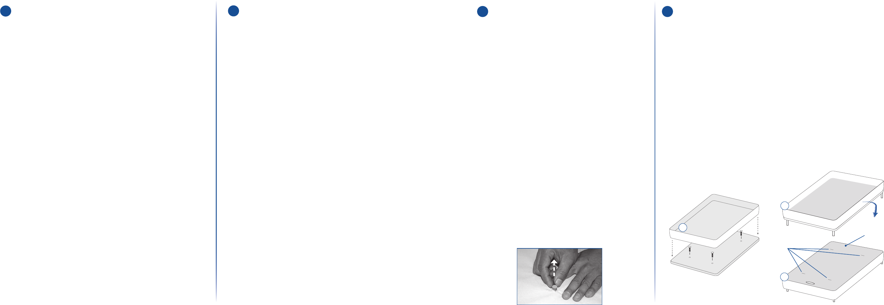
Installing Your Mattress
1 Prepare Your
Adjustable Base
Tools Required: utility knife, Phillips®
head screwdriver
WARNING: Exercise extreme caution
when using utility knife. The danger of serious
finger cuts is possible if utility knife is not
used correctly.
IMPORTANT: Wash hands before
beginning installation. Residue on hands
will easily transfer to cloth-covered bed
components.
•Verify adjustable base setup is complete.
•Identify four locator pins on the top of the
adjustable base. Locator pins mark the
threaded hole locations used for
SLEEP NUMBER® mattress attachment.
•Remove all four locator pins and Install (4) hex
head bolts.
2 Align Mattress
•Unzip the Sleep Number mattress cover and set cover top aside.
•Position the bottom of the Sleep Number mattress cover on top of
the adjustable base ensuring the head of the mattress cover (side with
openings for air hoses) is matched with the head of the adjustable base.
Make sure the air chambers and foam border walls are not installed,
leaving only the fabric mattress cover forming a box (diagram A below).
•Invert the mattress cover by pulling the sides of the mattress cover down
over the adjustable base (diagram B below).
• At each hex head bolt location, use the utility knife to make a small cut (no
larger than ¼” long) through the mattress cover fabric.
• Pull sides of mattress cover back up to their original position. Remove the
mattress cover.
Inverted
Mattress
Invert Sides
Cut Slits
Pull out each locator pin from the threaded lugs.
C
B
A
16 17
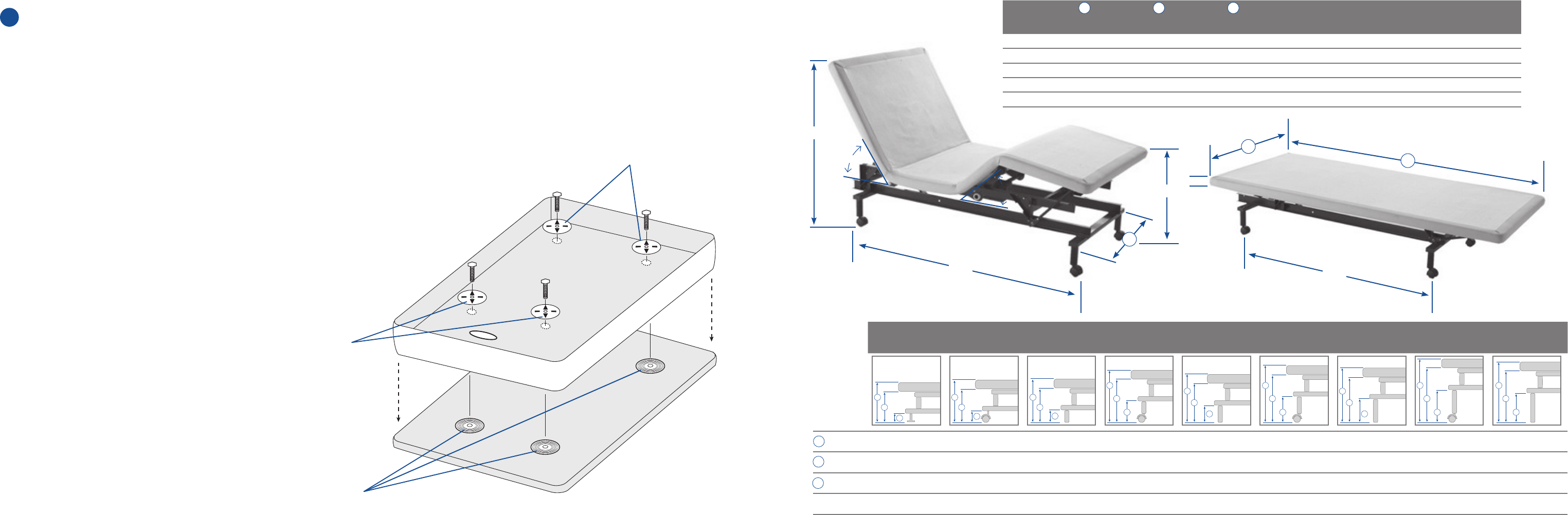
3 Install Mattress Retainer Kit
•Remove hex head bolts
•Place the bottom attachment pieces between the adjustable base
and mattress cover bottom at each hex head bolt location
• Place the mattress cover bottom back on the base. Align the
mattress cover with the adjustable base ensuring that the head of
the mattress is matched with the head of the base.
•Place the top attachment pieces over the four cuts and insert hex
head bolts.
•Tighten all four hex head bolts to finger tight. Do not over tighten.
•Complete mattress setup per the SLEEP NUMBER® mattress
installation instructions.
Top Attachment Pieces
Top Attachment Pieces
Bottom Attachment Pieces
Optional Accessories Size Chart
Optional Accessories Size Chart
Height to
Frame 1.5 - 1.9 2.5 4.1 6.6 7.125 9.6 9.1 11.6 11.1
Height to
Base 8.9 - 9.5 10.1 11.8 14.3 14.75 17.3 16.8 19.3 18.8
Height to
Mattress 10.9 - 11.5 12.1 13.8 16.3 16.75 19.3 18.8 21.3 20.8
Under-Bed
Clearance 0 0.5 2.5 5 6 8 8 10 10
Glide
Only
Threaded
Caster
Standard 4" Leg
(without caster)
Standard 4" Leg
(with caster)
Standard 7" Leg
(without caster)
Standard 7" Leg
(with caster)
Standard 9" Leg
(without caster)
Standard 9" Leg
(with caster)
Standard 11" Leg
(without caster)
39.625"
22"
61"
58°
44°
A
2"
56"
B
C
Bed Type Frame Width Base Width Base Length FlexTop™
Weight
FlexFit™
Weight
FlexFit Plus™
Weight
Twin Extra-Long 28" 37" 79.5" 110 lbs. 116 lbs. 138 lbs.
Full 38" 52.5" 73.5" 142 lbs. 147 lbs. 162 lbs.
Queen 38" 58.5" 79.5" 145 lbs. 150 lbs. 173 lbs.
Cal.King (per side)
28" 35.5" 83.5" 113 lbs. 118 lbs. 138 lbs.
King (per side) 28" 37" 79.5" 110 lbs. 116 lbs. 138 lbs.
A
D
B
E
C
F
DDDD D
D D D D
E E E
E E
E E E E
F F F
F F
F F F F
18 19

Code Qty.
Glides
(headboard bracket cannot be used with glides) 107397 4
Caster Cups 1164 49 4
Threaded Caster
7" Legs with Casters
9” Legs with Casters
11” Legs
TBD
107399
1164 47
1164 4 8
4
4
4
4
Swing Away Hinge Kit 107396 1
Adjustable Retainer Bar Kit 11745 0 1
FlexTop™ and FlexFit™
Headboard
Bracket Assembly
Full
Queen
Twin/E. King/Split King
Cal. King/Split Cal. King
118102
118103
118101
11810 4
1
FlexFit™ PLUS Headboard
Bracket Assembly
Full
Queen
Twin/E. King/Split King
Cal. King/Split Cal. King
11810 6
118107
118105
11810 8
1
Optional Accessories
The FlexTop,™ FlexFit™ and FlexFit PLUS™ adjustable bases
fit standard bedroom furniture. If your furniture does not
accommodate the adjustable base please contact
Customer Service at 1-800-472-7185 for potential solutions.
Call 1-800-580-7216 for accessory pricing and to order
the accessories listed in the chart to the right.
Swing Away Hinges (Split King Only)
For easy under-bed cleaning and bed-making access. Split King beds easily
split apart with the swing away hinges that attach between the headboard
and each side of the split king bed. Two hinges included.
Legs
For increased bed height and under-bed storage. Select from three leg
height options to replace the standard 4" legs. Four legs per set. See
diagram on page X for bed height dimensions.
Caster Cups
Required for use of adjustable bases on hardwood floors. Install under
caster wheels to prevent the bed from moving on hardwood flooring.
Four cups per set.
Adjustable Retainer Bar Kit
For use with non-SLEEP NUMBER® beds. Sleep Number beds use our
patented mattress-retaining kit to attach the mattress to the adjustable
base. The retainer bar is required when other mattresses are used with the
adjustable base to prevent the mattress from sliding when you raise the
head of the bed.
Glides
Our lowest bed-height option. Glides replace the standard 4” legs.
Four glides per set. See diagram on page X for bed height dimensions.
Note: headboard brackets cannot be used with glides.
Threaded Casters
Our second-lowest bed-height option. Threaded casters replace the
standard 4" legs. Four threaded casters per set. See diagram on page X for
bed height dimensions.
NOTE: headboard brackets cannot be used with threaded casters.
Optional Accessories
Glides
Adjustable Retainer
Bar Kit
Caster Cups Legs
Headboard Bracket
Assembly
Swing Away Hinge Kit
Threaded Casters
Optional Accessories
Optional Accessories
7" 9" 11 "
2120
Assembling Your Headboard Bracket
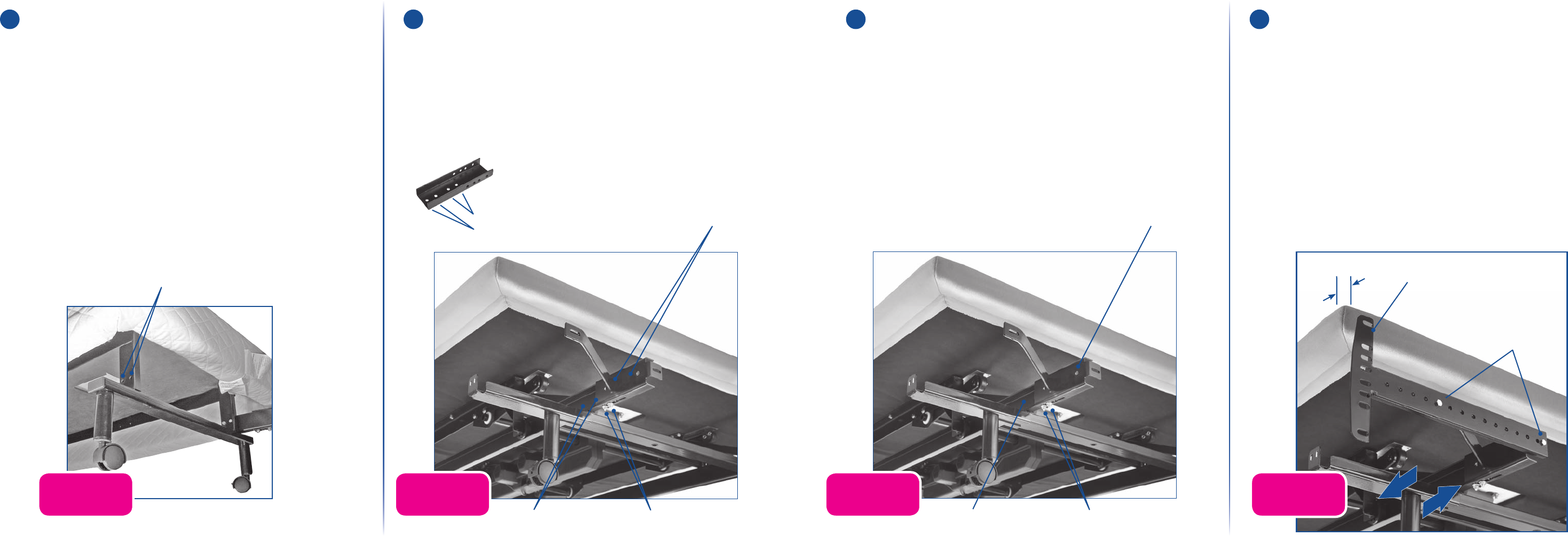
1 Install Headboard Brackets
•Headboard brackets are only needed for
non-freestanding headboards.
•Use remote to raise the head section of the bed to
access the adjustable base frame.
• Locate the headboard bracket assembly. On one side of
the adjustable base frame, locate two holes for channel
headboard bracket mounting.
2 Position Channel Connector
•For Full size beds, use inner mounting holes. For Queen,
King or California King beds, use outer mounting holes.
•Position channel connector so the flat side is flush against
adjustable base frame. Attach channel connector to
adjustable base frame using two 1½-inch hex head bolts/nuts.
Assembling Your Headboard Brackets (optional)
(2) Headboard Bracket Assembly
mounting holes
(2) 1½” Long
Hex Head Bolts
and Nuts
Queen, King & Cal King bed
mounting holes
Full size bed
mounting holes
Queen, King & Cal King bed mounting holes
Full size bed mounting holes
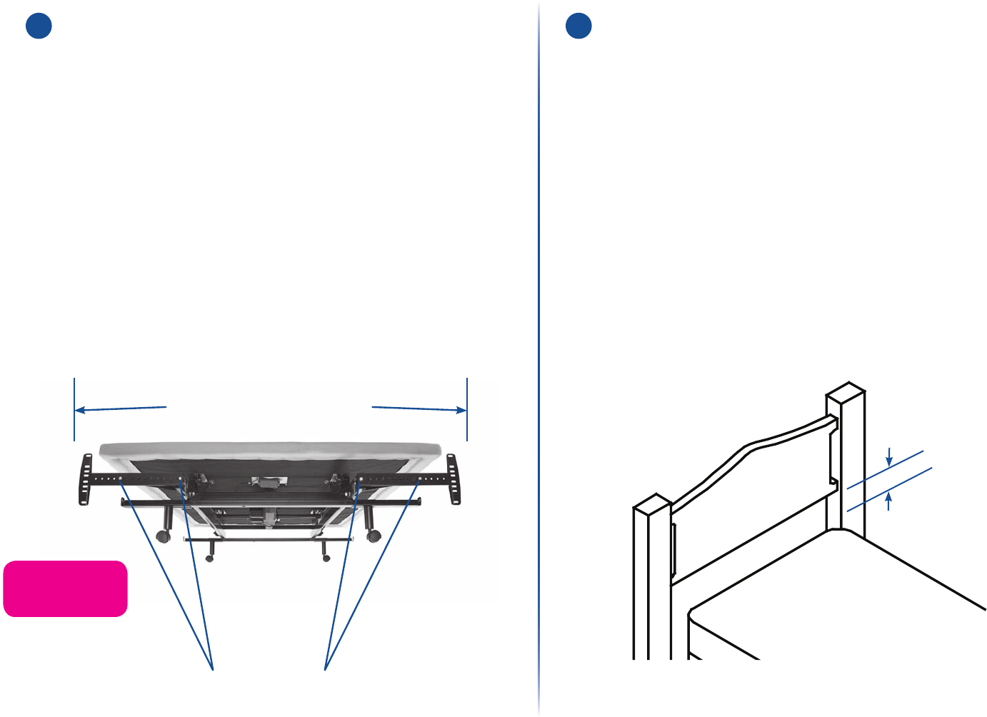
3 Attach Headboard
Bracket Channel
•Using two 3-inch carriage bolts/nuts, attach one headboard
bracket channel to the first channel connector.
•Hand tighten bolts/nuts (loosely) to allow adjustment of the
headboard bracket channels.
4 Attach Headboard
Bracket Flange
•Attach one headboard bracket flange to one of the bracket
channels with two 1-inch hex head bolts/nuts.
•Repeat on the other side to attach the second headboard
bracket flange.
•Slide headboard bracket assemblies (in or out) to achieve
a distance of 1½ inches (38.1 mm) to 2 inches (50.8 mm)
between the edge of the adjustable base and the
headboard bracket flange assemblies.
Full size bed
mounting holes
Channel
Connector
Bracket
Channel
(2) 1” Long
Hex Head Bolts
and Nuts
Headboard
Bracket Flange
1.5” to 2”
FPO FPO FPO FPO
22 23
Optional Accessories Size Chart
5 Adjust and Secure Brackets
•Firmly tighten the 3-inch carriage bolts on both
headboard bracket channels.
•Measure the distance (center-to-center) between the
mounting holes in the headboard.
•Measure the center-to-center distance between the
mounting slots of the headboard bracket flanges.
• If bracket flange adjustment is required to accept the
headboard, remove the 1-inch hex head bolts
and move flanges side-to-side to adjust. Reinstall bolts.
Tighten all headboard mounting bolts.
6 Install Headboard
•Securely install your headboard.
IMPORTANT SAFETY NOTICE:
The bottom of the headboard cross member must be
positioned so that there is no more than 3 inches (76.2mm)
between the headboard and the top of the mattress.
WARNING: Do not exceed 3 inches (76.2mm) in
order to avoid a person or pet being caught in the space
(referenced below) while the bed is in motion. Failure to
follow this instruction could result in serious personal injury
or death.
Remove 1-inch hex head bolts and relocate flanges to achieve
center-to-center distance required for headboard mounting holes
Measure flange slots center-to-center
to check headboard hole location
3” MAX.
Headboard cross member location must not exceed 3 inches
(76.2mm) from the top of the mattress.
FPO
24 25
Snap Latch Replacement
1 Raise Foot of the Bed
•Using your remote, fully raise the foot of your bed to allow
ample working space.
WARNING: Danger of Entrapment. To prevent
serious or fatal injuries from entrapment, do not allow a
person (adult or child) or pet to play under the bed or base
or with any remote controls.
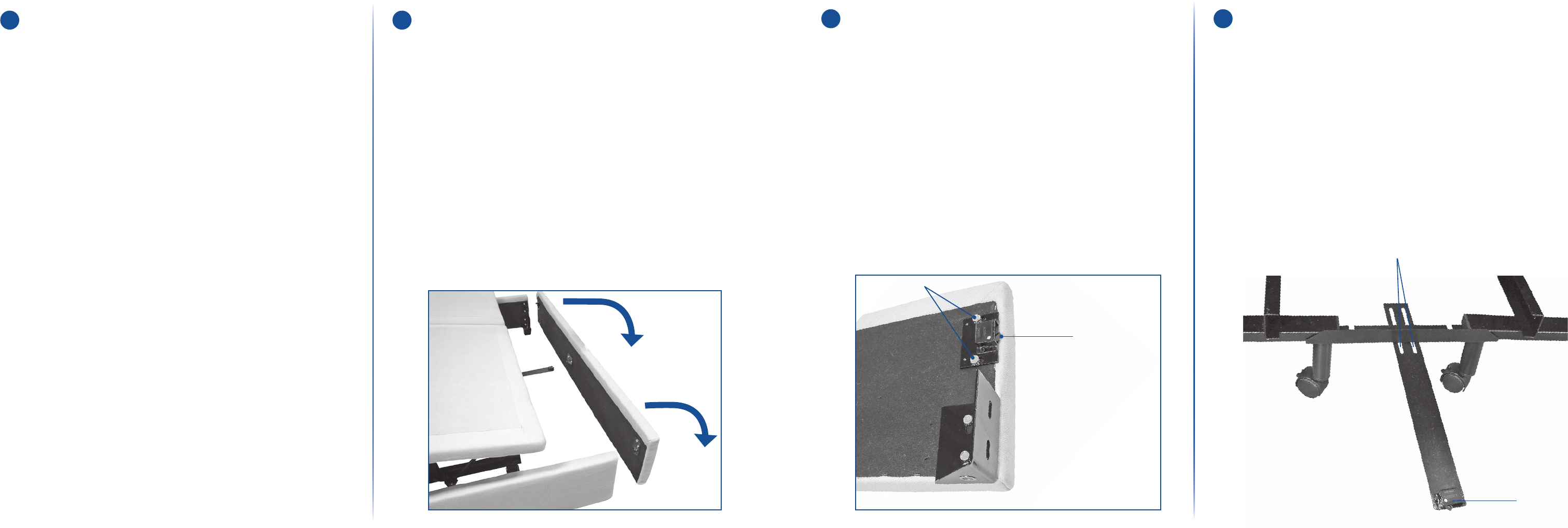
2 Remove Silhouette Footboard
•Remove the Silhouette footboard by pulling out from the
top of the footboard down toward the floor.
•Completely detach the footboard from the sideboards.
3 Remove Snap Latch(es)
•Using a 7/16 inch wrench, unscrew the two bolts
to remove the snap latch on the sideboard of the
Silhouette. Repeat for other side as needed.
4 King Bases Only
•After removing the snap latches from the sideboards,
remove the center snap latch, if necessary
Replacing Snap Latches on Beds with Base Silhouette (FlexFit™ & FlexFit Plus™ Only)
Snap Latch Bolts
Snap Latch
Snap Latch Bolts
Snap Latch
26 27
Snap Latch Replacement
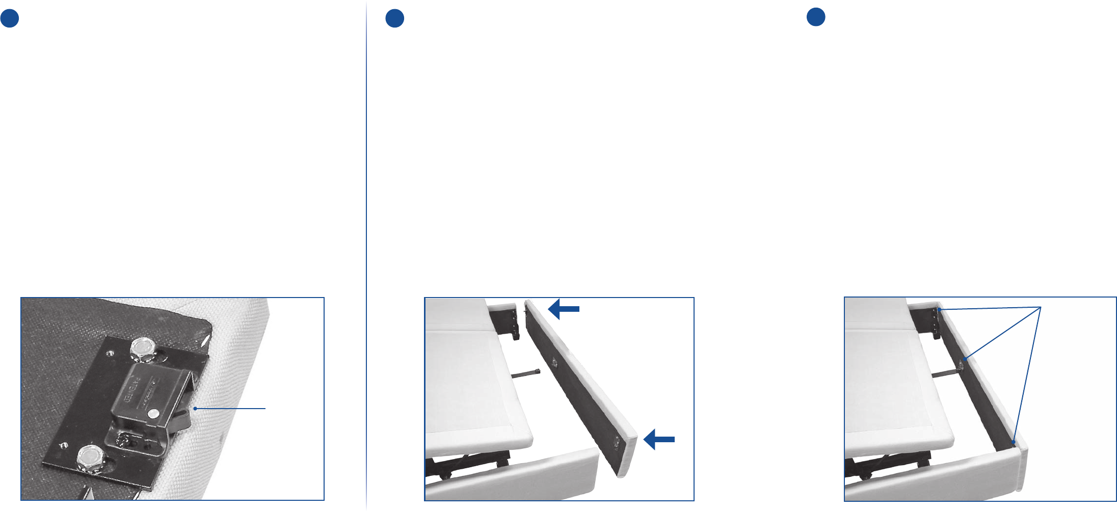
5 Attach New Snap Latch(es)
•After removing the snap latch(es) from the sideboards,
place the new snap latch(es) in the same areas and loosely
replace the bolts, allowing movement for alignment.
•For King size beds, replace the center snap latch,
if necessary. Loosely replace the bolts, allowing
movement for alignment.
6 Reconnect Footboard and
Align to Silhouette
•Reconnect the Silhouette footboard and align the
footboard to the Silhouette sideboards, eliminating
any gaps.
7 Tighten Bolts
•Once aligned, with Silhouette footboard attached,
use the wrench to tighten all bolts on snap latches.
Snap Latch
Snap Latch Bolts
28 29
Product Care
Cleaning Your Remote
• Wipe the body with a clean cloth dampened with a mild soap
and water solution.
• Wipe the display screen with a clean, dry, lint-free cloth.
CAUTION: Do not immerse in water or place in dishwasher.
Moving Your
Sleep Number® Bed
• Always disassemble the base. Bag all hardware so that it is
not lost.
• The mattress can be fully inflated, capped off and packaged
in a mattress box for moving.
• If you don’t have a mattress box, double-bag the cover and
foam to prevent stains. Deflate and box the air chamber(s) to
prevent possible damage.
• Pack the Firmness Control™ system in a box with packing
material. Transport with minimal exposure to shock
and vibration.
• Tuck the remote, air chamber caps and instructions in the
box with the Firmness Control™ system to prevent them from
being lost.
Moving Your Adjustable Base
• Copy to come
Product Care
30 31
Warranty
FlexFit™ Warranty Silhouette Warranty
2-5-25 Warranty
Leggett & Platt, Incorporated (“L&P”) warrants this adjustable base to the
consumer who is the original purchaser (the “purchaser”), subject to the terms and
conditions set forth herein. This warranty begins on the “warranty commencement
date” which is the date of purchase for new unused bases and the date of
manufacture for bases that have been used as floor or display models. Thus, on
a floor model base, the warranty is a portion of the limited 25 year warranty.
Full 2 Year Warranty
This adjustable base is warranted against defects in workmanship or materials for a
period of 2 years from the warranty commencement date. Upon notice during the first
2 years after the warranty commencement date, L&P will repair or replace (at no cost to
the purchaser) any defective adjustable base part, and L&P will pay all authorized labor
and shipping costs associated with the repair or replacement of any parts found to be
defective.
5 Year Limited Warranty
During the third through the fifth year from the warranty commencement date, upon
receipt of notice, L&P will replace any adjustable base part found to be defective. This
limited 5 year warranty shall not apply unless the defective part is returned to L&P within
10 days of purchaser’s receipt of the replacement part. Purchaser shall pay all service and
shipping costs related to the replacement of the defective part.
25 Year Limited Warranty
Upon notice during the sixth year through the twenty-fifth year from the warranty
commencement date, L&P will replace, upon terms and conditions set forth
in this paragraph, any mechanical base part found to be defective. Electronics, electrical
components, drive motors and massage motors are excluded. This limited 25 year
warranty shall not apply unless the defective part is returned to L&P within 10 days of
purchaser’s receipt of the replacement part. In years 6–25, purchaser shall pay all service
and shipping costs related to the replacement of the defective part.
Additional Terms and Conditions
This warranty does not apply; (a) to any damage caused by the purchaser; (b) if there
has been any repair or replacement of adjustable base parts by an unauthorized person;
(c) if the adjustable base has been mishandled (whether in transit or by other means),
subjected to physical or electrical abuse or misuse, or otherwise operated in any manner
inconsistent with the operation and maintenance procedures outlined in this document
and this warranty; (d) to damage to mattresses, fabric, cables, electrical cords or items
supplied by dealers. Contact the dealer for warranty information on these items; (e) if there
has been any modification of the adjustable base without prior written consent by L&P; (f)
to costs for unnecessary service calls, including costs for in-home service calls solely for the
purpose of educating the consumer about the adjustable base or finding an unsatisfactory
power connection; (g) if the recommended weight restriction is not followed (refer to
Advisory section on page 25), the warranty will be void.
Repairs to or replacement of an adjustable base or its components under the terms
of this limited warranty will apply to the original warranty period and will not serve
to extend such period.
The decision to repair or to replace defective parts under this warranty shall be made, or
cause to be made, by L&P at its option and in its sole discretion.
Repair or replacement shall be the sole remedy of the purchaser. There shall be no liability
on the part of L&P for any special, indirect, incidental, or consequential damages or for
any other damage, claim, or loss not expressly covered by the terms of this warranty.
This limited warranty does not include reimbursement for inconvenience, removal,
installation, setup time, loss of use, shipping, or any other costs or expenses. Leggett &
Platt or its service technicians shall not be responsible for moving furniture or any other
items not attached to the adjustable base in order to perform service on the adjustable
base.
It is the sole responsibility of the purchaser to provide adequate space and accessibility to
the adjustable base. In the event that the technician is unable to perform service due to
lack of accessibility, the service call will be billed to the purchaser and the service will have
to be rescheduled.
L&P makes no other warranty whatever, express or implied, and all implied
warranties of merchantability and fitness for a particular purpose are disclaimed
by L&P and excluded from this agreement. Some states do not allow the exclusion
or limitation of incidental or consequential damages, so the above limitation or
exclusion may not apply to every purchaser.
This warranty gives the purchaser specific legal rights, and the purchaser may also have
other rights, which may vary from state to state. This warranty is valid in all 50 states,
Puerto Rico, and Canada. For warranty or other questions please contact Select Comfort
Customer Service first.
CONTACT INFORMATION: Select Comfort, Customer Service Department, 9800 59th
Ave N, Minneapolis, MN 55442, 1-800-472-7185
Subject to the terms and conditions and for the period set forth herein,
Leggett & Platt, Incorporated (“L&P”) warrants to the original consumer
purchaser (the “Purchaser”) that this silhouette kit is free of defects in material or
workmanship caused by the manufacturer. This warranty begins on the date of the
original retail purchase (“Warranty Commencement Date”).
2 Year Limited Warranty
Upon proper notice received during the two years after the original retail purchase, L&P
will repair or replace (at no cost to the Purchaser) any silhouette kit found by L&P to have
a defect covered by this warranty, and L&P will pay the original purchaser all labor and
shipping costs authorized by L&P for repair or replacement of such part.
Additional Terms and Conditions
This warranty does not apply: (a) to any damage caused by the Purchaser or any person
other than the manufacturer of the silhouette kit; (b) if there has been any repair or
replacement of silhouette kit by an unauthorized person; (c) if the silhouette kit has been
mishandled (whether in transit or by other means), subjected to physical or other abuse or
misuse, or otherwise operated, used, or maintained in any manner inconsistent with the
operation and maintenance procedures outlined in this warranty or in any manufacturer
instructions; (d) to tears, flattening of nap, pilling, fading or shrinking; (e) when heavy
soiling or abuse is evident; and (f) to wear and tear, defined as the deterioration/damage
that naturally and inevitably occurs as a result of normal use, wear or aging.
TO THE EXTENT ALLOWED BY APPLICABLE LAW: (i) NEITHER THIS WARRANTY NOR
THE WARRANTIES, IF ANY, IMPLIED BY LAW, SHALL EXTEND TO ANY PERSON OTHER
THAN THE ORIGINAL PURCHASER; (ii) REPAIR OR REPLACEMENT AS PROVIDED
IN THIS WARRANTY SHALL BE THE SOLE REMEDY OF THE PURCHASER; AND (iii)
L&P DISCLAIMS, EXCLUDES, AND IN NO EVENT SHALL HAVE ANY LIABILITY FOR
ANY SPECIAL, INDIRECT, INCIDENTAL, OR CONSEQUENTIAL DAMAGES OR ANY
OTHER DAMAGE, CLAIM, OR LOSS NOT EXPRESSLY COVERED BY THE TERMS OF
THIS WARRANTY. Some states do not allow the exclusion or limitation of incidental or
consequential damages, so the above limitation or exclusion may not apply to every
purchaser.
This limited warranty does not include reimbursement for inconvenience, removal,
installation, setup time, loss of use, shipping, or any other costs or expenses. L&P or its
service technicians shall not be responsible for moving furniture or any other items in
order to perform service under this warranty.
L&P makes no other warranty whatever, express or implied, and all implied warranties,
including any warranties of merchantability or fitness for a particular purpose, are
disclaimed by L&P and excluded from this agreement to the extent permitted by
applicable law. Implied warranties, if any, which under applicable law cannot be
disclaimed or excluded, are hereby limited to the same warranty periods as the express
warranty herein, and are subject to the same terms, conditions, and limited remedies
stated in this warranty.
This warranty gives the Purchaser specific legal rights, and the Purchaser may also have
other rights, which may vary from state to state. This warranty is valid in the United States,
Puerto Rico, and Canada. Notices and claims under this warranty must be in writing and
submitted to:
Select Comfort
Customer Service Department
9800 59th Avenue North
Minneapolis, MN 55442
1-800-580-7216
32 33
Advisory
Important Information
Read the following information carefully before using this product. This adjustable base
has been quality-engineered with design features to optimize your comfort and safety
when operated properly.
Product Ratings
The bed lift motors are not designed for continuous use. Reliable operation and full
life expectancy will be realized as long as the lift motors do not operate any more than
5 minutes over a 30 minute period, or approximately 15% duty cycle. Note: Massage
equipped beds are not designed for continuous, extended massage operation.
Massage systems are rated for a maximum of 2 hours of use within any 6 hour period.
Any attempt to circumvent or exceed product ratings will shorten the life expectancy
of the product and may void the warranty. The recommended weight restrictions for
FlexFit™ adjustable bases are as follows: DC equipped - 600 lb (272 kg) all sizes. The bed
will structurally support the recommended weights distributed evenly across the head
and foot sections. This product is not designed to support or lift this amount in the head
or foot sections alone. NOTE: Exceeding the recommended weight restrictions could
damage the adjustable bed and void the warranty. For best performance, consumers
should enter and exit the adjustable bed with the bed in the flat (horizontal) position.
CAUTION: DO NOT SIT ON THE HEAD OR FOOT SECTIONS WHILE IN THE
RAISED POSITION.
Operating Information
•After bed assembly is complete, operate remote to ensure proper bed functions.
•Keep moving parts free of obstruction (including sheets, clothing, tubing, wiring, and
products using electric power cords) during bed operation.
•Distribute body weight evenly over bed surface. Do not place entire weight on raised
head or foot sections of the bed, including during repositioning and entering or
exiting bed.
FCC Compliance
This device complies with part 15 of the FCC Rules. Operation is subject to the following
two conditions: (1) This device may not cause harmful interference, and (2) this device
must accept any interference received, including interference that may cause
undesired operation.
Any attempt to make changes or modifications to the remote (e.g. an intentional radiator)
could void the user's authority to operate the remote according to FCC certification
(section 15.231).
Small Children/Pets Warning
CAUTION: Immediately dispose of packaging material as it can smother small
children and pets. To avoid injury, children or pets should not be allowed to play under or on
the bed. Children should not operate this bed without adult supervision.
Hospital Use Disclaimer
CAUTION: This base is designed for in-home use only. It is not approved for
hospital use and does not comply with hospital standards. Do not use this base with tent
type oxygen therapy equipment or near explosive gases.
Pacemaker Warning
CAUTION: If the massage feature is in use, this product produces a vibrating
sensation. It is possible that individuals with heart assist pacemakers may experience a
sensation similar to exercise. Consult physician for complete information.
Raising/Lowering Mechanisms
The raise/lower feature will emit a minimal humming sound during operation. This is
normal. During operation, the lift arm wheels make contact with the platform support of
the bed. This applies slight tension on the moving components and resonance is reduced
to a minimum level. If excessive noise or vibration is experienced, reverse the movement
action (up or down) of the base with the remote. This should realign the base’s activating
mechanisms to the proper operational position.
Service Requirements
NOTE: Service technicians are not responsible for moving furniture, removing headboards
and footboards or any items required to perform maintenance on the adjustable bed. In the
event the technician is unable to perform service due to lack of accessibility, the service call
will be billed to the purchaser and the service will have to be rescheduled.
Lubrication
This product is designed to be maintenance free. The lift motors are permanently
lubricated and sealed—no additional lubrication is required. Do not apply lubricant to lift
motor lead screws or any nylon nuts or the bed may inadvertently creep downward from the
elevated position.
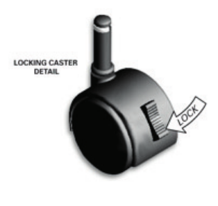
Locking Caster Safety Feature
This product is equipped with locking casters to prohibit the bed from movement. For best
results, place rubber caster cups under locking casters when the bed is located on smooth
or hard surface flooring. (It is possible for locking caster equipped beds to slide without
the use of rubber caster cups.) To activate locking casters, push down on the lock tab. To
disengage the locking mechanism, push up on the lock tab (see illustration below).
Massage Operation
The massage feature will emit a minimal tone during operation. This is normal. When the
massage level is increased, motor resonance will intensify accordingly.
Location Environment
The level of sound experienced during FlexFit™ operation is directly related to the location
environment. For example, when a bed is located on a hardwood floor with the massage
feature in operation, a vibrating tone will be audible. To minimize this resonance, place a
piece of carpet—or optional rubber caster cups—under each leg or caster of the bed.
See the Optional Accessories section on page XX of this manual for rubber caster cup order
information. It is possible to experience vibration or noise from the headboard brackets,
headboards or footboards if mounting bolts are not firmly tightened.
34 35

Base FAQ’s
Q.
What if I can’t get my support beams flush with the
side rails?
A. Make sure the letter on the support beam matches the letter
on the side rail. For example, the end of the support beam
labeled “A” should connect to the side rail labeled “A.”
Additional force may be required.
Q. How can I get my pins in all the way?
A. Slide pins into side rails in the direction of the arrow.
Make sure that the top of the pin is flush with the top of the
side rail.
Q. What can I do if I can’t get the deck panels to lie flat?
A. First, make sure all the pins and beams are flush. Then, set the
deck panel over the notches. You should then be able to slide
the panel inward into place.
Q. Where is the hardware for the footboard and headboard
brackets?
A. The same hardware for attaching the legs to the base is used
for attaching the brackets (sold separately).
Mattress FAQ’s
Q. Where are the air chamber caps? And where should
I store them?
A. The caps are in the Firmness Control™ system box. Please
store these in the mattress cover at the head of the bed in
case you should ever need to temporarily cap your
air chamber(s).
Q. What if my memory foam comfort layer appears to be too
small or irregular?
A. Gently shake the layer as you place it on your mattress and it
will recover its full size overnight.
Q. What if I feel like I’m rolling toward the edge or toward the
center of the mattress?
A. Although rare, these sensations could potentially be
experienced if one side of the mattress is set quite firm and the
other side quite soft. Call Customer Service at 1.800.472.7185
for a remedy to this situation if bothersome to you.
Q. What if I notice a rubber smell from the air chamber(s)?
A.
The odor you may smell is non-toxic and will fade over time.
To minimize the smell, unzip the mattress cover and allow the
air chamber to air out for a few hours. Laying a couple of dryer
sheets on top of the air chamber will also help mask any odor
by adding a fresh scent.
Q. Why are there body impressions on the mattress cover?
A. For a fuller look, use your Sleep Number® 100 function.
Body impressions in a normal innerspring mattress would
indicate that the spring support is compressing or breaking
down. The SLEEP NUMBER® bed features air, which we
believe is superior in every way for comfort and support.
Since air cannot break down, you receive the same support
after years of use as you do on the very first day.
Frequently Asked Questions
Frequently Asked Questions
FPO
Change from Troubleshooting,
John providing content?
FPO
Change from Troubleshooting,
John providing content?
36 37

Firmness Control™ System FAQ’s
Q. Why does my Sleep Number® setting change?
A. Your SLEEP NUMBER® setting is based on the combination of body
weight, volume of air in the air chamber and sleep position. Several
factors may contribute to fluctuations in your Sleep Number setting:
•TemperaturecancausechangesinyourSleep Number setting.
For example, a heated mattress pad will cause the Sleep Number
setting to increase.
•Barometricpressurerelatedtoweatherandaltitudecancause
your Sleep Number setting to change.
•WeightcanaffectyourSleep Number setting. The Firmness
Control™ system acts similarly to a scale. More weight means a
higher Sleep Number setting.
•DifferentsleeppositionscanaffectyourSleep Number setting.
The more concentrated the weight is, the greater chance the
Sleep Number setting will be higher (e.g., when you lie on your
side). When weight is distributed more evenly throughout the
chamber, it is more likely that the Sleep Number setting will be
lower (e.g., when you lie on your back or stomach).
Q. What do I do if the Firmness Control™ system doesn’t run?
A.
Make sure the power cord is securely plugged into the Firmness Control™
system and a surge protector. Verify that the power cord is plugged into
an outlet that has power and is not connected to a wall switch.
Q. I feel the mattress is losing air. What should I do?
A. Air loss can be caused by an unsecured hose connection, a defective air
chamber, or a defective Firmness Control™ system. First, make sure the
hoses and hose extensions are securely connected to the air chambers.
If you do not find any damaged or loose connections, identify which
of the following situations matches your situation and follow the
instructions for remedying your issue.
NOTE: To avoid variations in your Sleep Number setting or level of
comfort, make sure that you are lying in your preferred sleep position
when adjusting and checking your Sleep Number setting.
If you have a dual air chamber bed and suspect only one (1) side of
your SLEEP NUMBER® bed is getting softer:
•Inspecttheo-ringandconnectorsforcrackingordamage.
•Switchthehosesontheairchamberssothelefthose(markedwith
a white band) is attached to the right air chamber and the right
hose (marked with a blue band) is attached to the left air chamber.
You should hear a click when the hose is securely connected to the
air chamber.
•FilltheairchamberstotheappropriateSleep Number setting(s)
for the person sleeping on each side of the bed.
•Sleeponthebedandmonitorthefeelofthebed’srmnesson
both sides.
•Ifneitherchamberfeelssofterovertime,youmayhavehada
loose connection that was fixed when the hoses were switched.
Switch the hoses back to their correct positions and continue to
use the bed as usual.
•Ifanairchamberfeelssofterafterswitchinghoses,contactCustomer
Service with the results (the issue stayed on the same side of the bed
or it moved to the other side after switching hoses).
If you have a dual air chamber bed and both (2) air chambers are
getting softer or you have a single air chamber bed and feel the air
chamber getting softer:
Remote Control FAQ’s
Q. How do I capitalize a letter in the middle of my name?
A.
Select the letter and press the Up/Down buttons
simultaneously.
Q. How many characters can I use for my name?
A. Up to 11.
Q. My remote says there’s an inflation/connectivity error. What should
I do?
A. An error message lets you know an issue has been detected,
along with prompts for how to fix it. If the error is still not resolved,
you will be instructed to visit sleepnumber.com/chat or to call us
at 1.800.511.0054.
Q. How do I restore the remote’s original settings?
A. To erase all stored information, press the home button ,
select System, select Setting, select Reset Preferences, select
Factory Reset and follow the instructions on the remote.
Q Why won’t my remote turn on?
A. You may need to replace or check the orientation of the batteries.
Your remote comes with two AA batteries that should last about
six months with normal use. If new batteries don’t resolve the issue,
please visit sleepnumber.com/chat or call us at 1.800.472.7185.
Q. Why don’t I see Sleep IQ™ in my menu screen?
A. You need to have purchased the Sleep IQ™ system to have access
to the Sleep IQ™ data on the remote.
Q. How do I save my Sleep Number® setting?
A. Press the side button to choose your side of the bed. Press the
Up/Down buttons
to choose your Sleep Number setting, then
press the My Sleep Number® setting button on top of your remote
for the two seconds to save.
Q. How do I save my customized bed positions?
A. Adjust the bed position to your preference and hold the Favorite
button for 2 seconds to save over the bed positions. If you
wish to reset the bed positions back to the original position setting,
press the Home button , select System, select Settings, select
Reset Preferences, select Bed Positions and follow the instructions
on the remote.
Q. How do I reset my timer?
A. Press the Timer button and choose from the menu to adjust
the timers that are set. Scroll to select a new time option or select
Timer Off.
Q. How do I dim my under-bed nightlight?
A. Press the Home button , then select System, select Settings,
select Reset Preferences, select Nightlight, then press the Up or
Down
button to adjust to your brightness preference.
Q. How do I turn my nightstand lights on or off with the remote?
A. Press the Light button , then select the lights you want on or
off and press Enter . A lightbulb icon will appear when the light
selected is on and will disappear when the light is turned off.
Q. How do I change the name on my remote?
A. Press Home , then select System, select Settings, select Reset
Preferences, select Rename Side and follow the directions on the
remote to enter a new name.
Frequently Asked Questions
FPO
Change from Troubleshooting,
John providing content?
38 39

41
Congratulations on the purchase of your SLEEP NUMBER® bed. As a Sleep Number bed owner you are now
an Insider, a member of our InnerCircle.
SM Soon you’ll be enjoying all the benefits of a better night’s sleep on
your new Sleep Number bed.
Welcome to Sleep Number InnerCircle®
Go to sleepnumber.com/innercircle
Simply register your bed to start receiving exclusive discounts. Plus, you’ll get access to pass-along coupons
to share with friends and family, and everyone you know who could use a better night’s sleep.
Receive special savings.
You’ll always get 10% off every purchase. And, throughout the year, we’ll send you additional Insider-exclusive
offers on beds and bedding.
Earn rewards.
Improve the lives of friends and family by sharing what you love about your Sleep Number bed. Enjoy an exclusive
Insiders reward of $100 for referrals ONE through NINE who purchase a bed. When your 10th referral purchases,
you will receive another $699 for a total of $1,599 in rewards.
Be the first to know.
As an Insider, you’ll be the first to know about our latest innovations, from new Sleep Number beds to
bedding solutions that will improve your sleep.
Register Today for Insiders-Only Benefits
40

©2013 Select Comfort 7/13
If you ever have questions or need help finding your ideal comfort,
please visit us
at sleepnumber.com/chat to chat with a live representative 7 a.m. – 11 p.m.
(Central Standard Time) daily or call 1.800.472.7185
Representatives are available by phone
(Central Standard Time):
Monday-Friday 8 a.m. – 8 p.m.
Saturday 8:30 a.m. – 5 p.m.
Sunday Closed
Help is just a click or phone call away.
9800 59th Avenue North, Minneapolis, MN 55442
FPO
Need New