Smart Technologies and Investment SMARTST-1601 PUSH BUTTON User Manual ST 1601 Manual
Smart Technologies & Investment Ltd PUSH BUTTON ST 1601 Manual
Users Manual

Model ST-1601
Wireless push button
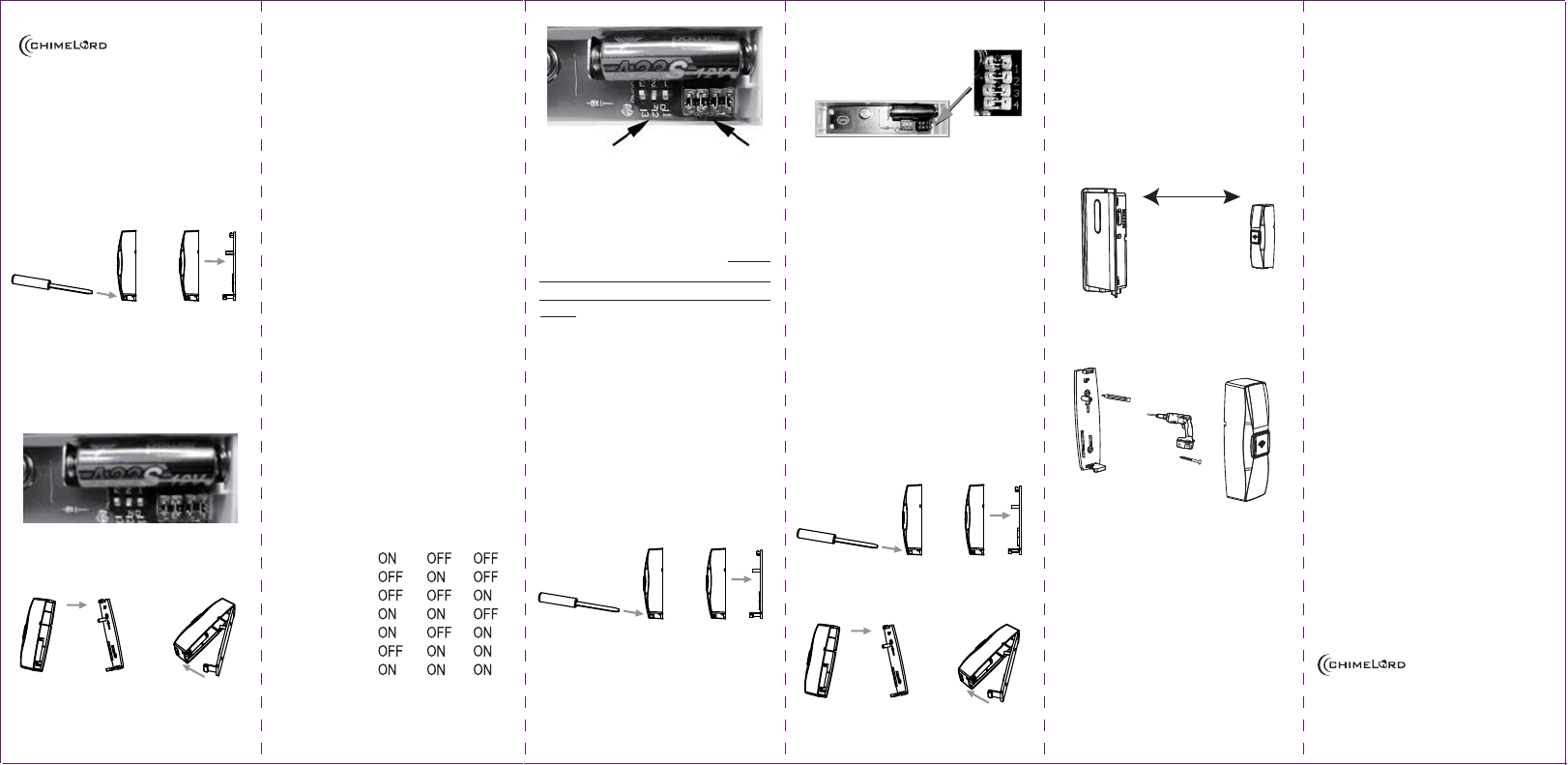
To install or replace the battery in the
wireless push button.
1. Remove the back cover of the push
button.
2.
Install the A23 (12 volt) battery with the
negative side of the battery (-) toward
the spring and the positive side of the
battery (+) toward the positive battery
holder as shown below.
3. Replace back cover as shown below.
Chime Tune Setting
All wireless chimes may have more than
one push button. The chime tune for each
push button is set with dip switches
numbered 1-3.
Single Push Button Kit: If you purchased
a kit with a single push button, the chime
tune will be set to Ding Dong from the
factory.
Dual Push Button Kit: If you purchased
a kit with two push buttons, one push
button will be set to Ding Dong and the
other push button will be set to Westmin-
ster from the factory.
The following instructions explain how to
change the tune on any wireless push
button.
1.
Remove the battery from the push
button transmitter.
2.
Locate the 3 dip switches shown below.
3.
Select the desired chime sound from
the table below.
Chime Sound Table
Position 1 2 3
Westminster
Ding Dong
Knock
Bronze Chime
Cuckoo Clock
Foghorn
Gong
ON: Switch On
OFF: Switch Off
Chime Dip Switchers House Code Jumpers
Pushbutton Dip Switches and Jumpers
Setting The House Security Code Setting
Each chime component has 4 jumpers for
setting the house security code. In most
cases you will not need to change the
factory settings for the house security
code. If your chime activates intermit-
tently or does not work at all, you may be
able to solve the problem by changing
your security code.
The chime and pushbutton must be set to
the same house security code for the
combination to operate together.
1.
Remove power or batteries from the
chime.
2.
To remove the batteries from the
pushbutton, open the pushbutton case
as shown below.
3. Locate the House Security Code door
and screw located on the back of the
Chime. Remove the screw and take
off the door.
4.
Locate the chime and pushbutton
jumpers shown below.
House Security Code Jumpers
5.
To change the house code, add, or
remove jumpers as needed. It is
recommended to change only one
jumper at a time and then test the
system for proper operation. The
jumpers on the chime and pushbutton
must match exactly.
Push Button Mounting Instructions
Note: Avoid mounting on metal surfaces,
a
s it may result in a reduced range of
transmission. Do not mount in an area
where exposed to direct rain.
a. Removing the back cover
b. Replacing the back cover
1. Push buttons are typically mounted at
the same height as the door knob or
handle (between 36" and 44" above
the floor).
2.
Before mounting, choose a mounting
location that is not farther than 45
meters
from the chime unit location.
No further than 45 meters
3.
Use back cover of push button as a
template to mark two screw holes.
4.
Drill two holes with 1/16” drill in marked
locations.
5.
Secure back cover to the mounting
surface with the 3x20mm screws.
6. Install the battery supplied with the kit,
observing proper polarity.
7. Press front housing onto back cover.
8.
Test Operations, if chime does not
work, see TROUBLESHOOTING.
Operation
Troubleshooting
Chime doesn't work:
1.
Make sure push button switch is
depressed and held for at least 1 second.
2. Make sure plastic tag is removed from
battery.
3.
Make sure house code switches 1-4 on
chime and push button match exactly.
4.
Verify battery orientation in push button.
5. Try fresh batteries.
6.
Make sure chime is not farther than
45 meters away from push button.
7. Ensure push button is not mounted on
metal, near metal studs, or near the
floor.
8. Try a new location for the chime.
Functional range may be adversely
affected by one or more of the following
factors: weather, radio frequency
interference, low transmitter battery and
obstructions between the transmitter and
receiver.
Made in China
is a trademark of Smart
Technologies & Investment Ltd.
www.chimelord.com
1
2
1
2
1
2
1
2
1
2
3
4
5
6
FCC WARNING
This device complies with Part 15 of the FCC Rules. Operation is
subject to the following two conditions:
(1) this device may not cause harmful interference, and
(2) this device must accept any interference received, including interference that may cause
undesired operation.
NOTE: The manufacturer is not responsible for and radio or TV interference caused by
unauthorized modifications to this equipment. Such modifications could void the user’s authority
to operate the equipment.