Smart Technologies and Investment SMARTWS101 Smart Panel User Manual WS 100S IB 080827 ai
Smart Technologies & Investment Ltd Smart Panel WS 100S IB 080827 ai
Users Manual
1
User Guide
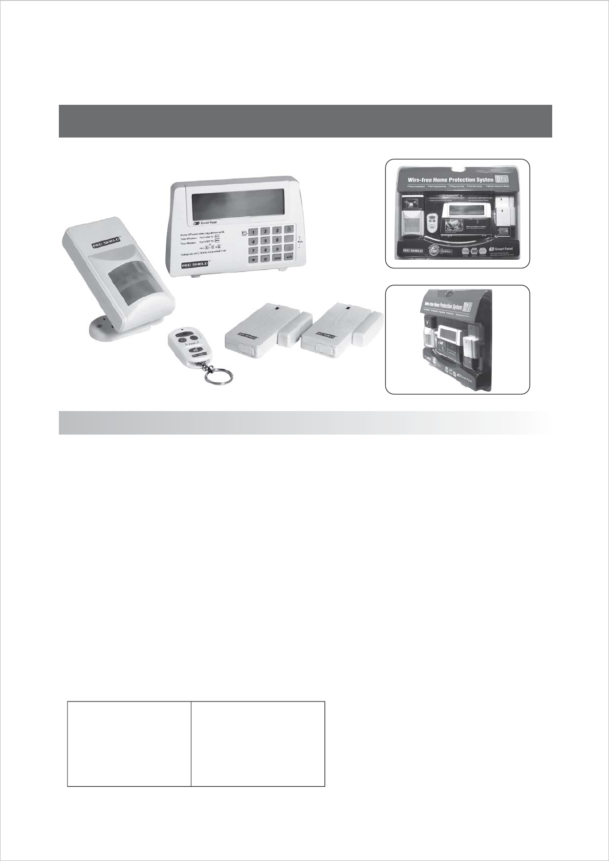
Wire-Free Home Protection System WS100S
Contents
Section 1 – Getting Started
1.1 Introduction to the System
1.2 Items included with the System
1.3 Introduction to the Smart Panel WS101
1.4 Introduction to the Smart Panel Backlight
Section 2 – Installing the Wire-Free Home Protection
System WS100S
2.1 Installing the Smart Panel WS101
2.2 Powering up the Smart Panel WS101
2.3 Understanding the Battery and AC Adaptor Symbols
Section 3 – Using the Wire-Free Home Protection
System WS100S
3.1 Program your 4-Digit PIN
3.2 Transmitting the Alarm Signal without a Siren
3.3 Operating different Modes
Section 4 – Installing the Sensors
4.1 Introduction to the Sensors
4.2 Installing the Sensors
4.3 Powering up the Sensors
4.4 Installing the Code Connectors
Section 5 -- Troubleshooting
5.1 FQA
5.2. Troubleshooting
5.3 Alarm System Limitations
Section 6 – General Information
6.1 Product Information
6.2 Specifications
6.2.1 Smart Panel WS101
6.2.2 4-Button Key Fob Remote WS101TX
6.2.3 Door/Window Magnetic Sensor WS102
6.2.4 Motion Sensor WS103
3.3.3 ALERT Mode
A. Entering the Alert Mode
B. Triggers in Alert Mode
3.3.4 HOME Mode
A. Entering the Home Mode
B. Triggers in Home Mode
3.3.1 STANDBY Mode
3.3.2 ARM Mode
A. Arming the System
B. Disarming the System
C. Zone Settings
D. Triggers in ARM Mode
2
Section 1 – Getting Started
1.1 Introduction to the System
The Wire-free Home Protection System WS100S is a high quality security system combined with user-friendly features that
allow you to know the state of security of your home at all times. The System is managed by a Smart Panel, which gathers
information from wireless sensors placed inside and at the entry points of your home. If the Smart Panel detects a security
breach, you will be alerted via indicator lights and sounds. For installation and proper use of the Smart Panel, please
familiarize yourself with this User Guide.
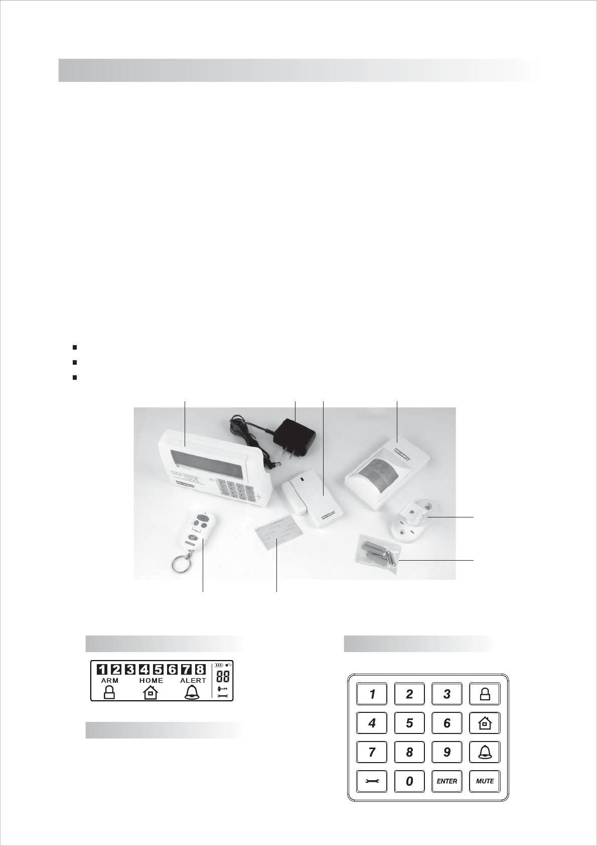
1.2 Items included with the System
Please check that all of the following items were included in the package before installing the System:
A. Smart Panel WS101
B. 4-Button Key Fob Remote WS101TX
C. Door/Window Magnetic Sensor WS102 (2 parts)
D. Motion Sensor WS103
E. AC Adaptor for Smart Panel
F. Velcro Sticker for Door/Window Magnetic sensor
G. Screws & Screw Jackets (3 sets)
H. Mounting Bracket for Detect Motion Sensor
Mounting Template
Quick Start Guide
User Guide
AECD
H
G
BF
1.3 Introduction to the Smart Panel WS101
LCD Screen: Keypad:
Numeric Buttons:
0,1,2,3,4,5,6,7,8,9
3
“9VDC INPUT” port
Siren
Battery Compartment:
For AC Adaptor (Included)
120dB Buzzer
Backup battery - 9V Alkaline Battery (Not Included)
House code - Pin Header x 4, Jumper: x 4
“Reset” button - When you lost the 4-Digit, press: “Reset” and enter factory
default password
1.4 Introduction to the Smart Panel Backlight
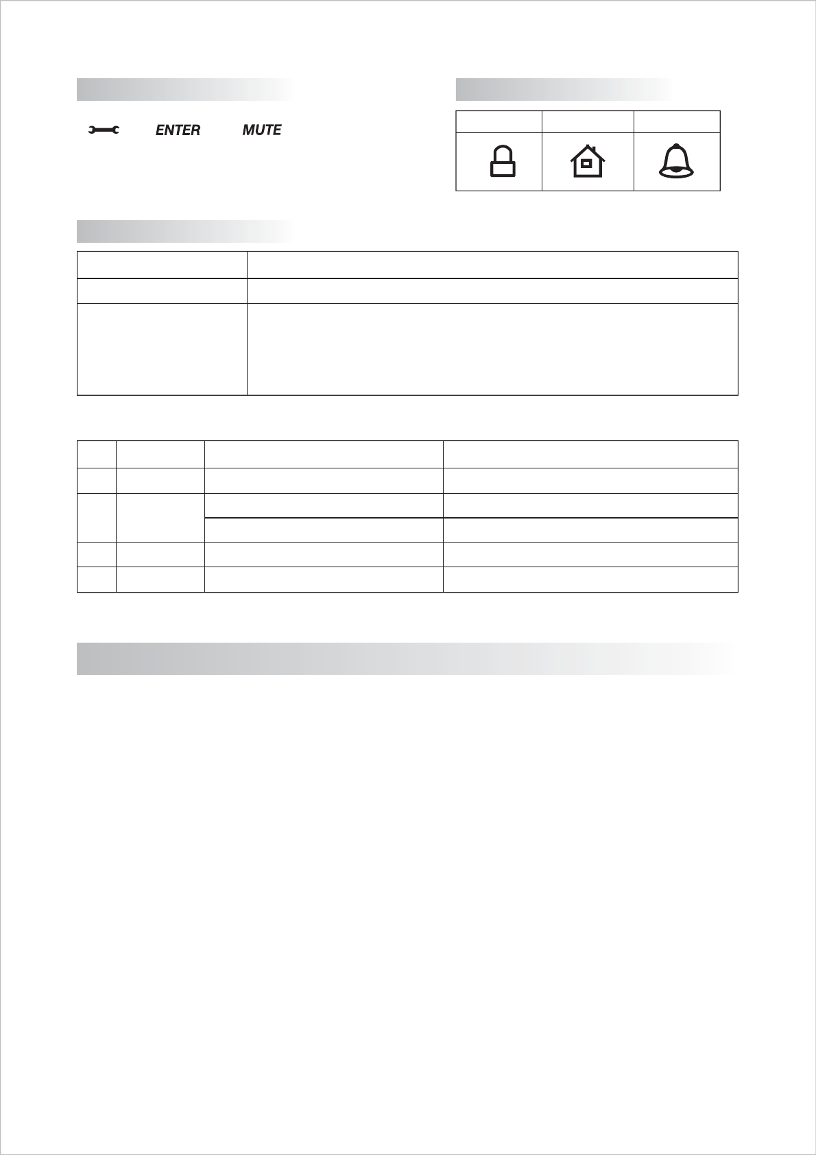
Programming Buttons:
Other:
Function Buttons:
ARM HOME ALERT
1
2
3
4
Mode
ARM
HOME
ALERT
OFF
WS101 BZ Sound (Zone triggering)
Siren
Siren
Chime
Chime
No response
Backlight Indication
Triggered – Red backlight will flash
Triggered – Red backlight will flash
Triggered – Green backlight will flash
Triggered – Green backlight will flash
Operating – Yellow backlight ON
Section 2 – Installing the Wire-free Home Protection System WS100S
2.1 Installing the Smart Panel WS101
Determine the location of the Smart Panel:
Note:
- The panel should be placed within a few feet of an electrical outlet.
- The panel should be easily accessible.
- The panel should not be placed near doors or windows that could be accessed by unintended users.
- The panel should not be placed near extreme temperature sources (ovens, stoves etc.) or near large metal objects that could
interfere with the wireless performance.
Once you have selected a location for the Smart Panel, you are ready to begin powering up the System.
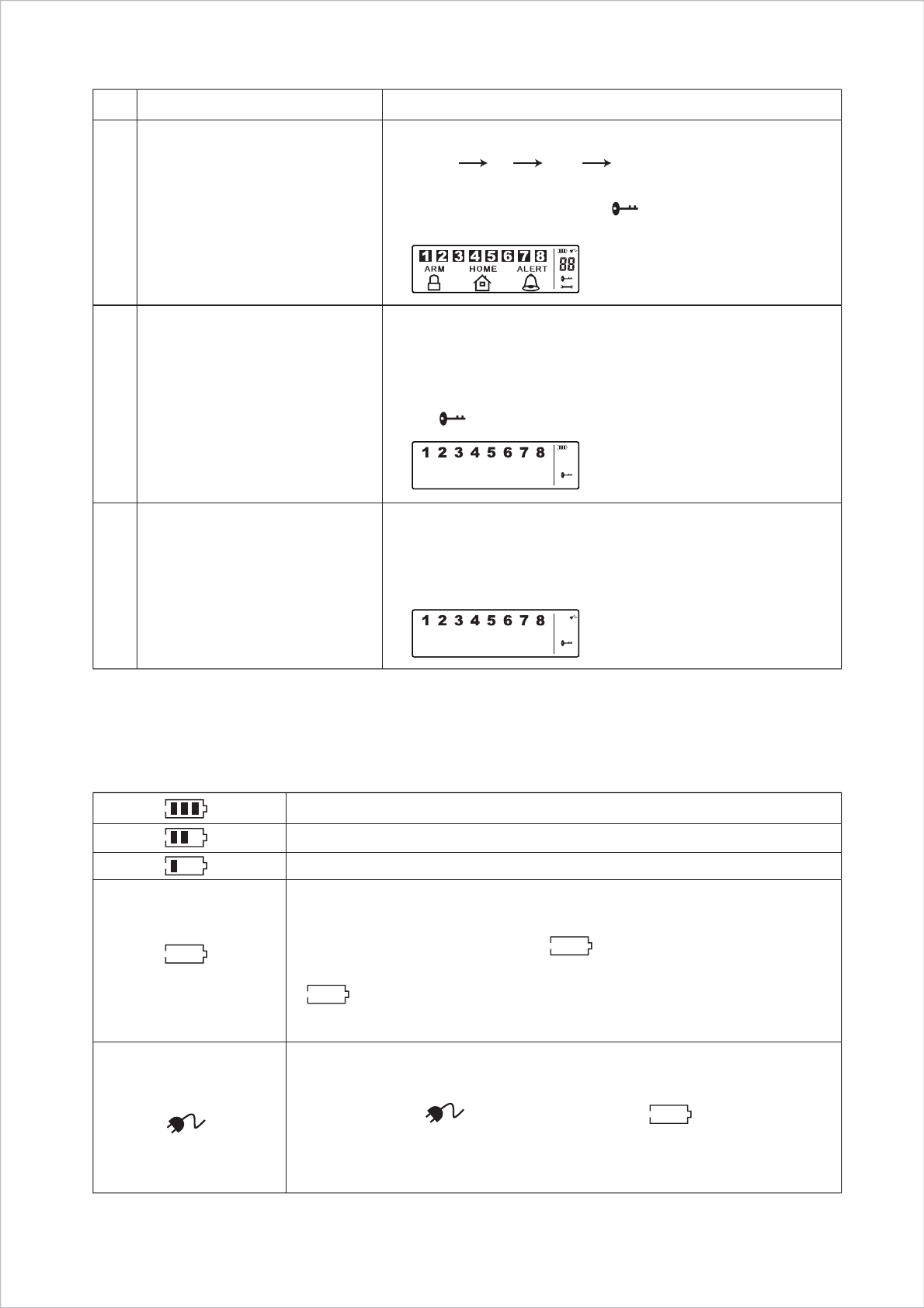
2.2 Powering up the Control Panel
Unscrew the battery compartment and remove the cover. Take out the LED demo socket and insert a new battery noting the
polarity as shown in the diagram below. Plug in the AC adaptor to the Smart Panel and connect it to a wall socket. Replace the
cover and the screw.
4
Low - battery voltage <7.0V
*Low battery will occur when the AC power supply is unplugged or interrupted.
9V battery functions as BACK UP and the symbol means LOW BATTERY
(battery voltage <7.0V). The LCD Backlight flashes yellow for 30 sec. and
will blink until the new battery is replaced or the AC power supply is
plugged in.
- You will hear one beep and the backlight will blink within 1 second
(Yellow Red Green Yellow)
- The Smart Panel will enter “OFF” mode after the automatic
self - checking is complete. Then will appear on the LCD screen.
- Enter the default 4-Digit PIN 1234
1
2
3
Description Note
Insert backup battery
(9V Alkaline – Not Included)
Battery Voltage low level
Plug in AC adapter to the DC socket
- OFF Mode (Keypad Lock)
- Power supply: Backup Battery
- * Make sure that you are in STANDBY Mode
- STANDBY Mode: Enter your 4-digit PIN, press "ENTER"
then will disappear.
System Entry “OFF” mode
- OFF Mode (Keypad Lock)
- Power supply: AC adapter
- Make sure that you are in STANDBY Mode
Go to STANDBY Mode: Enter your 4-Digit PIN
Note: The AC power supply must be plugged in at all times; a 9V battery functions as BACK UP power supply only when the AC
power supply is interrupted.
Power Supply = AC Adapter
*When the power sup ply switches from the battery to the AC Adaptor, the AC
symbol will appear ( ) and the Low Battery symbol ( ) will flash,
indicating that the Smart Panel backup battery is running low.
The backlight will be ‘ON’ while the AC adapter connects to the power supply.
2.3 Understanding the Battery and AC Adaptor Sym bols
Full - battery voltage > 9.0V
High - battery voltage <9.0V/>8.0V
Middle - battery voltage <8.0V/ >7.0V
5
You must be in STANDBY Mode.
*To make sure you are in STANDBY mode:
- Enter the factory default PIN 1 2 3 4
- Press ENTER
- The symbol " " will disappear
Section 3 – Using the Wire-Free Home Protection System WS100S
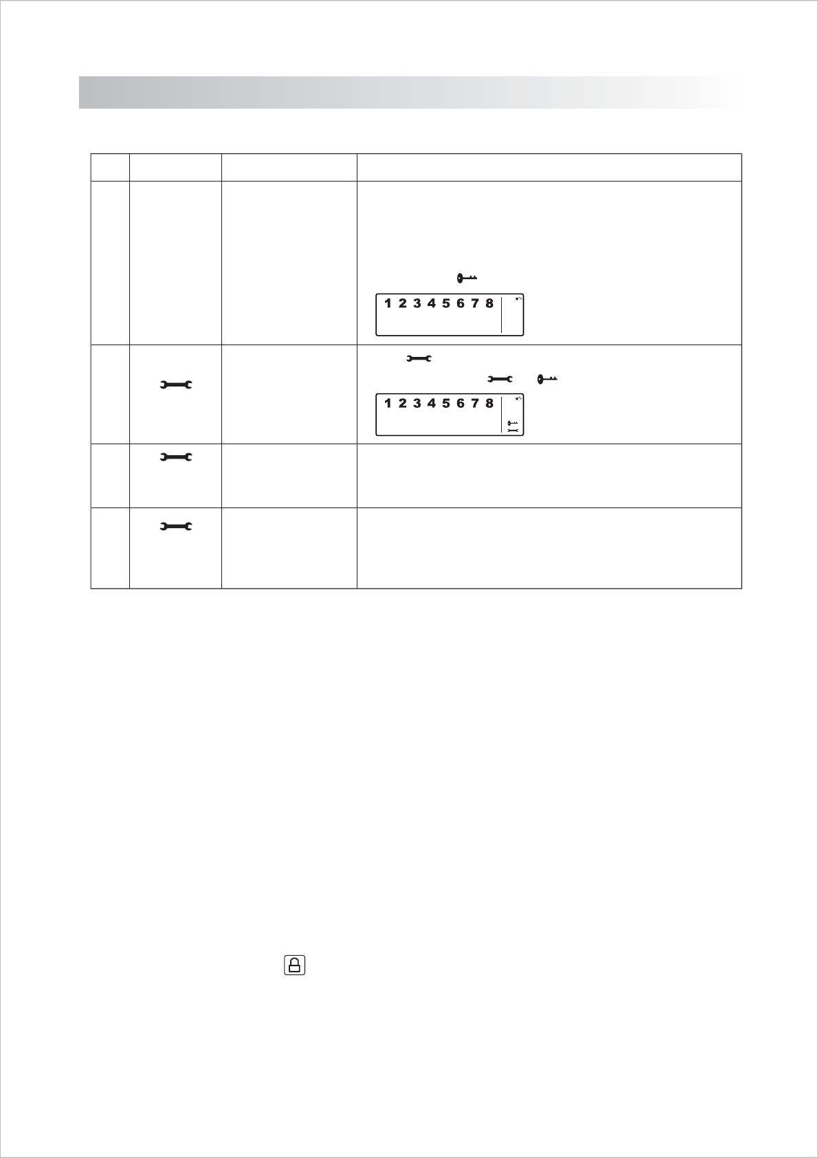
3.1 Programming your new 4-Digit PIN
“Standby ” Mode
1
Entering the new PIN Enter a 4-Dight PIN
* Choose from digits 0 to 9
Re-enter your 4-Dight PI
* One beep indicates that you entered a valid PIN; Three beeps indicate
that an invalid operation was performed.
Step Keys Description Note
1
2
3
4
1234
Enter
Setting the new PIN
4-Dight PIN
Enter
4-Dight PIN
Enter
Re-entering new PIN
for confirmation
Press then 1 to set the new PIN
The screen will show & symbols
3.2 Transmitting the Alarm Signal without a Siren
If you are forced to disarm the System, enter the Duress Password to stop the siren from sounding; the Smart Panel will silently
transmit the alarm signal to the optional sensors (Auto Dialer & Outdoor Bell Box) for help.
Duress Password:
Enter the default 4-Digit PIN = 1234+1
OR
Enter your personalized 4-digit PIN + 1
3.3 Operating different Modes
The system consists of 4 Operating Modes (STANDBY, ARM, ALERT, and HOME) to suit the user’s needs. You may select from
the 4 modes to be applied to the sensors.
3.3.1 STANDBY
If in Standby, the Smart Panel is prepared for mode selection.
3.3.2 ARM Mode
If in Arm Mode, the Smart Panel alarm will sound and a Red LED will flash when the system is triggered.
A. Arming the System
- On the Smart Panel: Enter your 4-Digit PIN + “ENTER” then press to activate.
- On the Remote Control: Press to activate.
6
B. Disarming the System
- On the Smart Panel: Enter your 4-Digit PIN followed by to disarm the system.
- On the Remote Control: Press to disarm the system
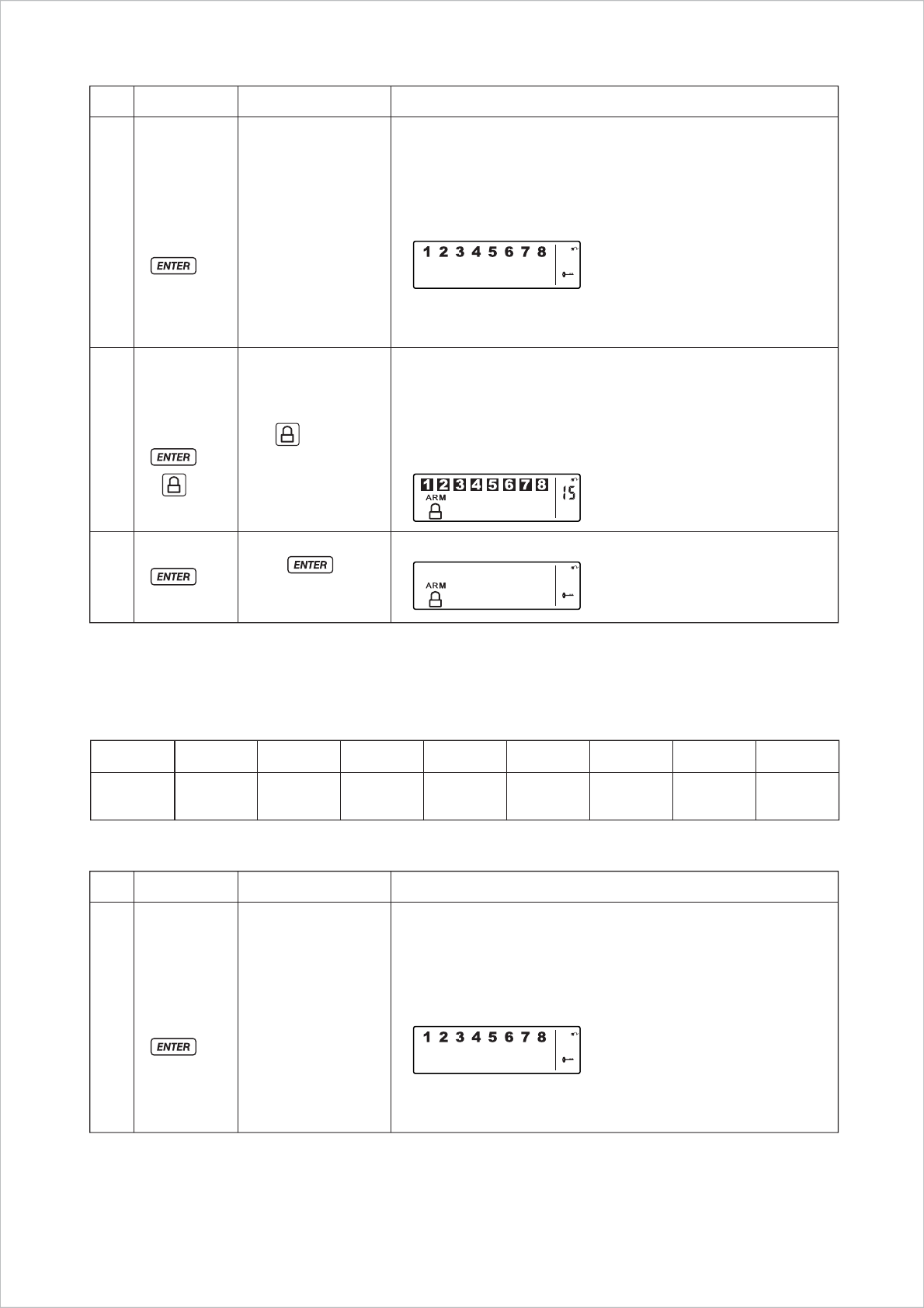
C. Zone Settings
Programming a Zone in each mode:
You must be in STANDBY Mode
*To make sure you are in STANDBY mode:
- Enter the default PIN 1 2 3 4 OR your new 4-Digit PIN
- Press ENTER.
- The LCD screen will display the below image:
Entry delay: up to 15 seconds
* There is a 15sec entry delay time with a visual count down before the
system is armed.
* If the Zone is enabled a number will appear as displayed in the image
below:
(One beep indicates that you entered a valid PIN; Three beeps indicate
that an invalid operation was performed).
“Standby ” Mode
Step Keys Description Note
1
2
3
(1234 /
4-DIGIT
PIN) +
4-DIGIT
PIN
Enter 4-DIGIT PIN
and for ARM
Mode
Press
to Complete
The System will enter ARM Mode after 15 seconds.
You must be in STANDBY Mode
*To make sure you are in STANDBY mode:
- Enter the default PIN 1 2 3 4 OR your new 4-Digit PIN
- Press ENTER.
- The LCD screen will display the below image:
(One beep indicates that you entered a valid PIN; Three beeps indicate
that an invalid operation was performed).
“Standby ” Mode
Step Keys Description Note
1
(1234 /
4-DIGIT
PIN) +
ZONE1 ZONE2 ZONE3 ZONE4 ZONE5 ZONE6 ZONE7 ZONE8
ARM
Mode ALARM ALARM ALARM ALARM ALARM ALARM ALARM ALARM
7
Sound: Alarm Siren (3minutes)
*To turn off the siren, enter the 4-Digit PIN or press on the remote
control to exit the current mode.
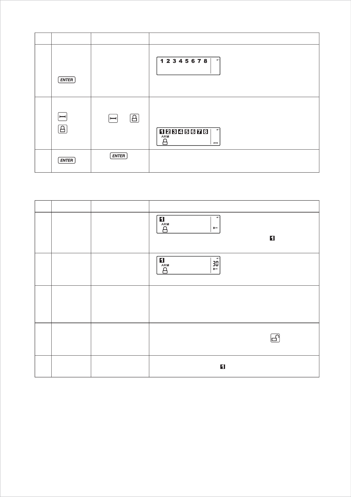
D. Triggers in ARM Mode
Press
to Complete the setting
After the setting is completed, return the Smart Panel to STANDBY for
mode selection.
LCD will shown per below:
Step Keys Description Note
2
1
3
4
Enter 4-DIGIT PIN
for setting
“ARM” Mode
Press then to
set the ARM mode
Step Keys Description Note
- Toggle 1, 2, 3, 4, 5, 6, 7, 8 to turn each zone ON or OFF
- If no number appears, the zone is turned OFF
- The LCD screen will display the below image:
4-DIGIT
PIN
(One beep indicates that you entered a valid PIN; Three beeps indicate
that an invalid operation was performed).
Example: Zone 1 trigger
Smart Panel’s alarm will sound and a Red LED and will flash
when the system is triggered.
2 System trigger
3 Entry delay 30 seconds
One beep indicates that the system is triggered.
There are 30secs. of entry delay time with visual count down for
disarming
Smart Panel’s alarm will sound and RED LED flashes when system
triggered without disarming in 30secs.
4The System sounds for
3 minutes
The Smart Panel Red LED & will flash until the system is disarmed.
5Return to ARM Mode
after the 3 minute siren
3.3.3 ALERT Mode
If in Alert mode, the Smart Panel chime will sound and a Green LED will flash when the system detects a visitor in the
protected area.
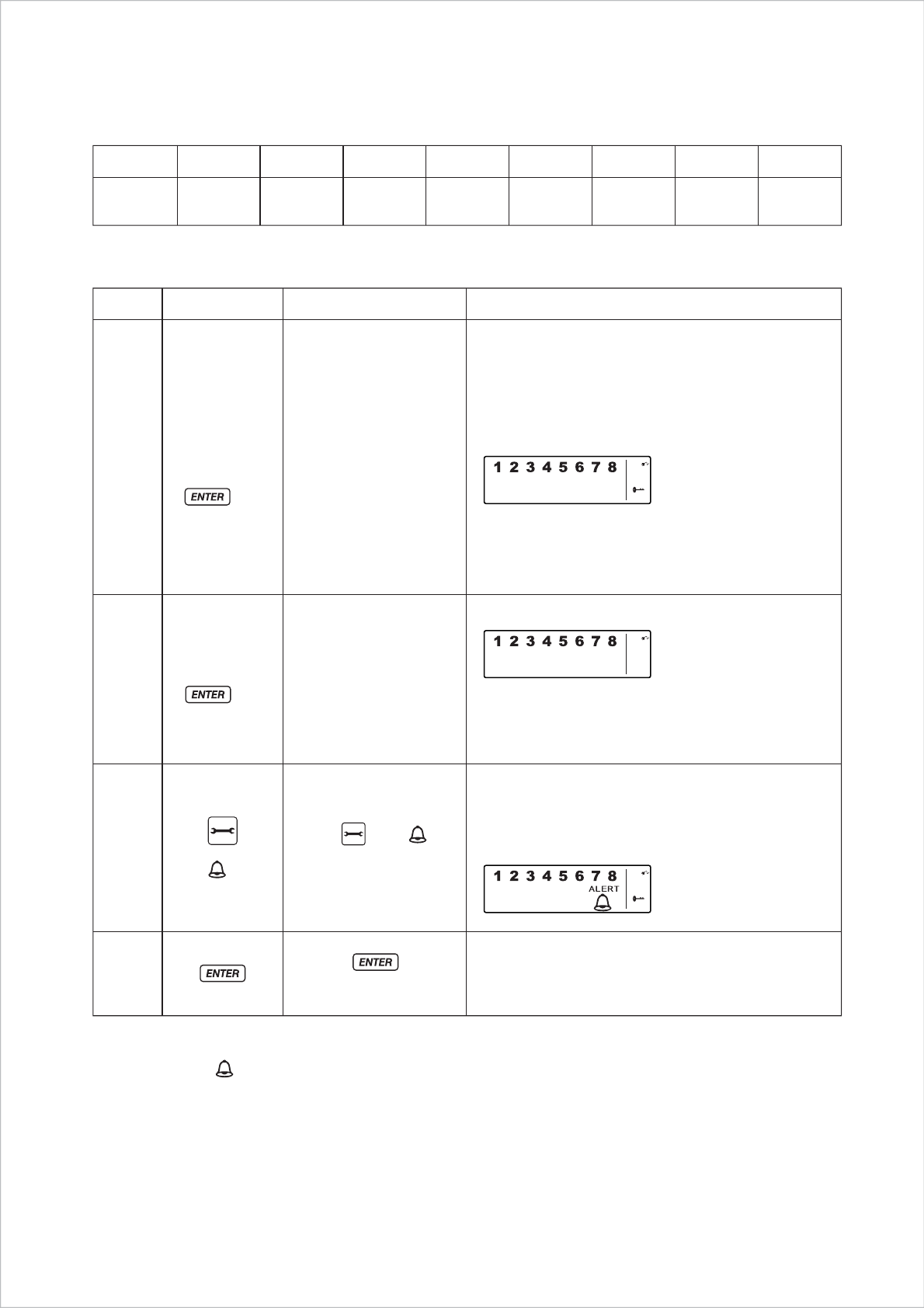
A. Entering ALERT Mode
- First make sure the Smart Panel is in STANDBY Mode
- On the Smart Panel: Enter your 4-Digit PIN + “ENTER” then press to activate.
- On the Remote Control: Press to activate.
8
ZONE1 ZONE2 ZONE3 ZONE4 ZONE5 ZONE6 ZONE7 ZONE8
ALERT
Mode
ALERT Disabled ALERT ALERT ALERT ALERT ALERT ALERT
B. Triggers in ALERT Mode
- Example: Zone setting:
Programming a Zone in each mode:
3.3.4 HOME Mode
There are default settings that allow the system to operate after opening the package. You can adjust the settings to
suit your needs. This mode allows the system operate in both the Arm and Alert Modes in different zones.
“Standby” Mode1
2
3
4
You must be in STANDBY mode
*To make sure you are in STANDBY mode:
- Enter default PIN 1 2 3 4 OR your new 4-Digit PIN
- Press ENTER
- The LCD screen will display the below image:
(One beep indicates that you entered a valid PIN;
Three beeps indicate that an invalid operation was
performed).
The LCD screen will display the below image:
Enter 4-DIGIT PIN for
setting (One beep indicates that you entered a valid PIN;
Three beeps indicate that an invalid operation was
performed).
Toggle 1, 2, 3, 4, 5, 6, 7, 8 to turn each zone ON or OFF
- If no number appears, the zone is turned OFF
- The LCD screen will display the below image:
After setting is completed, the Smart Panel will
return to STANDBY Mode, ready for mode
selection.
(1234 /
4-DIGIT PIN)
+
4-DIGIT PIN
Press to
complete the setting
Press then to
set the ALERT Mode
Keys Description NoteStep
9
Toggle 1, 2, 3, 4, 5, 6, 7, 8 to turn each zone in different mode
Indicates ALERT mode for a zone
Indicates ARM mode for a zone
Indicates the zone is turned OFF, number will not appear
- The LCD screen will display the below image:
A. Entering the HOME Mode
- First make sure the Smart Panel is in STANDBY Mode
- On the Smart Panel: Enter your 4-Digit PIN + “ENTER” then press to activate.
- On the Remote Control: Press to activate.
B. Triggers in HOME Mode
- Example: Zone setting:
Programming a Zone in each mode:
ZONE1 ZONE2 ZONE3 ZONE4 ZONE5 ZONE6 ZONE7 ZONE8
HOME
Mode
ALARM Disabled ALARM ALARM ALARM ALARM ALERT ALERT
(1234 /
4-DIGIT PIN)
+
4-DIGIT PIN Enter 4-DIGIT
PIN for setting
Press then
to set the
Alert mode
Press to
complete the setting
“Standby”
Mode
1
2
3
4
Keys Description NoteStep
HOME mode default setting:
ZoneDevice Status
(MODE)
WS102
WS102
WS103
Magnetic
Magnetic
PIR
1
2
8
ALERT
ALERT
ARM
Sensor
You must be in STANDBY Mode before any steps.
* To make sure you are in STANDBY Mode:
- Enter default PIN of 1 2 3 4 or your 4-Digit PIN
- Press ENTER
- The LCD screen will display the below image:
(One beep indicates that you entered a valid PIN;
Three beeps indicate that an invalid operation was performed).
- The LCD screen will display the below image:
(One beep indicates that you entered a valid PIN;
Three beeps indicate that an invalid operation was performed).
After setting is completed, the Smart Panel will return to
STANDBY Mode, ready for mode selection.
10
Section 4 – Installing the Sensors
4.1 Introduction to the Sensors
The Wire-Free Home Protection System WS100S allows you to expand your system at any time. The System includes a range
of sensors such as a 4-Button Key Fob Remote, a Door/Window Magnetic Sensor, a Motion Sensor, an Optional Auto Dialer,
an Outdoor Bell Box, a Mat Sensor, a Garage Door Sensor, an Inactivity Sensor, and a Shock Sensor.
The Wire-Free Home Protection System WS100S includes 3 wireless Sensors and 1 Key Fob Remote, which have a pre-
programmed default setting that begins working immediately once the battery is activated. It is advisable to install the main
package first and then personalize the settings once the System is functioning properly. This section should help you to
change the System settings in order to create a more personal home environment.
4.2 Installing the Sensors
First, determine the location of the sensors.
Note:
- The Sensors should not be easily accessible.
- The Sensors should be placed in the most vulnerable rooms or near key entry points.
- The Sensors should not be placed near extreme temperature sources (ovens, stoves etc.) or near large metal objects that
could interfere with the wireless performance.
Once you have selected a location for the Sensors, you are ready to begin powering up the System.
4.2.1 Installing the Door/Window Magnetic Sensor WS102
The wireless Magnetic Sensor consists of two pieces. The sensor detects when a door or a window is opened.
The two parts are fastened near the door or the window. One part functions as the transmitter and the other as the
magnet. Once the Magnetic Sensor is installed, any abnormality in the circuit will trigger an alert message that is
transmitted to the Smart Panel. The Magnetic Sensor is pre-programmed in Zone 1 and Zone 2; however, the settings
can be adjusted according to your needs. (See 2.4 Zone Setting)
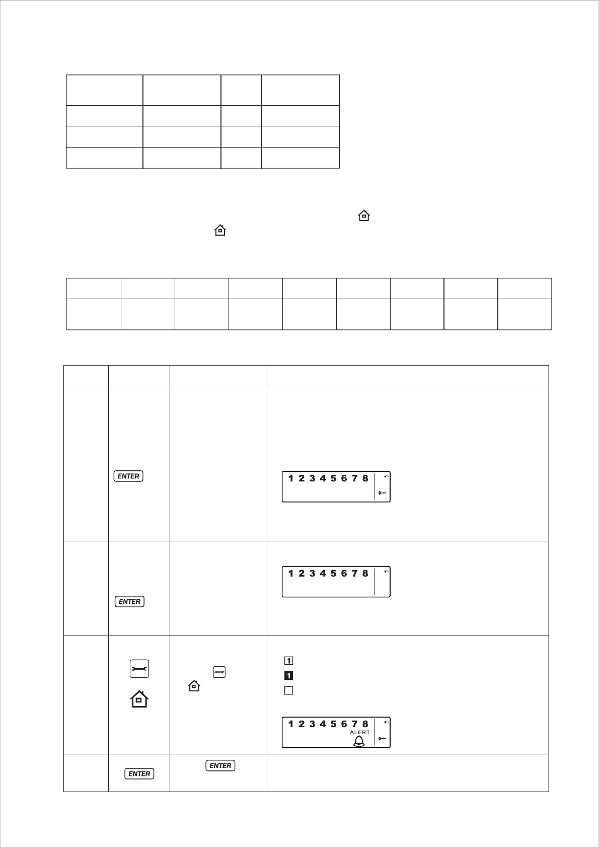
A. Powering up the the Door/Window Magnetic Sensor WS102
- Remove the battery cover; insert new batteries noting the polarity as shown in the diagram below; replace the
cover. (Requires 2 - AAA batteries, Not Included)
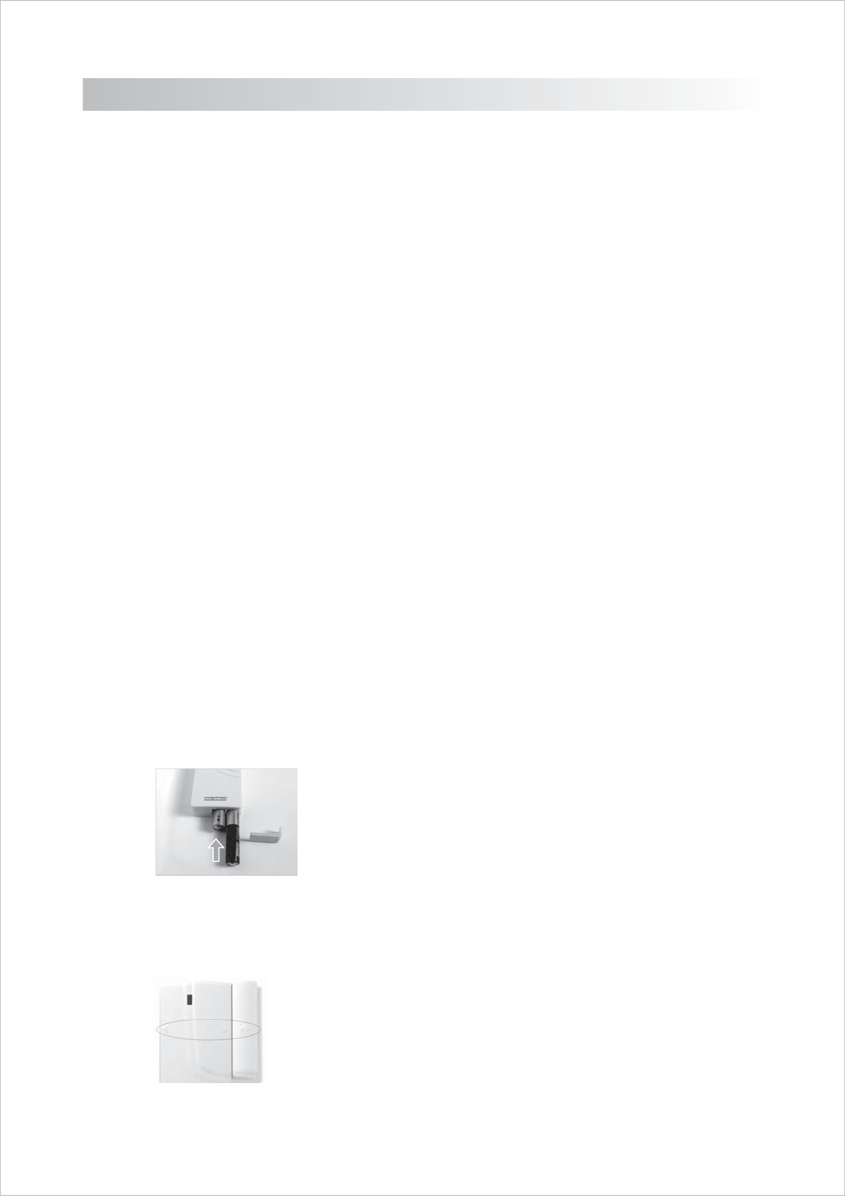
B. Installing the Door/Window Magnetic Sensor WS102
- Mount the transmitter on a fixed surface such as a door or a window frame.
- Mount the magnet on a movable surface such as a door or a window.
- The transmitter side marked with a “> / < “ must face the magnet
WS102
11
- The transmitter and the magnet must be no more than 0.5mm apart.
C. Mounting with the Double-Sided Adhesive
- Ensure the mounting surface is clean.
- Peel back one layer of the protective film and attach it to the transmitter.
- Peel back the remaining layer of protective film and press the transmitter firmly in place against the mounting
surface until firmly attached.
- Repeat to attach the magnet.
4.2.2 Installing the Motion Sensor WS103
The Wire-Free Home Protection System WS100S includes one Motion Sensor set described as a passive
infrared sensor (PIR). PIR sensors are designed to sense movement of anyone or anything that exceeds 36 kg
(80 lbs) in a given area. If less than 36 kg (80 lbs), not alert message is transmitted. Note: Pets larger than 36 kg
(80 lbs) must be no more than 1 meter high. It is best if pets are not allowed onto higher surfaces so that the s
sensors are not triggered unnecessarily. Also, the sensors become increasingly sensitive the closer the movement.
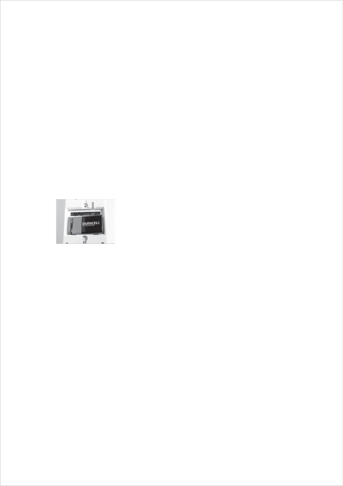
A. Powering up the Motion Sensor WS103
Remove the battery cover; insert a 9V battery noting the polarity as shown in diagram below; replace cover.
(Requires 1 - 9V battery, Not Included)
B. Installing the Motion Sensor WS103
- First, determine the location of the Motion Sensor.
Note:
- The Sensor should not be easily accessible.
- The Sensor should be placed in the most vulnerable rooms or near key entry points.
- Place the Sensor on a sturdy surface between 1.8m to 2.4mm (6ft to 8ft) from the floor.
- The Sensor should not be placed near extreme temperature sources (ovens, stoves etc.
- The Sensor should not be placed in direct sunlight.
- Do not install the Sensor outdoors or behind partitions.
You have the choice of attaching the Motion Sensor with screws or the adhesive provided.
C. Mounting using the Double-Sided Adhesive
- Ensure the mounting surface is clean.
- Peel back on layer of the protective film and attach it to the back of the Motion Sensor.
- Peel back the remaining layer of protective film and press the Motion Sensor firmly in place against the
mounting surface until firmly attached.
D. Mounting using Screws
- Hold the enclosed mounting template against the wall at the selected location and mark the points for drilling.
- Drill the holes and insert wall plugs.
- Attach the bracket to the mounting surface with the screws provided.
- Attach the Motion Sensor to the mounting bracket.
WS103
12
4.3 House Code and Zone Setting
The Wire-Free Home Protection System WS100S allows you can change the house security codes to avoid interference with
different combinations.
Step 1: Remove the battery compartment cover. You will find the 4 jumpers for setting the house security code. In most
cases you will not need to change the factory settings for the house security code. If the Smart Panel and sensors
activates intermittently or does not work at all, you may be able to solve the problem by changing your security code.
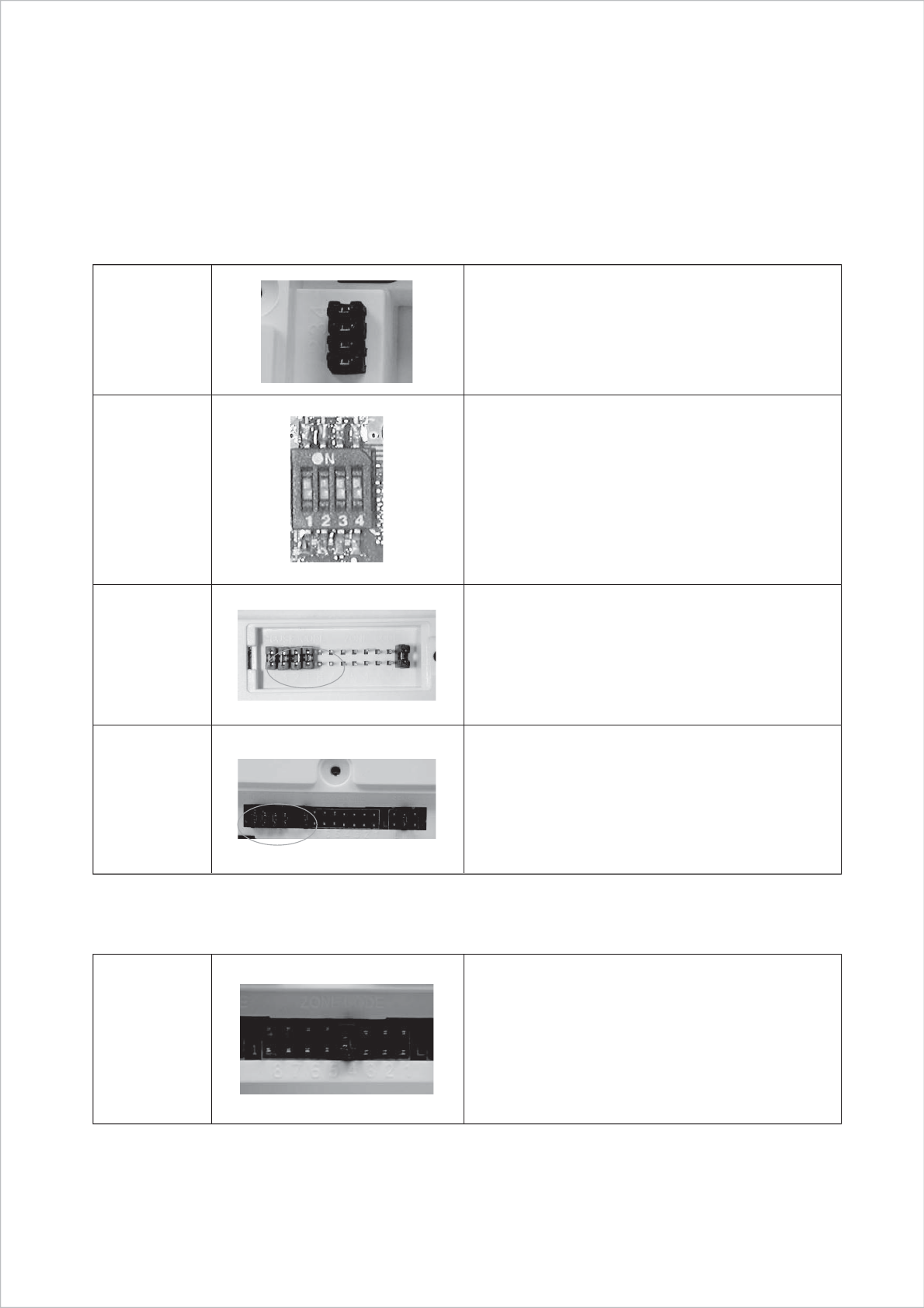
Step 2: Change the default settings of the Sensors
WS101
Jumper
WS101_TX
Dip-Switch
WS102
Jumper
WS103
Jumper
Smart Panel
House code: 1: closed, 2: closed, 3: closed, 4: closed
4-Button Key Fob Remote
House code: 1: closed, 2: closed, 3: closed, 4: closed
(To “ON” position)
Door/Window Magnetic Sensor
House code: 1: closed, 2: closed, 3: closed, 4: closed
Motion Sensor
House code: 1: closed, 2: closed, 3: closed, 4: closed
Zone Code
- Determinate the location of the Sensor in your home
- Pull out the Jumper and reassign it to the target zone
(zones 1 to 8)
- Replace and screw on the cover to complete the setting
change.

13
Section 5 - Troubleshooting
5.1 FQA
Q.1: What is the best way to set up my system? Where should I put my Smart Panel and the sensors?
A.1: We recommend that you take some time in advance to think about the placement of the Smart Panel and Sensors.
The best location for the Smart Panel is usually by the main entry/exit point, in a hallway, or in another central
location in your home. The Smart Panel must be plugged into a power socket, which may dictate where it can be
placed.
Please note that the alarm is pre-programmed with default settings, allowing you a pre-determined amount of time
to enter (30 seconds) and exit (15 seconds) before the alarm sounds. If the Smart Panel is not near your front door
you can either change the default setting to allow more time to enter/exit your home or, alternatively, use the Key
Fob to turn the system on and off.
Q.2: How many Sensors can the Smart Panel support?
A.2: An unlimited number of Sensors can be supported by the system; you can add the ‘Optional Sensors’ to different
zones in your house as you see fit.
Q.3: What wireless range should I expect from Sensors?
A.3: The range will vary depending on the type of structure; however, in an open space, the Sensors should be capable
of transmitting a signal up to 150 meters from the Smart Panel.
Q.4: How do I attach my Sensors?
A.4: Adhesive tape and screws are provided for the purpose of securely mounting these items. Please refer to the
User Guide for more information about mounting the Smart Panel and the Wireless Sensors.
Q.5: Do I have to programme the Smart Panel?
A.5: The Wire-Free Home Protection System WS100S is designed for easy self-installation. This means that the wireless
Sensors are in a default setting already registered to the Smart Panel and will therefore function immediately after
the Sensors are powered up. If you choose to buy additional accessories, these will need to be added to your
System using the easy to follow instructions.
Note: We recommend that you install the System using the default settings to ensure that your product functions
properly. Once you are familiar with the system you can change the settings to suit your needs.
Q.6: Can I still use the same System if I move?
A.6: The Wire-Free Home Protection System WS100S is completely portable. If you move, you can remove your
Smart Panel and wireless accessories and re-install them in your new property.
Q.7: What if I forget my PIN?
A.7: If you forget your PIN, you may press the “Reset” button inside the battery compartment and the PIN will be reset
to the factory default PIN 1234.
Q.8: Why does my Motion Sensor not respond to movement?
A.8: Motion Sensor are very sensitive so to preserve battery life the Sensor will go to “Sleep” after an event has been
identified and reported to the panel. This “Sleep” period lasts 3 minutes, after which, if no activity is detected,
the Motion Sensor will again become active and ready to detect other events.
Q.9: Why does my Motion Sensor keep generating false alarms?
A 9: If you have a pet, make sure they have not triggered the system. Remember, sensitivity to pets increases in certain
circumstances e.g. the nearer the pet to the Sensor.

14
5.2 Troubleshooting
AC Power Failure:
This may occur if your security system is accidentally unplugged or if there has been an AC power outage. If a full power
failure occurs, please contact your electric company to find out the source of the problem. The backup battery will continue
to run the system for approximately 6 hours.
System Battery Failure:
This may occur if the emergency backup battery has been drained and needs to be replaced. If AC power is not restored,
the Low Battery symbol will flash indicating that the Smart Panel backup battery is running low. The back up battery should
be replaced once the low battery symbol appears.
Sensor Failure:
This may occur if a sensor is not communicating with the Smart Panel. It is necessary for you to ensure the House Security
code Dipswitch and Jumpers of the Sensors are set correctly to the Smart Panel.
5.3 Alarm System Limitations
Even the most advanced alarm systems cannot guarantee 100% protection against burglary or environmental problems.
All alarm systems are subject to possible compromise or failure-to-warn for a variety of reasons.
Please note that you may encounter problems with your System if:
- The Sensors are not placed within hearing range of persons sleeping or remote parts of the premises.
- The Sensors are placed behind doors or other obstacles.
- Intruders gain access through unprotected points of entry (where sensors are not located).
- Intruders have the technical means of bypassing, jamming, or disconnecting all or part of the system.
- The power to the sensors is inadequate or disconnected.
- The Sensors are not located in proper environmental/temperature conditions i.e. too close to a heat source.
* Inadequate maintenance is the most common cause of alarm failure; therefore, test your system at least once per week
to be sure the Sensors and sirens are working properly.
* Although having an alarm system may make you eligible for reduced insurance premiums, the system is no substitute
for insurance.
WARNING: Security system devices cannot compensate for loss of life or property.
6.1 Product Information
Wireless systems are reliable and tested to high standards; however, it is important to consider that there are some limitations
due to their transmitting power and range:
- Receivers may be blocked by radio signals occurring on or near operating frequencies, regardless of the code selected.
- A receiver can only respond to one transmitted signal at a time.
- Wireless equipment should be tested regularly to determine whether there are sources of interference and to protect against
faults.
Section 6 – General Information

15
6.2 Specifications
6.2.1 Smart Panel WS101
Power source: 9V Alkaline battery x1pc
Sensor Numbers: Unlimited
House code: 4 Jumpers
Operating Frequencies: 433.92MHz +/-0.5MHz
6.2.2 4-Button Key Fob Remote WS101TX
Power source: 12V Alkaline battery x 1pc
RF Working transmission frequency: 433.92MHz +/-0.5MHz
Transmission power: > -45dBm(@12VDC, 1foot on the Lab table)
Buttons: “ARM”, “Home”, “Alert”, “OFF”; Panic function: “Home” + ”Alert”
House code: 4 Jumpers
Wireless Range to Smart Panel: >50M
6.2.3 Door/Window Magnetic Sensor WS102
Power source: “AAA” Alkaline battery 1.5V x 2pcs
RF Working transmission frequency: 433.92MHz +/-0.5MHz
Transmission power: > -28dBm(@3VDC, 1foot on the Lab table)
Battery low-level indicator: 2.3V +/-0.15V
LED Flashing: 1Hz+/-0.2Hz
Magnet sensor Gap activated: >11mm
House code: 4 Jumpers
Zone code: Pin header: 8 pin
Wireless Range to Smart Panel: >150M
6.2.4 Motion Sensor WS103
Power source: 9V Alkaline battery x1pc
RF Working transmission frequency: 433.92MHz +/-0.5MHz
Transmission power: > -18dBm(@9VDC, 1foot on the Lab table)
Battery low-level indicator: 7V +/-0.35V
LED Flashing: 1Hz+/-0.2Hz
PIR Detection angle: >110 Degree (@9VDC)
PIR Detection Range: “H”: > 15M “M”: >6M “L”: > 4M
PIR retrigger delay: 180s+/-30s (@9VDC)
Operating current: < 0.1mA
House code: 4 Jumpers
Zone code: Pin header: 8 pin
Wireless Range to Smart Panel: >150M
FCC WARNING
This device complies with Part 15 of the FCC Rules. Operation is
subject to the following two conditions:
(1) this device may not cause harmful interference, and
(2) this device must accept any interference received, including interference that may cause
undesired operation.
NOTE: The manufacturer is not responsible for and radio or TV interference caused by
unauthorized modifications to this equipment. Such modifications could void the user’s authority
to operate the equipment.