Smart Technologies and Investment SMARTWS102G25 DOOR/WINDOW SENSOR User Manual EBG21B1R1A001 BAH

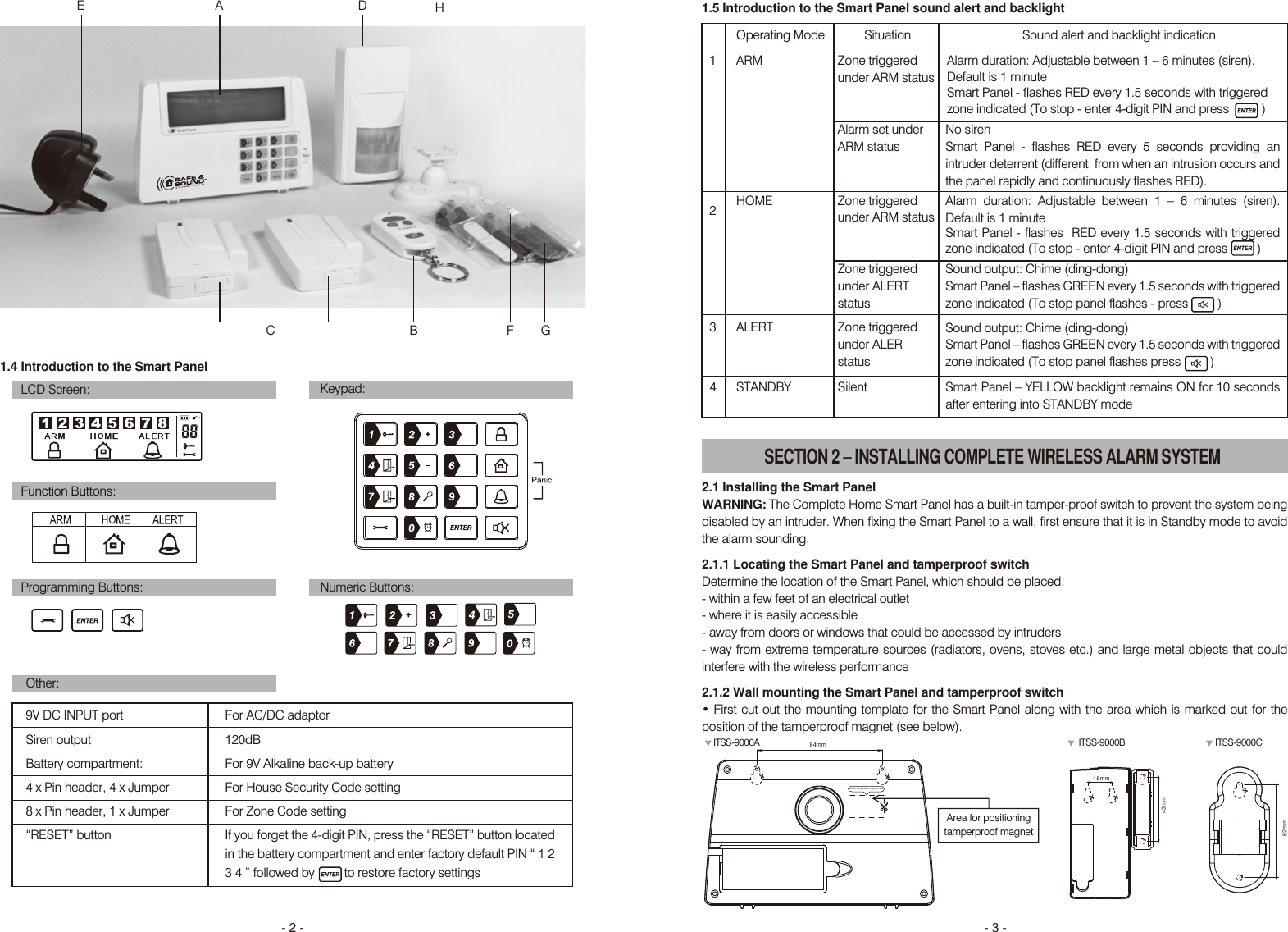
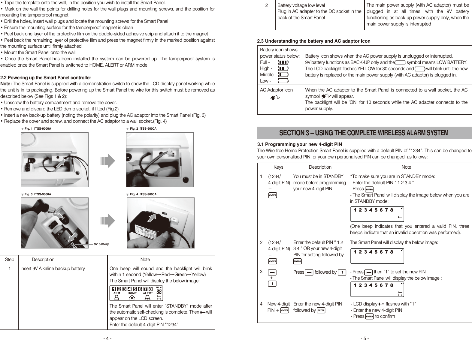
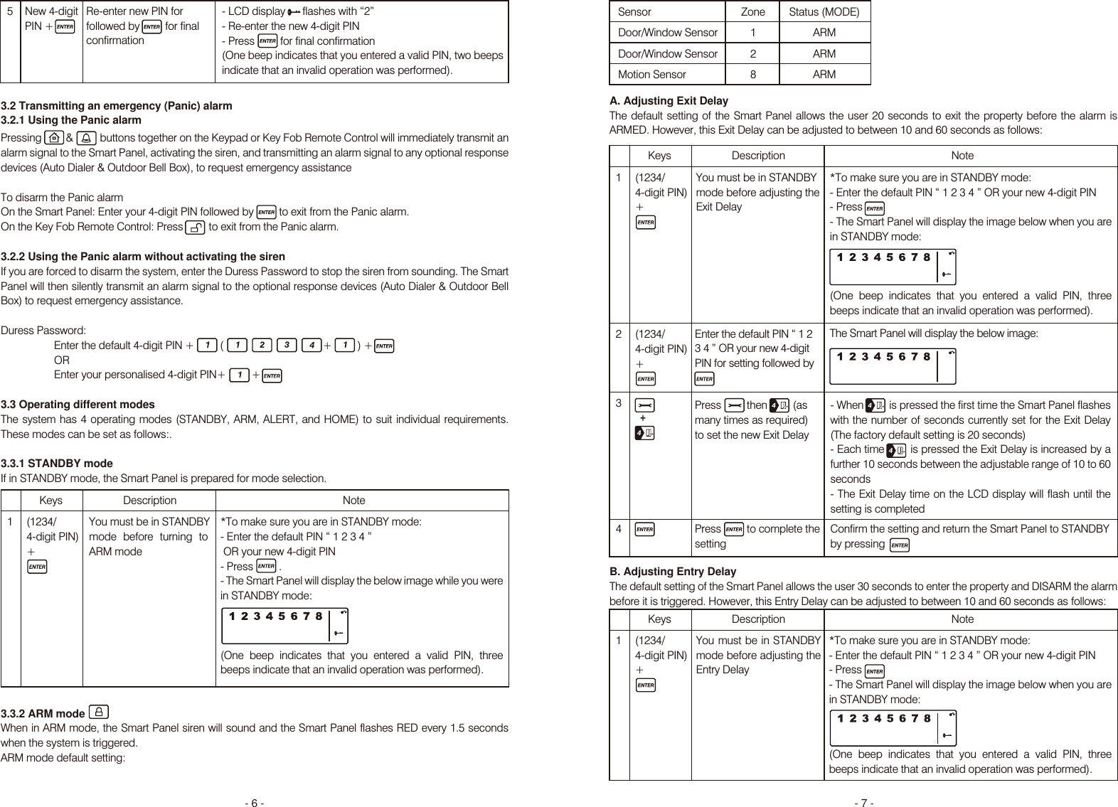
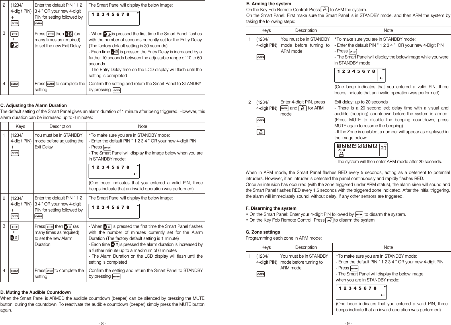
Smart Technologies & Investment Ltd DOOR/WINDOW SENSOR EBG21B1R1A001 BAH

Users Manual

ITSS-9000 USER GUIDECOMPLETE WIRELESS ALARM SYSTEM Section 1 – Getting started1.1 General system overview1.2 Introduction to the system1.3 Items included with the system1.4 Introduction to the Smart Panel 1.5 Introduction to the Smart Panel backlightSection 2 – Installing the Complete Wireless Alarm System2.1 Installing the Smart Panel 2.2 Powering up the Smart Panel 2.3 Understanding the battery and AC adaptor iconSection 3 – Using the Complete Wireless Alarm System3.1 Programming your 4-digit PIN3.2 Transmitting an emergency (Panic) alarm3.2.1 Using the Panic alarm 3.2.2 Using the Panic alarm without activating the siren3.3 Operating different modes 3.3.1 STANDBY mode3.3.2 ARM modeA. Adjusting Exit DelayB. Adjusting Entry DelayC. Adjusting the Alarm DurationD. Muting the Audible CountdownE. Arming the systemF. Disarming the systemG. Zone settingsH. Triggers in ARM mode3.3.3 ALERT modeA. Entering the ALERT modeB. Exiting the ALERT modeC. Zone settings3.3.4 HOME modeA. Entering the HOME modeB. Exiting the HOME modeC. Zone settings Section 4 – Installing the Sensors4.1 Introduction to the Sensors 4.2 Installing the Sensors4.2.1 Installing the Door/Window SensorA. Powering up the the Door/Window SensorB. Installing the Door/Window SensorC. Mounting with the double-sided adhesive pad4.2.2 Installing the Motion Sensor A. Powering up the Motion Sensor B. Installing the Motion SensorC. Sensor sensitivity D. Walk testE. Mounting using screws4.2.3 Introduction of Key Fob Remote ControlA. IntroductionCONTENTS13513ITSS-9000A Smart PanelITSS-9000B Window SensorITSS-9000C Motion SensorITSS-9000D Remote Control
B. Operationi. Powering up the Key Fob Remote Controlii. Enrolling the Remote Control onto the Smart Paneliii. Operating the Key Fob Remote Controliv. Deleting a Remote Control from the Smart Panelv. Querying the ID Number of a Remote Control4.3 House Security Code settings4.4 Zone Code settings Section 5 - Troubleshooting5.1 FAQ5.2 Troubleshooting   Section 6 – General Information6.1 Product information6.2 Specifications 6.2.1 Smart Panel 6.2.2 Key Fob Remote Control6.2.3 Door/Window Sensor 6.2.4 Motion Sensor 6.3 Maintenance6.4 BatteriesSection 7 – FCC STATEMENTSection 8 – Premium 24/7/365 Central Station Monitoring Available.SECTION 1 – GETTING STARTED1.1 General system overviewCAUTION! The 9V battery in the Smart Panel is for power back-up purposes only, and the unit should be supplied with main  power (through the AC adaptor) at all times. Difficulty in disarming the Smart Panel in ALARM mode may occur when it is powered by the back-up battery alone. This is not a malfunction, and can be resolved by the use of a fresh 9V battery and main power supplied through the AC adaptor included.IMPORTANT! Due to the strong signal of the alarm, we advise that you change the House Security Code settings (explained in Section 4.3), if you suspect that one of your in-range neighbors may also be using this type of alarm systemAlarm system limitationsEven the most advanced alarm systems cannot guarantee 100% protection against burglary or environmental problems. All alarm systems are subject to possible compromise or failure-to-warn for a variety of reasons.* Please note that you may encounter problems with your system if: once per week ensure the sensors and siren(s) are working properly.*Although having an alarm system may make you eligible for reduced insurance premiums, the system is no substitute for insurance.WARNING: Security system devices cannot compensate for loss of life or property.1.2 Introduction to the systemfeatures. The system is controlled by a Smart Panel, which gathers information from wireless sensors placed inside and at the entry points of your home or office. If the Smart Panel detects a security breach, indicator lights will flash and the siren(s) will sound. Details of how to correctly install and operate the system are contained within this User Guide.1.3 Items included with the systemPlease check that all of the following items were included in the package before installing the system: A. Smart Panel ITSS-9000A   B. Key Fob Remote Control ITSS-9000D               C. Door/Window Sensors ITSS-9000B D. Motion Sensor ITSS-9000C                                E. AC adaptor for Smart PanelF. Double-sided adhesive strips for Door/Window Sensor        G. Screws, wall plugs, tamperproof magnet and double-sided adhesive strip for Smart Panel                           H. Mounting bracket for Motion Sensor19212223- 1 -
Sound output: Chime (ding-dong)Smart Panel – flashes GREEN every 1.5 seconds with triggered zone indicated (To stop panel flashes - press         )1.4 Introduction to the Smart Panel 1.5 Introduction to the Smart Panel sound alert and backlightLCD Screen:Function Buttons:Programming Buttons: Numeric Buttons:Keypad:Other:9V DC INPUT portSiren outputBattery compartment:4 x Pin header, 4 x Jumper8 x Pin header, 1 x Jumper“RESET” buttonFor AC/DC adaptor120dB For 9V Alkaline back-up battery  For House Security Code settingFor Zone Code settingIf you forget the 4-digit PIN, press the “RESET” button located in the battery compartment and enter factory default PIN “ 1 2 3 4 ” followed by         to restore factory settingsOperating ModeARM SituationZone triggered under ARM statusAlarm duration: Adjustable between 1 – 6 minutes (siren). Default is 1 minuteSmart Panel - flashes RED every 1.5 seconds with triggered zone indicated (To stop - enter 4-digit PIN and press          )Sound alert and backlight indication 1Alarm set underARM statusNo sirenSmart Panel - flashes RED every 5 seconds providing an intruder deterrent (different  from when an intrusion occurs and the panel rapidly and continuously flashes RED).Alarm duration: Adjustable between 1 – 6 minutes (siren). Default is 1 minuteSmart Panel - flashes  RED every 1.5 seconds with triggered zone indicated (To stop - enter 4-digit PIN and press         )HOME Zone triggeredunder ARM status2Zone triggeredunder ALERTstatusSound output: Chime (ding-dong)Smart Panel – flashes GREEN every 1.5 seconds with triggered zone indicated (To stop panel flashes press         )ALERT Zone triggeredunder ALERstatus3Smart Panel – YELLOW backlight remains ON for 10 seconds after entering into STANDBY modeSTANDBY Silent4SECTION 2 – INSTALLING COMPLETE WIRELESS ALARM SYSTEM 2.1 Installing the Smart PanelWARNING: The Complete Home Smart Panel has a built-in tamper-proof switch to prevent the system being disabled by an intruder. When fixing the Smart Panel to a wall, first ensure that it is in Standby mode to avoid the alarm sounding.  2.1.1 Locating the Smart Panel and tamperproof switchDetermine the location of the Smart Panel, which should be placed: - within a few feet of an electrical outlet- where it is easily accessible- away from doors or windows that could be accessed by intruders- way from extreme temperature sources (radiators, ovens, stoves etc.) and large metal objects that could interfere with the wireless performance 2.1.2 Wall mounting the Smart Panel and tamperproof switch          position of the tamperproof magnet (see below).A D HBCEGFMount tamperproof magnet here84mm62mm43mm16mmArea for positioningtamperproof magnet- 3 -- 2 -ITSS-9000A ITSS-9000B ITSS-9000C
- LCD display       flashes with “1”- Enter the new 4-digit PIN- Press         to confirmKeys(1234/ 4-digit PIN)+DescriptionYou must be in STANDBYmode before programmingyour new 4-digit PINEnter the default PIN “ 1 23 4 ” OR your new 4-digit PIN for setting followed by The Smart Panel will display the below image: - Press         then “1” to set the new PIN- The Smart Panel will display the below image :Note1234SECTION 3 – USING THE COMPLETE WIRELESS ALARM SYSTEMmounting the tamperproof magnetthe mounting surface until firmly attached                 enabled once the Smart Panel is switched to HOME, ALERT or ARM mode2.2 Powering up the Smart Panel controllerNote: The Smart Panel is supplied with a demonstration switch to show the LCD display panel working while the unit is in its packaging. Before powering up the Smart Panel the wire for this switch must be removed as described below (See Figs 1 & 2):Fig. 2  ITSS-9000A9V batteryFig. 1  ITSS-9000AFig. 3  ITSS-9000A Fig. 4  ITSS-9000AStep1Description NoteInsert 9V Alkaline backup battery  One beep will sound and the backlight will blink within 1 second (YellowėRedėGreenėYellow) The Smart Panel will display the below image:  The Smart Panel will enter “STANDBY” mode after the automatic self-checking is complete. Then       will appear on the LCD screen. Enter the default 4-digit PIN “1234” 2 Battery voltage low levelPlug in AC adapter to the DC socket in the back of the Smart PanelThe main power supply (with AC adaptor) must be plugged in at all times, with the 9V battery functioning as back-up power supply only, when the main power supply is interruptedBattery icon shows when the AC power supply is unplugged or interrupted.9V battery functions as BACK-UP only and the            symbol means LOW BATTERY. The LCD backlight flashes YELLOW for 30 seconds and            will blink until the new battery is replaced or the main power supply (with AC adaptor) is plugged in.When the AC adaptor to the Smart Panel is connected to a wall socket, the AC symbol          will appear.  The backlight will be ‘ON’ for 10 seconds while the AC adapter connects to the power supply.2.3 Understanding the battery and AC adaptor iconBattery icon showspower status below: Full -     High -    Middle -  Low -  AC Adaptor icon3.1 Programming your new 4-digit PINThe Wire-free Home Protection Smart Panel is supplied with a default PIN of “1234”. This can be changed to your own personalised PIN, or your own personalised PIN can be changed, as follows:(1234/ 4-digit PIN)+Press         followed by  *To make sure you are in STANDBY mode: - Enter the default PIN “ 1 2 3 4 ”  - Press  - The Smart Panel will display the image below when you are in STANDBY mode:  (One beep indicates that you entered a valid PIN, three beeps indicate that an invalid operation was performed). New 4-digitPIN +Enter the new 4-digit PIN followed by - 5 -- 4 -
SensorDoor/Window SensorDoor/Window SensorMotion SensorZone128Status (MODE)ARMARMARMA. Adjusting Exit DelayThe default setting of the Smart Panel allows the user 20 seconds to exit the property before the alarm is ARMED. However, this Exit Delay can be adjusted to between 10 and 60 seconds as follows:B. Adjusting Entry DelayThe default setting of the Smart Panel allows the user 30 seconds to enter the property and DISARM the alarm before it is triggered. However, this Entry Delay can be adjusted to between 10 and 60 seconds as follows:Keys(1234/ 4-digit PIN)+DescriptionEnter the default PIN “ 1 23 4 ” OR your new 4-digit PIN for setting followed by The Smart Panel will display the below image: Note1234(1234/ 4-digit PIN)+*To make sure you are in STANDBY mode: - Enter the default PIN “ 1 2 3 4 ” OR your new 4-digit PIN - Press  - The Smart Panel will display the image below when you are in STANDBY mode:  (One beep indicates that you entered a valid PIN, three beeps indicate that an invalid operation was performed).Press         to complete thesetting Keys(1234/ 4-digit PIN)+Description Note1*To make sure you are in STANDBY mode: - Enter the default PIN “ 1 2 3 4 ” OR your new 4-digit PIN - Press         .- The Smart Panel will display the below image while you were in STANDBY mode:  (One beep indicates that you entered a valid PIN, three beeps indicate that an invalid operation was performed).- LCD display      flashes with “2”- Re-enter the new 4-digit PIN- Press         for final confirmation(One beep indicates that you entered a valid PIN, two beepsindicate that an invalid operation was performed).5 New 4-digitPIN +Re-enter new PIN for followed by         for final confirmation3.2 Transmitting an emergency (Panic) alarm 3.2.1 Using the Panic alarm Pressing         &          buttons together on the Keypad or Key Fob Remote Control will immediately transmit an alarm signal to the Smart Panel, activating the siren, and transmitting an alarm signal to any optional response To disarm the Panic alarmOn the Smart Panel: Enter your 4-digit PIN followed by         to exit from the Panic alarm. On the Key Fob Remote Control: Press         to exit from the Panic alarm.3.2.2 Using the Panic alarm without activating the sirenIf you are forced to disarm the system, enter the Duress Password to stop the siren from sounding. The Smart Panel will then silently transmit an alarm signal to the optional response devices (Auto Dialer & Outdoor Bell Duress Password:  Enter the default 4-digit PIN +         (                                   +         ) + OR   Enter your personalised 4-digit PIN+         +3.3 Operating different modes        These modes can be set as follows:. 3.3.1 STANDBY modeIf in STANDBY mode, the Smart Panel is prepared for mode selection. You must be in STANDBY mode before turning to ARM mode3.3.2 ARM modeWhen in ARM mode, the Smart Panel siren will sound and the Smart Panel flashes RED every 1.5 seconds when the system is triggered.ARM mode default setting: You must be in STANDBY mode before adjusting the Exit DelayPress         then         (as to set the new Exit Delay- When         is pressed the first time the Smart Panel flashes with the number of seconds currently set for the Exit Delay (The factory default setting is 20 seconds)- Each time        is pressed the Exit Delay is increased by a further 10 seconds between the adjustable range of 10 to 60 seconds- The Exit Delay time on the LCD display will flash until the setting is completedConfirm the setting and return the Smart Panel to STANDBY by pressingKeys(1234/ 4-digit PIN)+Description Note1*To make sure you are in STANDBY mode: - Enter the default PIN “ 1 2 3 4 ” OR your new 4-digit PIN - Press  - The Smart Panel will display the image below when you are in STANDBY mode:  (One beep indicates that you entered a valid PIN, three beeps indicate that an invalid operation was performed).You must be in STANDBY mode before adjusting the Entry Delay- 7 -- 6 -
- When        is pressed the first time the Smart Panel flashes with the number of seconds currently set for the Entry Delay (The factory default setting is 30 seconds)- Each time         is pressed the Entry Delay is increased by a further 10 seconds between the adjustable range of 10 to 60 seconds- The Entry Delay time on the LCD display will flash until the setting is completedKeys(1234/ 4-digit PIN)+DescriptionYou must be in STANDBYmode before adjusting theExit DelayEnter the default PIN “ 1 23 4 ” OR your new 4-digit PIN for setting followed by Press         then         (as to set the new Alarm DurationThe Smart Panel will display the below image:  Note1234(1234/ 4-digit PIN)+*To make sure you are in STANDBY mode: - Enter the default PIN “ 1 2 3 4 ” OR your new 4-digit PIN - Press  - The Smart Panel will display the image below when you are in STANDBY mode:  (One beep indicates that you entered a valid PIN, three beeps indicate that an invalid operation was performed).- When        is pressed the first time the Smart Panel flashes with the number of minutes currently set for the Alarm Duration (The factory default setting is 1 minute)- Each time         is pressed the alarm duration is increased by a further minute up to a maximum of 6 minutes- The Alarm Duration on the LCD display will flash until the setting is completedConfirm the setting and return the Smart Panel to STANDBY by pressing Keys(1234/ 4-digit PIN)+DescriptionEnter 4-digit PIN, press            and         for ARM modeNote12(1234/ 4-digit PIN)++*To make sure you are in STANDBY mode: - Enter the default PIN “ 1 2 3 4 ”  OR your new 4-Digit PIN - Press- The Smart Panel will display the below image while you were in STANDBY mode:  (One beep indicates that you entered a valid PIN, three beeps indicate that an invalid operation was performed).Exit delay: up to 20 seconds- There is a 20 second exit delay time with a visual and audible (beeping) countdown before the system is armed. (Press MUTE to disable the beeping countdown, press MUTE again to resume the beeping)- If the Zone is enabled, a number will appear as displayed in the image below:   - The system will then enter ARM mode after 20 seconds.Press        to complete the setting Keys(1234/ 4-digit PIN)+DescriptionYou must be in STANDBY mode before turning to ARM modeNote1*To make sure you are in STANDBY mode: - Enter the default PIN “ 1 2 3 4 ” OR your new 4-digit PIN - Press  - The Smart Panel will display the below image:when you are in STANDBY mode:  (One beep indicates that you entered a valid PIN, three beeps indicate that an invalid operation was performed).Enter the default PIN “ 1 23 4 ” OR your new 4-digit PIN for setting followed by The Smart Panel will display the below image: 234(1234/ 4-digit PIN)+Press         to complete thesetting Press         then         (as to set the new Exit DelayConfirm the setting and return the Smart Panel to STANDBY by pressingC. Adjusting the Alarm Duration The default setting of the Smart Panel gives an alarm duration of 1 minute after being triggered. However, this alarm duration can be increased up to 6 minutes:D. Muting the Audible CountdownWhen the Smart Panel is ARMED the audible countdown (beeper) can be silenced by pressing the MUTE button, during the countdown. To reactivate the audible countdown (beeper) simply press the MUTE button again.E. Arming the systemOn the Key Fob Remote Control: Press         to ARM the system.On the Smart Panel: First make sure the Smart Panel is in STANDBY mode, and then ARM the system by taking the following steps:You must be in STANDBY mode before turning to ARM modeWhen in ARM mode, the Smart Panel flashes RED every 5 seconds, acting as a deterrent to potential intruders. However, if an intruder is detected the panel continuously and rapidly flashes RED.Once an intrusion has occurred (with the zone triggered under ARM status), the alarm siren will sound and the Smart Panel flashes RED every 1.5 seconds with the triggered zone indicated. After the initial triggering, the alarm will immediately sound, without delay, if any other sensors are triggered.F. Disarming the system  G. Zone settingsProgramming each zone in ARM mode:20- 9 -- 8 -
Keys(1234/ 4-digit PIN)+DescriptionYou must be in STANDBY mode before turning to ALERT modeEnter 4-digit PIN, press         and          for ALERT mode- The system will then enter ALERT mode - If the Zone is enabled, a number will appear as displayed inthe image below: Note124-digit PIN+  + *To make sure you are in STANDBY mode: - Enter the default PIN 1 2 3 4 OR your new 4-digit PIN - Press  - The Smart Panel will display the below image when in STANDBY mode:  (One beep indicates that you entered a valid PIN, three beeps indicate that an invalid operation was performed).Enter 4-digit PIN for setting followed byPress         then          to set the ARM modeThe Smart Panel will display the below image:2344-digit PIN)+- Toggle 1, 2, 3, 4, 5, 6, 7, 8 to turn each zone ON or OFF- If no number appears, the zone is turned OFF- The Smart Panel will display the below image:Confirm the setting and return the Smart Panel to STANDBY by pressing Press         to complete thesetting H. Triggers in ARM modeExample: Zone 1 triggerStep1Description NoteUnder the “ARM” Mode2 System triggerThe Smart Panel will display the below image:One beep indicates that the system is triggered.3 Entry delay 30 seconds There are 30 seconds of entry delay time with a visual countdown for disarming.Once an intrusion has occurred (zone triggered under ARM status), the alarm siren will sound for 1 minute and the Smart Panel flashes RED every 1.5 seconds with the triggered zone indicated, until the system is disarmed.*To disarm the system, enter the 4-Digit PIN or press       on the remote control.4 Return to ARM mode after the initial triggeringAfter the initial triggering, the alarm will immediately sound, without delay, if any other sensors are triggered. 3.3.3 ALERT modeIf in Alert mode, the Smart Panel chime will sound and the Smart Panel flashes GREEN every 1.5 seconds with the triggered zone indicated, when the system detects a visitor in the protected area. ALERT mode default setting: A. Entering ALERT modeSensorDoor/Window SensorDoor/Window SensorMotion SensorZone128Status (MODE)ALERTALERTALERTmode by taking the following steps:Keys(1234/ 4-digit PIN)+DescriptionYou must be in STANDBY mode before turning to ALERT modeEnter 4-digit PIN for setting followed by  The Smart Panel will display the below image:  (One beep indicates that you entered a valid PIN, three beepsindicate that an invalid operation was performed).Note124-digit PIN+  You must be in STANDBY mode *To make sure you are in STANDBY mode: - Enter default PIN 1 2 3 4 OR your new 4-digit PIN- Press  - The Smart Panel will display the below image: (One beep indicates that you entered a valid PIN, three beeps indicate that an invalid operation was performed).Press         then         to set the ALERT ModeToggle 1, 2, 3, 4, 5, 6, 7, 8 to turn each zone ON or OFF- If no number appears, the zone is turned OFFThe Smart Panel will display the below image:  3B. Exiting the ALERT modeC. Zone settingsProgramming each zone in ALERT mode:- 11 -- 10 -
SECTION 4 – INSTALLING  THE SENSORSEnter 4-digit PIN for settingfollowed by  Press         then         to set the HOME modeThe Smart Panel will display the below image:(One beep indicates that you entered a valid PIN, three beepsindicate that an invalid operation was performed).2344-digit PIN)+Toggle 1, 2, 3, 4, 5, 6, 7, 8 to turn each zone in different mode     Indicates ALERT mode for a zone     Indicates ARM mode for a zone     Indicates the zone is turned OFF, number will not appearThe Smart Panel will display the below image:(One beep indicates that you entered a valid PIN three beeps indicate that an invalid operation was performed).Confirm the setting and return the Smart Panel to STANDBY by pressing Press         to complete thesetting SensorDoor/Window SensorDoor/Window SensorMotion SensorZone128Status (MODE)ALERTALERTARMKeys(1234/ 4-digit PIN)+DescriptionYou must be in STANDBY mode before turning to HOME modeEnter 4-digit PIN, press          and          for HOME modeNote124-digit PIN+  + *To make sure you are in STANDBY mode: - Enter the default PIN 1 2 3 4 OR your new 4-digit PIN - Press  The Smart Panel will display the below image while in STANDBY mode:  (One beep indicates that you entered a valid PIN, three beeps indicate that an invalid operation was performed).- Then system will enter HOME mode - If the Zone is enabled, a number will appear as displayed in the image below: Press          to complete thesetting Confirm the setting and return the Smart Panel to STANDBY by pressing 43.3.4 HOME mode  There are default settings that allow the system to operate after opening the package. These settings can ARM and ALERT modes in different zones.HOME mode default setting: A. Entering the HOME modeby taking the following steps: B. Exiting the HOME mode C. Zone settingsProgramming each zone in HOME mode:Keys(1234/ 4-digit PIN)+DescriptionYou must be in STANDBY mode before turning to HOME modeNote1You must be in STANDBY Mode before any steps.* To make sure you are in STANDBY mode: - Enter default PIN of 1 2 3 4 or your 4-digit PIN - Press  - The LCD screen will display the below image: 4.1 Introduction to the Sensors This package includes 3 wireless sensors which have a pre-programmed default setting that begins working immediately once the battery is activated (the Key Fob Remote Control needs to be enrolled onto the system before it can operate – see Section 4.2.3). It is advisable to install the main package first and then personalise the settings once the system is functioning properly. This section should help you to change the system settings in order to create a more personal home environment. 4.2 Installing the SensorsFirst, determine the location of the sensors.*Note: The sensors should be placed:- where they are not easily accessible.- in the most vulnerable rooms or near key entry points. - away from extreme temperature sources (radiators, ovens, stoves etc.) and large metal objects that could interfere with the wireless performance. - where better RF performance can be achieved (if necessary).Once you have selected a location for the Sensors, the system can be powered up.4.2.1 Installing the Door/Window Sensor The Door/Window Sensor consists of two parts, a transmitter and a magnet. Once this sensor is installed, and the two parts are fastened onto the door or window, the sensor will trigger and transmit a message to the Smart Panel when the door or window is opened. One Door/Window Sensor is pre-programmed in Zone 1 and 3.3 & 4.4 Zone Settings) - 13 -- 12 -
A. Powering up the the Door/Window Sensor  Remove the battery cover; insert new batteries noting the polarity as shown in the diagram below and replace the cover. (Rees 2 x AAA batteries not included)  Low battery indication: If the batteries need to be replaced, the RED LED on the transmitter will flash slowly.      B. Installing the Door/Window Sensor Mount the transmitter on a fixed surface such as a door or a window frame. Mount the magnet on a movable surface such as a door or a window. Ensure the >/< marks on the sides of the transmitter and magnet match up as shown in the diagram.   The transmitter and the magnet must be no more than 5mm apartC. Mounting with the double-sided adhesive pad Ensure the mounting surface is clean. Peel back one layer of the protective film and attach it to the transmitter. Peel back the remaining layer of protective film and press the transmitter firmly in place against the mounting surface until firmly attached. Repeat to attach the magnet.4.2.2 Installing the Motion Sensor The Motion Sensor is designed to sense movement in a given area.Note: It is best if pets are not allowed onto higher surfaces so that the sensors are not triggered unnecessarily (no more than 1 metre high). A. Powering up the Motion Sensor  Remove the battery cover, insert and connect a 9V ( 6LR61) battery( not included ) as shown in diagram below and replace the cover. Rees 1 x 9V ( 6LR61) battery( not included ) Low battery indication: If the batteries need to be replaced, the RED LED will flash (not including entry / exit delay flashing). B. Installing the Motion SensorFirst, determine the location of the Motion Sensor.*Note: The Sensor should be placed: - in the most vulnerable rooms or near key entry points. - on a solid surface between 1.8m to 2.4mm (6ft to 8ft) from the floor.- away from extreme temperature sources (radiators, ovens, stoves etc.)- away from direct sunlight. - indoors only and not behind partitions- where better RF performance can be achieved (if necessary)C. Sensor sensitivityIMPORTANT! The Motion Sensor is designed with a built-in sleep timer to save battery power.  If there is no movement in front of the PIRs for 3 minutes, the PIRs will become ‘ready to signal’ and movement will now be reported.  The Motion Sensor will sleep for 3 minutes after reporting.   Any movement detected in sleep time will not be reported, please bear this in mind during system set up.The sensitivity of the Motion Sensor is adjustable and can be changed by setting the connector, found in the battery compartment, on either the “High”, “Middle” or “Low” position. When the sensitivity is set to “Low”, more movement is reed to trigger the sensor. It is recommended to set the sensitivity to “Low” and perform a “Walk Test” (Described in part D). If the walk test result is satisfactory, the sensitivity does not ree further adjustment.  If the walk test result shows the sensitivity is too low, then the sensitivity can be set to “Middle” or “High” as reed. It is recommended that a walk test be conducted after each change in sensitivity setting. Test Motion Sensor by pressing the test button inside the battery compartment.     D. Walk testAfter mounting the sensor at the desired location, it is important to perform a walk test in order to determine if the sensor is detecting the correct area. The distance at which the sensor can detect motion can be adjusted by altering the angle of the sensor.  To reduce the detection range, simply move the sensor downward and move the sensor upward to maximize the range.Note: Enter into ALERT mode before you perform the walk test, so that the alarm is not triggered.You should walk in the area that you would like the sensor to monitor.  If movement is detected the red light inside the unit will appear.  If the red light does not appear, adjust the mounting angle accordingly.  Perform the walk test again after 3 minutes.  Repeat this procedure until motion is detected.  While carrying out the test, there should be no movement in the detection area during the 3 minutes interval.* Tips: The sensor should not face towards direct sunlight, be placed near heat or cold producing devices (i.e. air conditioning, radiators, fans, ovens, heaters etc.) that may cause false triggers.  Also perform the walk test in areas which the sensor is not intended to cover, to ensure movement cannot be detected. E. Mounting using screws Hold the enclosed mounting template against the wall at the selected location and mark the points for drilling. Drill the holes and insert wall plugs. Attach the bracket to the mounting surface with the screws provided. Attach the Motion Sensor to the mounting bracket. 4.2.3 Introduction of Key Fob Remote ControlA. IntroductionThe Complete Home Complete Wireless Alarm System Remote Control allows you to operate the systems Smart Panel remotely, from inside or outside the property. Using the control the system can be armed or disarmed and the siren can be activated instantly if reed (using the Panic function).  B. Operationi. Powering up the Key Fob Remote ControlThe Remote Control includes a 12V(MN27) alkaline battery. To activate, unscrew and remove the back of the Remote Control, and carefully remove the clear plastic insulation tab from the battery. If the battery is dislodged, replace it noting the correct polarity as shown inside the battery compartment. Replace the battery cover.ii. Enrolling the Remote Control onto the Smart PanelNote: Before being able to use the Key Fob Remote Control supplied with the system, or any additional Remote Controls, they first need to be enrolled (added onto the system) as follows: - 15 -- 14 -
Press        then        to enter the Remote Control Enroll mode. Then press any key on the new Remote Control to enrol it onto the system.Keys(1234/ 4-digit PIN)+DescriptionYou must be in STANDBY mode before enrolling a new Remote Control onto the Smart PanelEnter the default PIN “ 1 2 3 4 ” OR your new 4-digit PIN for setting followed by  The Smart Panel will display the below image:Note1234(1234/ 4-digit PIN)+*To make sure you are in STANDBY mode: - Enter the default PIN “ 1 2 3 4 ” OR your new 4-digit PIN - Press  - The Smart Panel will display the image below when you are in STANDBY mode:  (One beep indicates that you entered a valid PIN, three beeps indicate that an invalid operation was performed).- LCD display flashes the ID no. of the remote to be enrolled e.g. when enrolling the first remote ID no. “01” will flash. Once the first remote is enrolled the “02” will flash ready for a second remote to be enrolled (One beep indicates that the remote was enrolled to the Smart Panel successfully)Note: It is recommended that the ID No. is marked on the remote in case it needs to be deleted at a later stageConfirm the enrolment and return the Smart Panel to STANDBY by pressing Confirm the deletion and return the Smart Panel to STANDBY by pressing Press         to complete the enrolmentKeys(1234/ 4-digit PIN)+DescriptionThe Smart Panel will display the below image:Note1234(1234/ 4-digit PIN)+*To make sure you are in STANDBY mode: - Enter the default PIN “ 1 2 3 4 ” OR your new 4-digit PIN - Press  - The Smart Panel will display the image below when you are in STANDBY mode:  (One beep indicates that you entered a valid PIN, three beeps indicate that an invalid operation was performed).- LCD display flashes the total number of remote currently enrolled to the system(e.g. If the Smart Panel has 3 remotes enrolled the LCD display will flash “03”)- Input the remote ID no. (e.g. “02”) for the remote you wish to delete (Inputting “00” will delete all remote controls)- LCD display will then flash the total number of remotes enrolled after deletion(One beep indicates that the remote was successfully deleted from the Smart Panel)Press         to complete the deletioniii. Operating the Key Fob Remote ControlThe remote can be used to arm, disarm, and operate the system instantly.ARM – Pressing the ARM button on the remote will arm the system, triggering the preset exit delay. When triggered the Smart Panel’s LED light will flash Red and indicate the triggered zone.DISARM – Pressing the DISARM button on the remote will disarm the system instantly and the system will return to Standby mode.ALERT – Pressing the ALERT button on the remote will put the system into Alert mode and a chime will sound if any of the sensors are triggered. The Green light on the Smart Panel LED display will flash and indicate the triggered zone.HOME – Pressing the HOME button on the remote will set the system in Home mode which will operate the system in both Arm and Alert modes in different preset zones.PANIC – If the HOME and ALERT buttons are pressed together the systems alarm is immediately activatedYou must be in STANDBY mode before deleting a Remote Control from theSmart PanelEnter the default PIN “ 1 2 3 4 ” OR your new 4-digit PIN for setting followed byPress         then         to enter the Remote Control Deleting mode. Then input the ID no. of the Remote Control you wish to delete from the systemKeys(1234/ 4-digit PIN)+Description Note1*To make sure you are in STANDBY mode: - Enter the default PIN “ 1 2 3 4 ” OR your new 4-digit PIN - Press  - The Smart Panel will display the image below when you are in STANDBY mode:  (One beep indicates that you entered a valid PIN, three beeps indicate that an invalid operation was performed).You must be in STANDBY mode before deleting a Remote Control from theSmart PanelThe Smart Panel will display the below image:2 (1234/ 4-digit PIN)+Enter the default PIN “ 1 2 3 4 ” OR your new 4-digit PIN for setting followed by  v. Querying the ID Number of a Remote ControlThe ID number of a Remote Control device can be identified as follows:iv. Deleting a Remote Control from the Smart PanelIf a Remote Control device is damaged or lost, it can be deleted from the system as follows:- 17 -- 16 -
SECTION 5 - TROUBLESHOOTING34- After entering into Remote Querying mode, the LCD display will flash the total number of remote controls currently enrolled to the system(e.g. If 3 remotes are enrolled the LCD display will flash “03”)- The ID No. of the Remote can then be checked by pressing any key on the remote (e.g, if the LCD display flashes “02” then that is the ID of the remote)by pressingPress         to complete the Press         then         to go into Remote Querying mode, and then press any key on the remote to check its ID.4.3 House Security Code settingsIn most cases the factory settings of the House Security Code will NOT need to be changed.However, if the Smart Panel and Sensors activate intermittently or do not work at all, this may be due to interference with other systems, which can be avoided by changing the House Security Code. To change this code, take the following steps with each system module:.  1) There are 4 Jumpers/Dip-switches on each device. To locate these remove the battery compartment cover.2) Then set the Jumpers as shown below (ON-Push in / OFF –Pull out) to change the House Security Code setting. Make sure the Jumpers on the Smart Panel and its Sensors exactly match each other AND the Dip-switch setting on the Key Fob Remote Control.4.4 Zone Code settings Sensors are supplied with pre-assigned Zone settings to make setup easy – the Door/Window Sensors are pre-assigned to Zones 1 & 2 and the Motion Sensor to Zone 8.To assign a Sensor to a different zone, the Zone Code on the Sensor needs to be changed. To change this code, take the following steps:1) There is a Zone Code Jumper on each Sensor which can be located by removing the Jumper compartment cover.2) Then pull out the Jumper and reassign it to the new Zone (Zones 1 to 8) as shown in the diagram below.3) Replace and screw back the cover to complete the Zone Code setting.- Smart Panel- Each sensorDefault House Security Code: 1: ON, 2: ON, 3: ON, 4: ON*Jumper: ON = Pushed in, OFF = Pulled outJumpers for House Security CodeDip-switches for House Security CodeJumper for ZoneCode- Key Fob Remote ControlDefault House Security: 1: ON, 2: ON, 3: ON, 4: ONDefault zone code:Door/Window sensor – Zone 1Door/Window sensor – Zone 2Motion sensor – Zone 85.1 FAQsQ.1:  What is the best way to set up my system? Where should I put my Smart Panel and the sensors?A.1:  We recommend that you take some time in advance to think about the placement of the Smart Panel and Sensors. The best location for the Smart Panel is usually by the main entry/exit point, in a hallway, or in another central location in your home. However, it must be plugged into a power socket, which may dictate where it can be placed. of time to enter (30 seconds) and time to exit (20 seconds) before the alarm sounds. front door you can either change the default setting to allow more time to enter/exit your home or, alternatively use the Key Fob to disarm the system.Q.2: How many Sensors can the Smart Panel support?A.2. An unlimited number of sensors can be supported by the system, added to different zones in your house, as you see fit.Q.3: What wireless range should I expect from Sensors?A.3: The range will vary depending on the type of structure; however, in an open space, the sensors should be capable of transmitting a signal up to 150 metres from the Smart Panel.  Determine the location of the sensors first and change to a different location for better RF performance.Q.4: How do I attach my Sensors?A.4: Adhesive tape and screws are provided for the purpose of securely mounting these items. Please refer to the user guide for more information about mounting the Smart Panel and the wireless sensors.Q.5: Do I have to programme the Smart Panel?A.5: The Complete Wireless Alarm System is designed for easy installation. This means that the wireless sensors are in a default setting already registered to the Smart Panel and will therefore function immediately after the sensors are powered up. If you choose to buy additional accessories, these will need to be added to your system using the easy to follow instructions.*Note: Due to the strong signal of the alarm, we advise that you change the House Security Code settings following section 4.3 of this manual, if you suspect that one of your in-range neighbors may also be using this alarm system.  Q.6: Can I still use the same system if I move?A.6. The Complete Wireless Alarm System is completely portable. If you move, you can remove your Smart Panel and wireless accessories and re-install them in your new property.  Q.7: What if I forget my PIN?A.7: If you forget your PIN, you may press the “Reset” button inside the battery compartment of the Smart Panel and the PIN will be reset to the factory default PIN 1234.Q.8:  Why does my Motion Sensor not respond to movement?A.8: Motion Sensor are very sensitive so to preserve battery life the Sensor will go to “Sleep” after an event has been identified and reported to the panel.  This “Sleep” period lasts 3 minutes, after which, if no activity is detected, the Motion Sensor will again become active and ready to detect other events.Q.9: Why does my Motion Sensor keep generating false alarms?A 9: If you have a pet, make sure they have not triggered the system.  Remember, sensitivity to pets increases in certain circumstances e.g. the nearer the pet to the Sensor. - 19 -- 18 -
SECTION 6 – GENERAL INFORMATION5.2 Troubleshooting AC power failure:This may occur if your security system is accidentally unplugged or if there has been a main power cut. If a full power failure occurs, please contact your electric company to find out the source of the problem. The back-up battery will continue to run the system for approximately 6 hours. System battery failure:This may occur if the emergency back-up battery has been drained and needs to be replaced. If AC power is not restored, the low battery symbol will flash indicating that the Smart Panel back-up battery is running low. The back-up battery should be replaced once the low battery symbol appears.Sensor failure:This may occur if a sensor is not communicating with the Smart Panel. It is necessary for you to ensure the House Security Code dipswitch and jumpers of the sensors are set correctly to the Smart Panel. 6.1 Product Information Wireless systems are reliable and tested to high standards; however, it is important to consider that there are some limitations due to their transmitting power and range:code selected.-   A receiver can only respond to one transmitted signal at a time.to protect against faults.6.2 Specifications 6.2.1 Smart Panel Power source:     AC adaptorBack up power:        9V ( 6LR61 ) alkaline battery x1pcSensor numbers:       UnlimitedHouse Code:     4 Jumpers   Siren output:                                                               120dB (Duration-adjustable) 6.2.2 Key Fob Remote ControlPower source:         12V ( MN27 ) alkaline battery x 1pc  House Code:     4 JumpersWireless range to Smart Panel:      <65 meters (open area)   6.2.3 Door/Window SensorPower source:         AAA ( LR03 ) alkaline battery 1.5V x 2pcs  House Code:     4 Jumpers Zone Code:         Pin header: 8 pinWireless range to Smart Panel:      <150 metres (open area)  6.2.4 Motion Sensor Power source:         9V ( 6LR61 ) alkaline battery x1pc  PIR detection angle:       <110 Degree (@9VDC)PIR detection range:                                      “H”:< 15M “M”:< 6M “L”:< 4M House Code:     4 Jumpers Zone Code:         Pin header: 8 pinWireless range to Smart Panel:     <150 meters (open area)Power saving timer:      3 minutes6.3 MaintenanceThe product may be cleaned with a soft damp cloth and then wiped dry.  Do not use abrasive, solvent based or aerosol cleaners as this may damage and/or discolor the product.  Do not allow water to enter or attempt to clean the inside of the unit.6.4 BatteriesDo not allow batteries to corrode and leak as this may cause permanent damage to the product.Take care to insert the batteries with the correct polarity as shown inside the battery compartments.Do not mix new and old batteries or different types of batteries.Do not fit rechargeable batteries.At the end of their useful life the batteries should be disposed of via a suitable Recycling Centre. Do not dispose of with your normal household waste. DO NOT BURN.- 21 -- 20 -
FCC STATEMENT- 23 -- 22 -Operation is subject to the following two conditions:(1) this device may not cause interference, and(2) this device must accept any interference, including interference      that may cause undesired operation of the device."2. Changes or modifications not expressly approved by the party responsible  for compliance could void the user’s authority to operate the equipment.NOTE: This equipment has been tested and found to omply with the limits for a Class B digital device, pursuant to Part 15 of the FCC Rules. These limits aredesigned to provide reasonable protection against harmful interference in aresidential installation. This equipment generates, uses and can radiate radiofrequency energy and, if not installed and used in accordance with theinstructions, may cause harmful interference to radio communications. However,there is no guarantee that interference will not occur in a particular installation.If this equipment does cause harmful interference to radio or television reception,which can be determined by turning the equipment off and on, the user isencouraged to try to correct the interference by one or more of the followingmeasures:-- Reorient or relocate the receiving antenna.-- Increase the separation between the equipment and receiver.-- Connect the equipment into an outlet on a circuit differentfrom that to which the receiver is connected.-- Consult the dealer or an experienced radio/TV technician for help.1. This device complies with Part 15 of the FCC Rules.
Innovative Technology Electronics Corp.Limited Warranty: 90 Days Labor, One Year Parts Innovative Technology Electronics Corp. (IT) warrants the product to be free from “Defects” in materials under normal use for a period of “One Year” from the date of the original purchase. The Warranty is “Not” transferable. IT agrees, within the initial “90 Day” period, to repair or replace the product if it is determined to be defective at “No Charge”. It is further agreed that IT will cover the cost to repair or replace damaged “Parts” only for a total period of “One Year” from the date of the original purchase. The warranty does not cover cosmetic damage, antennas, AC cords, cabinets, headbands, ear-pads, or damage due to line power surges, connection to improper voltage supply or settings, misuse, mishandling, accident, acts of God or attempted repair by an unauthorized service agent.To obtain service, the purchaser MUST present an original sales receipt / proof of purchase. Please contact us at www.ithomeproducts.com to request an RMA (Return Material Authorization) number to return products for service or replacement.  Returns without an RMA number on the package will be refused and returned to sender. Upon receipt of the returning item and our full inspection (IT) may issue a supply full name, return address, phone number, item purchased, receipt of purchase and reason for return to obtain RMA number.   All returns must be in the original packaging or reasonable substitute to prevent damage.Customer  “Must” include full name, shipping address and telephone number inside of package. No return will be shipped back to a PO Box or APO address.Please include your check or money order in the amount of!"#""$%!&' to be payable to Innovative Technology Electronics Corp.(for handling and returnshipping charges)  (IT) will not be responsible for delays or unprocessed claims resultingfrom a purchaser’s failure to provide any / all of the necessary information.Innovative Technology Electronics Corp.1 Channel DrivePort Washington, NY 11050Toll free: 1-877-483-2497Website for support: www.ithomeproducts.com/support There are no express warranties except as listed above.REPAIR OR REPLACEMENT AS PROVIDED UNDER THIS WARRANTY IS THE EXCLUSIVEREMEDY OF THE CUSTOMER, (IT) SHALL NOT BE LIABLE FOR ANY INCIDENTAL ORCONSEQUENTIAL DAMAGES FOR BREACH OF ANY EXPRESS OR IMPLIED WARRANTY ON THIS PRODUCT EXCEPT TO THE EXTENT PROHIBITED BY APPLICABLE LAW. ANY IMPLIED WARRANTY OF MERCHANTABILITY OR FITNESS FOR A PARTICULAR PURPOSE ON THIS PRODUCT IS LIMITED IN DURATION TO THE DURATION OF THIS WARRANTY.how long an implied warranty lasts, so the above exclusions or limitations may not apply to you. This warranty gives you specific legal rights and you may also have other rights, which vary from state to state.This device complies with Industry Canada licence-exempt RSS standard(s). Operation is subject to the following two conditions: (1) this device may not cause interference, and (2) this device must accept any interference, including interference that may cause undesired operation of the device. - 25 -- 24 -

Navigation menu