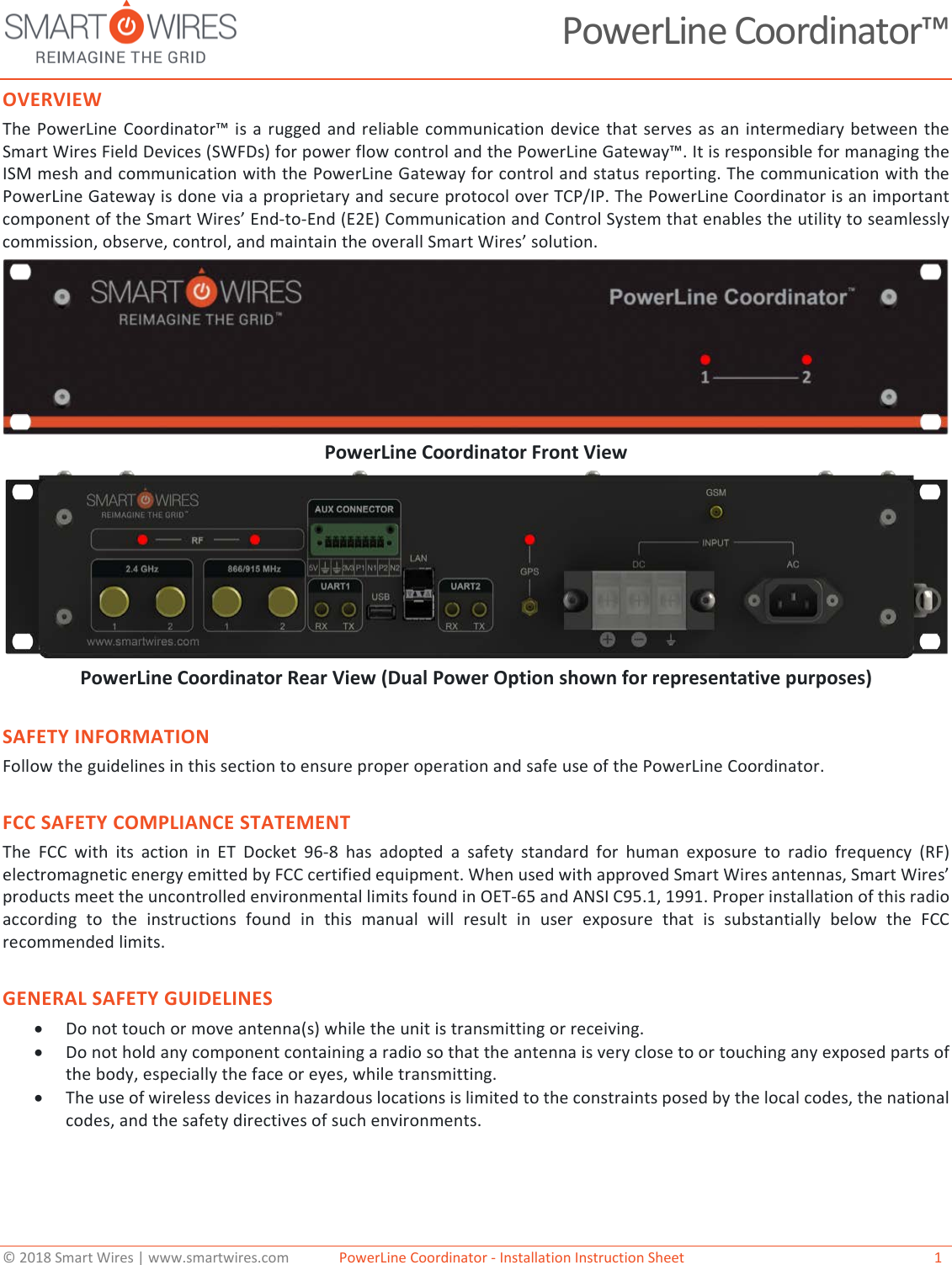
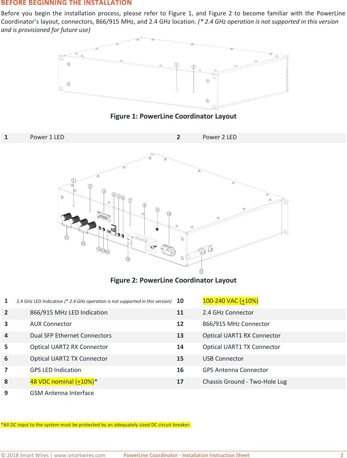
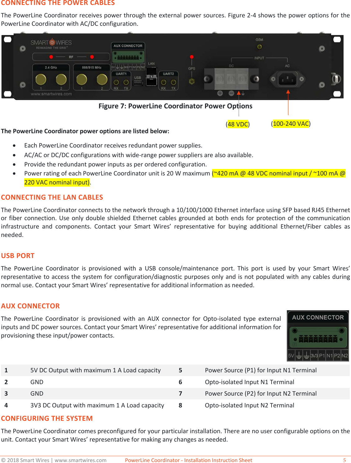
Smart Wires 01004 Power Guardian System User Manual PowerLine Coordinator Installation Manual

Smart Wires, Inc. Power Guardian System PowerLine Coordinator Installation Manual

Contents

Manual PLC

© 2018 Smart Wires | www.smartwires.com              PowerLine Coordinator - Installation Instruction Sheet   1 PowerLine Coordinator™ OVERVIEW The PowerLine Coordinator™ is a rugged and reliable communication device that serves as an intermediary between the Smart Wires Field Devices (SWFDs) for power flow control and the PowerLine Gateway™. It is responsible for managing the ISM mesh and communication with the PowerLine Gateway for control and status reporting. The communication with the PowerLine Gateway is done via a proprietary and secure protocol over TCP/IP. The PowerLine Coordinator is an important component of the Smart Wires’ End-to-End (E2E) Communication and Control System that enables the utility to seamlessly commission, observe, control, and maintain the overall Smart Wires’ solution.  PowerLine Coordinator Front View PowerLine Coordinator Rear View (Dual Power Option shown for representative purposes) SAFETY INFORMATION Follow the guidelines in this section to ensure proper operation and safe use of the PowerLine Coordinator. FCC SAFETY COMPLIANCE STATEMENT The FCC with its action in ET Docket 96-8 has adopted a safety standard for human exposure to radio frequency (RF) electromagnetic energy emitted by FCC certified equipment. When used with approved Smart Wires antennas, Smart Wires’ products meet the uncontrolled environmental limits found in OET-65 and ANSI C95.1, 1991. Proper installation of this radio according to the instructions found in this manual will result in user exposure that is substantially below the FCC recommended limits. GENERAL SAFETY GUIDELINES •Do not touch or move antenna(s) while the unit is transmitting or receiving.•Do not hold any component containing a radio so that the antenna is very close to or touching any exposed parts ofthe body, especially the face or eyes, while transmitting.•The use of wireless devices in hazardous locations is limited to the constraints posed by the local codes, the nationalcodes, and the safety directives of such environments.
© 2018 Smart Wires | www.smartwires.com              PowerLine Coordinator - Installation Instruction Sheet   2 BEFORE BEGINNING THE INSTALLATION Before you begin the installation process, please refer to Figure 1, and Figure 2 to become familiar with the PowerLine Coordinator’s layout, connectors, 866/915 MHz, and 2.4 GHz location. (* 2.4 GHz operation is not supported in this version and is provisioned for future use)Figure 1: PowerLine Coordinator Layout 1 Power 1 LED 2 Power 2 LED Figure 2: PowerLine Coordinator Layout 1       2.4 GHz LED Indication (* 2.4 GHz operation is not supported in this version) 10 100-240 VAC (+10%)2 866/915 MHz LED Indication 11 2.4 GHz Connector 3 AUX Connector 12 866/915 MHz Connector 4 Dual SFP Ethernet Connectors 13 Optical UART1 RX Connector 5 Optical UART2 RX Connector 14 Optical UART1 TX Connector 6 Optical UART2 TX Connector 15 USB Connector 7 GPS LED Indication 16 GPS Antenna Connector 8 48 VDC nominal (+10%)* 17 Chassis Ground - Two-Hole Lug 9 GSM Antenna Interface *All DC input to the system must be protected by an adequately sized DC circuit breaker.
© 2018 Smart Wires | www.smartwires.com              PowerLine Coordinator - Installation Instruction Sheet   3 DEPLOYING THE POWERLINE COORDINATORS ON YOUR NETWORK Prior to beginning the actual PowerLine Coordinator deployment, perform these tasks: •Ensure that an RF site survey has been performed.•Ensure that your network infrastructure devices are operational and properly configured.To deploy PowerLine Coordinators, follow these steps: Step 1 Obtain the PowerLine Coordinator location map created during your building site survey. Step 2 Review the PowerLine Coordinator locations and identify the specific mounting methods required for each PowerLine Coordinator location. Step 3 Mount the PowerLine Coordinator at the indicated destination using the specified mounting method. For specific mounting instructions, contact your Smart Wires’ representative. Step 4 Connect the chassis ground to a proper ground point as required by your local building code. Step 5 Mount all antennas using appropriate mounting hardware. Ensure that base of the antenna is properly secured and grounded. Use lightning arrestors for exterior mounting with additional ground connections as required by the arrestor part selected. CONNECTING THE 866/915 MHz AND 2.4 GHz ANTENNAS (*2.4Ghz not supported in this version)The PowerLine Coordinator supports a single antenna or dual diversity antennas. Two N-Type antenna connectors are there for each radio on the back of the unit for the 866/915MHz and 2.4 GHz radio for redundancy (* 2.4 GHz operation is not supported in this version and is provisioned for future use). The appropriate frequency for your specific installation is selected at the factory and is not user selectable. Depending upon the features ordered, a cellular backup option may be provisioned in your PowerLine Coordinator for redundant communication. Contact your Smart Wires’ representative for details about your system configuration. To attach your antenna or antenna cable to the PowerLine Coordinator, follow these steps: Step 1 Attach an antenna or antenna cable to the 866/915MHz, Right N-Type antenna connector on the back of the PowerLine Coordinator and hand tighten. If you are using two antennas for redundancy, attach the second antenna or antenna cable to the 866/915MHz, Left N-Type antenna connector. Step 2 Make sure antenna-mounting bracket should be properly grounded through lightning arrestor as shown in Figure 3 and Figure 4. Antenna and Lightening Arrestor The recommended antenna and lightening arrestor for use with the PowerLine Coordinator are the OMB.8912.05F21 and ALQP-NMNFB respectively. Equivalent antennas may be used, but the EIRP of the setup shall not exceed the limits imposed by local authorities having jurisdiction over the RF spectrum. Contact your Smart Wires’  representative for details and additional information.  Figure 3: Lightning Surge Arrestor
© 2018 Smart Wires | www.smartwires.com              PowerLine Coordinator - Installation Instruction Sheet   4 Figure 4: 866/915 MHz Antenna Mounting 1  OMB.8912.05F21 Antenna 5  M6 U Type Screw 2  Cover 6  M6 Washer 3  Holder 7  M6 Nut 4  N Type (F) Connector
© 2018 Smart Wires | www.smartwires.com              PowerLine Coordinator - Installation Instruction Sheet  5 CONNECTING THE POWER CABLES The PowerLine Coordinator receives power through the external power sources. Figure 2-4 shows the power options for the PowerLine Coordinator with AC/DC configuration. Figure 7: PowerLine Coordinator Power Options The PowerLine Coordinator power options are listed below: •Each PowerLine Coordinator receives redundant power supplies.•AC/AC or DC/DC configurations with wide-range power suppliers are also available.•Provide the redundant power inputs as per ordered configuration.•Power rating of each PowerLine Coordinator unit is 20 W maximum (~420 mA @ 48 VDC nominal input / ~100 mA @220 VAC nominal input).CONNECTING THE LAN CABLES The PowerLine Coordinator connects to the network through a 10/100/1000 Ethernet interface using SFP based RJ45 Ethernet or fiber connection. Use only double shielded Ethernet cables grounded at both ends for protection of the communication infrastructure and components. Contact your Smart Wires’  representative for buying additional Ethernet/Fiber cables as needed. USB PORT The PowerLine Coordinator is provisioned with a USB console/maintenance port. This port is used by your Smart Wires’ representative to access the system for configuration/diagnostic purposes only and is not populated with any cables during normal use. Contact your Smart Wires’ representative for additional information as needed. AUX CONNECTOR The PowerLine Coordinator is provisioned with an AUX connector for Opto-isolated type external inputs and DC power sources. Contact your Smart Wires’ representative for additional information for provisioning these input/power contacts.  1  5V DC Output with maximum 1 A Load capacity 5  Power Source (P1) for Input N1 Terminal 2  GND 6  Opto-isolated Input N1 Terminal 3  GND 7  Power Source (P2) for Input N2 Terminal 4  3V3 DC Output with maximum 1 A Load capacity 8  Opto-isolated Input N2 Terminal CONFIGURING THE SYSTEM The PowerLine Coordinator comes preconfigured for your particular installation. There are no user configurable options on the unit. Contact your Smart Wires’ representative for making any changes as needed.  (48 VDC)   (100-240 VAC)
© 2018 Smart Wires | www.smartwires.com              PowerLine Coordinator - Installation Instruction Sheet  6 ABOUT SMART WIRES Based in the San Francisco Bay Area, with offices in the United States, the United Kingdom, Ireland, and Australia, Smart Wires is the leader in grid optimization solutions that leverage its patented modular power flow control technology. Smart Wires’ solutions are quickly deployable, enabling utilities to react quickly and address emergency problems. This flexible technology is also easily re-deployable, providing a robust investment to solve short-duration need windows and hedge against the uncertain nature of their systems’ future needs. Driven by a world-class leadership team with extensive experience delivering innovative solutions, Smart Wires’ partners with utilities around the globe to address the unique challenges of the rapidly evolving electric system. Smart Wires’ technology was developed by utilities for utilities, led by a consortium of large U.S. utilities at the National Electric Energy Testing Research and Applications Center (NEETRAC). This core group of utilities, which included Southern Company and Tennessee Valley Authority (TVA), defined the vision for the original modular power flow control solution. PG&E, EirGrid (Ireland), Minnesota Power, Central Hudson, and Western Power (Australia) are some of the other utilities leveraging Smart Wires’ power flow control solutions.While Smart Wires strives to make the content of its marketing materials as timely and accurate as possible, Smart Wires makes no claims, promises, or guarantees about the accuracy, completeness, or adequacy of, and expressly disclaims liability for errors and omissions in, such materials. No warranty of any kind, implied, expressed, or statutory, including but not limited to the warranties of non-infringement of third party rights, title, merchantability, and fitness for a particular purpose, is given with respect to the content of these marketing materials.  © Copyright 2018, Smart Wires Inc. All rights reserved. Smart Wires Inc. 3292 Whipple Road Union City, CA 94587 Tel: (415) 800-5555 www.smartwires.com Version 18.07.09 Regulatory Compliance User Notice:FCC:This equipment has been tested and found to comply with the limits for a Class A digital device, pursuant to part 15 of the  FCC Rules. These limits are designed to provide reasonable protection against harmful interference when the equipment is operated in a commercial environment. This equipment generates, uses, and can radiate radio frequency energy and, if not installed and used in accordance with the instruction manual, may cause harmful interference to radio communications. Operation of this equipment in a residential area is likely to cause harmful interference in which case the user will be required to correct the interference at his own expense.IC:This device contains licence-exempt transmitter(s)/receiver(s) that comply with Innovation, Science and Economic Development Canada’s licence-exempt RSS(s). Operation is subject to the following two conditions:1. This device may not cause interference.2. This device must accept any interference, including interference that may cause undesired operation of the device. Innovation, Science and Economic Development Canada ICES-003 Compliance Label: CAN ICES-3(A)/NMB-3(A)L’émetteur/récepteur exempt de licence contenu dans le présent appareil est conforme aux CNR d’Innovation, Sciences etDéveloppement économique Canada applicables aux appareils radio exempts de licence. L’exploitation est autorisée auxdeux conditions suivantes :1. L’appareil ne doit pas produire de brouillage;2. L’appareil doit accepter tout brouillage radioélectrique subi, même si le brouillage est susceptible d’encompromettre le fonctionnement.Étiquette de conformité à la NMB-003 d’Innovation, Sciences et Développement économique Canada : CAN ICES-3(A)/-3(A) To comply with RF exposure limits established in the ANSI C95.1 standard, the distance between the antenna or antennas and the user should not be less than 20 cm for USA and CanadaThis product does not contain any user serviceable components. Any unauthorized product changes or modifications will invalidate warranty and all applicable regulatory certifications and approvals, including authority to operate this device. This device complies with Part 15 of the FCC Rules. Operation is subject to the following two conditions: (1) this device may not cause harmful interference, and (2) this device must accept any interference received, including interference that may cause undesired operation. Canada – Industry Canada (IC)This device complies with Industry Canada RSS-247 and license-exempt RSS standard(s). Operation is subject to the following two conditions: (1) this device may not cause interference, and (2) this device must accept any interference, including interference that may cause undesired operation of the device. Ce dispositif est conforme à lanorme CNR-247 d'Industrie Canada applicable aux appareils radio exempts de licence. Son fonctionnement est sujet aux deux conditions suivantes: (1) le dispositif ne doit pas produire de brouillage préjudiciable, et (2) ce dispositif doit acceptertout brouillage reçu, y compris un brouillag e susceptible de provoquer un fonctionnement indésirable.

Navigation menu