Smart Wires 01005 SmartBypass User Manual SmartInterface
Smart Wires, Inc. SmartBypass SmartInterface
Manual

D000587 Rev B
SmartBypassTM User Guide
© 2019 Smart Wires Inc. The information and methodologies outlined herein and their expression in this
document is copyrighted with all rights reserved. Copying or distributing it without prior written permission
is strictly prohibited.
List of Revisions
Revision
ECO
Date
Action
Pages Modified
A ECO-000575 01/29/2019 Initial Release All

D000587 SmartBypass User Guide
Revision A
© 2019 Smart Wires | www.smartwires.com Page 2 of 7
Table of Contents
1 Scope-------------------------------------------------------------------------------------------------------------------------------------------- 3
2 Purpose ---------------------------------------------------------------------------------------------------------------------------------------- 3
3 Abbreviations -------------------------------------------------------------------------------------------------------------------------------- 3
4 General Product Overview --------------------------------------------------------------------------------------------------------------- 3
5 Electrical Operation of Single Module ------------------------------------------------------------------------------------------------ 4
5.1 Enclosure ------------------------------------------------------------------------------------------------------------------------------ 4
5.2 Inductors ------------------------------------------------------------------------------------------------------------------------------ 4
5.3 Normally Closed Contactor------------------------------------------------------------------------------------------------------- 4
5.4 Silicon Controlled Rectifiers ------------------------------------------------------------------------------------------------------ 4
5.5 Metal Oxide Varistor --------------------------------------------------------------------------------------------------------------- 4
6 SmartBypass Control ----------------------------------------------------------------------------------------------------------------------- 5
7 Product Components----------------------------------------------------------------------------------------------------------------------- 6
8 Wireless Communication ----------------------------------------------------------------------------------------------------------------- 6
9 Regulatory Compliance User Notice: -------------------------------------------------------------------------------------------------- 7
List of Tables
Table 2: Abbreviations ................................................................................................................................................... 3
Table 3: SmartBypass Models and Specifications .......................................................................................................... 5
List of Figures
Figure 4-1: SmartBypass with Mounting Bracket and Corona Rings ----------------------------------------------------------------- 3
Figure 5-1: SmartBypass System Diagram -------------------------------------------------------------------------------------------------- 5
Figure 7-1: Individual Components of the SmartBypass -------------------------------------------------------------------------------- 6
D000587 SmartBypass User Guide
Revision A
© 2019 Smart Wires | www.smartwires.com Page 3 of 7
Preface
1 Scope
This user guide applies to the operation and purpose of the SmartBypass. It also provides the FCC compliance
information.
2 Purpose
The purpose of this document is describe to the user the purpose, components, operation and communication
method of the SmartBypass.
3 Abbreviations
Term Definition
A RMS Amperes Root Mean Squared
SCR Silicon Controlled Rectifier
MOV Metal Oxide Varistor
NC Normally Closed
ISM Industrial, Scientific, and Medical Radio Band
Table 1: Abbreviations
4 General Product Overview
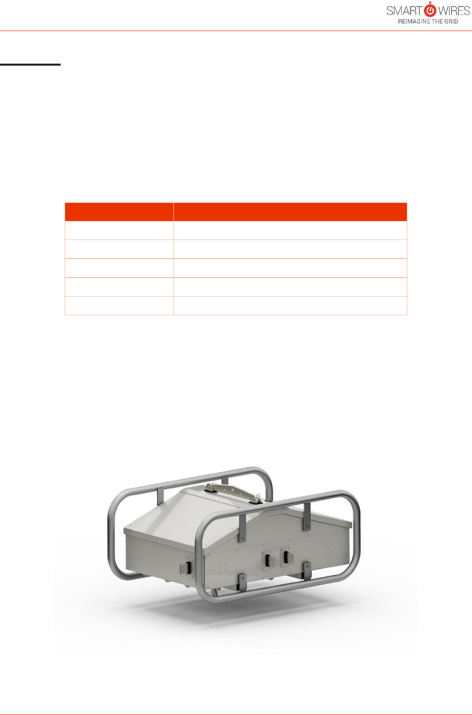
Smart Wires’ SmartBypass technology is designed to protect other Smart Wires series compensation devices. The
SmartBypass does this by automatically activating switches to carry the transmission line current during line faults
or when operators desire to manually bypass the series compensation. The SmartBypass technology builds on the
protection used in other Smart Wires products, like the Power Guardian 390 which has internal protection on the
secondary side of its injection transformer. The SmartBypass is installed on a single-phase basis, meaning that for
most transmission deployments, there will be an equal number of units per phase.
Figure 4-1: SmartBypass with Mounting Bracket and Corona Rings

D000587 SmartBypass User Guide
Revision A
© 2019 Smart Wires | www.smartwires.com Page 4 of 7
5 Electrical Operation of Single Module
The SmartBypass comes in several different models as shown in Table 2. The SmartBypass can operate at line
currents of thousands of amps during normal bypass operation and withstand different fault current levels
depending on the model. The SmartBypass models are differentiated by continuous current rating and maximum
fault current rating. For example, the SmartBypass 4000-63 is rated for continuous line currents up to 4000 A RMS
and fault currents of up to 63 kA RMS for 1 second.
The SmartBypass provides telemetry when operating in monitoring mode or injection mode. The SmartBypass
operates to protect the power electronic components within Smart Wires series compensation devices by
operating when the devices are switched in series with the line, when a fault occurs on the line and when the
devices are switched out of series with the line. The SmartBypass can bypass Smart Wires series compensation
devices within in 1 msec of the inception of a fault, thus ensuring the protection of internal power electronics of
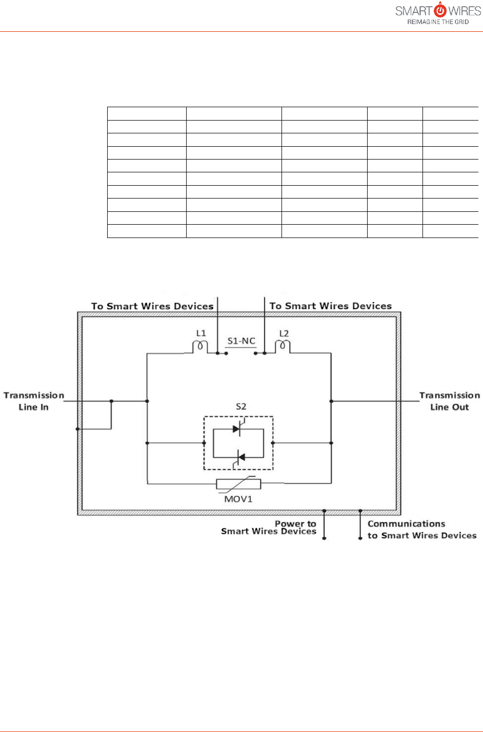
the devices. Figure 5-1 illustrates the basic electrical configuration of the SmartBypass.
5.1 Enclosure
The enclosure of the SmartBypass is connected to the transmission line at one terminal, this ensures the enclosure
is at line potential. All other terminals and components are insulated from the enclosure.
5.2 Inductors
Each SmartBypass contains two small inductors, represented by L1 and L2, one on either side of the normally
closed vacuum series link, S1. The inductors ensure the voltage across S1 is close to 0 V when S1 opens and closes,
extending the lifetime of this component.
5.3 Normally Closed (NC) Contactor
The normally closed contactor, represented by S1-NC, carries the current when the Smart Wires series
compensation devices are bypassed under normal conditions. S1 is what determines the continuous current rating
of the SmartBypass, S1 can carry either 2000 A RMS continuously or 4000 A RMS continuously.
5.4 Silicon Controlled Rectifiers
Each SmartBypass contains one or more pairs of anti-parallel silicon-controlled rectifier (SCR), shown as S2 in figure
2. The SCRs carry the line current in the case of a fault or when S1 operates to switch in or switch out the Smart
Wires series compensation devices.
5.5 Metal Oxide Varistor
The SmartBypass is equipped with a metal oxide varistor, MOV1 in Figure5-1. MOV1 protects the internal
components of the SmartBypass from high current events such as lightning strikes.
D000587 SmartBypass User Guide
Revision A
© 2019 Smart Wires | www.smartwires.com Page 5 of 7
Model
Continuous
Current Rating
(A RMS)
Maximum 2-Hour
Emergency Current
(A RMS)
Fault Current
Rating (kA RMS
for 1 s)
Peak Fault Current
(kA)
60 Hz
50 Hz
SmartBypass 2000-63
2000
2160
63.0
164.0
158.0
SmartBypass 2000-50
2000
2160
50.4
131.0
126.0
SmartBypass 2000-38
2000
2160
38.0
98.8
95.0
SmartBypass 2000-25
2000
2160
25.2
65.0
63.0
SmartBypass 2000-12
2000
2160
12.6
32.0
31.5
SmartBypass 4000-63
4000
4320
63.0
164.0
158.0
SmartBypass 4000-50
4000
4320
50.4
131.0
126.0
SmartBypass 4000-38
4000
4320
38.0
98.8
95.0
SmartBypass 4000-25
4000
4320
25.2
65.0
63.0
SmartBypass 4000-12
4000
4320
12.6
32.0
31.5
Table 2: SmartBypass Models and Specifications
Figure 5-1: SmartBypass System Diagram
6 SmartBypass Control
The SmartBypass has 2 distinct modes of operation, the performance and operation of the modes is described
below.
1. Monitoring Mode – The normally closed contactor S1 is closed. The SmartBypass bypasses the Smart
Wires series compensation devices across its terminals so no reactance is injected. The SmartBypass can
transmit telemetry data in this mode. When the SmartBypass senses a line current which exceeds its rated
tolerance, it automatically bypasses the Smart Wires series compensation devices with fast-acting
antiparallel SCR switches (S2), entering monitoring mode within 1 millisecond.
D000587 SmartBypass User Guide
Revision A
© 2019 Smart Wires | www.smartwires.com Page 6 of 7
2. Injection Mode – The normally closed contactor S1 is open. SmartBypass allows the Smart Wires series
compensation devices to inject their reactance across its terminals in series with the line.
7 Product Components
The individual components of the SmartBypass are shown in Figure 7-1.
Figure 7-1: Individual Components of the SmartBypass
A – Protection Circuitry – the Silicon Controlled Rectifiers (SCRs) are housed longitudinally along the interior floor
of the unit.
B – Yoke Plate – this plate is the fixture point for insulators supporting the unit from above.
C – NEMA Pads – these are the electrical connection points for the unit.
D – Corona Rings – surround both latitudinal sides of the device to prevent corona at high voltages.
E – Normally Closed Contactor – the normally closed contactor is housed across the top of the inside of the
enclosure parallel to the yoke plate.
8 Wireless Communication
The SmartBypass has the capability to communicate over a secure wireless Industrial, Scientific and Medical (ISM)
band. The ISM Secure Wireless Mesh is the communication network protocol based on Radio Frequency wireless
communication for between ground-based equipment and the SmartBypass. The SmartBypass support the 900
MHz band in the US. The SmartBypass uses a frequency-hopping spread-spectrum solution. It does not occupy a
single user-selectable-channel like, for example, WiFi does.
A
B
C
D
E

D000587 SmartBypass User Guide
Revision A
© 2019 Smart Wires | www.smartwires.com Page 7 of 7
9 Regulatory Compliance User Notice:
FCC:
This equipment has been tested and found to comply with the limits for a Class A digital device,
pursuant to part 15 of the FCC Rules. These limits are designed to provide reasonable protection
against harmful interference when the equipment is operated in a commercial environment.
This equipment generates, uses, and can radiate radio frequency energy and, if not installed and used in
accordance with the instruction manual may cause harmful interference to radio communications.
Operation of this equipment in a residential area is likely to cause harmful interference in which
case the user will be required to correct the interference at his own expense.
CAUTION: Changes or modifications not expressly approved by the party responsible for compliance could void the
user's authority to operate the equipment.
END OF DOCUMENT