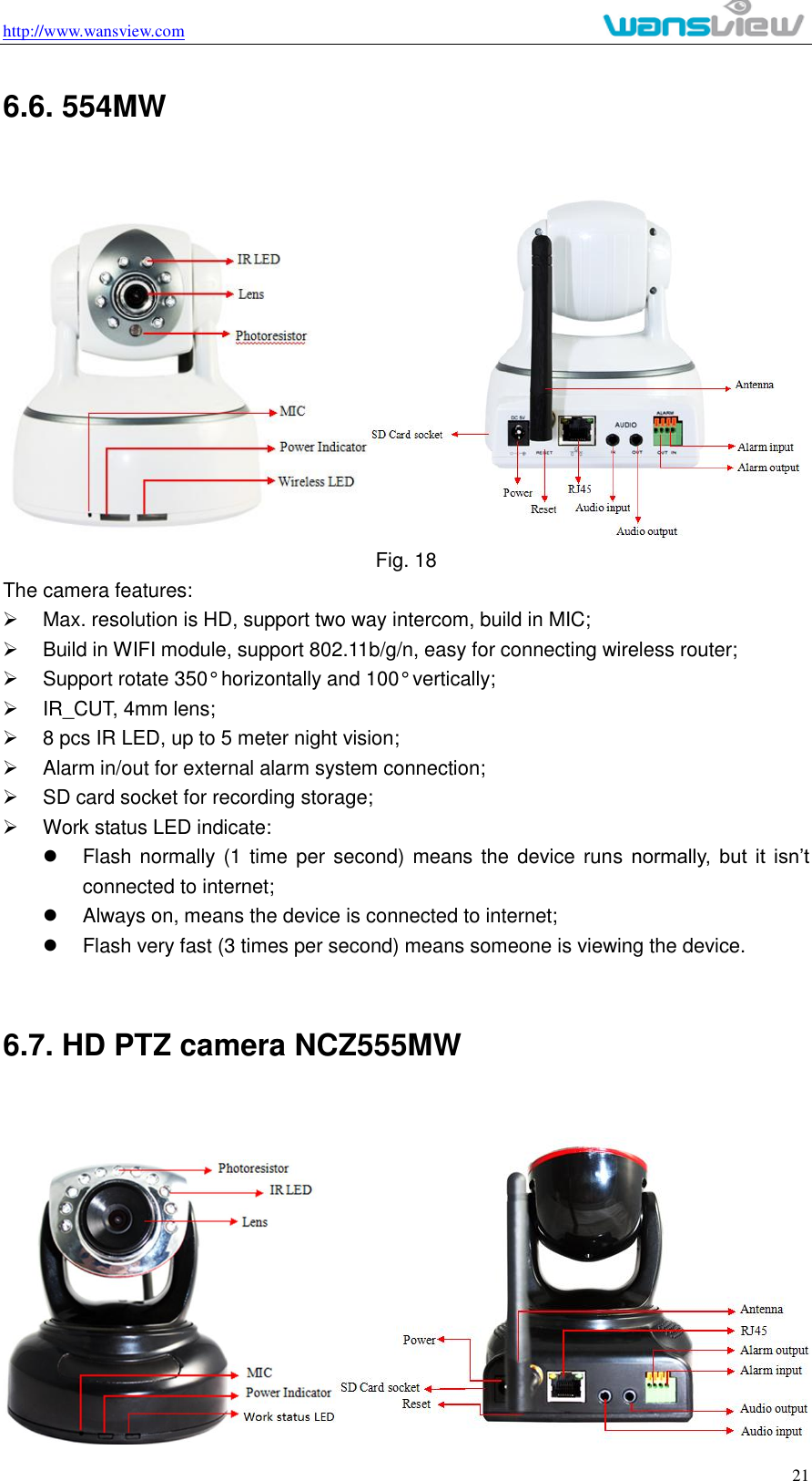
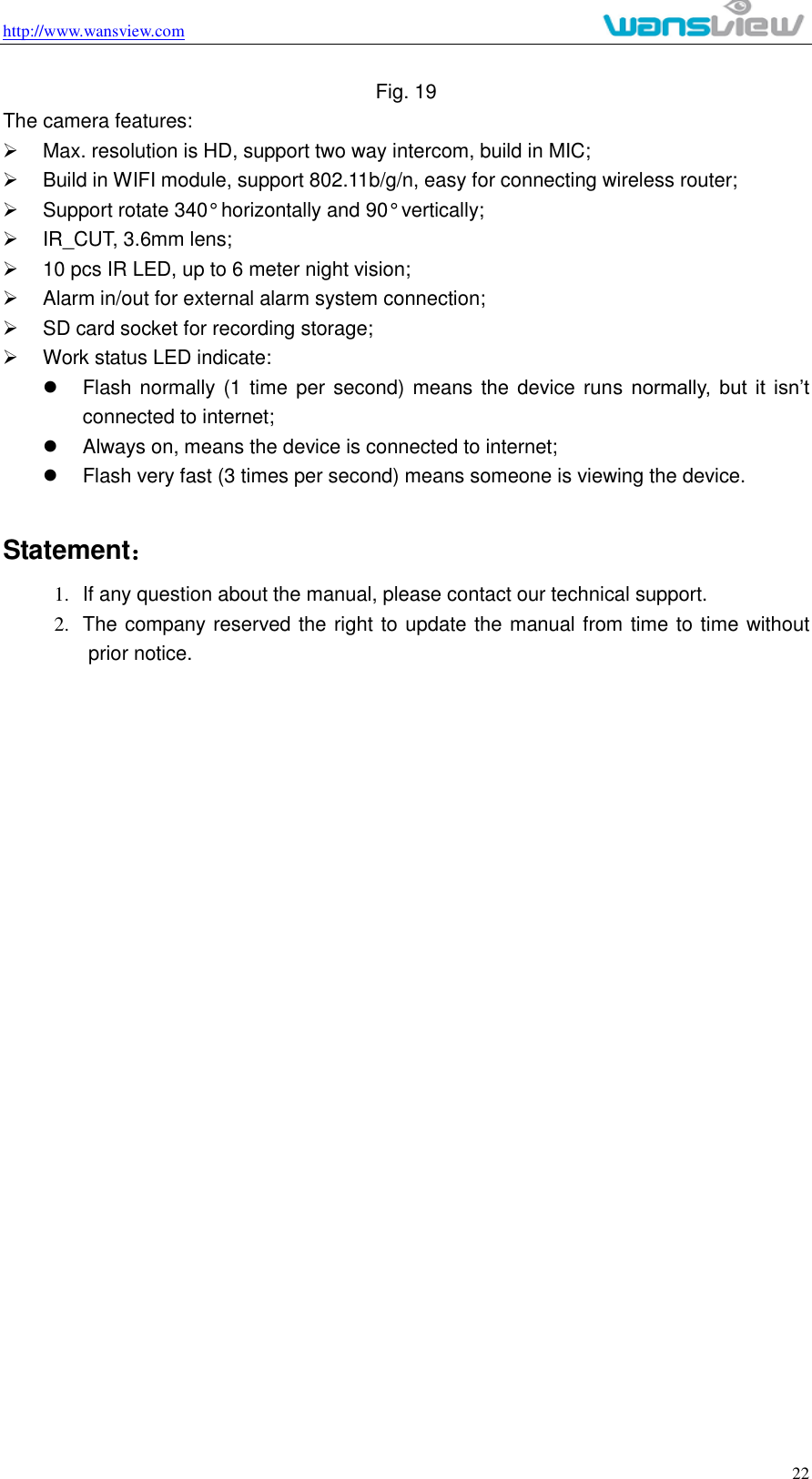
Smart eye Digital Electronics HYIPC-554MW IP Camera User Manual
Shenzhen Smart-eye Digital Electronics Co.,Ltd IP Camera Users Manual
UserManual.wiki
>
Smart eye Digital Electronics
>
HYIPC 554MW User Manual
user manual
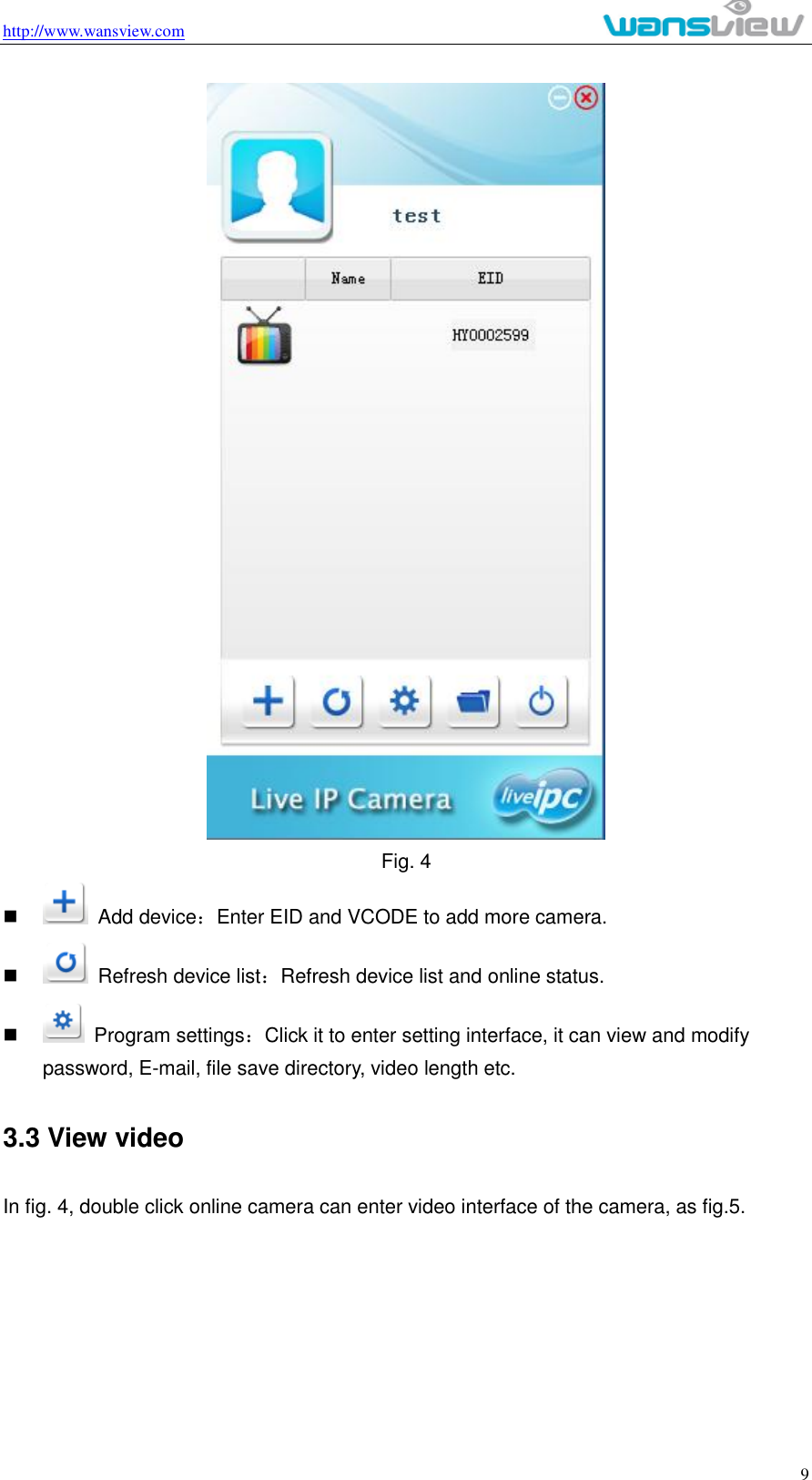
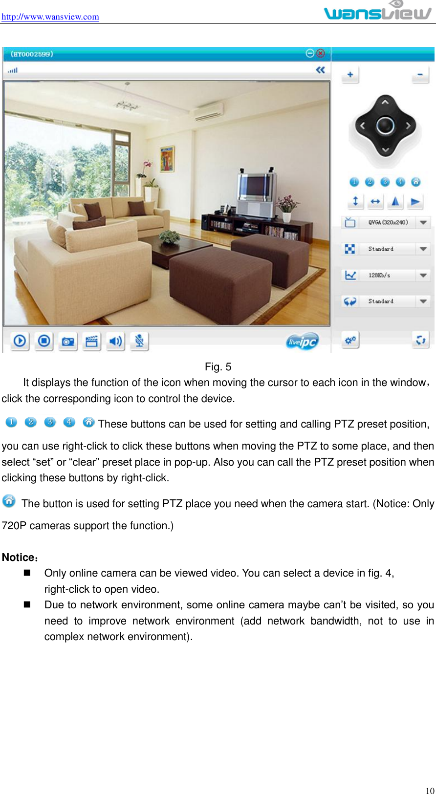
Navigation menu
Upload a User Manual
Namespaces
Wiki Guide
HTML
PDF
Info
Views
User Manual
Discussion / Help
Navigation