SmartBridges NEXUS2 802.11a/b/g MiniPCI WLAN Card User Manual
SmartBridges Pte Ltd 802.11a/b/g MiniPCI WLAN Card Users Manual
Users Manual
FCC ID PWG NEXUS2 1
Installation Manual
smartBridges model SB3001
IEEE 802.11a,b,g MiniPCI WLAN Card
Installation Manual
Version 0.21
FCC ID PWG NEXUS2 2
Installation Manual
Table of Contents
1-INTRODUCTION.......................................................................................3
2-INSTALLATION PROCEDURE…............................................................3
2.1 NEXUS 3010 Back Haul Device for Out door… ................................3
2.2 INSTALLING THE MINIPCI CARD SB 3001 INTO NEXUS 3010.. .3
2.3 NEXUS 3010 software ……………………...........................................4
2.4 User Manual for NEXUS 3010 ……………………..………………..5
2.5 User Manual for NEXUS 3210 ……………………………………….. 9
2.6 User Manual for NEXUS 3410 ………………………………………. 10
2.7 Mounting the unit..………………………………………………….. 11
2.8 Wireless LAN Installation and Authorization ...…………………...... 14
2.9 Label Fixing ………………………………………………………….14
3-REGULATORY INFORMATION................................................................15
3.1 FCC INFORMATION TO USER…........................................................15
3.2 FCC GUIDELINES FOR HUMAN EXPOSURE....................................15
3.3 FCC ELECTRONIC EMISSION NOTICES...........................................15
3.4 FCC RADIO FREQUENCY INTERFERENCE STATEMENT.............16
3.5 EXPORT RESTRICTIONS.....................................................................16
4-TECHNICAL SPECIFICATIONS................................................................17
FCC ID PWG NEXUS2 3
Installation Manual
1. Introduction
The smartBridges SB3001 is a complete wirelessLAN high speed Network Interface
Card (NIC) used for Point to Point and Point to Multi Point Links with external
antennas.Developed by modifying GlobespanVirata ISL39200M WLAN NIC, it
conforms to the IEEE 802.11a,b,g protocol , works in point to point and point to
multi point mode and operates in the 2412-2483.5,5250-5350 MHz frequency band. The
device shall not be used in any application other than Point to Point and Point to multi
Point modes.
1. The module has Radio PCB and Booster PCB glued together inseparably with
epoxy based potting compound . Any attempt to separate the PCB’s will
destroy both the PCB’s irrepairably . Booster is an amplifier which keeps
intact spectral mask and offers higher receiver sensitivity for the radio. This
platform is used to enhance Nexus features.
2. Antennas qualified with the device are 31dBi Parabolic Dish 5.3 GHz , 31.5 dBi
Parabolic Dish 5.25~5.7GHz , 29dBi Parabolic grid , 29 dBi Panel for 5.25 ~
5.35 GHz band and 5.25 ~ 5.75 GHz bands . For 2.412 ~ 2.485 GHz band
following antennas are qualified : 24 dBi Parabolic Grid , 17 dBi Vertically
Polarised Sector antenna , 16.5 dBi Horizontally Polarised sector antenna , 12 dBi
Omni antenna . Other antennas in the same family but with lower gain are
allowed for use with the device.
• Fully compliant with the IEEE 802.11a ,b, g WLAN standards for Point to point and
Point to Multi Point links
• FCC Certified Under Part 15 (pending) to Operate in the 5250~5350 , 2412 ~ 2483.5
MHz Bands
• Support for 54, 48, 36, 24, 18, 12, 9, and 6 Mbps OFDM
• Driver Supports Microsoft Windows ® 98/SE, ME, XP and 2000 (SR1)
2. Installation Procedure
SB 3001 has to be installed inside smartBridges NEXUS 3010 out door specified
back haul device or NEXUS 3020 Access Points or NEXUS 3040 Client Devices .
2.1 NEXUS 3010, BackHaul , 3020 , Access Point , 3040 , Client device for
outdoor application
NEXUS 3010 is a Back Haul Point to Point link for carrying high data traffic
. It uses Intel IXP 425 BCT a powerful processor to run the application and
provide high security . It provides two Ethernet ports for connection to network
devices or PC . Antenna is connected to the NEXUS unit .
NEXUS 3020 is a wireless Access Point for high data traffic . It uses the same
hardware as NEXUS 3010 and provides point to multi Point Access .
NEXUS 3040 is a wireless Client device for high speed internet access . It
works with NEXUS 3020 as Access Point . Many clients can be connected to an
Access Point .
NEXUS 3010 , 3020 , 3040 are meant for out door applications . The device has
to be mounted on Tower or roof top along with the antenna . It has all
mounting hardware for this purpose .
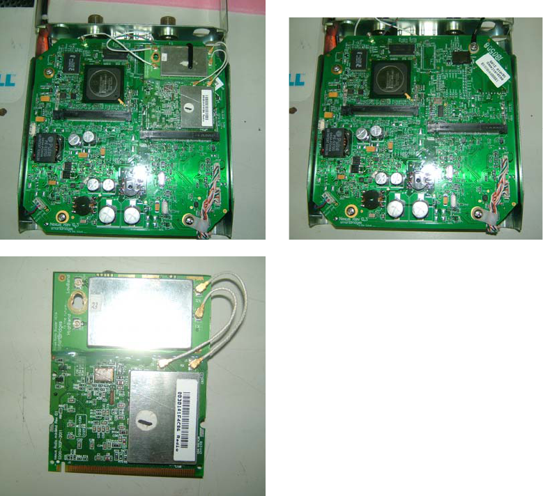
2.2 Installing SB 3001 into NEXUS 3010/ 3020/ 3040
The module SB 3001 is normally installed into NEXUS 3010/ 3020/ 3040 in
the factory at the time of manufacturing . NEXUS 3010/ 3210/ 3410 has mini
PCI connector ( socket ). The Radio module SB 3001 can directly fit into the
NEXUS unit and is fixed by screws to the mounting pillars shown .
FCC ID PWG NEXUS2 4
Installation Manual
IXP 425 communicates with the Radio module and routes the data signals
with necessary mini PCI format and controlling software . The units are run by
software resident in the memory IC’s . SB 3010 can communicate to another SB
3010 only . The second device can be connected only when its MAC number is
written into the first device . Channel blocking is provided by the software
control which does not allow the user to select un authorized channels .
SB 3210 is an Access Point which can connect to many SB 3410 client
devices .
2.3 NEXUS 3010 Software
NEXUS 3010 runs on its own software and does not require external PC
software . PC provides Graphic User Interface and displays all controls and
allows the user to configure the units . One unit is configured as Root device
and another is configured as Remote Client . Root is master device and Client
is slave in configuration . This configuration is required for networking
purposes .
Channel setting and output power control and client authentication are main
functions of master . Slave gets wireless signals , decodes them and outputs
them through Ethernet connector . The access points and other network devices
are connected through the Ethernet link . Master normally connects to the
internet back bone .
FCC ID PWG NEXUS2 5
Installation Manual
2.4 User Manual NEXUS 3010
SB 3001 module which is the main Transmitting and Receiving module
inside NEXUS 3010 does not have independent user interface functionality .
User controls the Radio module through NEXUS
3010 operating Instructions . The Instructions run as below .
Activating the Link
It is recommended that you activate and configure the NEXUS 3010 link on your desktop
prior to mounting the units in the field. Associating the units in advance will facilitate
antenna alignment and simplify the overall installation procedure. Below are instructions
on how to perform a basic association to allow antenna alignment.
By default, one unit will operate in Root Bridge Mode and the other will operate in
Remote Client Bridge Mode. Follow these steps to configure the first unit for Root
Bridge Mode:
First Unit Setup
Note The default IP Address of NEXUS 3010 units is 192.168.0.205 and the default IP
Mask is 255.255.255.0. The PC must be on the same subnet as the unit to access
it (e.g. 192.168.0.10).
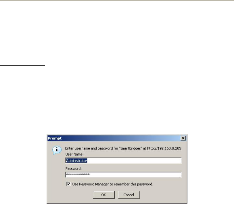
Step 1 Log into the NEXUS unit by typing ‘http://192.168.0.205’ in your web
browser window (Figure 4-1). Enter User Name: Administrator and Password:
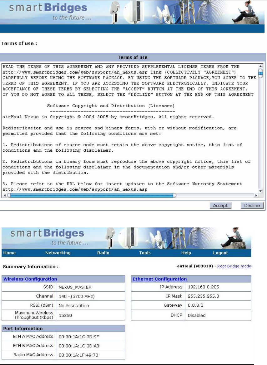
smartBridges. You will be directed to the ‘License Agreement’ page (Figure 4-
2). Click on ‘Accept’ to proceed to the ‘Summary Information’ page (Figure 4-
3).
Figure2- 4-1 Step 1: Log into airHaul unit
FCC ID PWG NEXUS2 6
Installation Manual
Figure2-4-2 Step 1: License Agreement Page
Figure 2-4-3 Step 1: Root Bridge Summary Information Page
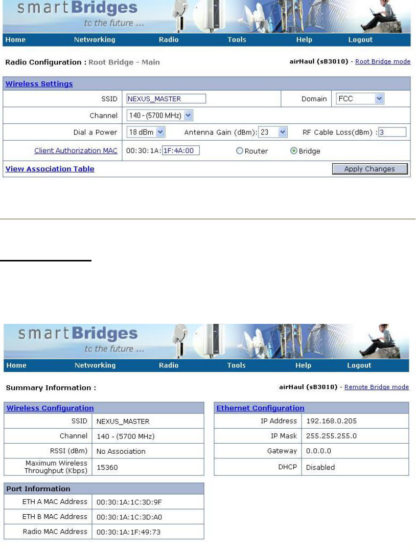
Step 2 From the ‘Radio’ drop-down menu, select ‘Main – Root Mode’ and the Radio
Configuration page will be displayed as shown in Figure 4-4. Enter the SSID of
FCC ID PWG NEXUS2 7
Installation Manual
the unit. Select the operating Domain and Channel. Enter the MAC address of
the second unit’s radio card and designate it as a Bridge. Click ‘Apply Changes’.
Figure 2-4-4 Step 2: Root Bridge Wireless Configurations
Follow these instructions to configure the second unit for Remote Client Bridge Mode:
Second Unit Setup
Step 1 After login to the second unit, click on ‘Ethernet Configuration” and give the
unit a unique IP Address on the same IP subnet (e.g. 192.168.0.2) as the first unit
and then click ‘Apply Changes’.
Figure 2-4-5 Step 1: Second Unit Ethernet Configuration
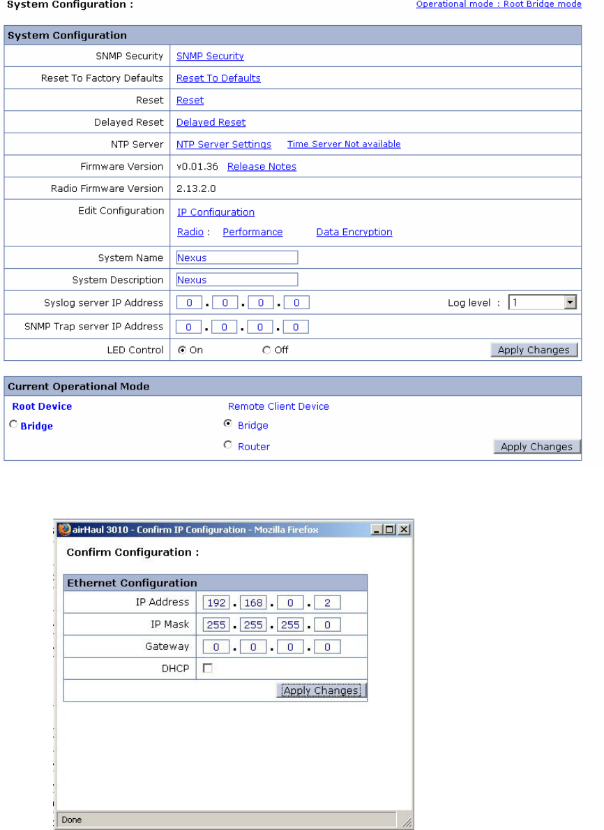
Step 2 From the Summary Information page, click on “Operational Mode” (in the top
right hand corner) to redirect to System Configuration page as shown in Figure
4-6. Select the Bridge radio button under Remote Client Device and Click
FCC ID PWG NEXUS2 8
Installation Manual
‘Apply Changes’ to change the operational mode to Remote Client Bridge mode.
A ‘Confirm Ethernet Configuration’ window pop-up will be displayed.
Figure 2-4-6 Step 2: Change Operational Mode to Remote Client Bridge mode
Step 3 Click Apply Changes in the ‘Confirm Ethernet Configuration’ pop-up window
FCC ID PWG NEXUS2 9
Installation Manual
Figure 2-4-7 Step 3: Confirm Ethernet Configuration pop-up window
Step 4 From the ‘Radio’ drop-down menu, click on ‘Main – Remote Client Bridge
Mode’ and the Radio Configuration page will be displayed as shown in Figure 4-
8. Enter the SSID, MAC address and Channel of the first unit. Click ‘Apply
Changes’. The units will attempt to associate.
Note Clicking on ‘Status’ will display further details on the association.
Figure 2-4-8 Step 4: Configuring Remote Client Bridge Wireless Settings
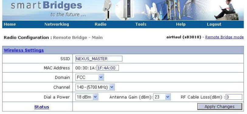
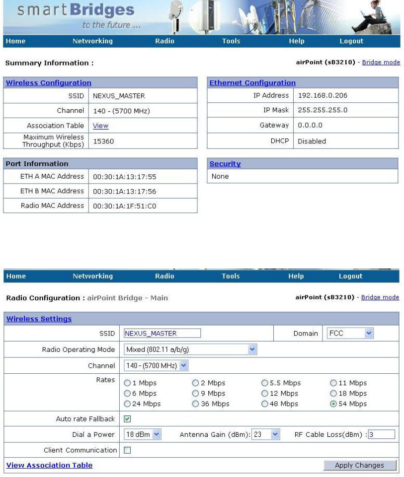
2.5 User Manual NEXUS 3210
Note The default IP Address of NEXUS 3210 unit is 192.168.0.206 and the
default IP Mask is 255.255.255.0. The PC must be on the same subnet as the unit
to access it (e.g. 192.168.0.10).
Follow step 1 of Nexus 3010 User Manual in logging into the unit. The web
browser will appear as shown below:
FCC ID PWG NEXUS2 10
Installation Manual
To choose the desired channel to operate, go to Radio and the browser will appear
as shown below:
To ensure association with a Nexus 3410, check whether the units have identical
SSIDs.
Wait for the unit to show an Associated status.
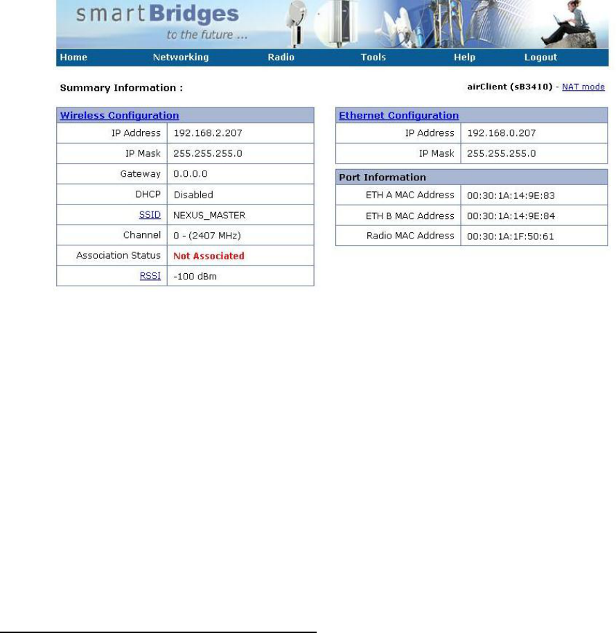
2.6 User Manual NEXUS 3410
Note The default IP Address of NEXUS 3410 unit is 192.168.0.207 and the
default IP Mask is 255.255.255.0. The PC must be on the same subnet as the unit
to access it (e.g. 192.168.0.10).
Follow step 1 of Nexus 3010 User Manual in logging into the unit. The web
browser will appear as shown
FCC ID PWG NEXUS2 11
Installation Manual
below:
To ensure association with a Nexus 3210, check whether the units have identical
SSIDs. Nexus 3410 will automatically follow the channel of the access point it is
associated to.
Wait for the unit to show an Associated status.
2.7 Mounting the Unit
This section describes how to mount the NEXUS and position the antenna. It contains the
following sections:
• Choosing a Mounting Location and Site Survey
• Assembling the Mounting Hardware
• Mounting the NEXUS
Choosing a Mounting Location and Site Survey
Every RF application is a unique installation. Before installing, you should perform a site
survey to determine the optimum use of wireless networking components and to
maximize range, coverage, and network performance.
Choosing a good mounting location for the NEXUS is important because it affects the
reliability of the wireless link and maximum data rates it can support. The most important
considerations are link length and clearance from obstacles.
The following operating and environmental conditions should be taken into account when
performing a site survey:
• Data rates—Sensitivity and range are inversely proportional to data bit rates. The
maximum radio range is achieved at the lowest workable data rate. A decrease in
receiver sensitivity occurs as the radio data increases.

FCC ID PWG NEXUS2 12
Installation Manual
• Antenna type and placement—Proper antenna configuration is a critical factor in
maximizing radio range. As a general rule, antenna height helps to reach longer
distances to avoid obstruction. However, do not place the antenna higher than
necessary, because the extra height also increases potential interference from
other unlicensed radio systems. Do not install the airHaul Nexus on a TV or
Radio receiving mast or within proximity of the same.
• Physical environment—Clear or open areas provide better radio range than closed
or filled areas.
• Obstructions—Physical obstructions such as buildings, trees, or hills can hinder
performance of wireless devices. Avoid locating the devices in a location where
there is an obstruction between the sending and receiving antennas.
Link Distance
In an environment without obstacles in the signal path, the maximum link distance
depends primarily on the type of antennas and the free space path loss. Make sure your
proposed mounting site is within range of the remote antenna. The NEXUS units have a
built-in Link Analysis Calculator to help you estimate the range for your specific
installation.
Antenna Polarization
The antennas radiate and receive polarized radio signals. Polarization helps reduce
interference because the antenna tends to reject cross-polarized signals from other
sources. Therefore, you can solve some interference problems by changing the antenna
polarization. For the link to operate correctly, two antennas at each end of the link must
always be set for the same polarization, either vertical or horizontal. The NEXUS
mounting hardware accommodates either vertical or horizontal antenna polarization.
Signal Path Clearance (Fresnel Zone)
A radio beam travels from one antenna to another in a straight line. Therefore, the path
between the antennas must be free of major obstacles. The effects of obstacles and
terrain, both along and near the path, have a significant bearing on the propagation of
radio signals and can cause both interference and signal cancellation.
When choosing a site, consider the effects of the following common obstacles:
• Trees and large plants - A tree directly in the path can totally block the signal.
With clearance above the trees there are usually no secondary effects, but you
should allow for future tree growth.
• Man-made obstacles - A large round container such as a gas storage reservoir or
water tower that is partially in the path causes some blocking. These obstacles
may also reflect some energy, which can interfere with other receivers. Square or
rectangular objects in or near the path have rectangular surfaces that can block
and diffract signals over and around them.
• Earth surface - The earth surface also interferes with signals if the antenna is
mounted too low. Mount the antenna just high enough to allow adequate
clearance from the ground. Placing the antennas too high makes it susceptible to
interference from other systems.
FCC ID PWG NEXUS2 13
Installation Manual
For tower installations, you may need to climb the tower to verify a clear path to the other
site. If trees are in the line of signal propagation, leave extra clearance above them for
future growth into the signal path.
Table 5-1 (below) can be used as a guide to determine the clearance to leave around the
signal path. Install the bridge or external antenna where obstacles along the propagation
path, including the ground, are no closer than these values.
Total Path
Length Km
(Miles)
Clearance Radius Around
Signal Path Meters (Feet)
2.4 GHz
Clearance Radius Around
Signal Path Meters (Feet)
4.9 GHz to 5.8 GHz
6 (4) 8.4 (27.6) 5.4 (17.9)
10 (6) 10.3 (33.8) 6.7 (22.0)
13 (8) 11.9 (39.1) 7.7 (25.4)
16 (10) 13.3 (43.7) 8.6 (28.4)
20 (12) 14.5 (47.9) 9.4 (31.1)
Table 5-1 Fresnel Zone Clearance Guidelines for Frequencies
How to Mount the NEXUS
This section describes the mounting procedures for rooftop, mast, and tower installations.
Personnel installing the NEXUS must understand wireless techniques, antenna alignment
and adjustment, and grounding methods. The unit is shipped with mounting hardware that
accommodates tower, mast, or rooftop installations.
5
5
1

FCC ID PWG NEXUS2 14
Installation Manual
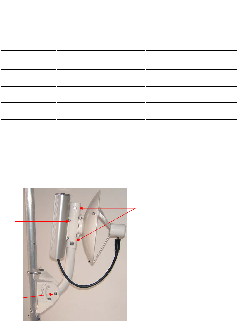
Figure2-4-9 Tower and Wall Mounting
The unit is shipped with a mounting bracket that is suitable to be attached to towers. To
mount the NEXUS on a pole, follow these steps:
Step 1 Attach the NEXUS unit to the square plate on the mounting bracket with the
supplied bolts.
Step 2 Find a suitable mounting location on the tower or wall. (If required, drill holes on
the wall corresponding to the mounting bracket holes.)
Step 3 Hoist the entire assembly to the mounting location.
Step 4 Attach the mounting arm assembly to the wall or to the tower pole using the
supplied U bolts, which fit 1.25 to 1.75 inch poles.
Step 5 Loosen the screws and adjust the vertical and horizontal alignment one at a time
to point towards the remote NEXUS unit.
Note Factory assembled smartBridges antennas are vertically polarized. Be sure to
mount the unit so that the antenna polarization matches the remote antenna
polarization. If it does not, remove the four bolts, rotate the parabolic dish 90
degrees and reattach.
2.8 Wireless LAN installation guide lines and Authorization for use
Installation and use of this Wireless LAN device must be in strict accordance with the
instructions included in the user documentation provided with the product. Any changes
or modifications made to this device that are not expressly approved by smartBridges
may void the user’s authority to operate the equipment. smartBridges is not responsible
for any radio or television interference caused by unauthorized modification of this
device, or the substitution or attachment of connecting cables and equipment other than
specified. It is the responsibility of the user to correct any interference caused by such
unauthorized modification, substitution or attachment. smartBridges and its authorized
resellers or distributors will assume no liability for any damage or violation of
government regulations arising from failing to comply with these guidelines.
The use of Wireless LAN devices may be restricted in some situations or environments
for example:
* On board of airplanes, or
* In an explosive environment, or
* In case the interference risk to other devices or services is perceived or
identified as harmful.
In case the policy regarding the use of Wireless LAN devices in specific organizations or
environments (e.g. airports, hospitals, chemical/oil/gas industrial plants, private buildings
etc.) is not clear, please first verify authorization to use these devices prior to operating
the equipment.
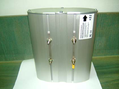
2.9 Label fixing
The installer who is installing the SB 3001 module inside Nexus 3010 should
FCC ID PWG NEXUS2 15
Installation Manual
paste FCC label “ Contains FCC ID PWG NEXUS2” at the backside of the unit as in
picture below.
3-Regulatory information
3.1 FCC Information to User
This product does not contain any user serviceable components and is to be used with
approved antennas only. Any product changes or modifications will invalidate all
applicable regulatory certifications and approvals
3.2 FCC Guidelines for Human Exposure
In order to comply with RF exposure limits, the user is advised to maintain a distance of
at least 70 cm from the antenna of this device while it is in use. The antenna is external
to the device . Antennas qualified are 31.5 dBi Parabolic Dish5.4GHz ,31 dBi
Parabolic Dish 5.25 GHz , 29 dBi Parabolic Grid 5GHz band , 29 dBi Panel type 5Ghz
Band . For 2.4 GHz band the qualified antennas are 24 dBi Parabolic Grid , 17.5 dBi
V Pol Sector Antenna and 16.5 dBi H Pol Sector antenna , 12 dBi Omni .
3.3 FCC Electronic Emission Notices
This device complies with part 15 of the FCC Rules.
Operation is subject to the following two conditions:
1. This device may not cause harmful interference
2. This device must accept any interference received, including interference that may
cause undesired operation.
FCC ID PWG NEXUS2 16
Installation Manual
3.4 FCC Radio Frequency Interference statement
This equipment has been tested and found to comply with the limits for a class B digital
device, pursuant to Part 15 of the FCC Rules. These limits are designed to provide
reasonable protection against harmful interference when the equipment is operated in a
commercial environment. This equipment generates, uses and can radiate radio frequency
energy and, if not installed and used in accordance with the instructions, may cause
harmful interference to radio communications. Operation of this equipment in a
residential area may cause harmful interference, in which case the user will be required to
correct the interference at his own expense.
If this equipment does cause harmful interference to radio or television reception, which
can be determined by turning the equipment off and on, the user is encouraged to try to
correct the interference by one or more of the following measures:
• Reorient or relocate the receiving antenna
• Increase the separation between the equipment and receiver
• Connect the equipment into an outlet on a circuit different from that to which the
receiver is connected
• Consult the dealer or an experienced radio/TV technician for help
3.5 Export restrictions
This product or software contains encryption code which may not be exported or
transferred from the US or Canada without an approved US Department of Commerce
export license

FCC ID PWG NEXUS2 17
Installation Manual
4. Technical Specification
Radio Technology IEEE 802.11a ,b, g (OFDM, DSSS)
Operating Frequency 5260-5320 , 2412 - 2462 MHz bands
Modulation Schemes BPSK, QPSK, 16 QAM, 64 QAM
RF Channel
Availability 5GHz band , 2.4 GHz band
11 channels for 2.412GHz ~ 2.462GHz , 4 Channels for
5.26GHz~5.32 GHz,
Data Rate Support for 54, 48, 36, 24, 18, 12, 9, and 6 Mbps OFDM
Media Access Protocol CSMA/CA with ACK
Transmitter RF
Output Power at the
UFL connectror
+5.9 dBm to -4 dBm @ 6Mbps, + 5.9 dBm to -4 dBm @
54 Mbps (5.x GHz)
+23.8 dBm to -4 dBm @ 6MBPs , +21dBm to –4 dBm
@54 MBPs ( 2.4 GHz 11g band)
+19.8 dBm to -4 dBm @ 6MBPs , +21dBm to –4 dBm
@54 MBPs ( 2.4 GHz 11b band)
Receive sensitivity
at the UFL connector -91 dBm @ 6 Mbps, -69 dBm @ 54 Mbps (5.x GHz)
- 96 dBm @ 6 MBPs , - 73 dBm @ 54 MBPs
Operating Voltage 5 VDC and 3.3 VDC via host miniPCI slot and a wiring
should be done to connect power to booster board JP701
Interface miniPCI
Device driver Support Microsoft® Windows® NT, 2000, ME, and XP
Data Security 64/128 bit WEP
Power Consumption 500mA at +5V and 150mA at +3.3V
Antenna Type External Antennas 31.5 dBi Parabolic Dish5.4GHz ,31 dBi
Parabolic dish 29dBi Parabolic Grid, 29 dBi panel for 5
GHz band and 24 dBi Parabolic Grid , 16.5 dBi V Pol
sector , 16 dBi H Pol sector , 12 dBi Omni for 2.4 GHz
band .