SmartLabs 2413U PowerLincTM USB User Manual 2413U qs 20090108 qxp
SmartLabs, Inc. PowerLincTM USB 2413U qs 20090108 qxp
Users Manual
Quick-Start Guide
POWERLINCTM MODEM - INSTEON USB
INTERFACE (DUAL BAND)
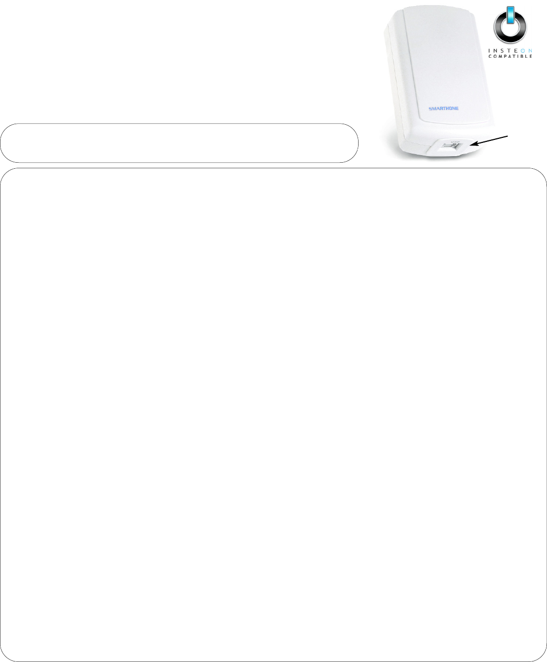
USB Interface (#2413U)
INSTEONTM PowerLinc interface with USB communications for full-time software
applications.
USB Port
NNeeeedd HHeellpp?? FFoorr aassssiissttaannccee ccaallll yyoouurr ffrriieennddllyy
ssuuppppoorrtt ppeerrssoonn @@ 880000--776622--77884466
Key Features
• No background software needed with computer programs
• Straightforward and simplified command set
• Easy and trouble free USB connection
• Stores over 2,016 INSTEON Links in 128Kb of non-volatile memory
• Communicates via powerline and RF INSTEON for maximum reliability
Connecting PowerLinc Controller Interface to the Computer
1. Insert included Driver CD into your CD-ROM Drive
Auto launch Dialog Box will appear
2. Plug PowerLinc Modem into an AC outlet, plug square end of included USB cable into PowerLinc Modem’s USB jack and
rectangular end of USB cable into an available port on your PC
Found New Hardware Wizard will appear
3. Follow instructions to add your FT232R USB UART driver
Windows will search for the proper driver, then wizard will display Completing the Found New Hardware Wizard
4. Click Finish
Another Found New Hardware Wizard dialog will appear
5. Follow instructions to add your USB Serial Port driver
Windows will search for the proper driver, then wizard will display Completing the Found New Hardware Wizard
6. Click Finish
Pairing with an Access Point
1. Be sure PowerLinc Modem is plugged in and powered (LED will blink when Set button is tapped)
2. On your PowerLinc Modem USB, tap the SET button four times rapidly
PowerLinc Modem’s LED will turn on green
3. Plug your Access Point into another outlet
4. Look at the Access Point’s Status LED:
• If it is bright and steadily on, go to step 5
• If it is blinking or dim, repeat step 3, trying another outlet
Note: You may need to try several outlets. If you are unable to locate an outlet please call 800-762-7846 for assistance.
5. Tap and release the SET button on the PowerLinc Modem, USB.
The Status LED on PowerLinc Modem will turn off and Access Point’s Status LED will go dim and remain steadily on
USB Interface (#2413U)
Quick-Start Guide
POWERLINCTM MODEM - INSTEON USB INTERFACE (DUAL BAND)
NNeeeedd HHeellpp?? FFoorr aassssiissttaannccee ccaallll yyoouurr ffrriieennddllyy
ssuuppppoorrtt ppeerrssoonn @@ 880000--776622--77884466
Tips for Using PowerLinc Modem
• Do not plug PowerLinc Modem into a power strip or AC line filter.
• Some computers and their accessories can absorb PowerLinc Carrier (PLC) signals off the power lines.
Since PowerLinc Modem will be so close to the computer, the power strip for the computer should be
filtered. Use Smarthome’s FilterLincTM #1626 on the computer’s power strip to keep the PowerLinc
Modem’s signals from getting absorbed by the computer equipment.
• Don't plug other PLC transmitters into the same outlet as PowerLinc Modem. Every PLC transmitter will
absorb the other transmitter's PLC signals when they are not transmitting. In some cases, up to half
the signal can be lost due to nearby transmitters.
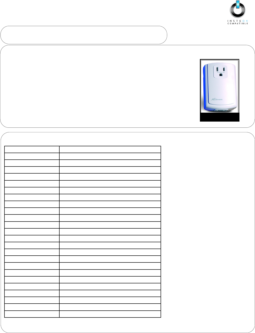
#1626 FilterLincTM
Plug-In Filter
Specifications
GGeenneerraall
SmartLabs Product Number 2413U - PowerLinc Modem Module
Warranty: 2 years
Software: Sold Separately
OOppeerraattiioonn
Operation Modes INSTEON only, X10 only, INSTEON and X10 Combo Mode
Interface USB
Connector Type Standard B-Type
FFeeaattuurreess
INSTEON Addresses 1 hard-coded out of 16,777,216
INSTEON Links 2,016 out of 16,777,216 possible
INSTEON Device Category 0x03 (Network Bridges)
INSTEON Device Sub-Category 0x15
INSTEON Powerline Freequency 131.65 kHz
Minimum Transmit Level 3.2 Vpp into 5 Ohms
Minimum Receive Level 20 mVpp nominal
INSTEON Messages Repeated Yes
X10 Powerline Frequency 121 kHz
X10 Messages Repeated No
MMeecchhaanniiccaall
Operating Conditions Indoors, 40 to 132 F, up to 85% relative humidity
Physical 3.9” H x 2.6” W x 1.5” D x 9.6 oz
EElleeccttrriiccaall
Supply Voltage 120 Volts AC +/- 10%, 60 Hertz, single phase
Certification Safety tested for use in USA and Canada (ETL #3017581)
SSmmaarrttLLaabbss LLiimmiitteedd WWaarrrraannttyy
SmartLabs warrants to the original consumer of this product that, for a period of one year from the date of purchase, this product will be free from defects in material and workmanship and will perform
in substantial conformity to the description of the product in the owner's manual. This warranty shall not apply to defects or errors caused by misuse or neglect.
IINNSSTTEEOONN aanndd TThhee IINNSSTTEEOONNCCOOMMPPAATTIIBBLLEEllooggoo aarree ttrraaddeemmaarrkkss ooff SSmmaarrttLLaabbss,, IInnc
c.. UU.. SS.. PPaattnntt NNoo.. 77,,334455,,999988 ©© CCooppyyrriigghhtt 22000099 SSmmaarrttLLaabbss,, 1166554422 MMiilllliikkaann AAvvee..,, IIrrvviinnee,, CCAA 9922660066--55002277
8
80000--776622--77884466 wwwwww..ssmmaarrttllaabbssiinncc..ccoomm
rev. 090108
FCC Compliance Statement
This device complies with FCC Rules Part 15.
Operation is subject to two conditions:
((11))This device may not cause harmful interference,
and
((22))this device must accept any interference that
may be received or that may cause undesired
operation. The digital circuitry of this device has
been tested and found to comply with the limits for
a Class B digital device, pursuant to Part 15 of the
FCC Rules. These limits are designed to provide
reasonable protection against harmful interference
in residential installations. This equipment
generates, uses and can radiate radio frequency
energy and, if not installed and used in accordance
with the instructions, may cause harmful
interference to radio and television reception.
However, there is no guarantee that interference
will not occur in a particular installation. If this
device does cause such interference, which can be
verified by turning the device off and on, the user is
encouraged to eliminate the interference by one or
more of the following measures:
•Re-orient or re-locate the receiving antenna of the
device experiencing the interference.
•Increase the distance between this device and the
receiver.
•Connect the device to an AC outlet on a circuit
different from the one that supplies power to the
receiver.
•Consult the dealer or an experienced radio/TV
technician.
WWAARRNNIINNGG!! Changes or modifications to this unit
not expressly approved by the party responsible for
compliance could void the user's authority to
operate the equipment.