SmartLabs 2421 TriggerLinc User Manual 2421 TriggerLinc QSG v7
SmartLabs, Inc. TriggerLinc 2421 TriggerLinc QSG v7
Revised Users Manual
Page 1 of 1
Rev. 111408
Quick-Start Guide
TriggerLincTM
INSTEON Door/Window, Open/Close Sensor
Models: #2421
Introduction
The TriggerLinc INSTEON Open/Close sensor is a wireless, battery operated, magnetic contact closure sensor. You
can optionally connect an external contact closure sensor of any type (e.g. Hidden contacts or Doorbell button)
Installation
Required: Access Point
TriggerLinc requires at least one INSTEON Access Point (#2443) product installed in your home, however two are strongly
recommended.
1) Remove cover of the TriggerLinc main case by using a small screwdriver, and install 1 AA battery (included)
FYI - TriggerLinc’s LED will not turn on
2) Unless the location of where you plan to mount the TriggerLinc is in direct view of the LED on an Access Point, have a
friend look at the LED on an Access Point before starting the next step.
3) In the location where you intend to mount the TriggerLinc, tap the TriggerLinc’s Set button once
TriggerLinc’s LED will flash once
Access Point’s LED will flash once or quickly flash twice. Both confirm the device with within RF range
4) If you don’t see the results mentioned in step 3, try tapping the TriggerLinc’s set button a few more times.
a. If the TriggerLinc’s LED still doesn’t flash, try another battery. If still doesn’t work, call tech support @ 1-800-
SMARTHOME (800-762-7846)
b. If the TriggerLinc’s LED flashes, but the Access Point’s LED doesn’t flash, try moving the Access Point other
locations or add another Access Point if only one is installed. If still doesn’t work, call tech support @ 1-800-
SMARTHOME (800-762-7846)
5) When mounting the TriggerLinc main case and the magnet, ensure they are as close as possible (note: magnet must be
within 1/2” for TriggerLinc to operate properly). Also, the arrows on the side of the main case and the magnet must face
each other. The included screws or double-stick tape can be used for mounting. If needed depending on the style of your
door or window frame, use some of the double stick tape beneath one of the pieces to ensure they are at the same relative
height.
6) Mount the magnet to the door or window as close to the edge as possible
7) Mount the TriggerLinc main case to the door/window trim
8) Replace TriggerLinc’s cover
Operation
1) Linking to INSTEON Responders
a. Press & hold the Set button on TriggerLinc for 5 seconds (until the red LED begins blinking, you now have 4 minutes to complete step b)
TriggerLinc’s LED will begin blinking
b. Press & hold Set button1 for 5 seconds on the INSTEON responder (e.g. SwitchLinc) you would like the TriggerLinc to control (an LED may blink and
the connected load/bulb may flash)
TriggerLinc’s LED will stop blinking (if not, try step 1-b again)
c. Test by tapping the TriggerLinc’s Set button
i. Each tap should alternatively turn the linked Responder(s) on and off
LED will flash each time Set button is tapped
d. Repeat this procedure for up to 32 responders
2) Unlinking from INSTEON Responders
a. Press & hold the Set button on TriggerLinc for 5 seconds and release
TriggerLinc’s LED will begin blinking
b. Press & hold the Set button on TriggerLinc for an additional 5 seconds
TriggerLinc’s LED will begin reverse blinking (LED will be more on than off)
c. Press & hold Set button on INSTEON responder you would like to unlink (until its LED blinks)
TriggerLinc’s LED will stop blinking (if not, try step 2-c again)
d. Test by tapping the TriggerLinc’s Set button. Taps should no longer control the unlinked device.
TriggerLinc’s LED will flash each time Set button is tapped
1 For Multi-button responders (e.g. KeypadLinc) tap the button you wish to control before Pressing & holding its Set button.
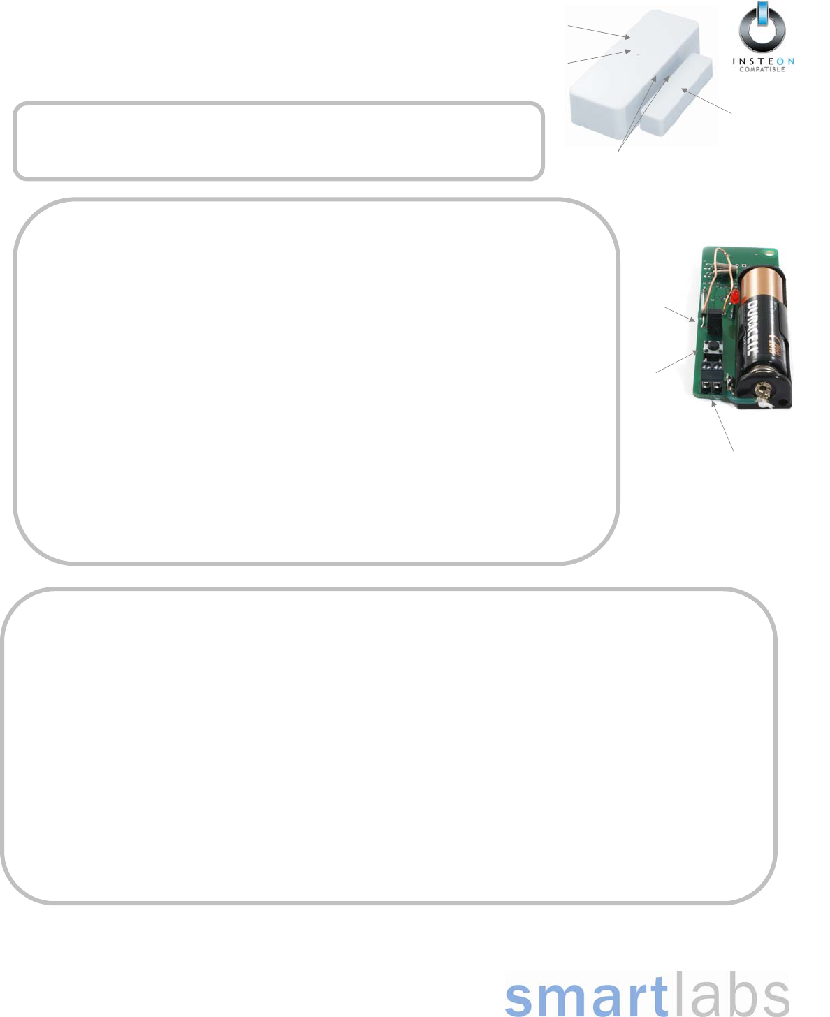
Magnet
TriggerLinc
Main Case
LED
Arrows indicating to line up main
case with magnet
External Sensor
Terminals
Set Button
Jumper
Page 2 of 1
Rev. 111408
For HELP, call our friendly tech support @ 1-800-SMARTHOME (800-762-7846)
SmartLabs Limited Warranty – SmartLabs warrants to the original consumer of this product that, for a period of two years from the date of purchase, this product will be free from defects in material and
workmanship and will perform in substantial conformity to the description of the product in the owner's manual and/or quick start guide. This warranty shall not apply to defects or errors caused by misuse
or neglect. U.S. Patent No. 7,345,998, International patents pending © Copyright 2007 SmartLabs, 16542 Millikan Ave, Irvine, CA 92606-5027 – 800-762-7846 www.smartlabsinc.com
Factory Reset
1) If possible, unlink from all responders before proceeding
2) Remove battery
3) Wait 15 seconds
4) While pressing & holding the Set button, re-attach the battery and continue holding the Set button for 3 seconds until the LED turns on for a few seconds.
TriggerLinc’s LED will turn on for a few seconds and then turn off
Optional: Wired Sensor
1) Remove cover on TriggerLinc main case
2) Connect wires to sensor
3) Store magnet for potential future use
Advanced: Multi-Scene Control
By default TriggerLinc will turn a Scene On when sensor is opened and Off when the door/window is closed. Alternatively, by moving the jumper to the “off” position,
TriggerLinc can send an On to “Scene 1” when the door/window opens and an Off to “Scene 2” when the door/window closes.
1) Remove jumper (from both pins) and replace on only one pin
2) Open door/window
3) Link to Scene 1 Responders (s) (these responders will turn on when door/window is opened)
4) Close door/window
5) Link to Scene 2 device(s) (these responders will turn off when door/window is closed)

FCC Compliance Statement
This device complies with FCC Rules Part 15. Operation is subject to two conditions:
(1) This device may not cause harmful interference
(2) this device must accept any interference that may be received or that may cause
undesired operation. The digital circuitry of this device has been tested and found to
comply with the limits for a Class B digital device, pursuant to Part 15 of the FCC
Rules.
These limits are designed to provide reasonable protection against harmful
interference in residential installations. This equipment generates uses and can
radiate radio frequency energy and, if not installed and used in accordance with the
instructions, may cause harmful interference to radio and television reception.
However, there is no guarantee that interference will not occur in a particular
installation. If this device does cause such interference, which can be verified by
turning the device off and on, the user is encouraged to eliminate the interference by
one or more of the following measures:
Re-orient or re-locate the receiving antenna of the device experiencing the
interference.
Increase the distance between this device and the receiver.
Connect the device to an AC outlet on a circuit different from the one that
supplies power to the receiver.
Consult the dealer or an experienced radio/TV technician
Warning
Changes or modifications to this unit not expressly approved by the party
responsible for compliance could void the user's authority to operate the
equipment.