SmartLabs 2441ZT Portable Wireless Zone Thermostat User Manual 2441ZT Owners Manual
SmartLabs, Inc. Portable Wireless Zone Thermostat 2441ZT Owners Manual
Users Manual
March 1, 2012
Portable Wireless Zone Thermostats
Models: 2441ZT and 2441ZTH
FCC ID: SBP2441ZT
IC: 5202A-2441ZT
The owner’s manual below may be accessed freely via the Internet
with any web browser and supports the PDF format.
http://www.smarthome.com/2441ZTH.html
Complies with Section 5 of FCC document 784748 D01 Labeling Part 15 18 Guidelines v07 where
cautionary statements in the user manual may be provided over the Internet.
On-Line Owner’s Manual Containing
Cautionary FCC & IC Statements
Page 4 of 25 Rev: 3/1/2012 3:06 PM
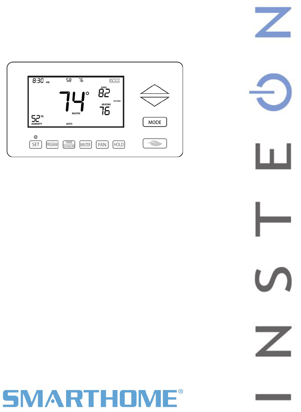
TempLinc Zone Thermostat Sample
TempLinc™ INSTEON® Zone Thermostat
Owners Manual (#2441ZTH)
The gray buttons shown above are under the door
of the TempLinc Zone Thermostat

Page 5 of 25 Rev: 3/1/2012 3:06 PM
Quick-Start Guide 1
About TempLinc Wireless Zone Thermostat 1
Preparation 1
Test Operation 1
Adding a Wireless TempLinc Zone Thermostat 2
Control Settings 2
Factory Reset 2
Owner’s Manual & Tech Support 3
About TempLinc Zone Thermostat 7
TempLinc Zone Thermostat– Features & Benefits 7
What’s in the box? 7
TempLinc Zone Thermostat Button Overview 8
TempLinc Zone Thermostat Operation and Programming 9
Thermostat Mode Button Operation 9
TempLinc Zone Thermostat Energy Button Operation 10
TempLinc Zone Thermostat Set Button Operation 11
TempLinc Zone Thermostat Time / Sensor Button Operations 11
TempLinc Zone Thermostat Program Button Operation 12
TempLinc Zone Thermostat Fan and Hold Button Operations 13
TempLinc Zone Thermostat Master Button Operation 14
Optional Waterproof Temperature Sensor Model # 2433A3 14
Installation 15
Tools Needed 15
Preparation 15
Test Operation 15
Adding a Wireless TempLinc Zone Thermostat 16
INSTEON Programming 16
Add TempLinc Zone Thermostat to a Scene as a Controller 16
Removing TempLinc Zone Thermostat as a Controller 18
User Setup Mode Overview 20
User Setup Mode 20
Temperature Calibration Mode 23
Humidity Calibration Mode 23
Advanced 2 Stage Heating or Cooling Systems 24
Factory Reset to Default 24
Certification and Warranty 25
FCC & Industry Canada Compliance Statement 25
Limited Warranty 25
Limitations 25

Page 6 of 25 Rev: 3/1/2012 3:06 PM

Page 7 of 25 Rev: 3/1/2012 3:06 PM
About TempLinc Zone Thermostat
TempLinc is a wireless, battery operated, 1-day programmable, INSTEON-compatible thermostat.
TempLinc Zone Thermostat includes a humidity sensor and the ability to communicate via RF to other
INSTEON devices and Thermostats.
TempLinc Zone Thermostat does not connect directly to the HVAC (Heating Ventilating and Air
Conditioning) system. If you want to control the HVAC system you need to install TempLinc Thermostat
and connect it directly to the HVAC system.
TempLinc Zone Thermostat may also be used as a stand alone INSTEON Controller capable of
controlling other INSTEON Responders giving notification based on temperature status, and could turn on
stand alone heaters and fans.
Expand the system by creating extra temperature zones in your home. Simply add wireless TempLinc
Zone Thermostats as accessories to your main TempLinc Thermostat Controller
TempLinc Zone Thermostat– Features & Benefits
- Installs in minutes as a table-top or wall mounted remote thermostat
- Can be added to Scenes as a Controller of INSTEON devices
- Saves energy and money on bills by remotely controlling and automating your thermostat
- Communicates wirelessly over radio frequency (RF)
- Can automatically control remote INSTEON devices when TempLinc Thermostat reaches a
specified temperature or humidity level or switches to A/C or Heat
- Reports changes in thermostat modes, temperature, humidity, setpoints and fan to compatible
automation controllers or software
- Stores setup state in memory so settings aren’t lost during battery changes or power outages
- Two-year warranty
- Controllable via the web using Smartlinc
- Battery Features:
o Goes into battery-saving standby mode 1 minute after last button press
o Wakes up every minute to get current local temp info which will remain displayed in standby
o The TempLinc includes low battery warning and a beeper
o If the temperature changes, it will do a broadcast as required to other connected devices
- When connected to always on power supply:
o Remains awake always rather than going to standby
o Participates in the INSTEON network as a message hopper
o Good for hard to reach locations such as attic or basement where battery changes may be
difficult
What’s in the box?
- TempLinc Zone Thermostat
- Quick-Start Guide
- Table-top stand (removable for wall mounting)
Page 8 of 25 Rev: 3/1/2012 3:06 PM
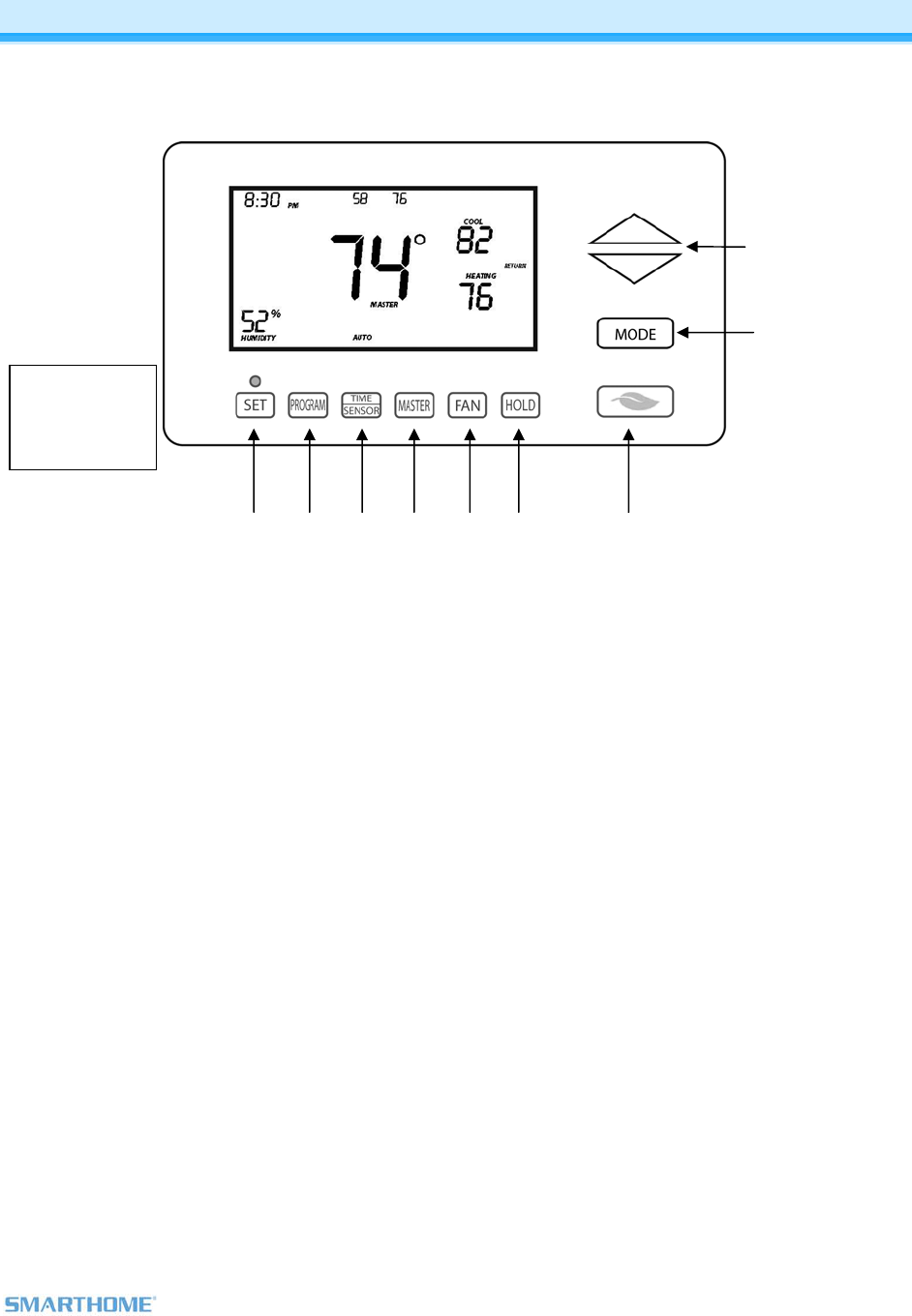
TempLinc Zone Thermostat Sample
The gray buttons
shown here are
under the door
of the TempLinc
Zone
TempLinc Zone Thermostat Button Overview
1) Up/Down adjusts the temperature setpoint based on the mode you are currently in
2) Mode allows the user to select the current operational mode of the HVAC system. It cycles
between Off, Heat, Cool, Auto, and Programmed Auto.
3) Energy button is designed as a quick access option that saves energy (and money). When
pressed, it will setback the setpoint by a specified value. The default value is 4 degrees from the
current setting. To change the default offset value to be a value other than 4 degrees, you must
use software, such as HouseLinc.
4) Hold over-rides a pre-programmed mode
5) Fan cycles between Auto and Always On – no indication given for “Auto Fan”
6) Master makes this device the master temperature controller. Pressing “Master” does not alter any
scene or screen settings. It just defines this TempLinc Zone Thermostat as the master
temperature controller.
7) Time / Sensor button allows you to set the date and time. It cycles between hour, minute, and
time format.
8) Program button allows you to setup the various pre-programmed user modes
9) Set button is for INSTEON Add to and Remove from Scenes with a TempLinc Thermostat and
other INSTEON devices. It functions like Set does for other INSTEON devices.
2
1
4 5 6 7 8 9 3
Page 9 of 25 Rev: 3/1/2012 3:06 PM
TempLinc Zone Thermostat Operation and Programming
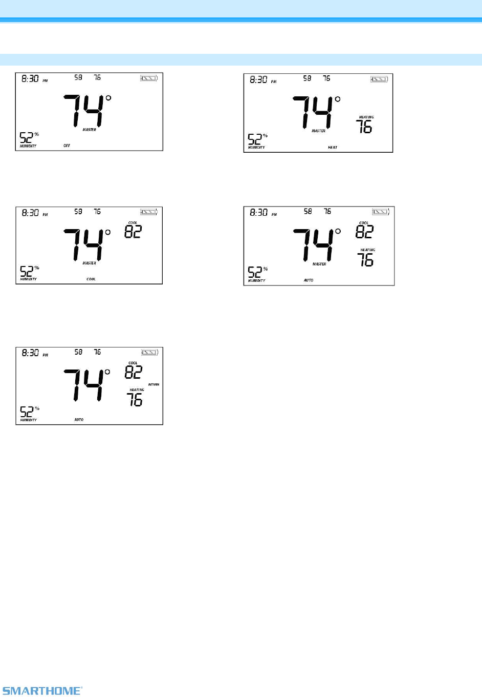
Thermostat Mode Button Operation
Off Mode:
No setpoints are shown
Up / Down do not do anything
Heat Mode:
Only Heat setpoint is shown
Up / Down changes the Heat setpoint
Cool Mode:
Only Cool setpoint is shown
Up / Down changes the Cool setpoint
Auto Mode:
Both cool and heat setpoints are shown
Up / Down move both together with a
set gap
Programmed Auto Mode:
The program mode is active in this mode
(Return annotation)
It is not in the other 4 modes (Off, Heat,
Cool and Auto)
Both Cool and Heat setpoints are shown
Up / Down move both together with a set
gap
When the thermostat moves to the next
time period, the setpoints will be adjusted
accordingly
Note: To adjust gap between the setpoints in auto mode, press mode to select Heat and set the
temperature you desire. Then press mode to select Cool and set the temperature you desire.
Press Mode button to return to Auto and the settings will reflect your changes.
Note: If you set the Heat and Cool to the same temperature, Heat will automatically be moved down 2
degrees which is the minimum allowable gap.
Page 10 of 25 Rev: 3/1/2012 3:06 PM
TempLinc Zone Thermostat Energy Button Operation
The Energy button is designed to be a very quick to use option that saves energy (and money). When
you press the Energy button (identified with the leaf), TempLinc Zone Thermostat will setback the set
points by a specified value. The default value is 4 degrees from the current setting. To change the default
offset value to be a value other than 4 degrees, you must use software.
- When you exit Energy mode, it will revert back the 4 degrees that was changed upon entry
- The unit remains in Energy mode until the Energy button is pressed again
- Up / Down adjust the temperature set point based on the mode you are in
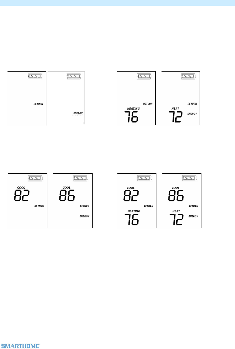
From Off Mode:
Energy button does nothing because the
system is off (at maximum energy savings
already)
When “Energy” appears on the screen for
Auto, Cool and Heat Modes, the 4 degree
setback is engaged
From Heat Mode:
Heat sets back as specified
Default setback is 4 degrees
Notice that “Heating” is active on the left, but
not on the right; the element reads “Heat”.
From Cool Mode:
Cool sets back as specified
Default setback is 4 degrees
From Auto Mode:
Both Heat and cool setpoints setback as
specified
Default setback is 4 degrees
Notice that “Heating” is active on the left, but
not on the right; the element reads “Heat”.
Page 11 of 25 Rev: 3/1/2012 3:06 PM
From Programmed Auto Mode:
Both Heat and Cool setpoints setback as
specified
Default setback is 4 degrees
Notice that “Heating” is active on the left, but
not on the right; the element reads “Heat”
Note: On screen text displaying “HEAT” changes to “HEATING” and “COOL” changes to “COOLING” to
indicate HVAC system is active. The status LED under the door also indicates current active state,
COOLING = green, HEATING = red. At time of activation either Heating or Cooling text will blink for 3
seconds then remain steady during the active cycle.
TempLinc Zone Thermostat Set Button Operation
The Set button is for INSTEON Add to and Remove from Scenes and functions like Set does for other
INSTEON devices.
TempLinc Zone Thermostat Time / Sensor Button Operations
- The Time / Sensor button allows the user to set the time and clock format
It cycles between hours, minutes and clock format
Note: When Added to a Scene with TempLinc Thermostat, it retrieves time settings automatically
- Up / Down arrows cycle through the available options.
- Go to the next Time / Sensor step by pressing Time / Sensor button again
- Exit Time / Sensor setup by:
Time out 30 seconds
Pressing any button other than Up / Down or Time / Sensor
IMPORTANT! Once you have Added TempLinc Zone Thermostat to a Scene in TempLinc Thermostat as
a wireless temperature zone, the Program and Time / Sensor buttons will no longer function. All program
and time controls will be performed on the TempLinc Thermostat.
Note: Colors indicate element that is presently blinking during setting procedure
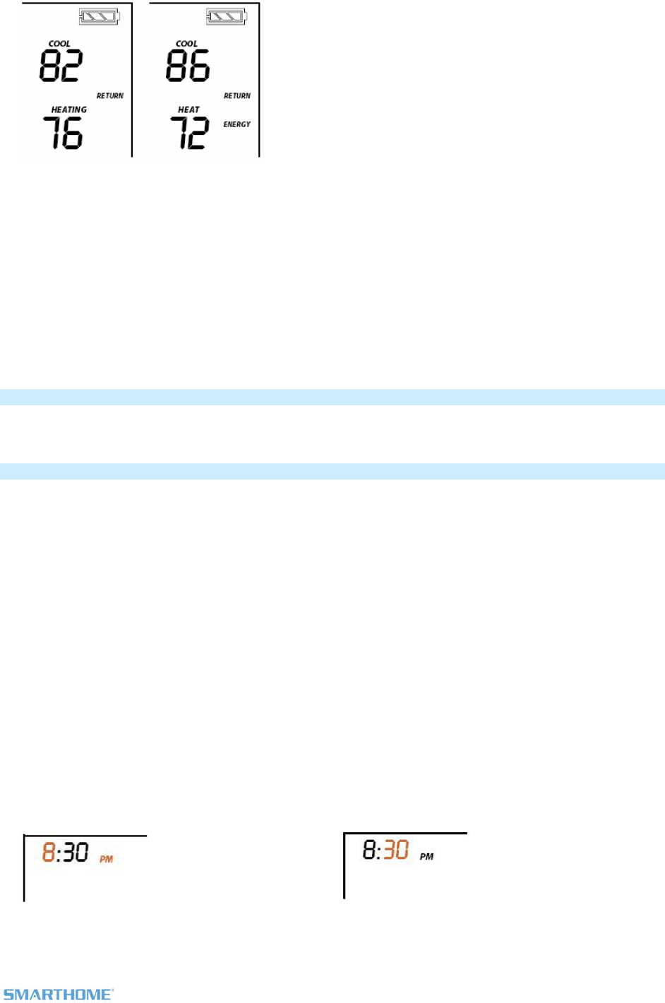
1st press of Time / Sensor:
Hours Time settings
Up / Down cycles through time in 1 hour
increments
Press and hold of Up / Down cycles faster
Note: AM / PM changes automatically as needed
2nd press of Time / Sensor:
Minutes Time setting
Up / Down cycles through time in 1 minute
increments
Press and hold of Up / Down cycles faster
Page 12 of 25 Rev: 3/1/2012 3:06 PM
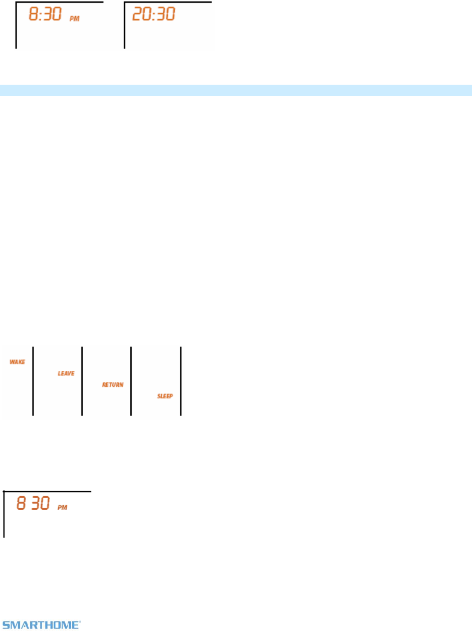
3rd press of Time / Sensor:
Clock Format setting (12 or 24 Hr clock)
Entire “time” sections blinks
Up / Down cycles between 12 and 24 Hr clock format
Note: AM / PM are not displayed when in 24 Hour format
TempLinc Zone Thermostat Program Button Operation
- The Program button allows you to setup the various pre-programmed modes (Wake, Leave, Return,
and Sleep).
- Go to the next Program step by pressing Program again
- Exit Program setup by:
Time out 30 seconds
Pressing any button other than Up, Down or Program
IMPORTANT! Once you have Added TempLinc Zone Thermostat to a Scene in TempLinc Thermostat as
a wireless temperature zone, the Program and Time / Sensor buttons will no longer function. All program
and time controls will be performed on the TempLinc Thermostat.
Note: Colors indicate element that is presently blinking during setting procedure
1st press of Program:
Selects from available pre-program modes
Up / Down cycles through Wake, Leave, Return, and Sleep
Note: Energy is not a part of this option
Note: Once a pre-programmed mode is selected, that item remains displayed throughout to
indicate what you are programming
Note: Once a pre-programmed mode is selected, the current settings are displayed on TempLinc Zone
Thermostat
2nd press of Program:
Start Time
Up / Down cycles through time in 15 minute increments
Press and hold of Up / Down cycles faster
Note: AM / PM changes automatically as needed
Note: The start of one program mode is also the end of the previous program mode
Page 13 of 25 Rev: 3/1/2012 3:06 PM
3rd press of Program:
Cool setpoint
Up / Down cycles through temperature
4th press of Program:
Heat setpoint
Up / Down cycles through temperature
5th press of Program:
- Starts the process all over again to program another Mode
Note: The 4 modes come pre-programmed. The defaults are:
4 Day Modes Start Time Thermostat Mode Heat Setting Cool Setting
Wake 6AM Auto 65 75
Leave 8:30AM Auto 60 80
Return 5:00PM Auto 65 75
Sleep 11:00PM Auto 60 80
Note: To exit mode press Mode button once
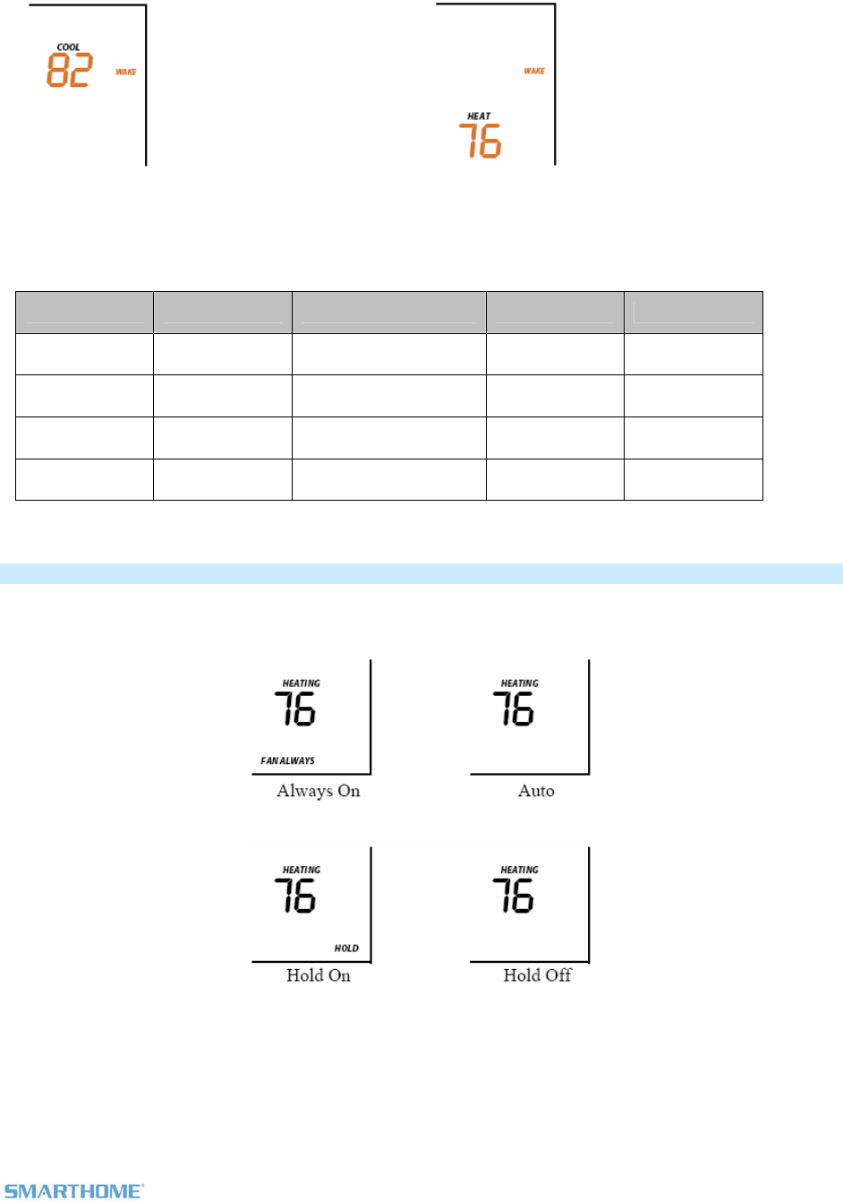
TempLinc Zone Thermostat Fan and Hold Button Operations
Fan button operations
- The Fan button cycles between Auto and Always On.
- On the display, it simply indicates the text “Fan Always” when selected. No indication for “Auto”.
Hold button operations
- The Hold button over-rides a pre-programmed mode until Hold is turned off:
Note: While the hold is enabled, when the next pre-programmed time comes in Programmed Auto
Mode it will be ignored
Note: While hold is enabled, the Programmed Auto time notations are not shown
(i.e. Wake, Leave, Return and Sleep)
Page 14 of 25 Rev: 3/1/2012 3:06 PM
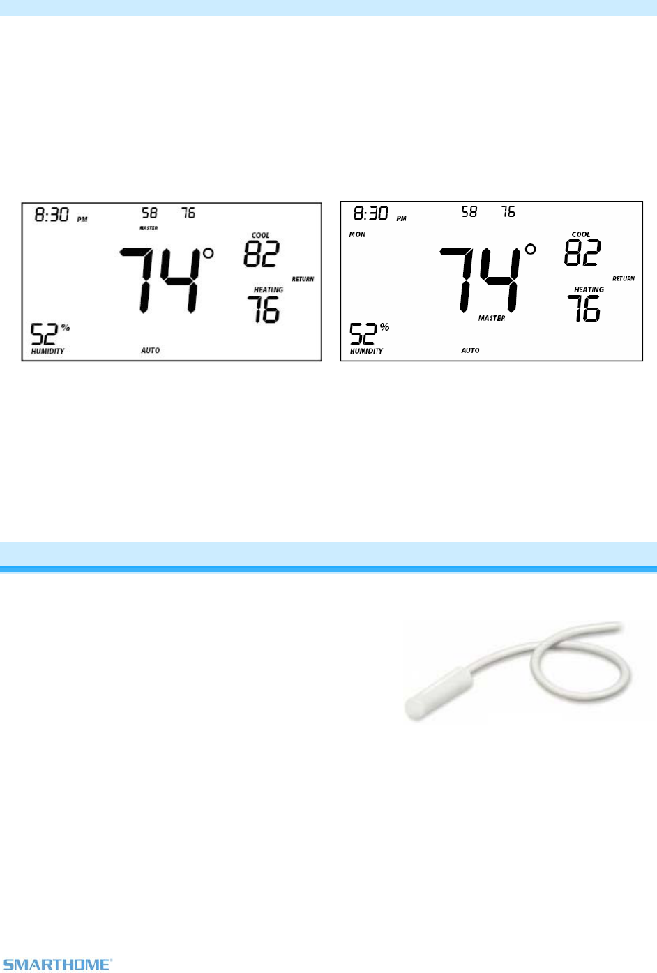
TempLinc Zone Thermostat Master Button Operation
The Master button makes the local device the Master temperature Controller. The logic behind this is that
as the user walks around the home, they would likely want to have the local temp be the controlling temp.
Since this button will only set the local to be Master, pressing the button a second time does not change
anything.
1st press:
Makes the local TempLinc Zone Thermostat the master
To perform this, press and hold Master button for 3 seconds
TempLinc Zone Thermostat beeps once
Release
Before pressing Master button:
Notice that the left remote sensor is currently
the Master temperature controller
After pressing Master button:
Notice that the left remote sensor is no
longer the Master temperature controller
The local temp now is Master controlling
temperature
Note: If no TempLinc Thermostat is added to TempLinc Zone Thermostat, then Master button will have no
function
Optional Waterproof Temperature Sensor Model # 2433A3
The waterproof sensor has:
6’ cable
Bare leads to connect into TempLinc Zone Thermostat
(allows it to be user extendable to 100 feet)
Waterproof design
Same color and look as TempLinc Zone Thermostat
designed to be mated
When plugged in, the TempLinc Zone Thermostat will
display the temperature from the Sensor instead of the
internal monitor
Use case:
Monitor pools, spas, ponds, and fish tanks
To sense and / or maintain constant temperature in those items

Page 15 of 25 Rev: 3/1/2012 3:06 PM
Installation
CAUTIONS AND WARNINGS
Read and understand these instructions before installing and retain them for future reference.
Tools Needed
- TempLinc Zone Thermostat will primarily be used as a table-top thermostat
- If desired, you may wall mount TempLinc Zone Thermostat using the slotted holes in the back cover
of TempLinc1
Preparation
Proper installation of the TempLinc Zone thermostat will be accomplished by following these steps.
However, the main use for this product will be table-top. Wall mounting is optional.
4) Make sure the location that you have selected for the TempLinc Zone Thermostat will not be affected
by daily movement of sunlight or in direct line of sight to a nearby HVAC vent or fan
5) Insert 2 AA batteries into TempLinc Zone Thermostat
6) Close the cover of TempLinc Zone thermostat
- After a few seconds TempLinc Zone Thermostat will display ambient temperature and humidity
- Mode will default to OFF
- Battery segment should show full with fresh batteries
- Time will show default 12:00pm and will become active
5) Snap TempLinc Zone Thermostat into the supplied table-top stand or mount safely to a wall
Test Operation
The wireless TempLinc Zone Thermostat does not directly control the HVAC system. Instead, TempLinc
Zone Thermostat communicates via RF to TempLinc Thermostat which is directly in contact to the wiring
controlling the HVAC system.
Before Adding to a Scene as a Responder or Controller of TempLinc Thermostat perform the following
tests; this will help to familiarize you with TempLinc Zone Thermostat. Keep in mind you are not yet
sending any communication to any INSTEON device. The TempLinc Zone Thermostat is presently a
stand alone device.
Note: While testing, no HVAC operations will take place, only display changes
TempLinc Zone Thermostat defaults 10 minutes delay between cycling the AC
compressor
Heating Mode Test
12) Press mode button once to enter Heat mode
13) Tap the up or down arrow several times until set point is 1 degree above ambient
TempLinc Zone Thermostat will call for Heat
“Heat” segment changes to “Heating” and will blink for 3 seconds then goes steady
Status LED will display red
No furnace activity will take place at this time, only display changes
14) Tap the up or down arrow until you reach a desirable heat temperature set point below ambient
Cooling Mode Test
15) Tap mode button once again to enter Cool mode
16) Tap the up or down arrow several times until set point is 1 degree below ambient
TempLinc Zone Thermostat will call for Cooling
“Cool” segment changes to “Cooling” and will blink for 3 seconds then goes steady
Status LED will display green
No A/C activity will take place at this time, only display changes
17) Tap the up or down arrow until you reach a desirable cool temperature set point
1 Screws and wall anchors not provided

Page 16 of 25 Rev: 3/1/2012 3:06 PM
Auto Mode Test
18) Tap mode button once to enter auto mode
19) Note that your Heat and Cool set points are set in previous steps, unless you did not have a
minimum 2 degrees gap between settings
20) Tap up once to increase both Heat and Cool set points by one degree
21) Tap down once to decrease both Heat and Cool set points by one degree
22) Tap mode once to enter Programmed Auto mode
Indicated by Auto at bottom and relevant time of day to right of Heat/Cool set temps
13) Tap mode once more to return to Off mode
Adding a Wireless TempLinc Zone Thermostat
TempLinc Zone Thermostat can be added to TempLinc Thermostat to provide a portable thermostat
wherever you want temperature control. You can add up to 2 TempLinc Zone Thermostats to a TempLinc
Thermostat.
4) Press & hold Set button on TempLinc Zone Thermostat
TempLinc Zone Thermostat Set LED blinks GREEN and unit beeps
5) Press & hold TempLinc Thermostat Set button
TempLinc Zone Thermostat will (Beep), then (Beep)-(Beep)
TempLinc Thermostat will (Beep)-(Beep)
6) Test the Scene by pressing the Master button on the TempLinc Zone Thermostat
- When properly Synchronized, pressing the Master button on one TempLinc Zone Thermostat will
illuminate the “Master” segment on that same screen. Additionally, the present room temperature
of the TempLinc Zone Thermostat will be displayed in position 1on the TempLinc Thermostat as
the small temperature segments at the top center of the display.
- A visual inspection of each display will reveal Master status of TempLinc Thermostat or Zone
Thermostat.
Note: Only the TempLinc Thermostat is directly connected to the HVAC system via wires. If you plan on
operating multiple Zone Thermostats you must have at least one TempLinc Thermostat to control the
HVAC.
INSTEON Programming
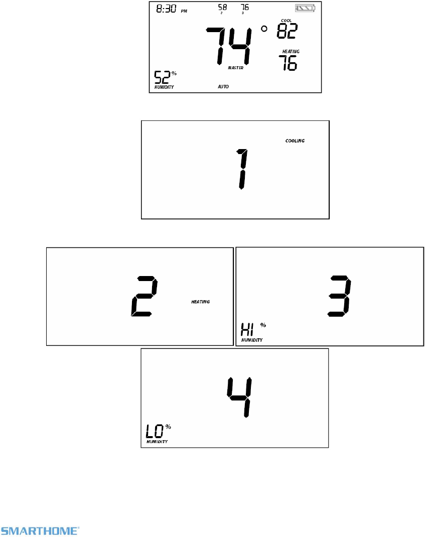
Add TempLinc Zone Thermostat to a Scene as a Controller
TempLinc Zone Thermostat can be setup to control other INSTEON devices or trigger software events
when there is a change. The following TempLinc Zone Thermostat changes can be setup as a Controller:
- Group 1 - Cooling mode change (scene control)
- Group 2 - Heating mode change (scene control)
- Group 3 – De-humidification, high humidity setpoint (scene control)
- Group 4 - Humidification, low humidity setpoint (scene control)
- Group FE - broadcast on any change (info only)*
- * Can only be configured via software.
NOTE: A TempLinc Zone Thermostat can also be added to a Scene as a Controller to Groups 1 - 4.
When it is added as a Controller of a TempLinc Thermostat, the setpoints between TempLinc Zone
Thermostat and TempLinc Thermostat will always be matched. When it is not added as a Responder or
Controller to a TempLinc Thermostat, the setpoints are local only. TempLinc Zone Thermostat will send
group commands based on local temp or humidity level and the setpoint shown on the display, regardless
of whether it’s added as a Responder or Controller to a TempLinc Thermostat or not.
Page 17 of 25 Rev: 3/1/2012 3:06 PM
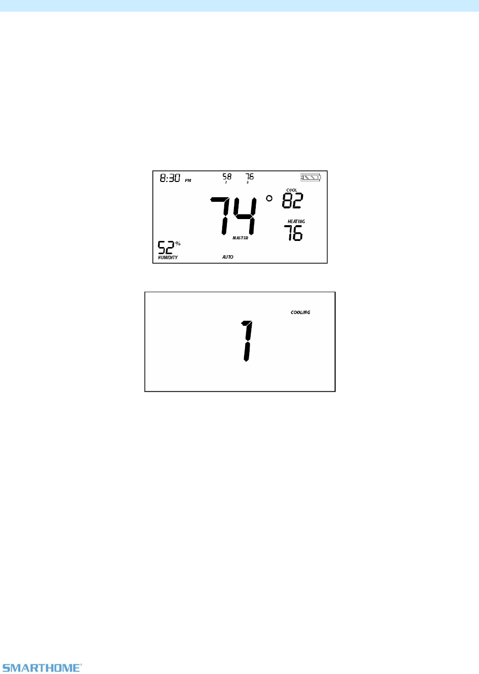
Add to a Scene Process:
1) Press & hold TempLinc Zone Thermostat Set button until it beeps
TempLinc Zone Thermostat Set LED blinks GREEN
TempLinc Zone Thermostat will (Beep)
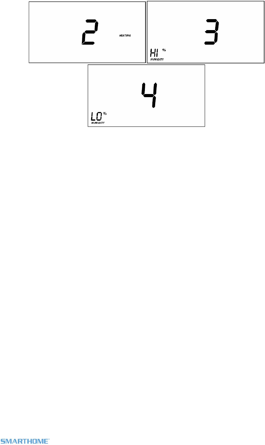
2) Tap:
Up or Down buttons to select Group 1 – 4 to Add to a Scene
Group 1 - Cooling mode change, default
Group 2 - Heating mode change
Group 3 – De-humidification, high humidity setpoint
Group 4 - Humidification, low humidity setpoint
3) Adjust Scene Responder, such as OutletLinc with connected humidifier, to the “state” you want when
Scene is activated (e.g., 50%, 25% or even OFF)
Upon entering Scene mode this screen will display for ~ 2 seconds
LCD display if press Up button or after 2 seconds
LCD display when using Up or Down buttons to select from among the 4 Controller Groups
4) Press and hold Responder’s Set button
Page 18 of 25 Rev: 3/1/2012 3:06 PM
TempLinc Zone Thermostat will (Beep)-(Beep) upon completion
LED returns to previous state
Removing TempLinc Zone Thermostat as a Controller
1) Press & hold TempLinc Zone Thermostat’s Set button until it beeps
TempLinc Zone Thermostat Set LED blinks GREEN
TempLinc Zone Thermostat will (Beep)
2) Press & hold TempLinc Zone Thermostat’s Set button again until it beeps
TempLinc Zone Thermostat Set LED blinks RED
TempLinc Zone Thermostat will (Beep)
LCD display indicates the group that you are removing Scene from
3) Tap:
Use Up and Down buttons to select appropriate Group to remove from:
Group 1 - Cooling mode change, default
Group 2 - Heating mode change
Group 3 - Dehumidifiation, high humidity setpoint
Group 4 - Humidification, low humidity setpoint
Upon entering Add a Scene mode
Upon entering Remove a Scene mode
Defaults to Cooling mode
Page 19 of 25 Rev: 3/1/2012 3:06 PM
LCD display when using Up or Down buttons to select from among the 4 Controller Groups
4) Press and hold Responder’s Set button
TempLinc Zone Thermostat will (Beep)-(Beep) upon completion
LED returns to previous state
Page 20 of 25 Rev: 3/1/2012 3:06 PM
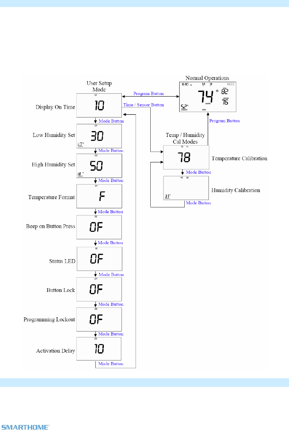
User Setup Mode Overview
IMPORTANT! Once you have Added TempLinc Zone Thermostat to TempLinc Thermostat as a wireless
temperature zone, the Program and Time / Sensor buttons will no longer perform their initial function. All
program and time controls will be performed on the TempLinc Thermostat. To access the Program and
Time / Sensor buttons again, you must Remove TempLinc Zone Thermostat from TempLinc Thermostat.
Program and Time / Sensor buttons can be used to wake TempLinc Zone Thermostat up from its battery
saving mode to retrieve any updates from TempLinc Thermostat
Press and hold Program button for 3 seconds or more to enter the User Setup Mode
User Setup Mode
1) Press and hold the Program button to access the following options:
- Press Mode to step between menu items
Page 21 of 25 Rev: 3/1/2012 3:06 PM
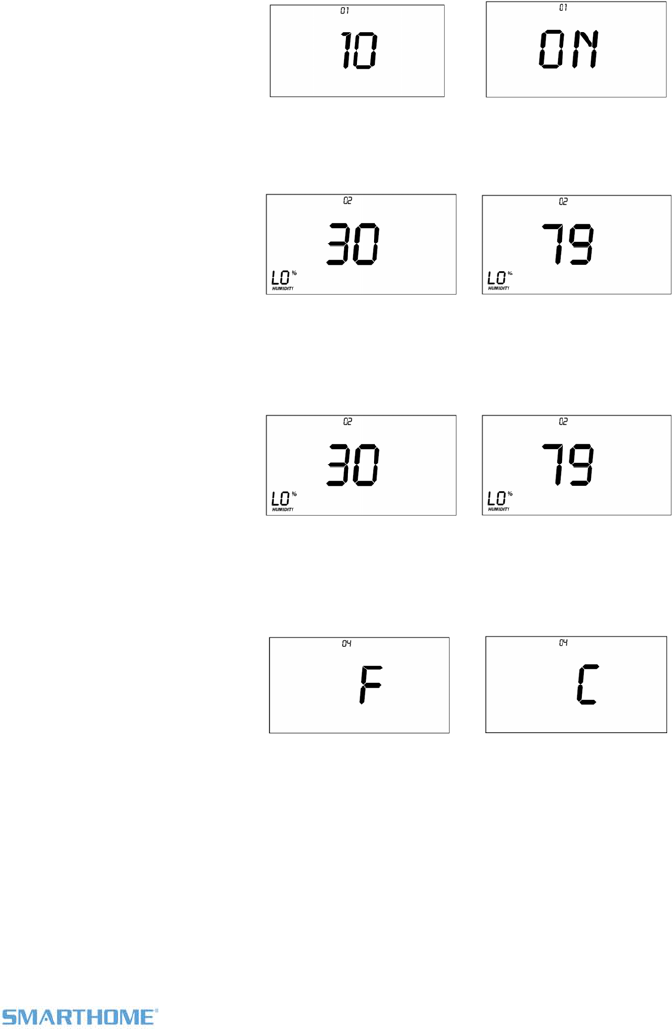
- Sub-mode 01: Display LED on-time select (Default is 10 seconds)
- Sub-mode 02: Humidity Low Set Point (Default is 30%)
- Sub-mode 03: Humidity High Set Point (Default is 50%)
- Sub-mode 4: Temperature format select (Default is Fahrenheit)
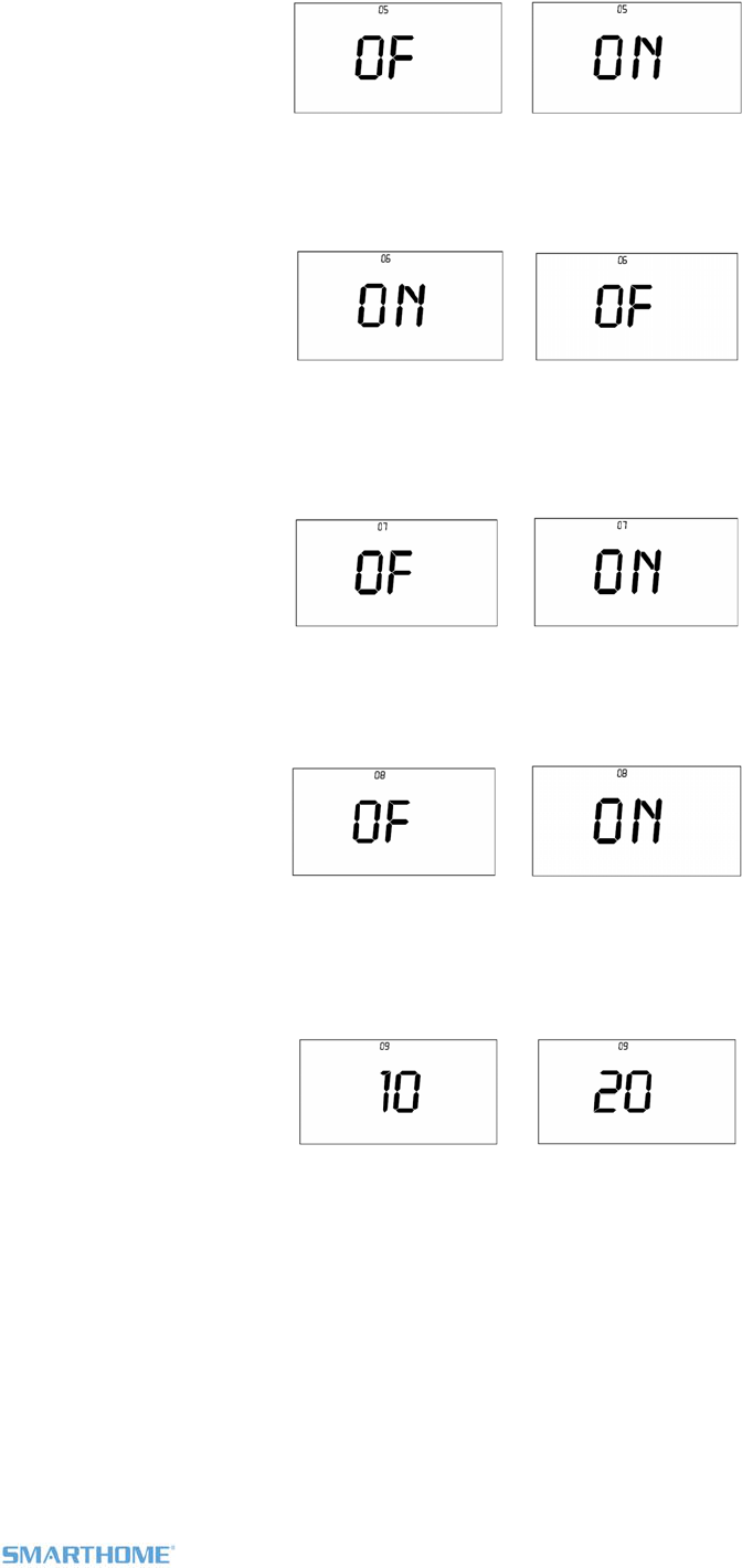
- Sub-mode 5: Beep on button press (Default is Off)
- Sub-mode 6: Status LED (Default is On)
- Sub-mode 7: Button Lock (Default is Off)
- Sub-mode 8: Programming lock (Default is Off)
- Sub-mode 9: Activation Delay (Default is 10 minutes)
2) Press the Up or Down button to change a setting
Sub- mode 01: LED Backlight on time, 10 seconds default
a. Up button = 5 second increments longer
b. Down button = 5 second increments shorter
c. Options:
o Off always
o On for 5 – 95 seconds in 5 second increments
o On always
Sub-mode 02: Humidity Low Set Point (humidification), 30% default
a. Up button = Increase humidity % setpoint
b. Down button = Decrease humidity % setpoint
Sub-mode 03: Humidity High Set Point (dehumidification), 50% default
c. Up button = Increase humidity % setpoint
d. Down button = Decrease humidity % setpoint
Sub- mode 04: Temperature format select (C or F), F default
e. Up button = C
f. Down button = F
Sub-mode 05: Beep on button press (Enable / Disable), Off default
b. Up button = On
c. Down button = Off
Page 22 of 25 Rev: 3/1/2012 3:06 PM
Sub- mode 06: Status LED(Enable / Disable), On default
a. Up button = On
b. Down button = Off
Sub- mode 07: Button Lock (disables front button presses), Off default
o For common area locations in a business such as a lobby
c. Up button = On
d. Down button = Off
Sub- mode 08: Programming lock (Locks out programming operations), Off default
a. Up button = On
b. Down button = Off
Sub- mode 09: Delay between consecutive AC modes, 10 minutes default
a. Up button = adds 1 minute increments
b. Down button = decreases 1 minute increments
c. Range = 2 to 20 minutes
Page 23 of 25 Rev: 3/1/2012 3:06 PM
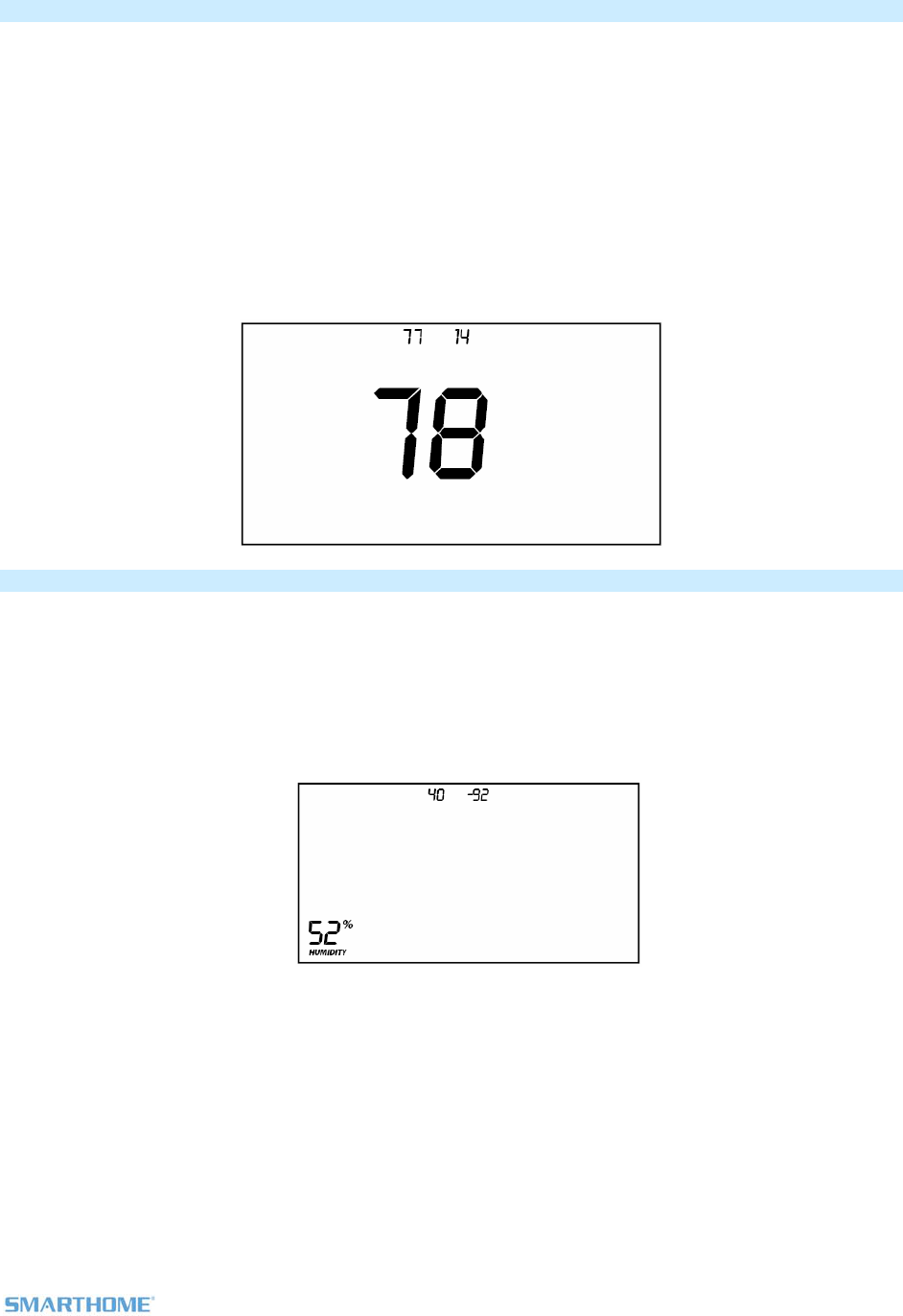
Temperature Calibration Mode
1) Once in User Setup Mode, press the Time / Sensor button to enter Temperature Calibration Mode
2) Press Mode to step between Temperature Calibration and Humidity Calibration
3) Temperature Calibration
a. Press up and down arrow to adjust the displayed temp
i. Each press results in a 1 degree change
ii. The calculation using example numbers below is 78 = 77 + 1.4
iii. The offset range is from –10 to +10
b. The top left number (77 in example) is current reading according to the temperature sensing chip
c. The top right number (14 in example) is the current offset
d. These numbers can change while this screen is displayed even though the primary temp does
not change because they are actually floating point calculations
Humidity Calibration Mode
4) Once in Temperatur Calibration Mode, press the Mode button to enter Humidity Calibration Mode
5) Press the Up or Down button to select the current humidity level
The top numbers represent:
i. 40 is what the humidity sensor sees
ii. -92 the offset from current reading
iii. The offset is from -10 to +10
iv. The displayed number needs to be multiplied by 0.1 to get the actual offset
6) Press Program to exit the Calibration mode

Page 24 of 25 Rev: 3/1/2012 3:06 PM
Advanced 2 Stage Heating or Cooling Systems
TempLinc Zone does not have the ability to operate 1st or 2nd stages of Heat or Cool directly but can
instruct TempLinc Thermostat to operate the HVAC. 1st and 2nd stage of Heat or Cool engages under the
following conditions when TempLinc Thermostat is connected to the HVAC:
- TempLinc Zone Thermostat’s setpoint is set at 5 degrees or more below ambient in Cool
mode and 5 degrees or more above ambient in Heat mode
o i.e. Heat mode setpoint is 80°, ambient is 72° = 1st and 2nd stage engaged
o i.e. Cool mode setpoint is 78°, ambient is 84° = 1st and 2nd stage engaged
- TempLinc Zone Thermostat has been active in Heat or Cool for longer than 10 minutes
and did not reach setpoint
o i.e. Heat mode ran for 10 minutes and no change to ambient = 2nd stage engaged
o i.e. Cool mode ran for 10 minutes and no change to ambient = 2nd stage engaged
Note: It is possible for TempLinc Thermostat to occasionally engage and disengage 2nd stage during a
single Heating or Cooling cycle as variables are met
Factory Reset to Default
Factory Reset Changes
INSTEON is reset (all links removed)
Day / time is changed to 12:00, Monday
Programming times, temperatures and other settings are reset to their default value
Factory Reset Does Not Change
Temperature offset
Humidity Offset
F or C setting
Reset Option 1
5) Open TempLinc Zone Thermostat and remove a battery
6) Wait 10 seconds
7) While continuously holding the Set button ~10 seconds, re-insert the removed battery
Device will blink all segments and do continuous (Beep) during 10 seconds
8) When blinking / buzzing stops, release Set button
Device goes into factory reset for ~10 seconds and will perform a series of self tests.
Device will return to normal operations and display screen returns to normal
Reset Option 2
9) Press & hold TempLinc Zone Thermostat Set button until it beeps
TempLinc Zone Thermostat Set LED blinks GREEN
TempLinc Zone Thermostat will (Beep)
10) Press & hold TempLinc Zone Thermostat Set button again until it beeps
TempLinc Zone Thermostat Set LED blinks RED
TempLinc Zone Thermostat will (Beep)
LCD display indicates the group that you are unlinking from (default is cooling)
11) Double tap the Set button
12) Press and hold the set button again for ~10 seconds
Device will blink all segments and do continuous (Beep) during 10 seconds
13) When blinking / buzzing stops, release Set button
Device goes into factory reset for ~10 seconds and will perform a series of self tests.
Device will return to normal operations and display screen returns to normal

Page 25 of 25 Rev: 3/1/2012 3:06 PM
Certification and Warranty
FCC & Industry Canada Compliance Statement
This device complies with FCC Rules Part 15C and Industry Canada RSS-210 (Rev. 8). Operation is subject to the following two conditions:
(1) This device may not cause harmful interference, and
(2) This device must accept any interference, including interference that may cause undesired operation of the device.
Le present appareil est conforme aux CNR d'Industrie Canada applicables aux appareils radio exempts de licence. L'exploitation est autorise aux deux
conditions suivantes:
(1) l'appareil ne doit pas produire de brouillage, et
(2) l'utilisateur de l'appareil doit accepter tout brouillage radiolectrique subi, mme si le brouillage est susceptible d'en compromettre le
fonctionnement.
The digital circuitry of this device has been tested and found to comply with the limits for a Class B digital device, pursuant to Part 15B of the FCC
Rules. These limits are designed to provide reasonable protection against harmful interference in residential installations. This equipment generates,
uses, and can radiate radio frequency energy and, if not installed and used in accordance with the instructions, may cause harmful interference to radio
and television reception. However, there is no guarantee that interference will not occur in a particular installation. If this device does cause such
interference, which can be verified by turning the device off and on, the user is encouraged to eliminate the interference by one or more of the following
measures:
- Re-orient or relocate the receiving antenna of the device experiencing the interference
- Increase the distance between this device and the receiver
- Connect the device to an AC outlet on a circuit different from the one that supplies power to the receiver
- Consult the dealer or an experienced radio/TV technician
WARNING: Changes or modifications to this device not expressly approved by the party responsible for compliance could void the user’s authority to
operate the equipment.
Limited Warranty
Seller warrants to the original consumer purchaser of this product that, for a period of two years from the date of purchase, this product will be free
from defects in material and workmanship and will perform in substantial conformity to the description of the product in this Owner’s Manual. This
warranty shall not apply to defects or errors caused by misuse or neglect. If the product is found to be defective in material or workmanship, or if the
product does not perform as warranted above during the warranty period, Seller will either repair it, replace it, or refund the purchase price, at its
option, upon receipt of the product at the address below, postage prepaid, with proof of the date of purchase and an explanation of the defect or error.
The repair, replacement, or refund that is provided for above shall be the full extent of Seller’s liability with respect to this product. For repair or
replacement during the warranty period, call the INSTEON Gold Support Line at 800-762-7845 with the Model # and Revision # of the device to receive
an RMA# and send the product, along with all other required materials to:
Smarthome
ATTN: Receiving
16542 Millikan Ave.
Irvine, CA 92606-5027
Limitations
The above warranty is in lieu of and Seller disclaims all other warranties, whether oral or written, express or implied, including any warranty or
merchantability or fitness for a particular purpose. Any implied warranty, including any warranty of merchantability or fitness for a particular purpose,
which may not be disclaimed or supplanted as provided above shall be limited to the two-year of the express warranty above. No other representation
or claim of any nature by any person shall be binding upon Seller or modify the terms of the above warranty and disclaimer.
Home automation devices have the risk of failure to operate, incorrect operation, or electrical or mechanical tampering. For optimal use, manually verify
the device state. Any home automation device should be viewed as a convenience, but not as a sole method for controlling your home.
In no event shall Seller be liable for special, incidental, consequential, or other damages resulting from possession or use of this device, including
without limitation damage to property and, to the extent permitted by law, personal injury, even if Seller knew or should have known of the possibility of
such damages. Some states do not allow limitations on how long an implied warranty lasts and/or the exclusion or limitation of damages, in which case
the above limitations and/or exclusions may not apply to you. You may also have other legal rights that may vary from state to state.
U.S Patent No. 7,345,998, International patents granted and pending
© Copyright 2011 Smarthome, 16542 Millikan Ave., Irvine, CA 92606, 800-762-7845, www.smarthome.com