SmartLabs 2475DA2 In-Line 0-10VDC Dimmer or Dual-Switch User Manual 2475SA2 Owners Manual
SmartLabs, Inc. In-Line 0-10VDC Dimmer or Dual-Switch 2475SA2 Owners Manual
Users Manual

November 10, 2011
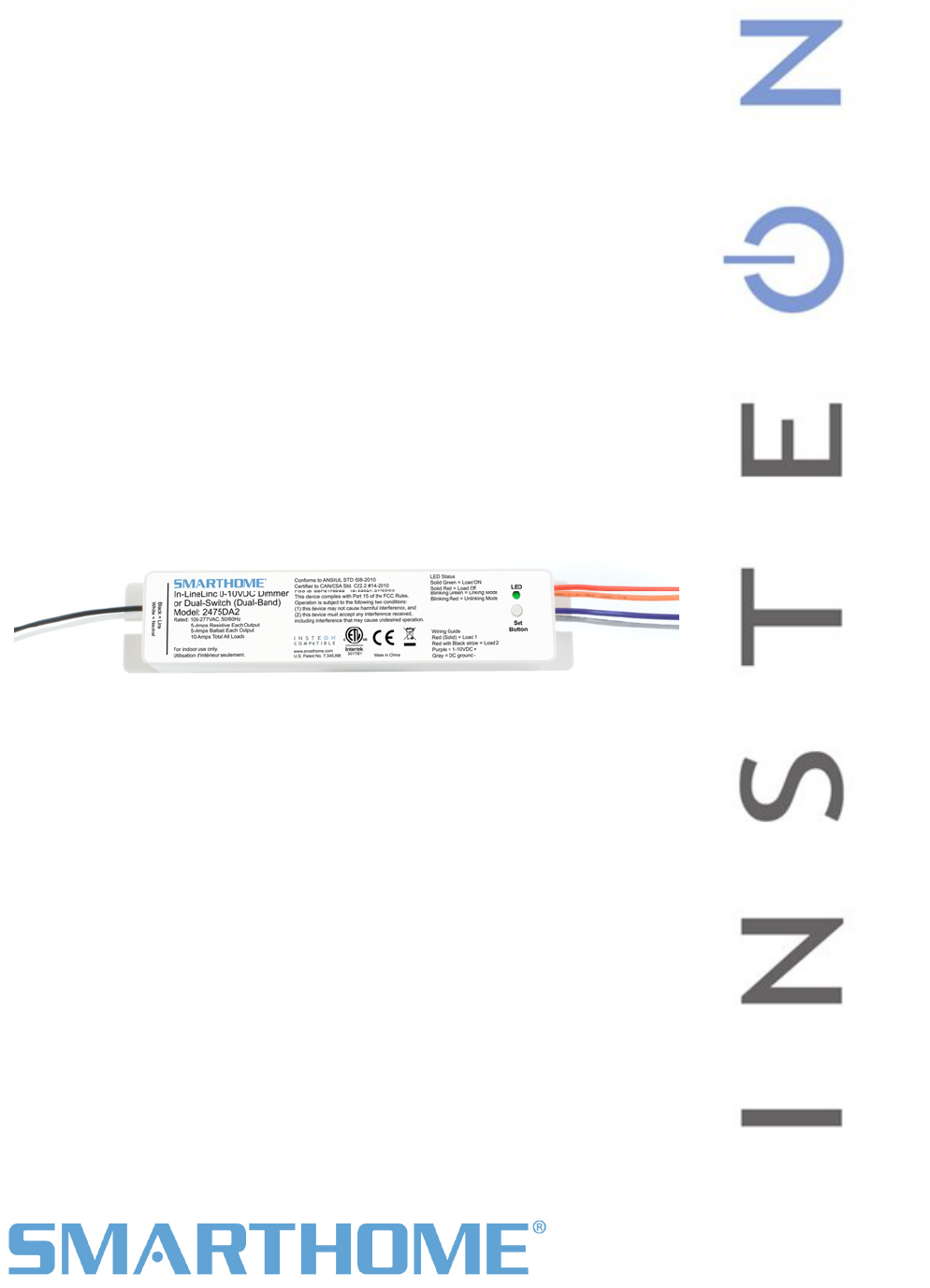
In-Line 0-10VDC Dimmer or Dual-Switch
Model: 2475DA2
FCC ID: SBP2475DA2 IC: 5202A-2475DA2
The owner’s manual below may be accessed freely via the Internet
with any web browser and supports the PDF format.
www.smarthome.com/2475DA2.html
Complies with Section 5 of FCC document 784748 D01 Labeling Part 15 18 Guidelines v07 where
cautionary statements in the user manual may be provided over the Internet.
On-Line Owner’s Manual Containing
Cautionary FCC & IC Statements
Page 1 of 12 2475DA2 Rev: 11/10/2011 9:41 AM
In-LineLinc
®
Control In-Line 0-10VDC Dimmer or Dual
)
Owners Manual
INSTEON Remote
Switch (#2475DA2

Page 2 of 12 2475DA2 Rev: 11/10/2011 9:41 AM
In-LineLinc ................................................................................................................................................... 3
. ........................... 3
.. ........................... 3
...................... 4
4
. ........................... 4
.. ................... 4
.. ........................... 4
.. ........................... 5
.. ........................... 6
. ........................... 7
.. ................... ..... 7
.. ................... ..... 7
. ........................... 7
... .................... ...... 7
... ........................... 8
... ................... 8
... ................... ..... 9
T.. ......................... 11
Certification and Warranty ....................................................................................................................... 12
Certification.............................................................................................................................................. 12
FCC & Industry Canada Compliance Statement.....................................................................................12
Limited Warranty ..................................................................................................................................... 12
Limitations............................................................................................................................................ 12
Features & Benefits ..................................................................................................... ...
What’s in the Box?...................................................................................................... ..
Optional Accessories...........................................................................................................
Getting Started ............................................................................................................................................
Installing In-LineLinc ................................................................................................... ...
........Identifying the Electrical Wires in your installation location........................................ ..
Tools Needed ............................................................................................................. ..
Installing In-LineLinc for Dimmable Ballast ................................................................ ..
Installing In-LineLinc in Relay Mode........................................................................... ..
INSTEON Programming............................................................................................... ...
...
Adding In-LineLinc to a Scene as a Responder......................................................... .. ...
Removing In-LineLinc from a Scene as a Responder................................................ ..
.
Advanced Features ...................................................................................................... ...
Using In-LineLinc as a Phase Bridge (Phase Bridging Detection Mode).................. ..
........
Restoring Power to In-LineLinc ................................................................................. ..
Resetting In-LineLinc to its Factory Default Settings ................................................ ..
...Specifications.............................................................................................................. ..
roubleshooting.......................................................................................................... ...
Page 3 of 12 2475DA2 Rev: 11/10/2011 9:41 AM
In-LineLinc
The In-LineLinc Dimmer/Dual-Relay is an in-line INSTEON ballast control module that supports 2 different
operational modes: Dimmer Mode and a Dual-Relay Mode. For use in new construction or retrofit (inside
or outside the fixture) where saving energy is a priority.
Features & Benefits
Controls dimmable ballasts with 0-10VDC trigger
ltages of 100VAC to 277VAC
t) for international compatibility
to 5A
for setup ease
tored in stable memory which is maintained even without power
y
Dual-Mode offers control of two non-dimmable ballasts
Supports vo
50/60Hz (auto-detec
Dual-relay – each relay supports up
Beeper
All settings s
2 year warrant
What’s in the Box?
In-LineLinc 0-10VDC Dimmer or Dual-Relay
6 Wire Nuts
Mounting Screws
Quick-Start Guide
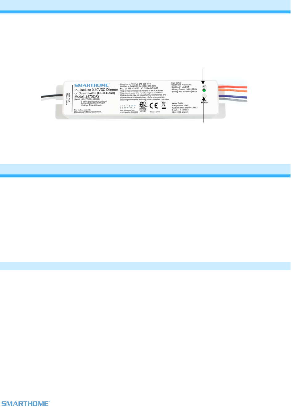
Line -
Neutral -
Set button
LED
-Load 1
-Load 2
-1-10VDC +
-DC ground
Page 4 of 12 2475DA2 Rev: 11/10/2011 9:41 AM
Optional Accessories
(100VAC-277VAC)
KeypadLinc Dimmer (120VAC)
KeypadLinc Relay 2487S
Getting Started
Map out the wall switch and load that you are going to remotely operate. Keep in mind that you are going
to replace the existing wall switch with a KeypadLinc and wire both the KeypadLinc and the In-LineLinc to
using the existing wiring.
the same constant hot line
Installing In-LineLinc
CAUTIONS AND WARNINGS
Read and understand these instructions before installing and retain them for future reference.
This product is intended for installation in accordance with the National Electric Code and local regulations in the United States or
the Canadian Electrical Code and local regulations in Canada. Use indoors only. This product is not designed or approved for
use on power lines other than 100VAC- 277VAC 50/60Hz, single phase. Attempting to use this product on non-approved power
lines may have hazardous consequences.
- Use only indoors or in outdoor rated box
- Be sure that you have turned off the circuit breaker or removed the fuse for the circuit you are installing this product into.
Installing this product with the power on will expose you to dangerous voltages.
- Connect using only copper or copper-clad wire
- This product may feel warm during operation. The amount of heat generated is within approved limits and poses no
hazards. To minimize heat buildup, ensure the area surrounding the rear of this product is as clear of clutter as possible.
- Each INSTEON product is assigned a unique INSTEON ID, which is printed on the product’s label.
- To reduce the risk of overheating and possible damage to other equipment, do not use this product to control loads in
excess of the specified maximum(s) or, install in locations with electricity specifications which are outside of the product’s
specifications. If this device supports dimming, please note that dimming an inductive load, such as a fan or transformer,
could cause damage to the dimmer, the load bearing device, or both. If the manufacturer of the load device does not
recommend dimming, use a non-dimming INSTEON on/off switch. USER ASSUMES ALL RISKS ASSOCIATED WITH
DIMMING AN INDUCTIVE LOAD.
Identifying the Electrical Wires in your installation location
- LINE - usually black, may also be called HOT or LIVE, carries from 120 to 277VAC electricity into the switch box and to the
fixture
- NEUTRAL - usually white
- LOAD – usually red or blue or black
- GROUND - bare copper wire or metal fixture (if grounded)
IMPORTANT!
If you have any difficulties or questions, consult an electrician. If you are not knowledgeable about, and comfortable with,
electrical circuitry, you should have a qualified electrician install the product for you.
Tools Needed
- Slotted screwdriver - Phillips screwdriver
- Wire cutter / stripper - Voltage Tester
Page 5 of 12 2475DA2 Rev: 11/10/2011 9:41 AM
Installing In-LineLinc for Dimmable Ballast
1) Be sure to write down the INSTEON ID and location of the fixture you’ll be controlling
ture, and then verify
need to install a KeypadLinc 277V Controller (model 2487s) at the wall box that originally
wire from the
e load and wire nut it
c and the In-LineLinc
ling and ensure that
have ½ inch of bare wire on the ends
d DC(-) wires on
before connecting
.
nnectors are firmly attached and that
he fixture, turn on circuit breaker supplying power to the KeypadLinc and In-
eLinc to test that it is controlling the load
10) Link In-LineLinc to the KeypadLinc or any other desired INSTEON devices. See Adding In-LineLinc to
2) At the circuit breaker or fuse panel, disable the circuit supplying power to the fix
the power is off
3) You will
controlled the fixture. Wire the KeypadLinc to line and Neutral but cap the red Load
KeypadLinc.
4) Take the existing switch leg from the wall box that supplied switched power to th
with the line on the KeypadLinc. This supplies constant HOT to both KeypadLin
at the same time
5) At the Ballast location, disconnect the wires from the fixture you will be control
you
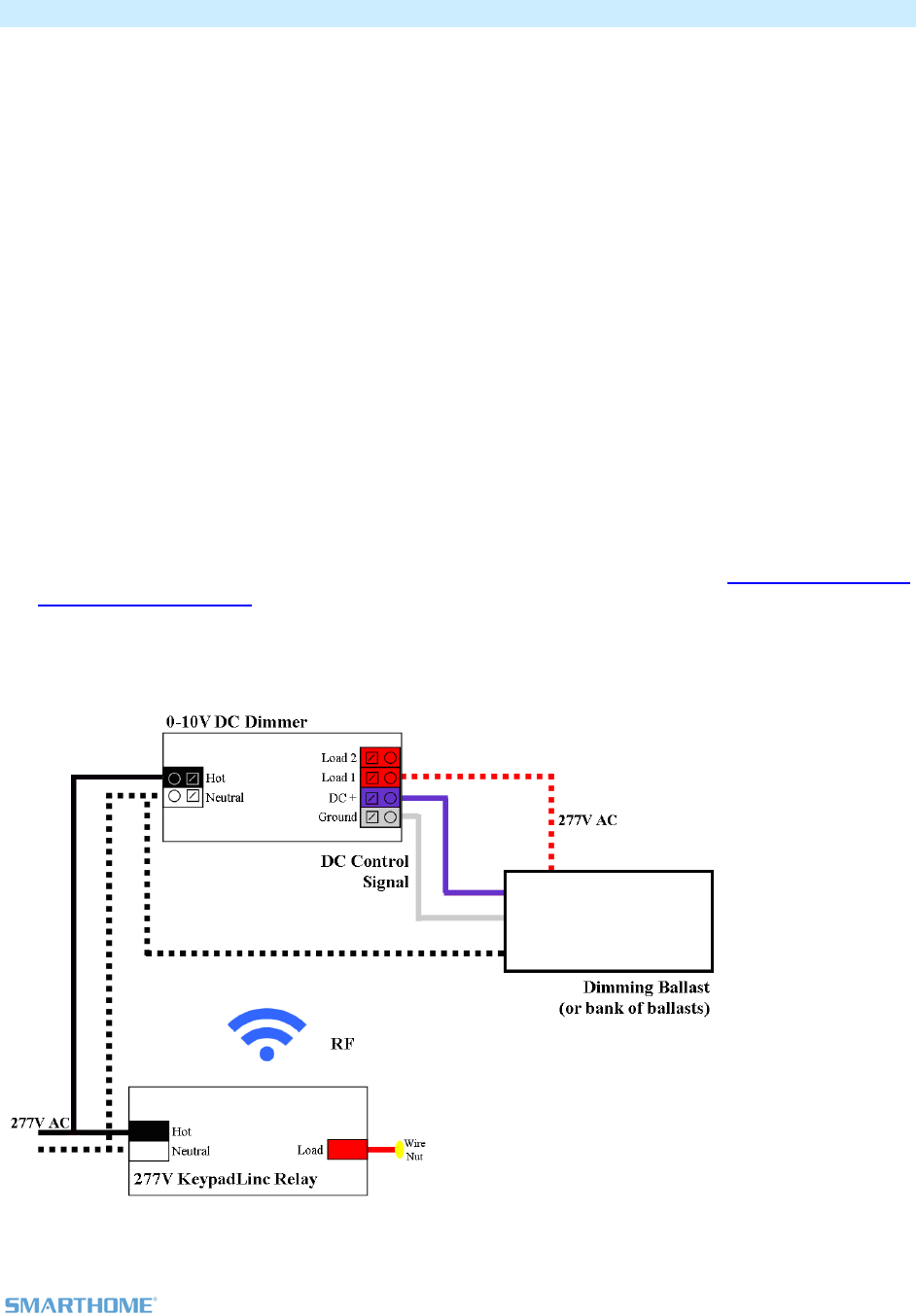
6) See the diagram below to identify and connect the LINE, LOAD, NEUTRAL DC(+) an
In-LineLinc. Be sure you have correctly identified the wires in the junction box
them
7) After you have connected all the wires, ensure that the wire co
there is no exposed copper except for the GROUND wire
8) Prior to reinstalling t
LineLinc
9) Use the On and Off button on In-Lin
a Scene as a Responder.
11) Gently place In-LineLinc into the fixture box, making sure nothing could accidentally press on the
buttons on its face
12) Reinstall the fixture
Page 6 of 12 2475DA2 Rev: 11/10/2011 9:41 AM
Installing In-LineLinc in Dual Relay Mode
1) Be sure to write down the INSTEON ID and location of the fixture you’ll be controlling
ture, and then verify
need to install a KeypadLinc 277V Controller (model 2487s) at the wall box that originally
wire from the
e load and wire nut it
c and the In-LineLinc
sure that
RAL wires on In-
ore connecting them.
nnectors are firmly attached and that
he fixture, turn on circuit breaker supplying power to the KeypadLinc and In-
nd Off button on In-LineLinc to test that it is controlling the load
10) Link In-LineLinc to the KeypadLinc or any other desired INSTEON devices. See Adding In-LineLinc to
2) At the circuit breaker or fuse panel, disable the circuit supplying power to the fix
the power is off
3) You will
controlled the fixture. Wire the KeypadLinc to line and Neutral but cap the red Load
KeypadLinc.
4) Take the existing switch leg from the wall box that supplied switched power to th
with the line on the KeypadLinc. This supplies constant HOT to both KeypadLin
at the same time
5) At the Ballast location, disconnect the wires from the fixture you will be controlling and en
you have ½ inch of bare wire on the ends
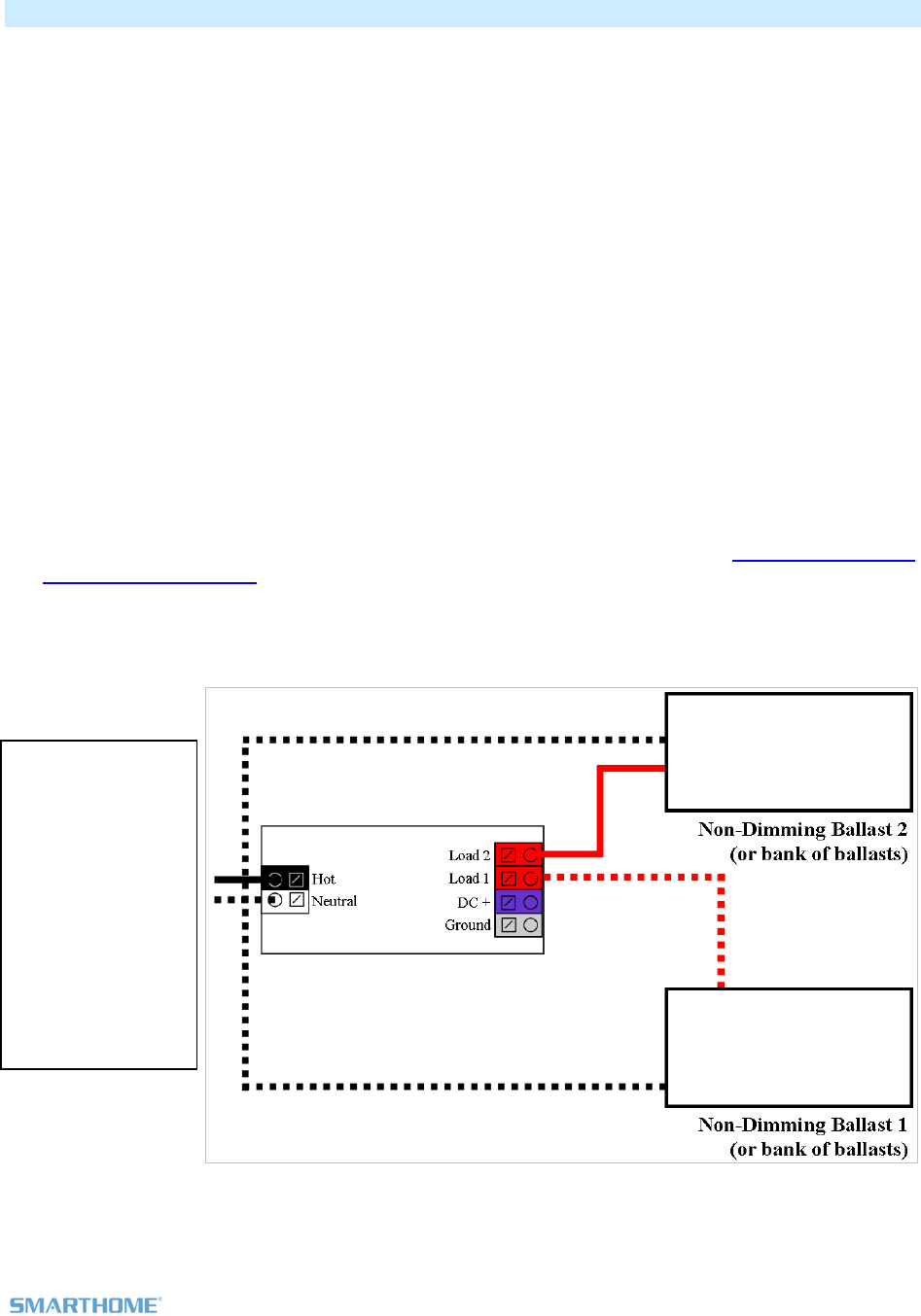
6) See the diagram below to identify and connect the LINE, LOAD1, LOAD 2 and NEUT
LineLinc. Be sure you have correctly identified the wires in the junction box bef
7) After you have connected all the wires, ensure that the wire co
there is no exposed copper
8) Prior to reinstalling t
LineLinc
9) Use the On a
a Scene as a Responder.
11) Gently place In-LineLinc into the fixture box, making sure nothing could accidentally press on the
buttons on its face
13) Reinstall the fixture
Diagram showing
only the non-
dimming
connection to
ballast 1 and 2.
The Hot feeding
this circuit is
paralleled from the
Hot connection on
the KeypadLinc
keeping both
devices HOT at all
times
Page 7 of 12 2475DA2 Rev: 11/10/2011 9:41 AM
INSTEON Programming
Links made between devices are called Scenes. The Scenes can contain 1 or 100+ devices
Adding In-LineLinc to a Scene as a Responder
1) Use the On and Off button on In-LineLinc to set the load to the state you wish to activate from the
controller activates the scene, etc.)
2)
3) ouble-beeps
Controller will (Beep)-(Beep) and its LED will stop blinking
ing On then Off on the controller’s scene button
controller (turn it on if you wish it to be on when the
Press & hold the scene controller button until it beeps1
Press & hold the Set button on In-LineLinc until it d
In-LineLinc's Status LED will flash once and then turn on steady
2
4) Confirm that scene addition was successful by tapp
The In-LineLinc will respond appropriately
Removing In-LineLinc from a Scene as a Responder
very important that you remove it from all of its
scene elays.
ss & hold the controller’s scene button until controller beeps
3) eLinc until it double-beeps
The In-LineLinc Status LED will flash once and then turn on bright if the load if off or dim if the
4) Confirm that Unlinking was successful by tapping the button you just Unlinked from on the controller
If you are going to discontinue using In-LineLinc, it is
controllers. Otherwise, the controllers will retry commands repetitively, creating network d
1) Pre 3
2) Press & hold the controller’s scene button until controller beeps again3
Press & hold the Set button on In-Lin
load is on
In-LineLinc will no longer respond
Advanced Features
Us g In tion Mode)
s in your home (via communications with dual-band
device ridged via In-
LineLinc:
Mode by tapping the Set button on In-LineLinc four times quickly
Other dual-band devices' LEDs will illuminate at 100% brightness
2) Check the LED behavior of the “other” dual-band devices
- If the “other” dual-band device is blinking green4
i. it is within range and not on the same phase, proceed to next Step
in -LineLinc as a Phase Bridge ( hase Bridging DetecP
In-LineLinc automatically bridges the electrical phase
s on the “other phase”). Use the following procedure to confirm that phases are b
1) Start Phase Bridging Detection
In-LineLinc will begin (Beeping)
1 If the controller does not have a beeper, wait until its LED begins blinking
2 Most models
3 For devices without beepers hold until its LED begins blinking (this may take 10+ seconds)
4 Or is simply blinking for single colored LEDs. If the “other” dual-band device is a KeypadLinc Dual-Band, the 4 middle LEDs will blink.

Page 8 of 12 2475DA2 Rev: 11/10/2011 9:41 AM
- If they are not blinking green1
i. Try moving the “other” device, check other dual-band devices or begin
test from a different initiator
3)
g and LED returns to previous state
Other devices’ LEDs will stop blinking
Tap In-LineLinc’s Set Button
In-LineLinc will stop beepin
Restoring Power to In-LineLinc
n-volatile memory.
tings are saved in this non-volatile memory, they will not be lost in the event of a power
failure.
ally return the load to the state it had before power
In-LineLinc stores all of its settings, such as links to other INSTEON devices, with no
Because set
In the event of a power loss In-LineLinc will automatic
was interrupted.
Resetting In-LineLinc to its Factory Default Settings
The factory reset procedure clears all settings from In-LineLinc, including INSTEON links, X10 addresses,
.etc
Option 1
1) ossible, remove all scene mIf p emberships prior to performing the factory reset.
3) Press & hold the In-LineLinc’s Set button until it beeps again
In-LineLinc’s LED will blink red
t button, then immediately press & hold it until the long beep stops
Option 2 –
2) ss & hold the Set button on In-LinPre eLinc until it beeps
LED will blink green
4) Double-tap the Se
In-LineLinc’s LED will turn off
In-LineLinc will emit a long ((((((Beep))))))
two people required
1) If possible, remove all scene memberships prior to performing the factory reset.
3) While Pressing & holding In-LineLinc’s Set button, have a friend turn the circuit breaker back on
As you continue to press & hold, In-LineLinc will (Beep)
4) Continue to press & hold the Set button for 3 seconds, then release
As soon as you release the Set button, the In-LineLinc LED will turn on solid green and
then dim. After a few seconds, In-LineLinc will (Beep)-(Beep).
2) Turn circuit breaker off
1 Or are not blinking at all for single colored LEDs. If the “other” dual-band device is a KeypadLinc, any LEDs that are on will go to full bright.
Page 9 of 12 2475DA2 Rev: 11/10/2011 9:41 AM
Specifications
General
Product Name -LineLinc Relay – INSTEON Remote Control In-Line On/Off
al-Band)
In
Switch (Du
Brand rthome Sma
Manufacturer Product Number 2475SDB
UPC 813922011425
FCC ID 773 SBP4
Patent Number 7,345,998 US, International Patents Pending
Warranty 2 Years, Limited
INSTEON
INSTEON ID 1
INSTEON 256 responder groups & 1 controller group
Maximum Scene Links 417
Scene Commands Supported
On Off
as
Responder
Software Configurable Yes, Always
RF Range 150’ Open air
X10 Support Yes
X10 Addresses 1 max, unassigned by default
INSTEON Device Category 0x02
INSTEON Device Subcategory 0x1F
INSTEON Product Key (IPK) 0x000085
Mechanical
Mounting Mounts inside lighting ballast box in the ceiling or in the wall
Wires
Colors:
White – Neutral 18 gauge
gauge
Violet – DCV(+) 18 gauge
Grey – DCV(-) 18 gauge
Black – Hot 18 gauge
Red – Load 1 18 gauge
Red w/tracer – Load 2 18
Set Button 1
Beeper Yes
LED Green/Red
Dimensions 171mm (wide), 30mm (high), 35mm (deep)
6.75-in. (wide), 1.2-in. (high), 2.4-in. (deep)
Weight 5.1 ounces
Operating Environment Indoors

Page 10 of 12 2475DA2 Rev: 11/10/2011 9:41 AM
Operating Temperature Range rees Fahrenheit 40 - 132 deg
Operating Humidity Range 0-85% Relative Humidity
Electrical
Voltage 100VAC to 277VAC (0-10VDC Dimmer)
Frequency Supports 50 Hz / 60 Hz dedicated for international and US use
Maximum Load Output lines (0-10VDC, Load 1 (277VAC / 5A), and load 2
(277VAC / 5A))
Load Type(s) Wired in ballasted dimming and non-dimming lighting loads
Retains all settings without po on-volatile EEPROM wer Yes, all saved in N
Standby power consumption < 1 watt
Safety Approved ETL (Intertek Testing Services)
Certifications FCC, IC Canada
Page 11 of 12 2475DA2 Rev: 11/10/2011 9:41 AM
Tro hootinubles g
Problem Possible C ution ause Sol
Make sure the circuit breaker is turned on.
The Status LED
LineLi
o
nc is not turning
on and won’t con
the load.
Check the junction box wires to ensure all
no bare wires are
n In-
trol
In-LineLinc may
getting power.
not be
connections are tight and
exposed.
The controller might have
king In-Line oller.
been reset witho
Unlin
ut
Linc from Re-Link In-LineLinc to the contr
it.
The INSTEO
be too weak.
N signal may Add additional INSTEON devices or move around
existing INSTEON devices. All INSTEON devices
aters. act as INSTEON network repe
Large applianc
refrigerator
conditioners
producing electri
on the powe
es
s or air
, may be
cal noise
r line.
, such as
In-LineLinc won’t
or work with a
controller.
l d
mpute
o
b
sig
1626-10) to filter
nal attenuation.
link
Other electrica
such as co
televisions, or p
strips, may be a
the INSTEON
evices,
rs,
wer
electrical noise and minimize si
sorbing
nal.
Install a power line noise filter (#
g
Unlink any unused responders from the controlle
HINT: If you are using home aut
you can easily c
r.
omation software,
heck scene membership and
eliminate unnecessary links.
In-LineLinc is tak
a
an
sponder that is
longer in use. Commands
re
t
down the
rm a factory reset
ing a
The controller m
sending comm
re
long time to respond
to a controller.
y be
ds to a
no
for the unused
are being resen
loading
sponder
and
signal.
If the above doesn’t work, perfo
on the controller.
The load turned on by
itself.
Another controller or timer
could have trigge e Resetting In-LineLinc
gs.
red In- Perform a factory reset. Se
to its Factory Default Settin
LineLinc.
The controller can
off In-LineLinc but In-
command from the
controller.
Re-link In-LineLinc to the controller, while the load
ontroller to In-
LineLinc.
turn
LineLinc does not turn
on when I send an ON
In-LineLinc may be linked
at its off state. is on. See Linking an INSTEON C
Temporarily remove power from In-LineLinc,
usually by opening the breaker feeding it.
In-LineLinc is locked
up.
A surge or excessive
noise on the power line
may have glitched it. If the above doesn’t work, perform a factory reset.
See Resetting In-LineLinc to its Factory Default
Settings.
If you have tried these solutions, reviewed this Installation and Programming Guide, and still cannot
resolve an issue you are having with In-LineLinc, please call:
The INSTEON Gold Support Line
800-762-7845

Page 12 of 12 2475DA2 Rev: 11/10/2011 9:41 AM
Certification and Warranty
Certification
This product has been thoroughly tested by ITS ETL SEMKO, a nationally recognized independent third-party testing laboratory. The North American
ETL Listed mark signifies that the device has been tested to and has met the requirements of a widely recognized consensus of U.S. and Canadian
ogram of quarterly factory follow-device safety standards, that the manufacturing site has been audited, and that the manufacturer has agreed to a pr
up inspections to verify continued conformance.
FCC & Industry Canada Compliance Statement
This device complies with FCC Rules Part 15 and Industry Canada RSS-210 (Rev. 8). Operation is subject to the following tw
(1) This d
o conditions:
evice may not cause harmful interference, and
rence, including interference that may cause undesired operation of the device.
L ation est autorise aux deux
ble d'en compromettre le
for a Class B digital device, pursuant to Part 15.107 and 15.109
l interference in residential installations. This equipment
ctions, may cause harmful
r installation. If this device
nterference, which can be verified by turning the device off and on, the user is encouraged to eliminate the interference by one or
ollowing measures:
void the user’s authority to
Warranty
(2) This device must accept any interfe
e present appareil est conforme aux CNR d'Industrie Canada applicables aux appareils radio exempts de licence. L'exploit
conditions suivantes:
(1) l'appareil ne doit pas produire de brouillage, et
(2) l'utilisateur de l'appareil doit accepter tout brouillage radiolectrique subi, mme si le brouillage est suscepti
fonctionnement.
The digital circuitry of this device has been tested and found to comply with the limits
of the FCC Rules. These limits are designed to provide reasonable protection against harmfu
ge ergy and, if not installed and used in accordance with the instru
interference to radio and television reception. However, there is no guarantee that interference will not occur in a particula
does cause such i
nerates, uses, and can radiate radio frequency en
more of the f
- Re-orient or relocate the receiving antenna of the device experiencing the interference
- Increase the distance between this device and the receiver
- Connect the device to an AC outlet on a circuit different from the one that supplies power to the receiver
- Consult the dealer or an experienced radio/TV technician
WARNING: Changes or modifications to this device not expressly approved by the party responsible for compliance could
operate the equipment.
Limited
ts to the original consumer purchaser of this product that, for a period of two years from the date of purchase, this product will be free
material and workmanship and will perform in substantial conformity to the description of the product in this Owner’s Manual. This
t apply to defects or errors caused by misuse or neglect. If the product is found to be defective in material or workmanship, or if the
does not perform as warranted above during the warranty period, Seller will either repair it, replace it, or refund the purchase price, at its
ation of the defect or error.
his product. For repair or
n # of the device to receive
Seller warran
from defects in
warranty shall no
product
option, upon receipt of the product at the address below, postage prepaid, with proof of the date of purchase and an explan
The repair, replacement, or refund that is provided for above shall be the full extent of Seller’s liability with respect to t
replacement during the warranty period, call the INSTEON Gold Support Line at 800-762-7845 with the Model # and Revisio
an RMA# and send the product, along with all other required materials to:
Smarthome
ATTN: Receiving
16542 Millikan Ave.
Irvine, CA 92606-5027
Limitations
The above warranty is in lieu of and Seller disclaims all other warranties, whether oral or written, express or implied, including any warranty or
merchantability or fitness for a particular purpose. Any implied warranty, including any warranty of merchantability or fitness for a particular purpose,
which may not be disclaimed or supplanted as provided above shall be limited to the two-year of the express warranty above. No other representation
or claim of any nature by any person shall be binding upon Seller or modify the terms of the above warranty and disclaimer.
Home automation devices have the risk of failure to operate, incorrect operation, or electrical or mechanical tampering. For optimal use, manually verify
the device state. Any home automation device should be viewed as a convenience, but not as a sole method for controlling your home.
In no event shall Seller be liable for special, incidental, consequential, or other damages resulting from possession or use of this device, including
without limitation damage to property and, to the extent permitted by law, personal injury, even if Seller knew or should have known of the possibility of
such damages. Some states do not allow limitations on how long an implied warranty lasts and/or the exclusion or limitation of damages, in which case
the above limitations and/or exclusions may not apply to you. You may also have other legal rights that may vary from state to state.
U.S Patent No. 7,345,998, International patents pending
© Copyright 2011 Smarthome, 16542 Millikan Ave., Irvine, CA 92606, 800-762-7845, www.smarthome.com