SmartLabs 2475F In-Line Fan and Light Controller User Manual 2475F FanLinc Manual 20111207
SmartLabs, Inc. In-Line Fan and Light Controller 2475F FanLinc Manual 20111207
Users Manual
Page 1 of 13 Rev: 12/7/2011 3:09 PM
FanLinc
Owners Manual
INSTEON
®
Remote Control Light & Fan Controller (Dual-Band) (#2475F)

Page 2 of 13 Rev: 12/7/2011 3:09 PM
About FanLinc .............................................................................................................................................3
Features & Benefits .................................................................................................................................... 3
What’s in the Box?..................................................................................................................................... 3
Optional Accessories.................................................................................................................................4
Installation ................................................................................................................................................... 4
Identifying the Electrical Wires in your Home............................................................................................ 4
INSTEON Scenes......................................................................................................................................... 6
Add FanLinc’s Light to a Scene as a Responder ......................................................................................6
Add FanLinc’s Fan to a Scene as a Responder........................................................................................ 6
Remove FanLinc from a Scene.................................................................................................................7
LED and Beeper Behavior ..........................................................................................................................8
LEDs .......................................................................................................................................................... 8
Beeper ....................................................................................................................................................... 8
Advanced Features .....................................................................................................................................8
Using FanLinc as a Phase Bridge ............................................................................................................. 9
Returning FanLinc to Factory Default Settings..........................................................................................9
X10 Programming ..................................................................................................................................... 10
Specifications ............................................................................................................................................ 10
Troubleshooting ........................................................................................................................................ 12
CERTIFICATION, AND WARRANTY ........................................................................................................ 13
Certification.............................................................................................................................................. 13
FCC & Industry Canada Compliance Statement..................................................................................... 13
Limited Warranty ..................................................................................................................................... 13
Limitations ............................................................................................................................................ 13
Page 3 of 13 Rev: 12/7/2011 3:09 PM
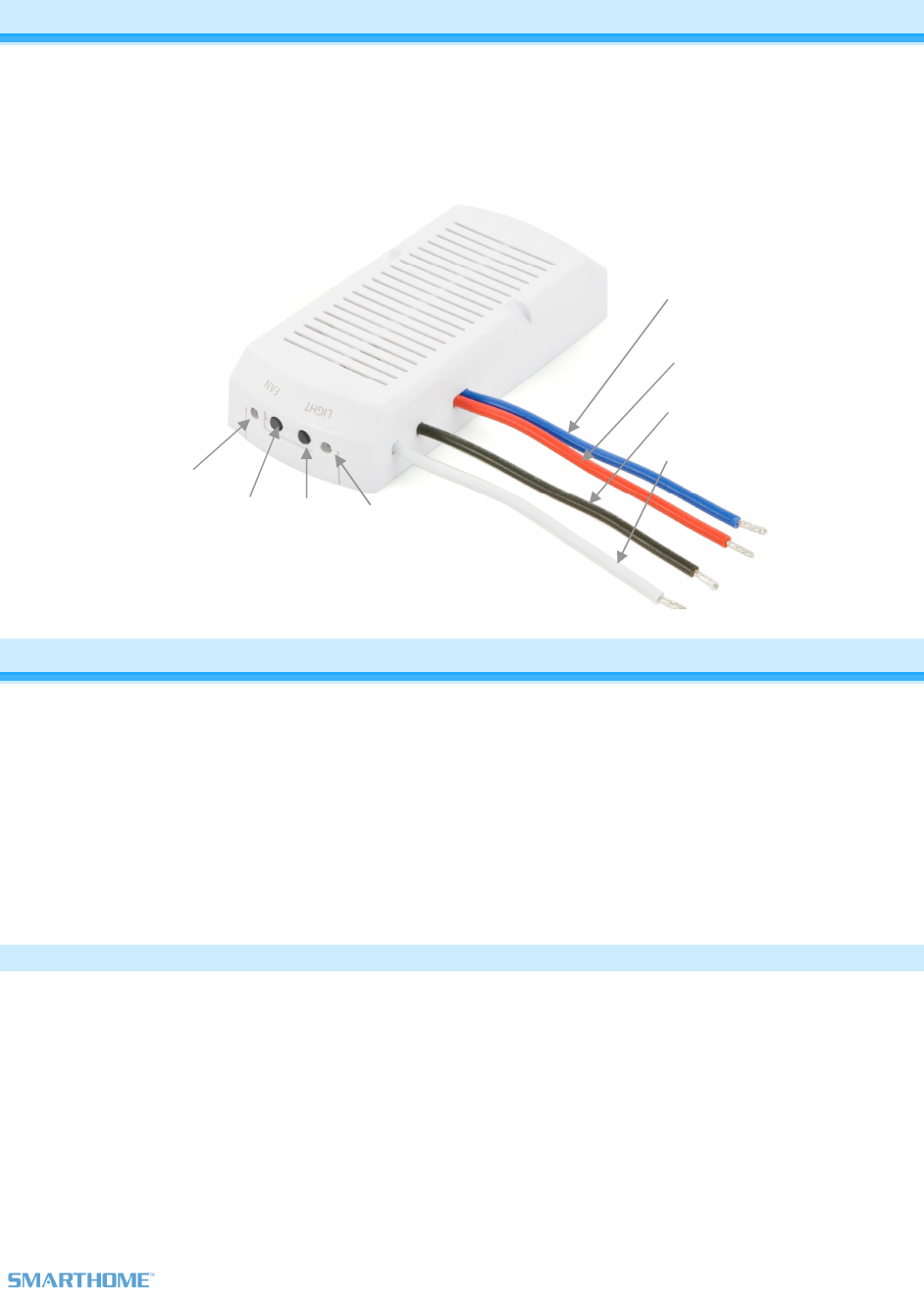
Lights (Blue)
Neutral
LINE
Fan (Red)
Fan
Status
LED Set
Button
(Fan)
Set
Button
(Lights)
Light
Status
LED
About FanLinc
FanLinc is designed to easily incorporate both fan speed and light control within your INSTEON network.
It is a dual-load responder simultaneously acting as a light fixture dimmer plus a 4 speed fan controller
(Off, Low, Medium & High).
The solution is to pair FanLinc (installed in fan cowling or junction box above fan) with controllers such as
KeypadLinc, RemoteLinc 2, software and other controllers.
Features & Benefits
- 4 Speed Fan controller (Off, Low, Medium & High)
- 300 Watt Incandescent Dimmer
- Easy setup
- X10 Compatible (1 address for light, 1 address for fan)
- Dual-band – Acts as an Access Point and bridges phases
- Specially designed to fit inside most ceiling fan cowlings
- Dual Set Buttons and Dual LEDs for simple scene programming
- Beeper for setup ease
- All settings stored in stable memory which is maintained even without power
- 2 year Warranty
What’s in the Box?
- FanLinc
- Wire Nuts
- 1 Cable Tie
- Quick-Start Guide
Page 4 of 13 Rev: 12/7/2011 3:09 PM
Optional Accessories
Accessory Part # Link
KeypadLinc 2486D6
http://www.smarthome.com/2486DWH6.html
RemoteLinc 2440 http://www.smarthome.com/2440.html
RemoteLinc 2 2444A2WH4
2444A2WH8
http://www.smarthome.com/2444A2WH4.html
HouseLinc 2413UH, 2413SH http://www.smarthome.com/2413UH.html
SmartLinc 2412N http://www.smarthome.com/2412N.html
Installation
CAUTIONS AND WARNINGS
Read and understand these instructions before installing and retain them for future reference.
FanLinc is intended for installation in accordance with the National Electric Code and local regulations in the United States or the
Canadian Electrical Code and local regulations in Canada. Use indoors only. FanLinc is not designed nor approved for use on
power lines other than 120VAC, 50Hz / 60Hz, single phase. Attempting to use FanLinc on non-approved power lines may have
hazardous consequences.
• Use only indoors or in outdoor rated box
• Be sure that you have turned off the circuit breaker or removed the fuse for the circuit you are installing FanLinc in.
Installing FanLinc with the power on will expose you to dangerous voltages.
• Connect only copper or copper-clad wire to FanLinc
• FanLinc may feel warm during operation. The amount of heat generated is within approved limits and poses no
hazards. To minimize heat buildup, ensure that the area surrounding the FanLinc air vents is as clear of clutter as
possible.
• To reduce the risk of overheating and possible damage to other equipment, use FanLinc Load output to control no
more than 300 watts of 120VAC incandescent lamps plus no more than 1 Amp of Fan load. Dimming an inductive load
(by connecting to the Light load wire), such as a fan or transformer, could cause damage to the dimmer, the load
bearing device, or both. If the manufacturer of the load device does not recommend dimming, use a non-dimming
INSTEON on/off switch. USER ASSUMES ALL RISKS ASSOCIATED WITH DIMMING AN INDUCTIVE LOAD.
• You will need a flathead screwdriver, a phillips head screwdriver and a voltage meter to install FanLinc
Identifying the Electrical Wires in your Home
To install FanLinc, you will need to identify the following four wires:
• LINE - usually black, may also be called HOT or LIVE, carries 120VAC electricity into the outlet
• NEUTRAL - usually white
• LOAD – Usually Blue or Red
• GROUND - bare copper wire or metal fixture (if grounded)
If you are having difficulties identifying wires, consult an electrician to help you.
IMPORTANT!
If you are not knowledgeable about, and comfortable with, electrical circuitry, you should have a qualified electrician install this
device for you. If you have any questions, please consult an electrician.
Page 5 of 13 Rev: 12/7/2011 3:09 PM
1) Using your fan’s pull chains, turn light On and set fan to highest speed
NOTE: All fan and light controls will be done through FanLinc once
installed
2) Turn off the circuit breaker (or remove fuse) supplying power to the
fan’s location
3) Identify Line, Neutral and Load lines for light and fan separately
4) Remove the light and/or fan from the electrical box
5) Disconnect the wires from the ceiling fan and/or light
6) As necessary, strip ½ inch of insulation off the wire ends
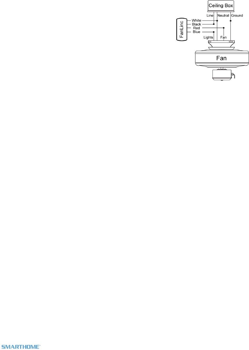
7) Connect FanLinc’s White wire and the fixture’s neutral wire to the
house NEUTRAL with a wire nut
8) Connect FanLinc’s Blue [light] wire to the fixture’s Light with a wire nut
9) Connect FanLinc’s Red [fan] wire to the fixture’s Fan with a wire nut
10) Connect FanLinc’s Black wire to LINE with a wire nut
11) Ensure all connections are solid, no exposed copper (other than ground)
12) Turn circuit breaker back on
FanLinc Set Light LED will be on Green (by default)
Fan LED will be on RED
13) To test Light, tap the Light Set Button
Light will toggle between Green (On) and Red (Off)
14) To test Fan, tap the Fan Set Button once
FanLinc will (Beep)
LED will blink Green
(Note: fan motor will not actually engage by tapping FanLinc buttons, only INSTEON
signals from a linked controller to FanLinc will activate the fan motor)
15) Tap Blue a 2
nd
time
FanLinc will (Beep)-(Beep)
LED will blink Green faster
16) Tap Blue a 3
rd
time
FanLinc will (Beep)-(Beep)-(Beep) very quickly
LED will blink Green faster still
17) Tap Blue a 4
th
time
LED will go on RED
IMPORTANT: SET UP ALL DESIRED MANUAL SCENE MANAGEMENT
BEFORE REPLACING COWLING AND RE-MOUNTING TO CEILING.
SEE “SETTING UP INSTEON SCENES”
18) Optional: Cover LED's with black electrical tape to avoid unwanted glowing at night which may be
visible in some fan cowlings
If using software and you program LED’s off, they remain on until you send a
FanLinc a fan command from an INSTEON controller
19) Carefully remount cowling with FanLinc inside (or in electrical box above). Certain installations may
require the use of a UL rated cable tie (included) to secure FanLinc to the fan bracket. Run cable tie
Page 6 of 13 Rev: 12/7/2011 3:09 PM
in the notches on the FanLinc case; ensure that cable tie and wires will not interfere with any moving
parts.
INSTEON Scenes
Scene: One or more INSTEON responders (like FanLinc) which respond to an INSTEON controller. When
the scene is activated (turned “on”), all devices return to the states they were at when the scene was
programmed.
INSTEON scenes let you activate dramatic lighting moods at the touch of a button. For example, you can
set all the lights in a scene to dim to 50% and have the ceiling fan spinning slowly, all with the tap of a
button on any INSTEON controller. INSTEON scenes are easy to set up, just follow the directions below.
Add FanLinc’s Light to a Scene as a Responder
Follow the steps below to add your light to an INSTEON scene.
1) Press & hold the scene controller button until it beeps
1
Controller’s LED will blink
2) Tap FanLinc’s Light Set button until the connected light is on
Light’s LED will be GREEN
3) Press & hold FanLinc’s Light Set button until FanLinc double-beeps
Light’s LED will flash once & return to GREEN
Controller will (Beep)-(Beep)
3
and its LED will stop blinking
4) Make sure the fan’s lights are connected to the assembly, confirm that the scene addition was
successful by tapping On / Off on your scene controller
The Light Connected to FanLinc will toggle between On and Off
5) If you wish to adjust the light’s scene On-Level and/or Ramp Rate
Adjusting Ramp Rate:
a. Using your Scene Controller, adjust the light’s brightness to correspond with the ramp
rate desired (Ramp Rates)
b. Double-Tap FanLinc’s Fan Set Button
c. Return to step #1 above
Adjusting On-Level:
a. Using your scene controller, adjust the light’s brightness to the desired brightness for
your scene
b. Return to Step #1
6) If you wish to add FanLinc’s light to more scenes, simply repeat these steps
Add FanLinc’s Fan to a Scene as a Responder
Follow the steps below to add your ceiling fan to an INSTEON scene.
1
If the controller does not have a beeper, wait until its LED begins blinking
3
Most models

Page 7 of 13 Rev: 12/7/2011 3:09 PM
1) Tap FanLinc’s Fan Set button until FanLinc’s Beeper & LED indicate the desired fan speed
NOTE: For your safety the fan will not spin when the Fan Set button is pressed, only incoming
INSTEON commands will initiate fan speed control.
Tap Fan Speed Beeper LED
1
st
Low
Single Beep Blinks Green Slow
2
nd
Medium Double Beep Blinks Green Medium
3
rd
High Fast Double Beep Blinks Green Fast
4
th
Off None Red
Fan’s LED will be in the desired state (see table above)
2) Press & hold the scene controller Set button until it beeps
1
Controller’s LED will blink
3) Press & hold FanLinc’s Fan Set button until FanLinc double-beeps
Fan’s LED will (Beep)-(Beep) and the LED will return to previous state.
Controller will (Beep)-(Beep)
1
and its LED will stop blinking
4) If you wish to add your fan to more scenes, simply repeat these steps
5) Temporarily hang the fan from the mounting ring so the fan can spin safely and without
obstruction. Then while safely clear of the fan blades press On / Off on your scene controller
Fan’s LED will toggle between Green scene state and RED (Off)
Remove FanLinc from a Scene
If you are going to discontinue using FanLinc, it is very important that you Un-link it from all of its scene
controllers. Otherwise, the controllers will retry commands repetitively, creating network delays. These
instructions remove FanLinc from a scene for which it is a responder. Whenever possible, use software
for managing links.
WARNING: Prior to proceeding, use the pull chain to turn the fan motor to Off.
1) Tap the button you wish to unlink. Press & hold the controller’s Set button until Controller beeps
2
Controller’s LED will blink
2) Press & hold the Set button until controller beeps again
1
Controller’s LED will continue blinking
3) If you wish to remove FanLinc’s Light from the scene – press & hold FanLinc’s Light Set button until
it double-beeps
Light’s LED will flash once & return to steady GREEN (or RED)
4) If you wish to remove FanLinc’s Fan from the scene – press & hold FanLinc’s Fan Set button until it
double-beeps
Fan’s LED will flash once & return to blinking GREEN (or steady RED)
Controller’s LED will stop blinking
1
Most models
2
For devices without beepers hold until its LED begins blinking (this may take 10+ seconds)
Page 8 of 13 Rev: 12/7/2011 3:09 PM
5) Temporarily hang the fan from the mounting ring so the fan can spin safely and without obstruction.
Then while safely clear of the fan blades press On / Off on your scene controller
6) Confirm that Unlinking was successful by tapping the button you just Unlinked from on the Controller
FanLinc’s LEDs, light and/or fan will no longer respond
NOTE: If you have a controller such as SwitchLinc linked to both the fan and light on FanLinc and you
unlink SwitchLinc from either fan or light, you must re-link to the other feature to have it continue to
control the other feature.
LED and Beeper Behavior
LEDs
Fan LED
Green blink slow Setup: Set scene speed to Slow
Green blink medium Setup: Set scene speed to Medium
Green blink fast Setup: Set scene speed to Fast
Red steady on Setup: Set scene speed to Off
Green steady on Fan is On
Red steady on Fan is Off
Light LED
Blinking Green Setup: Awaiting X10 address
Blinking Red Setup: Awaiting X10 address removal
Green Light is On
Red Light is Off
Beeper
Beeper
Single Beep Enter Setup Mode (or transition to next Setup Mode)
Double-Beep Setup successful, return to Ready Mode
3 Second Beep Return to Ready Mode (either after setup time-out or user-
initiated Set Button Tap)
Fast Beeps On transition to next fan speed
Advanced Features
The following settings are available for programming only via compatible software:

Page 9 of 13 Rev: 12/7/2011 3:09 PM
o Enable/Disable LEDs
o LED Blink on traffic
o Programming Lock
Using FanLinc as a Phase Bridge
FanLinc automatically bridges phases in your home (via communications with dual-band devices on the
“other phase”). Use the following procedure to confirm that the phases have been bridged:
1)
Start Phase Bridging Detection Mode by tapping the Light Set button on FanLinc four times quickly
FanLinc will begin (Beeping) and its LED will turn steady GREEN
2)
Check the LED behavior of the “other” dual-band devices. If they are not blinking, try moving the
“other” device.
3)
If the LED on the “other” dual-band device is blinking, the devices are within range and on opposite
phases. Tap FanLinc’s Light Set Button to exit Phase Bridging Detection Mode.
LED will return to GREEN
if light is on, or turn RED if light is OFF
Note: If the FanLinc is being phase-bridged, its LED status will be:
RED = same phase / GREEN = opposite phase
Returning FanLinc to Factory Default Settings
NOTE: All Settings and Scenes will be erased.
Option 1
1) If possible, remove all scene memberships prior to performing the factory reset (see Remove
FanLinc from a Scene above)
2) Press & hold the Light Set button on FanLinc until it beeps
LED will blink GREEN
3) Press & hold the FanLinc’s Light Set button until it beeps again
FanLinc’s LED will blink RED
4) Double-tap the Light Set button,
Both FanLinc’s LEDs and the fan light will turn off
FanLinc will (Beep)
5) Within 1 second, press & hold the Fanlinc’s Light Set button releasing after the long beep stops
(>5 seconds)
FanLinc will emit a long, continuous ((((((Beep)))))) for >5 seconds
As soon as you release the Light Set button, the FanLinc LED will turn on solid green and
then turn off. After a few seconds, FanLinc will (Beep)-(Beep) and the LED will turn
GREEN and the fan light will turn on
Option 2
Page 10 of 13 Rev: 12/7/2011 3:09 PM
1) If possible, remove all scene memberships prior to performing the factory reset (see Remove
FanLinc from a Scene above)
2) Turn circuit breaker Off
3) While Pressing & holding FanLinc’s Light Set button, have a friend turn circuit breaker back on
As you continue to press & hold, FanLinc will emit a long continuous (((((Beep)))))
4) Continue to press & hold the Light Set button for >5 seconds, release when beeping stops
As soon as you release the Light Set button, the FanLinc LED will turn on solid green and
then turn off. After a few seconds, FanLinc will (Beep)-(Beep) and the LED will turn
GREEN and the Fan light will turn on
X10 Programming
Instructions on setting X10 primary address can be found online:
http://www.smarthome.com/insteon-x10-programming.html
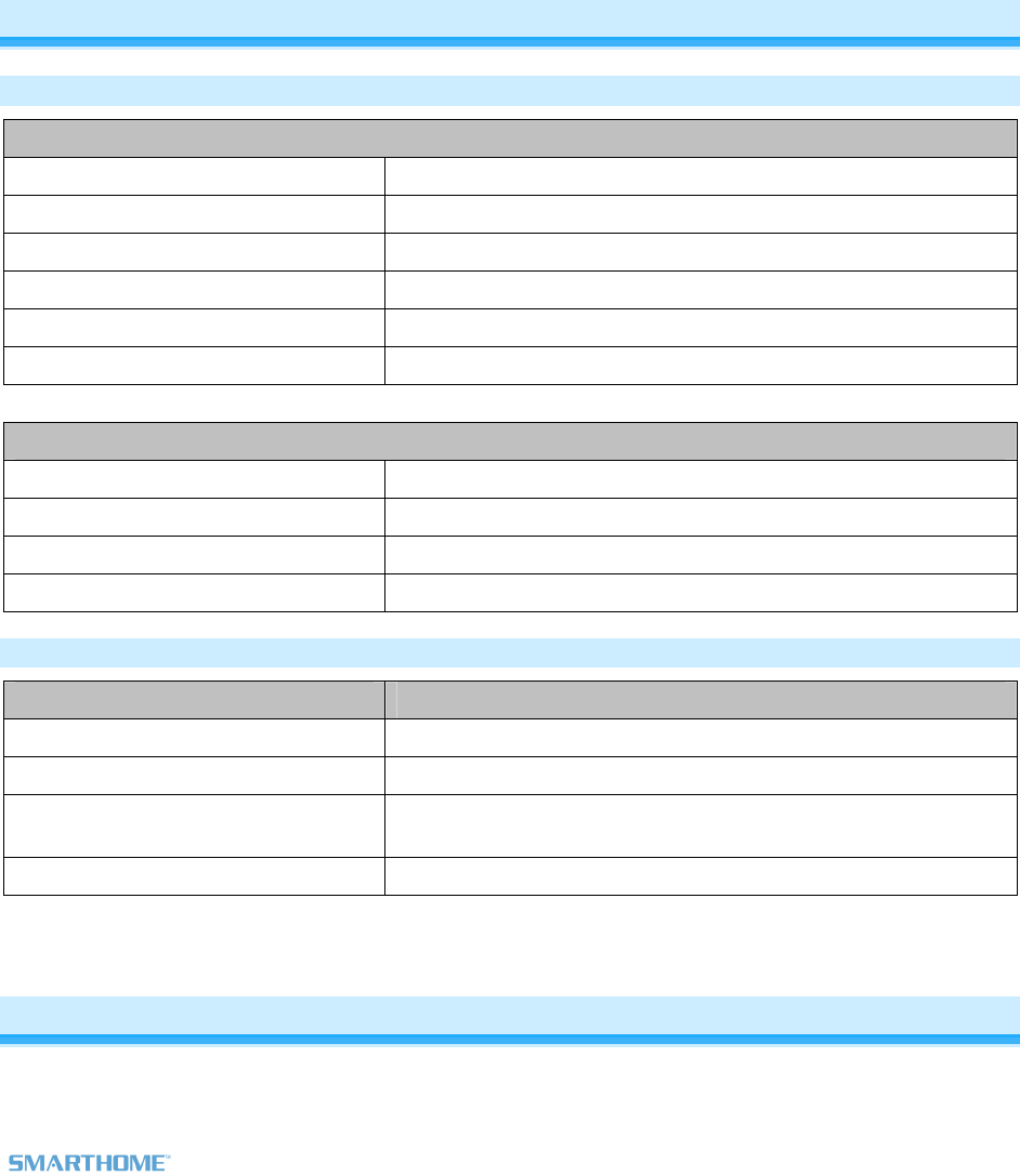
Specifications
General
Product Name FanLinc – INSTEON In-Line, Dual-Load Module
Brand Smarthome
Manufacturer Product Number 2475F
UPC 813922011548
FCC ID SBP2475F
Patent Number 7,345,998 US, International Patents Pending
Warranty 2 Years, Limited
INSTEON
INSTEON ID 1
Scenes 2 Responder Groups
Maximum Scene Links 400
On Off
Brighten Dim
Scene Commands Supported
Fast On Fast Off
Software Configurable Yes
RF Range > 150’ Open Air
X10 Support Yes
X10 Addresses 2 max
Beeper Yes
Page 11 of 13 Rev: 12/7/2011 3:09 PM
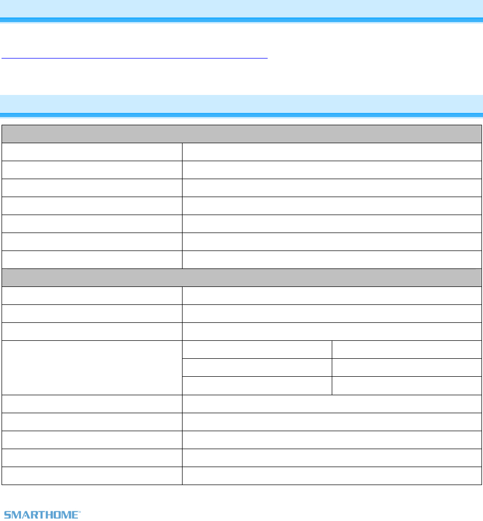
Operation
Light Dimmer Fan Controller
INSTEON Scene/Group 1 INSTEON Scene/Group 2
X10
Brightness Levels 32 Fan Speeds 4 (Off, Slow, Medium &
Fast)
Dimmer Control On, Off, Fast On, Fast
Off and Dim / Brights +
X10 commands
Fan Control On, Off, Fast On, Fast
Off and Dim / Brights +
X10 commands
Brightness =:
- Off
- 1% - 49%
- 50% - 99%
- 100%
Fan is:
- Off
- Slow
- Medium
- Fast
LED Dual Color, Green &
Red
LED Dual Color, Green & Red
LED Green = ON
Red = Off
Setup = Varies
LED Green = ON
Red = Off
Setup = Varies
Set Button Black Set Button Black
X10 1 Address, unassigned
by default
X10 1 Address, unassigned
by default
Mechanical
Wires 4, 16 gauge
Wires Black – Hot / Line
Blue – Light Load
Red – Fan Load
White - Neutral
Case Color White
Plastic UV Stabilized ABS
Dimensions 66.46mm L x 33.017mm W – 9.75mm D
Weight 22g (0.05 lb)
Operating Environment Indoors
Electrical
Retains all settings without power Yes, all saved in Non-volatile EEPROM
Voltage 120VAC, Single Phase
Frequency 50/60Hz
Maximum Dimmer Load 300 Watts
Page 12 of 13 Rev: 12/7/2011 3:09 PM
Maximum Fan Load 1 Amp
Safety Approved ETL
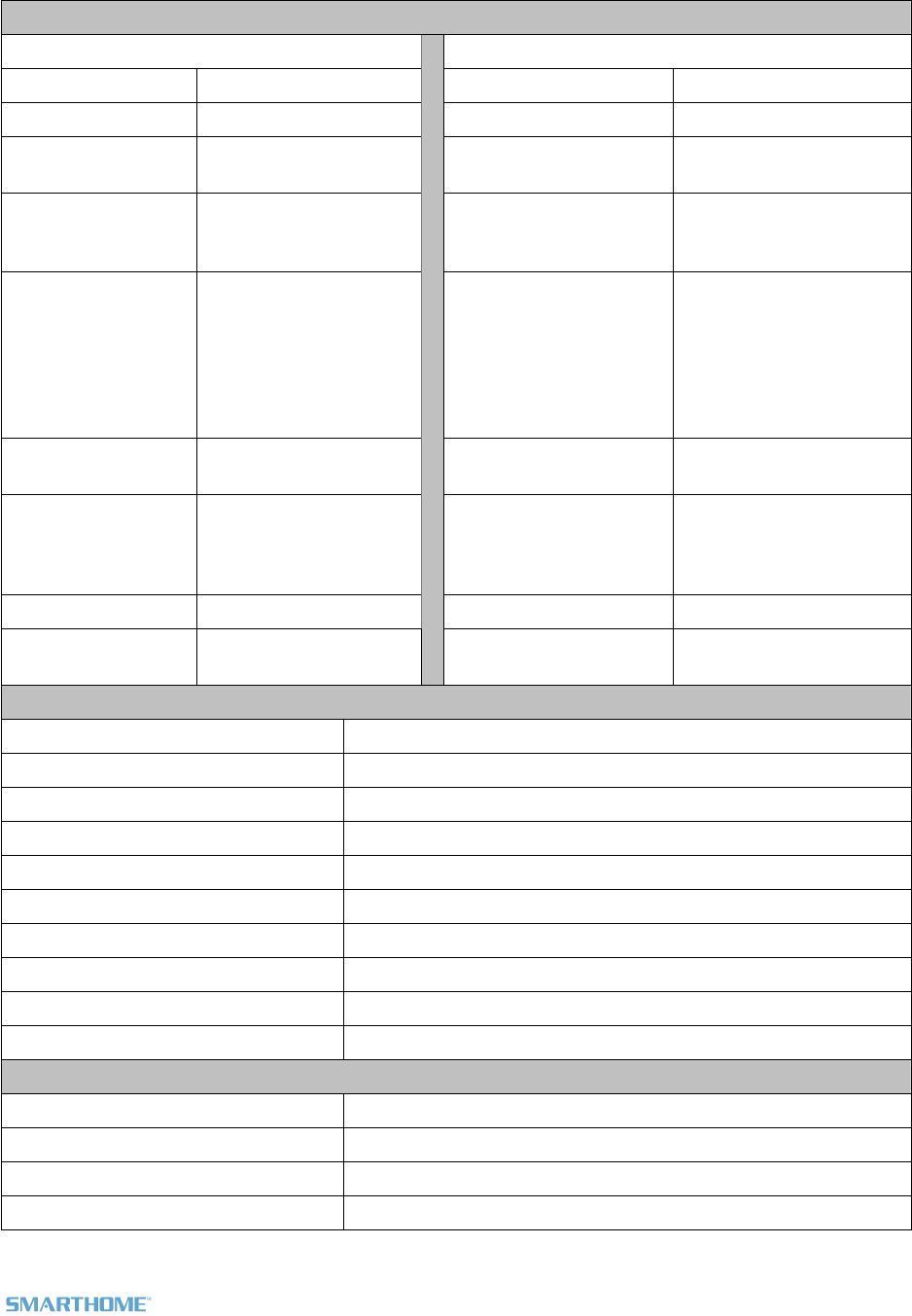
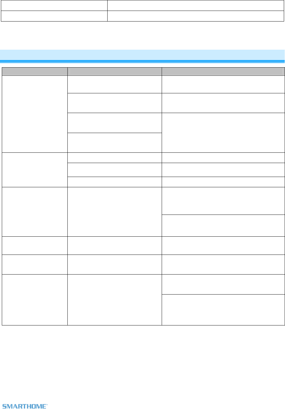
Troubleshooting
Problem Possible Cause Solution
FanLinc may be out of range Try moving an Access Point or other plug-in module
closer to FanLinc
The INSTEON signal may not be
getting to the “vicinity” of Responder
Make sure phases are bridged, Add additional
INSTEON devices and/or move around existing
INSTEON devices
Large appliances, such as refrigerators
or air conditioners, may be producing
electrical noise on the power line
FanLinc won’t add as a
scene responder
Other electrical devices, such as
computers, televisions, or power strips,
may be absorbing the INSTEON signal
Install a power line noise filter (e.g. #1626-10) to
filter electrical noise and minimize signal attenuation
Ramp Rate may be Extremely Slow
Add to scene again, with fast Ramp Rate
Pull chain on fan light is not in “ON”
position Use pull chain to turn light on
FanLinc will not turn on
light
Controller may be Linked at OFF Add to scene again, at desired brightness
Remove all unused Responders from the Controller.
HINT: If you are using HouseLinc software, you can
easily check scene membership and eliminate
unnecessary Links
FanLinc is taking a long
time to respond to scene
triggers
Controller may be sending commands
to a Responder(s) that is no longer in
use
If the above doesn’t work, perform a factory reset
on the Controller
Fan speed is too slow or
does not turn on Pull chain on fan is not set to HIGH Use pull chain to set fan to highest speed setting
The light is buzzing when
on or dim.
The light dimming component inside
FanLinc “chops” the power line sine
wave to reduce the power.
The bulb filaments are vibrating. Use rough-service,
130 Volt, or appliance-grade bulbs to reduce the
noise.
Power cycle: Turn appropriate circuit breaker Off,
wait 10 seconds and turn back on
FanLinc is no longer
responding. Glitch
Perform a factory reset on FanLinc and set up links
again
If you have tried these solutions, reviewed this Owner’s Manual, and still cannot resolve an issue you are having with
FanLinc, please call: 800-762-7845
Page 13 of 13 Rev: 12/7/2011 3:09 PM
CERTIFICATION, AND WARRANTY
Certification
This product has been thoroughly tested by ITS ETL SEMKO, a nationally recognized independent third-party testing laboratory. The North American
ETL Listed mark signifies that the device has been tested to and has met the requirements of a widely recognized consensus of U.S. and Canadian
device safety standards, that the manufacturing site has been audited, and that the manufacturer has agreed to a program of quarterly factory follow-
up inspections to verify continued conformance.
FCC & Industry Canada Compliance Statement
This device complies with FCC Rules Part 15 and Industry Canada RSS-210. Operation is subject to the following two conditions:
(1) This device may not cause harmful interference, and
(2) This device must accept any interference, including interference that may cause undesired operation of the device.
Le present appareil est conforme aux CNR d'Industrie Canada applicables aux appareils radio exempts de licence. L'exploitation est autorise aux deux
conditions suivantes:
(1) l'appareil ne doit pas produire de brouillage, et
(2) l'utilisateur de l'appareil doit accepter tout brouillage radiolectrique subi, mme si le brouillage est susceptible d'en compromettre le
fonctionnement.
The digital circuitry of this device has been tested and found to comply with the limits for a Class B digital device, pursuant to Part 15 of the FCC Rules.
These limits are designed to provide reasonable protection against harmful interference in residential installations. This equipment generates, uses,
and can radiate radio frequency energy and, if not installed and used in accordance with the instructions, may cause harmful interference to radio and
television reception. However, there is no guarantee that interference will not occur in a particular installation. If this device does cause such
interference, which can be verified by turning the device off and on, the user is encouraged to eliminate the interference by one or more of the following
measures:
- Re-orient or relocate the receiving antenna of the device experiencing the interference
- Increase the distance between this device and the receiver
- Connect the device to an AC outlet on a circuit different from the one that supplies power to the receiver
- Consult the dealer or an experienced radio/TV technician
WARNING: Changes or modifications to this device not expressly approved by the party responsible for compliance could void the user’s authority to
operate the equipment.
Limited Warranty
Seller warrants to the original consumer purchaser of this product that, for a period of two years from the date of purchase, this product will be free
from defects in material and workmanship and will perform in substantial conformity to the description of the product in this Owner’s Manual. This
warranty shall not apply to defects or errors caused by misuse or neglect. If the product is found to be defective in material or workmanship, or if the
product does not perform as warranted above during the warranty period, Seller will either repair it, replace it, or refund the purchase price, at its
option, upon receipt of the product at the address below, postage prepaid, with proof of the date of purchase and an explanation of the defect or error.
The repair, replacement, or refund that is provided for above shall be the full extent of Seller’s liability with respect to this product. For repair or
replacement during the warranty period, call the INSTEON Gold Support Line at 800-762-7845 with the Model # and Revision # of the device to receive
an RMA# and send the product, along with all other required materials to:
Smarthome
ATTN: Receiving
16542 Millikan Ave.
Irvine, CA 92606-5027
Limitations
The above warranty is in lieu of and Seller disclaims all other warranties, whether oral or written, express or implied, including any warranty or
merchantability or fitness for a particular purpose. Any implied warranty, including any warranty of merchantability or fitness for a particular purpose,
which may not be disclaimed or supplanted as provided above shall be limited to the two-year of the express warranty above. No other representation
or claim of any nature by any person shall be binding upon Seller or modify the terms of the above warranty and disclaimer.
Home automation devices have the risk of failure to operate, incorrect operation, or electrical or mechanical tampering. For optimal use, manually verify
the device state. Any home automation device should be viewed as a convenience, but not as a sole method for controlling your home.
In no event shall Seller be liable for special, incidental, consequential, or other damages resulting from possession or use of this device, including
without limitation damage to property and, to the extent permitted by law, personal injury, even if Seller knew or should have known of the possibility of
such damages. Some states do not allow limitations on how long an implied warranty lasts and/or the exclusion or limitation of damages, in which case
the above limitations and/or exclusions may not apply to you. You may also have other legal rights that may vary from state to state.
U.S Patent No. 7,345,998, International patents pending
© Copyright 2011 Smarthome, 16542 Millikan Ave., Irvine, CA 92606, 800-762-7845, www.smarthome.com