SmartLabs 2477SA Dual-Band Load Controller with Phase Coupler User Manual 2477SA QSG 20100202
SmartLabs, Inc. Dual-Band Load Controller with Phase Coupler 2477SA QSG 20100202
Users Manual
Page 1 of 2
Rev. 02-02-2010
SmartLabs Limited Warranty – SmartLabs warrants to original consumer of this product for a period of 2 years from date of purchase, this product will be
free from defects in material & workmanship & will perform in substantial conformity with its Owner's Manual. Warranty shall not apply to defects caused by
misuse or neglect.
U.S. Patent No. 7,345,998, International patents pending © Copyright 2010
SmartLabs, 16542 Millikan Ave., Irvine, CA 92606, 1-800-SMARTHOME
(
800-762-7846
)
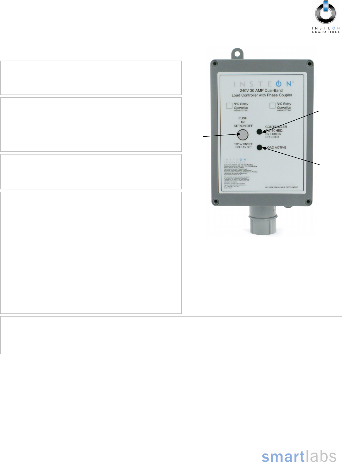
Set
button
Installation
1) At the circuit breaker or fuse panel, disable the circuit supplying
power to the electrical junction box that is wired to the appliance
you wish to control with 240V Load Controller
2) Remove the cover of the junction box and disconnect the two
supply lines coming from the circuit breaker, ensuring that you
have ½” bare and clean copper wire on the ends.
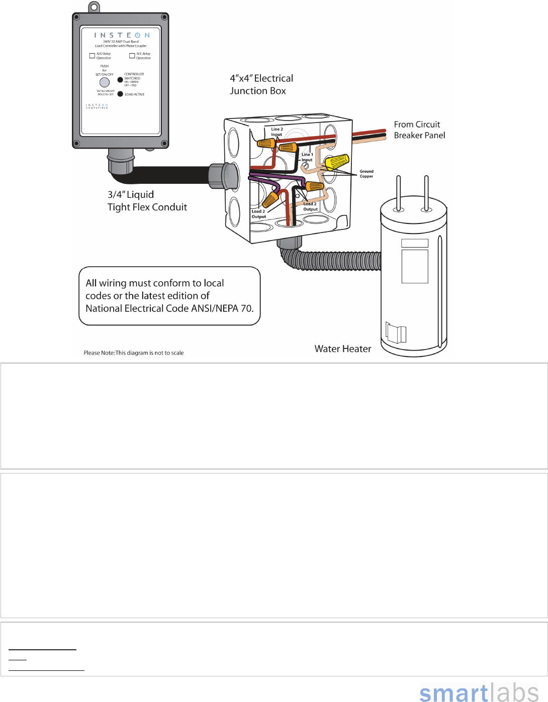
3) See Figure 1 on the next page to properly connect 240V Load
Controller to your appliance and the junction box. Connect the
240V Load Controller wires to the wires of the same color on
your appliance and junction box wherever possible.
4) Ensure that all wire connectors are firmly attached and that
there is not exposed copper except for the GROUND wire
5) Enable power to the junction box from the circuit breaker or fuse
panel
6) Test that 240V Load Controller is working properly by pressing
the Set button to toggle your appliance off, and then on
Quick-Start Guide
INSTEON® 240V 30 AMP Load Controller
(Dual-Band)
Models: 2477SA1 – Normally Open Relay
2477SA2 – Normally Closed Relay
Preparation
Because this product involves high voltage levels, it is
recommended that installation be performed only by a qualified
electrician or by a homeowner who is extremely knowledgeable and
familiar with electrical circuitry. Please take an extra level of
precaution when installing this product. If you have any questions
regarding installation, we suggest consulting an electrician.
Tools Needed
• Screwdriver (to remove cover of junction box)
• Wire cutter / stripper
• Various tools to mount 240V Load Controller to a wall
Introduction
Remotely control your appliances that run on voltages between 120
and 240 volts, up to 30 Amps. Weatherproof case allows for use
with appliances located outdoors.
Load
Active
LED
Status
LED
Using 240V Load Controller
Use the Set button on 240V Load Controller to toggle the attached load on and off
The Status LED will be solid green when the attached load is on and solid red when the load is off
The Load Active LED will be solid amber or green as long as the appliance is wired to 240V Load Controller
Page 2 of 2
Rev. 02-02-2010
SmartLabs Limited Warranty – SmartLabs warrants to original consumer of this product for a period of 2 years from date of purchase, this product will be
free from defects in material & workmanship & will perform in substantial conformity with its Owner's Manual. Warranty shall not apply to defects caused by
misuse or neglect.
U.S. Patent No. 7,345,998, International patents pending © Copyright 2010
SmartLabs, 16542 Millikan Ave., Irvine, CA 92606, 1-800-SMARTHOME
(
800-762-7846
)
Quick-Start Guide INSTEON 240V Load Controller (Dual-Band)
Complete Instructions, Troubleshooting, and Tech Support
Owner’s Manual: http://wiki.smarthome.com/index.php?title=2477SA_Manual
Call: Tech. Support @ 1-800-SMARTHOME (800-762-7846)
Contact Us Online: http://www.smarthome.com/contactus.html
Linking 240V Load Controller as a Responder to an INSTEON Controller
1) Select the INSTEON-compatible Controller you would like to use to control 240V Load Controller and set it to Linking Mode. (For
most Controllers, press & hold the On or Scene button for 10 seconds, or the Set button for 3 seconds.)
You will have 4 minutes to complete the next step.
2) Press & hold the Set button on 240V Load Controller until the unit double-beeps (about 3 seconds)
The 240V Load Controller Status LED will turn on solid green if the attached load is on or solid red if the attached load is
off
3) Test that Linking was successful by tapping the On/Off buttons on your Controller you just Linked to 240V Load Controller
240V Load Controller should respond appropriately
FCC Compliance Statement
This device complies with FCC Rules Part 15.Operation is subject to 2 conditions:
(1) This device may not cause harmful interference, and
(2) This device must accept any interference that may be received or that may cause undesired operation. The digital circuitry of this device has been tested
and found to comply with the limits for a Class B digital device, pursuant to Part 15 of the FCC Rules. These limits are designed to provide reasonable
protection against harmful interference in residential installations. This equipment generates, uses, and can radiate radio frequency energy and, if not installed
and used in accordance with the instructions, may cause harmful interference to radio and television reception. However, there is no guarantee that
interference will not occur in a particular installation. If this device does cause such interference, which can be verified by turning the device off and on, the user
is encouraged to eliminate the interference by one or more of the following measures:
• Re-orient or re-locate the receiving antenna of the device experiencing the interference
• Increase the distance between this device and the receiver
• Connect the device to an AC outlet on a circuit different from the one that supplies power to the receiver
• Consult the dealer or an experienced radio/TV technician
WARNING! Changes or modifications to this unit not expressly approved by the party responsible for compliance could void the user's authority to operate the
e
q
ui
p
ment.