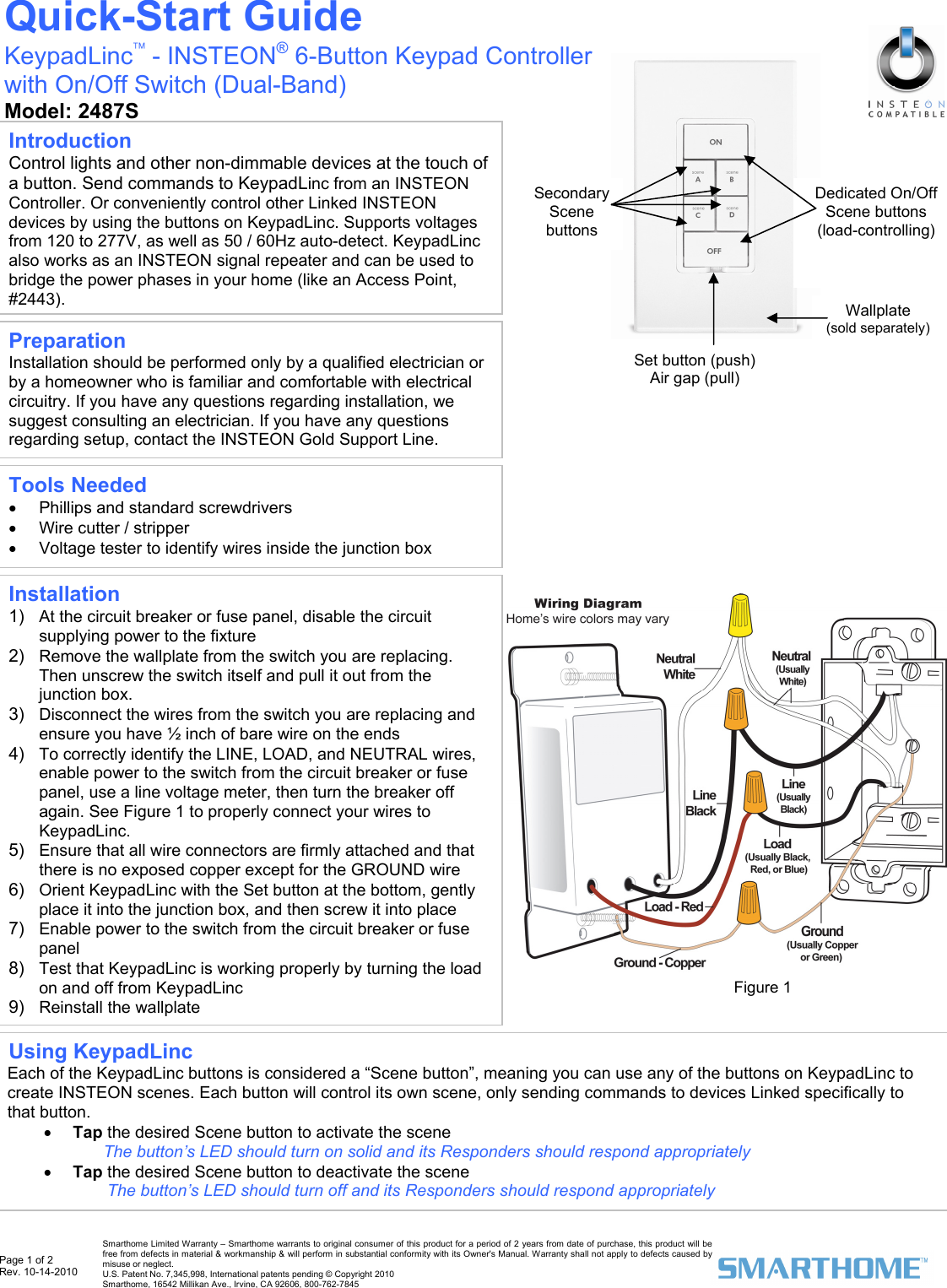
SmartLabs 2487S INSTEON 120-277V Heavy-Duty Dual-Band Wall Switch User Manual 2487S QSG 20100104

SmartLabs, Inc. INSTEON 120-277V Heavy-Duty Dual-Band Wall Switch 2487S QSG 20100104

Users Manual

 Page 1 of 2 Rev. 10-14-2010   Smarthome Limited Warranty – Smarthome warrants to original consumer of this product for a period of 2 years from date of purchase, this product will be free from defects in material & workmanship & will perform in substantial conformity with its Owner's Manual. Warranty shall not apply to defects caused by misuse or neglect.   U.S. Patent No. 7,345,998, International patents pending © Copyright 2010  Smarthome, 16542 Millikan Ave., Irvine, CA 92606, 800-762-7845                                                     Installation 1)  At the circuit breaker or fuse panel, disable the circuit supplying power to the fixture 2)  Remove the wallplate from the switch you are replacing. Then unscrew the switch itself and pull it out from the junction box.  3)  Disconnect the wires from the switch you are replacing and ensure you have ½ inch of bare wire on the ends 4)  To correctly identify the LINE, LOAD, and NEUTRAL wires, enable power to the switch from the circuit breaker or fuse panel, use a line voltage meter, then turn the breaker off again. See Figure 1 to properly connect your wires to KeypadLinc.  5)  Ensure that all wire connectors are firmly attached and that there is no exposed copper except for the GROUND wire 6)  Orient KeypadLinc with the Set button at the bottom, gently place it into the junction box, and then screw it into place  7)  Enable power to the switch from the circuit breaker or fuse panel 8)  Test that KeypadLinc is working properly by turning the load on and off from KeypadLinc  9)  Reinstall the wallplate  Quick-Start Guide KeypadLinc™ - INSTEON® 6-Button Keypad Controller with On/Off Switch (Dual-Band) Model: 2487S  Preparation Installation should be performed only by a qualified electrician or by a homeowner who is familiar and comfortable with electrical circuitry. If you have any questions regarding installation, we suggest consulting an electrician. If you have any questions regarding setup, contact the INSTEON Gold Support Line. Tools Needed •  Phillips and standard screwdrivers •  Wire cutter / stripper •  Voltage tester to identify wires inside the junction box Introduction Control lights and other non-dimmable devices at the touch of a button. Send commands to KeypadLinc from an INSTEON Controller. Or conveniently control other Linked INSTEON devices by using the buttons on KeypadLinc. Supports voltages from 120 to 277V, as well as 50 / 60Hz auto-detect. KeypadLinc also works as an INSTEON signal repeater and can be used to bridge the power phases in your home (like an Access Point, #2443).  Using KeypadLinc  Each of the KeypadLinc buttons is considered a “Scene button”, meaning you can use any of the buttons on KeypadLinc to create INSTEON scenes. Each button will control its own scene, only sending commands to devices Linked specifically to that button. • Tap the desired Scene button to activate the scene The button’s LED should turn on solid and its Responders should respond appropriately • Tap the desired Scene button to deactivate the scene  The button’s LED should turn off and its Responders should respond appropriately Figure 1 Set button (push) Air gap (pull) Dedicated On/Off Scene buttons  (load-controlling) Secondary Scene buttons Wallplate  (sold separately)
 Page 2 of 2 Rev. 10-14-2010   Smarthome Limited Warranty – Smarthome warrants to original consumer of this product for a period of 2 years from date of purchase, this product will be free from defects in material & workmanship & will perform in substantial conformity with its Owner's Manual. Warranty shall not apply to defects caused by misuse or neglect.   U.S. Patent No. 7,345,998, International patents pending © Copyright 2010  Smarthome, 16542 Millikan Ave., Irvine, CA 92606, 800-762-7845 Quick-Start Guide                                                     KeypadLinc 6-Button On/Off Switch (Dual-Band)                                                 *Setup Modes will automatically time out after 4 minutes Using KeypadLinc as a Responder 1)  Set the Controller to Linking Mode*. (For most Controllers, press & hold an On or Scene button for 10 seconds or the Set button for 3 seconds.) 2)  Press & hold the Scene button on KeypadLinc that you would like to control until it double-beeps (10 seconds). If you wish to control the load attached to KeypadLinc, press & hold the On button until it double-beeps (3 seconds) instead. The Scene button’s LED should flash once, and then turn on solid. If you used the Set button, the LED will follow the state of the load attached to KeypadLinc (On or Off) 3)  Confirm that Linking was successful by tapping the button you just Linked to on the Controller  KeypadLinc should respond appropriately  FCC Compliance Statement  This device complies with FCC Rules Part 15. Operation is subject to two conditions: (1) This device may not cause harmful interference, and (2) This device must accept any interference that may be received or that may cause undesired operation. The digital circuitry of this device has been tested and found to comply with the limits for a Class B digital device, pursuant to Part 15 of the FCC Rules. These limits are designed to provide reasonable protection against harmful interference in residential installations. This equipment generates, uses and can radiate radio frequency energy and, if not installed and used in accordance with the instructions, may cause harmful interference to radio and television reception. However, there is no guarantee that interference will not occur in a particular installation. If this device does cause such interference, which can be verified by turning the device off and on, the user is encouraged to eliminate the interference by one or more of the following measures: •  Re-orient or re-locate the receiving antenna of the device experiencing the interference. •  Increase the distance between this device and the receiver. •  Connect the device to an AC outlet on a circuit different from the one that supplies power to the receiver. •  Consult the dealer or an experienced radio/TV technician. WARNING! Changes or modifications to this unit not expressly approved by the party responsible for compliance could void the user's authority to operate the equipment. Complete Instructions, Troubleshooting, and Tech Support Owner’s Manual: http://wiki.smarthome.com/index.php?title=2487S_Manual Call: INSTEON Gold Support Line at 800-762-7845 Using KeypadLinc to Bridge Phases KeypadLinc can help bridge the phases in your home and allow RF-only devices access to power line-only devices. For the best INSTEON network performance, it is recommended that you install at least two dual-band INSTEON devices. Search for dual-band INSTEON devices at: www.smarthome.com/dualband.  Use the following procedure to test that the phases have been bridged: 1) Install additional dual-band INSTEON devices if they aren’t already installed  2)  Start Phase Bridging Detection Mode* by tapping the Set button on KeypadLinc four times quickly KeypadLinc should begin beeping and its LED should be solid The load may turn on or flash 3)  Check the LED behavior of the other dual-band devices to see if they are on the opposite phase If at least one of the other dual-band device LEDs is blinking green, or is bright solid white or blue, the device is on the opposite phase. Continue to step 4. If none of the other dual-band devices exhibit the behavior above, they are on the same phase. Try one or both of the following: •  Follow steps 2 and 3 with the other dual-band devices to see if they are bridging the phases •  Move a dual-band device to another location until it exhibits the desired LED behavior 4)  Tap the Set button on KeypadLinc to exit Phase Bridging Detection Mode KeypadLinc should stop beeping Using KeypadLinc as a Controller 1)  At the Responder, set it to the state you wish to activate from KeypadLinc 2)  Set KeypadLinc to Linking Mode* by pressing & holding the Scene button you wish to Link until it beeps (10 seconds) The Scene button’s LED should begin blinking   3)  Press & hold the Responder’s Set button for 3 seconds KeypadLinc should double-beep and the Scene button’s LED should stop blinking  4)  Confirm that Linking was successful by tapping the button you just Linked to on KeypadLinc on, and then off  The Responder should respond appropriately  Industry Canada Compliance Statement  This device complies with Industry Canada licence-exempt RSS standard(s). Operation is subject to the following two conditions: (1) this device may not cause interference, and (2) this device must accept any interference, including interference that may cause undesired operation of the device.  Le prsent appareil est conforme aux CNR d'Industrie Canada applicables aux appareils radio exempts de licence. L'exploitation est autorise aux deux conditions suivantes : (1) l'appareil ne doit pas produire de brouillage, et (2) l'utilisateur de l'appareil doit accepter tout brouillage radiolectrique subi, mme si le brouillage est susceptible d'en compromettre le fonctionnement.

Navigation menu