SmartLabs 28422 INSTEON Wireless Motion Sensor User Manual Motion Sensor
SmartLabs, Inc. INSTEON Wireless Motion Sensor Motion Sensor
UserManual.wiki
>
SmartLabs
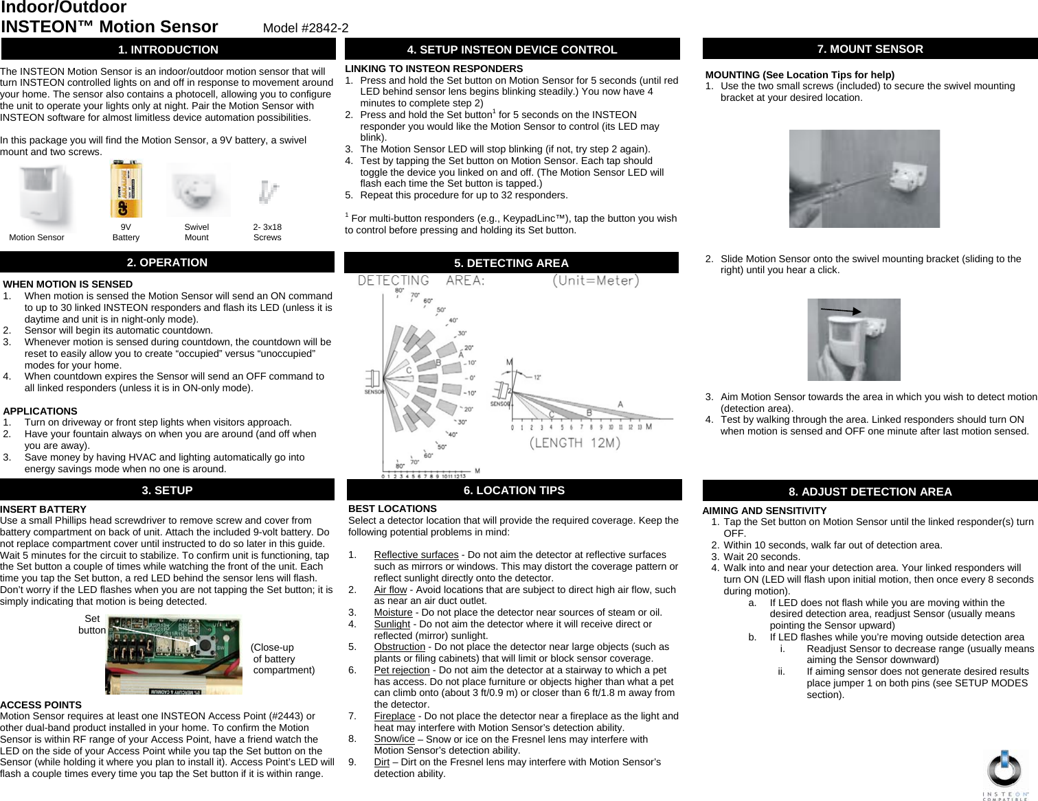
>
28422 User Manual
Users manual
Navigation menu
Upload a User Manual
Namespaces
Wiki Guide
HTML
PDF
Info
Views
User Manual
Discussion / Help
Navigation