SmartRG SR804N 802.11n DOCSIS 3.0 Gateway User Manual number
SmartRG, Inc. 802.11n DOCSIS 3.0 Gateway number
SmartRG >
User Manual
SR804n Cable Modem
User Manual
VER: 1.0

SR804n Cable Modem User Manual
i
Contents
1 Safety Introductions ......................................................................................... 1
2 Overview ......................................................................................................... 2
2.1 Application .......................................................................................... 2
2.2 Features .............................................................................................. 2
2.3 Standards Compatibility and Compliance ............................................ 3
3 Hardware Description and Hardware Installation ............................................. 4
3.1 Hardware Description .......................................................................... 4
3.1.1 Front Panel ............................................................................... 4
3.1.2 Rear Panel ............................................................................... 5
3.2 Hardware Installation ........................................................................... 5
3.2.1 Connecting the Device .............................................................. 5
4 PC Network Configuration and Login ............................................................... 7
4.1 PC Network Configuration ................................................................... 7
4.2 Logging In to the SR804N Cable Modem ............................................ 9
5 Web-Based Management .............................................................................. 10
5.1 Status ................................................................................................ 10
5.1.1 Software ................................................................................. 10
5.1.2 Connection ............................................................................. 11
5.1.3 Security .................................................................................. 12
5.1.4 Diagnostics ............................................................................. 12
5.1.5 Event Log ............................................................................... 13
5.2 Basic ................................................................................................. 14
5.2.1 Setup ...................................................................................... 14
5.2.2 DHCP ..................................................................................... 16
5.2.3 DHCPv6 ................................................................................. 17
5.2.4 LAN IPv6 ................................................................................ 18
5.2.5 DDNS ..................................................................................... 18
5.2.6 Backup ................................................................................... 19
5.3 Advanced .......................................................................................... 21
5.3.1 Options ................................................................................... 21
5.3.2 IP Filtering .............................................................................. 23
5.3.3 MAC Filtering .......................................................................... 23

SR804n Cable Modem User Manual
ii
5.3.4 Port Filtering ........................................................................... 24
5.3.5 Forwarding.............................................................................. 25
5.3.6 Port Triggers ........................................................................... 26
5.3.7 DMZ Host ............................................................................... 26
5.3.8 RIP Setup ............................................................................... 27
5.4 Firewall ............................................................................................. 30
5.4.1 Basic ...................................................................................... 30
5.4.2 Local Log ................................................................................ 31
5.4.3 Remote Log ............................................................................ 32
5.5 Parental Control ................................................................................ 33
5.5.1 User Setup ............................................................................. 33
5.5.2 Basic ...................................................................................... 34
5.5.3 ToD Filter ................................................................................ 35
5.5.4 Local Log ................................................................................ 35
5.6 VPN .................................................................................................. 36
5.6.1 Basic ...................................................................................... 36
5.6.2 IPsec ...................................................................................... 36
5.6.3 Event Log ............................................................................... 37
5.7 Wireless ............................................................................................ 38
5.7.1 Radio ...................................................................................... 38
5.7.2 Primary Network ..................................................................... 40
5.7.3 Guest Network ........................................................................ 43
5.7.4 Advanced ............................................................................... 45
5.7.5 Access Control ....................................................................... 47
5.7.6 WMM ...................................................................................... 48
5.7.7 Bridging .................................................................................. 49
5.7.8 Media ..................................................................................... 50
5.8 TR69 ................................................................................................. 50
5.8.1 TR-069 client .......................................................................... 51
5.9 USB .................................................................................................. 51
5.9.1 USB Basic .............................................................................. 52
5.9.2 Approved Devices ................................................................... 52
5.9.3 Storage Basic ......................................................................... 53
5.9.4 Storage Advanced................................................................... 53
5.9.5 Media Server .......................................................................... 54


SR804N Cable Modem User Manual
1
1 Safety Introductions
Read the following information carefully before operating the device. Please follow
the following precaution items to protect the device from risks and damage caused
by fire and electric power:
Use volume labels to mark the type of power.
Use the power adapter that is packed within the device package.
Pay attention to the power load of the outlet or prolonged lines. An
overburden power outlet or damaged lines and plugs may cause electric
shock or fire accident. Check the power cords regularly. If you find any
damage, replace it at once.
Proper space left for heat dissipation is necessary to avoid any damage
caused by overheating to the device. The holes on the device are designed
for heat dissipation to ensure that the device works normally. Do not cover
these heat dissipation holes.
Do not put this device close to a place where a heat source exits or high
temperature occurs. Avoid the device from direct sunshine.
Do not put this device close to a place where is over damp or watery. Do not
spill any fluid on this device.
Do not connect this device to any PC or electronic product, unless our
customer engineer or your broadband provider instructs you to do this,
because any wrong connection may cause any power or fire risk.
Do not place this device on an unstable surface or support.

SR804N Cable Modem User Manual
2
2 Overview
The SR804N is targeted towards DOCSIS/EuroDOCSIS3.0 cable modem, eMTA
and gateway. With eight downstream channels and four upstream channels, it
supports up to 400Mbs/160Mbs. The SR804N incorporates a variety of industry
standard peripheral interfaces including dual IEEE802.3 10/100/1000Mbps
interface, one with integrated GPHY, and dual USB2.0 interfaces(Host and
Host/Device) with integrated PHYs. The SR804N supports WLAN access. It
complies with IEEE 802.11,802.11b/g and 802.11n specifications, WEP, WPA, and
WPA2 security specifications. The WLAN of the SR804N supports 2T2R.
2.1 Application
Home gateway
SOHOs
Small enterprises
Higher data rate broadband sharing
Audio and video streaming and transfer
PC file and application sharing
Network and online gaming
2.2 Features
User-friendly GUI for web configuration
Several pre-configured popular games. Just enable the game and the port
settings are automatically configured.
Compatible with all standard Internet applications
WLAN with high-speed data transfer rates of up to 300 Mbps, compatible
with IEEE 802.11b/g/n, 2.4GHz compliant equipment
IP routing and bridging
Network/port address translation (NAT/PAT)
Wireless LAN security: WPA, 802.1x, RADIUS client
Universal plug-and-play(UPnP)
File server for network attached storage (NAS) devices
Web filtering

SR804N Cable Modem User Manual
3
Remote update
System statistics and monitoring
2.3 Standards Compatibility and Compliance
Support application level gateway (ALG)
DOCSIS/EuroDOCSIS3.0
IEEE 802.3
IEEE 802.3u
IEEE 802.11b
IEEE 802.11g
IEEE 802.11n

SR804N Cable Modem User Manual
4
3 Hardware Description and Hardware Installation
3.1 Hardware Description
3.1.1 Front Panel
The following table describes the indicators on the front panel.
Indicator
Color
Status
Description
Power
Green
On
The device is powered on and the device
operates normally.
Off
The device is powered off.
D/S
Green
On
CM has locked D/S frequency
Blink
CM scan D/S frequency
Off
Device is powered off.
U/S
Green
On
CM has locked U/S frequency
Blink
CM is range and scan U/S frequency
Off
Device is powered off or CM scan D/S
frequency.
Ethernet
1/2/3/4
Green
On
The Ethernet interface is connected.
Blink
Data is being transmitted through the
Ethernet interface.
Off
The Ethernet interface is disconnected.
WLAN
Green
On
WLAN is enabled.
Blink
Data is being transmitted through the
wireless interface.
Off
WLAN is disabled.
WPS
Green
On
Connection succeeds under Wi-Fi
Protected Setup.
Blink
Negotiation is in progress under Wi-Fi
Protected Setup.
Off
Wi-Fi Protected Setup is disabled.
USB
Green
On
The connection of USB flash disk has
established.
Off
No signal is detected.
SR804N Cable Modem User Manual
5
3.1.2 Rear Panel
The following table describes the interfaces or the buttons on the rear panel.
Interface
Description
Antenna
The antenna interface, for connecting the antennas.
Cable
RF cable port, for connecting HFC cable.
Reset
Press the button for at least 1 second and then release it. System
restores the factory default settings.
Eth 4~1
RJ-45 port, for connecting the router to a PC or another network
device.
USB 0~1
USB port, for connecting other USB storage devices.
Power
Power interface, for connecting the power adapter.
Warning:
Do not press the Reset button unless you want to clear the current settings. The
Reset button is in a small circular hole on the rear panel. If you want to restore the
default settings, please press the Reset button gently for 1 second with a fine needle
inserted into the hole and then release the button. The system reboots and returns to
the factory defaults.
Ne pas appuyer sur le bouton de réinitialisation, sauf si vous voulez effacer les
réglages actuels. Le bouton de réinitialisation est dans un petit trou circulaire sur le
panneau arrière. Si vous souhaitez restaurer les paramètres par défaut, se il vous
plaît appuyez sur le bouton de réinitialisation doucement pendant 1 seconde avec
une fine aiguille insérée dans le trou, puis relâchez le bouton. Le système redémarre
et revient aux valeurs par défaut.
3.2 Hardware Installation
3.2.1 Connecting the Device
Please follow the steps below to connect the device.
Step1 Connect the Cable port of the CMRG with HFC cable.

SR804N Cable Modem User Manual
6
Step2 Connect the Eth port of the CMRG to the network card of the PC via an
Ethernet cable.
Step3 Plug one end of the power adapter to the wall outlet and connect the
other end to the Power port of the CMRG.

SR804N Cable Modem User Manual
7
4 PC Network Configuration and Login
4.1 PC Network Configuration
Each network interface on the PC should either be configured with a statically defined
IP address and DNS address, or be instructed to automatically obtain an IP address
using the network DHCP server. SR804N provides a DHCP server on its LAN and it
is recommended to configure your LAN to automatically obtain its IP address and
DNS server IP address.
The configuration principle is identical but should be carried out differently on each
operating system.
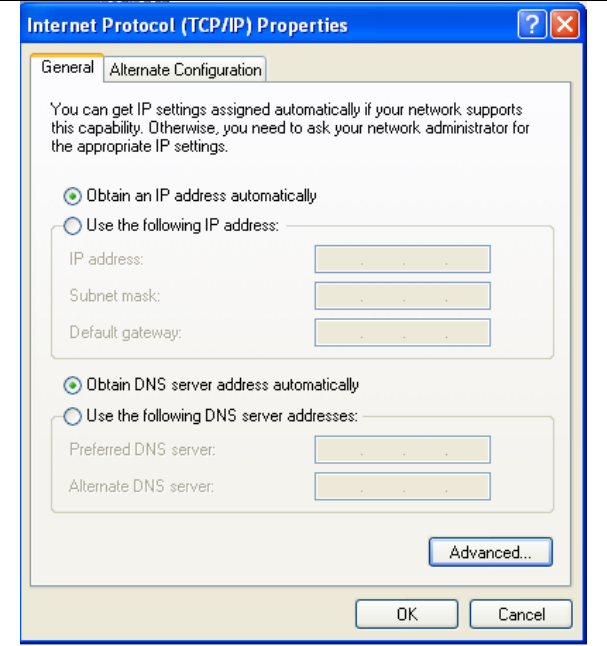
The following displays the TCP/IP Properties dialog box on Windows XP.
SR804N Cable Modem User Manual
8
Figure 1 IP and DNS configuration
TCP/IP configuration steps for Windows XP are as follows:
Step1 Choose Start > Control Panel > Network Connections.
Step2 Right-click the Ethernet connection icon and choose Properties.
Step3 On the General tab, select the Internet Protocol (TCP/IP) component
and click Properties.
Step4 The Internet Protocol (TCP/IP) Properties window appears.
Step5 Select the Obtain an IP address automatically radio button.

SR804N Cable Modem User Manual
9
Step6 Select the Obtain DNS server address automatically radio button.
Step7 Click OK to save the settings.
4.2 Logging In to the SR804N Cable Modem
To log in to the SR804Ncable modem, do as follows:
Step1 Open a Web browser on your computer.
Step2 Enter http://192.168.100.1 (the default IP address of the SR804Ncable
modem) in the address bar. The login page appears.
Step3 Enter the user name and the password. The default Username is admin
and the Password is admin.
Step4 Click OK to log in to the Web page. Otherwise, please click Cancel to exit
the login page.
Figure 2 Login page
After logging in to the SR804N cable modem, you can query, configure, and modify
all the settings, and diagnose the system.
SR804N Cable Modem User Manual
10
5 Web-Based Management
This chapter describes how to use Web-based management of the Cable Modem,
which allows you to configure and control all of cable modem residential gateway
features and system parameters in a user-friendly GUI.
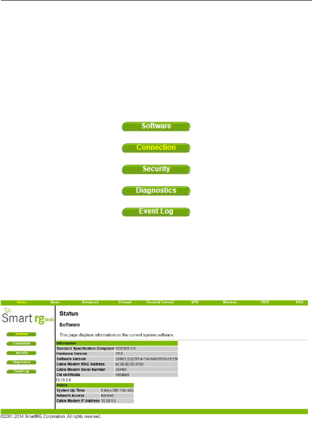
5.1 Status
Choose Status, and the submenus of Status are shown as below.
Figure 3 Submenus of Status
5.1.1 Software
Choose Status > Software , and the following page appears.
SR804N Cable Modem User Manual
11
Figure 4 Software page
This page displays information about the hardware version, software version, MAC
address, cable modem IP address, serial number, system “up” time, and network
registration status.
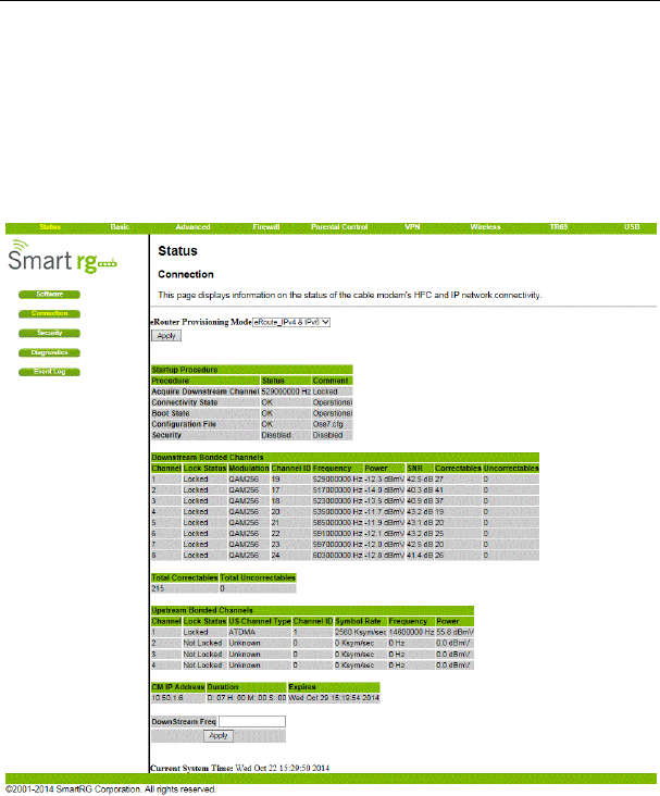
5.1.2 Connection
Choose Status > Connection and the following page appears.
Figure 5 Connection information
This page displays information about the RF upstream and downstream channels,
including downstream channel frequencies, upstream channel IDs, and upstream and
downstream signal power and modulation.

SR804N Cable Modem User Manual
12
This page also displays IP lease information, including the current IP address of the
cable modem, the duration of both leases, the expiration time of both leases, and the
current system time from the DOCSIS timeserver.
The information on this page can be refreshed at any time by clicking your web
browser‟s Refresh button.
5.1.3 Security
Choose Status > Connection and the following page appears.
Figure 6 Security configuration
To restore factory defaults, select the Yes radio button and click Apply. This will
cause the device to reset. The factory default password is “Broadcom” and is
case sensitive.
Note that you can also change the security password from this page by entering a
new password in both the New Password and Re-Enter New Password fields, and
the current password in the Current User ID Password field. Clicking Apply will
change the password. You do NOT have to restore factory defaults to change the
password.
5.1.4 Diagnostics
Choose Status > Diagnostics and the following page appears.
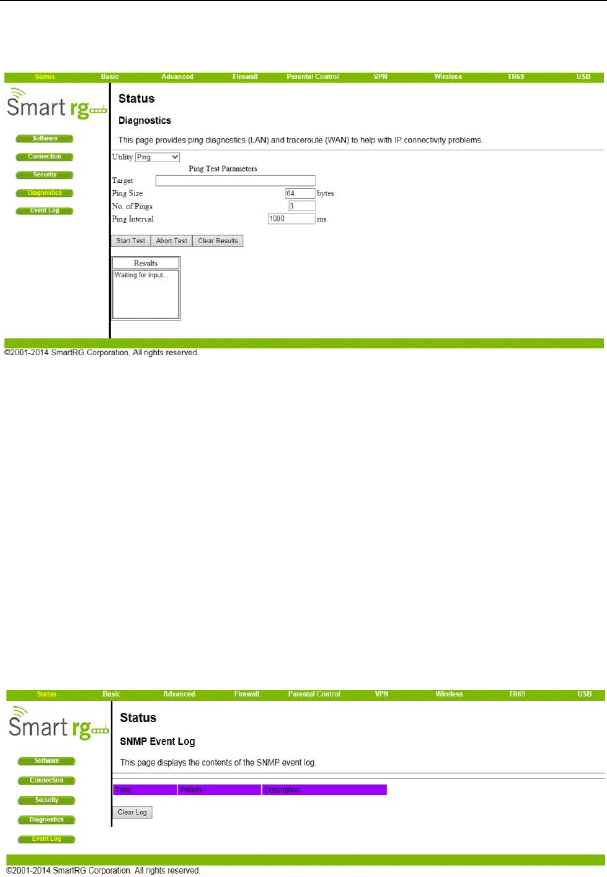
SR804N Cable Modem User Manual
13
Figure 7 Diagnostic information
Two utilities are provided for troubleshooting network connectivity: Ping and
Traceroute.
Ping allows you to check connectivity between the CMRG and devices on the LAN.
Traceroute allows you to map the network path from the CMRG to a public host.
Selecting Traceroute from the drop-down Utility list will present alternate controls for
the traceroute utility: To run either utility, make any changes to the default parameters
and select Start Test to begin. The window will automatically be refreshed as the
results are displayed in the Results table.
5.1.5 Event Log
Choose Status > Event Log to display the following page.
SR804N Cable Modem User Manual
14
Figure 8 Event Log information
This page displays the contents of the SNMP event log.
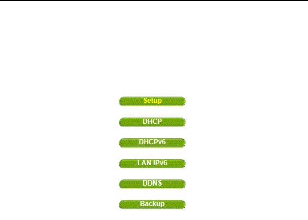
5.2 Basic
Choose Basic and the submenus of Basic are shown as below.
Figure 9 Submenus of basic
5.2.1 Setup
Choose Basic > Setup , and the following page appears.
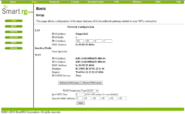
SR804N Cable Modem User Manual
15
Figure 10 Setup configuration
Enter the information from the Required Information section as indicated:
1.If your ISP uses DHCP, select “DHCP” for the WAN Connection Type, and enter
Host Name and Domain name if required. OR
If your ISP uses static IP addressing, select “Static IP” for the WAN Connection
Type, and enter the information provided by your ISP for Static IP Address, Static IP
Mask, Default Gateway, Primary DNS, and Secondary DNS.
2.Enter a unicast MAC address in the Spoofed MAC Address field. Your ISP may
require this to be your PC‟s MAC address. If not, you can simply supply the WAN
side MAC address of the router as your CPE and leave the spoofed MAC address
entry set to all 0‟s, since there will be no spoofing required.
3.Select the Apply button. This will reset the CMRG.
At this point, the CMRG is configured for basic use. To connect to the Internet,
you must do the following:
1.Power up the CMRG and wait for it to register with the CMTS and obtain an
Internet-routable IP address
2.Get an IP lease from the internal DHCP server for each PC attached to the
CMRG.
SR804N Cable Modem User Manual
16
Note that communication on the LAN will work regardless of whether the WAN
connection provided by the cable modem is up. However, you will not be able to
access the Internet until the WAN connection is enabled and has an IP address.
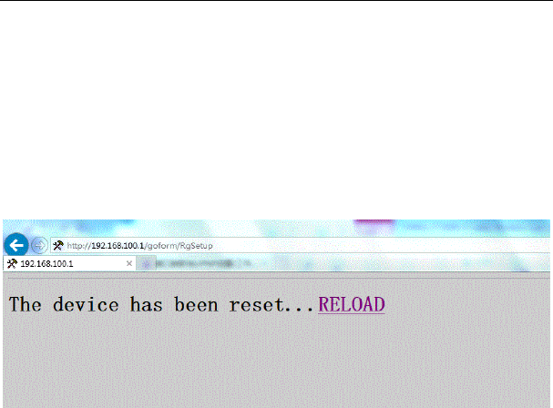
Some configurations settings are retrieved only once from non-volatile storage
when the CMRG first powers up. One such setting is changing the Static WAN IP
address parameters. Any changes to these settings will force the CMRG to reset
so that the new configuration can be read from non-volatile storage.
When this mandatory reset is required, the web interface will notify as follows:
Figure 11 Reload page
Simply wait for the modem to reboot and click on the “RELOAD” link to re-enter the
web interface where you made your last change.
Most configuration items may be changed on the fly without a reboot.
5.2.2 DHCP
Choose Basic > DHCP, and the following page appears.
SR804N Cable Modem User Manual
17
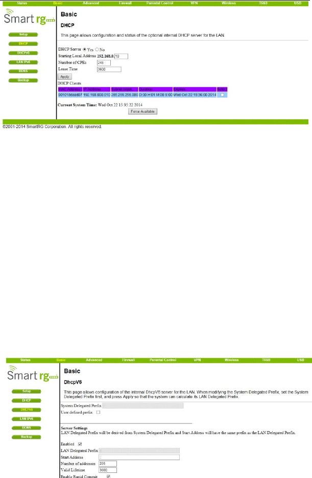
Figure 12 DHCP configuration
This page allows configuration and status of the optional internal DHCP server for the
LAN.
If you have your own DHCP server servicing the LAN side (or choose to “hardcode”
all of your PC‟s IP addresses), you can disable the internal DHCP server by selecting
the No radio button. If you do this, make sure the IP address assigned to the CMRG
is on the same subnet as the external DHCP server (the subnet mask is always
255.255.255.0), or you won‟t be able to access the CMRG from the LAN. The IP
address of the CMRG can be set from the Basic Setup page.
You can also set the starting IP address for IP leases available to the LAN, and
change the number of PCs supported on the LAN. In the case above, addresses
192.168.0.2 through 192.168.0.9 can be used as hard-coded IP addresses with no
fear of IP address conflict with the DHCP pool. Configured WINS server addresses
can also be passed to CPEs behind the CMRG via DHCP.
5.2.3 DHCPv6
Choose Basic > DHCPv6 , and the following page appears.
SR804N Cable Modem User Manual
18
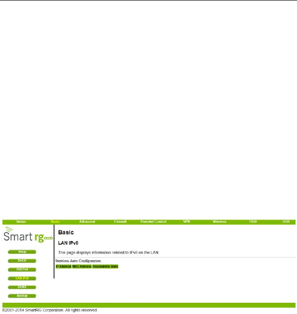
Figure 13 DHCPv6 configuration
This page allows configuration of the internal DhcpV6 server for the LAN. When
modifying the System Delegated Prefix, set the System Delegated Prefix first, and
press Apply so that the system can calculate its LAN Delegated Prefix.
5.2.4 LAN IPv6
Choose Basic > LAN IPv6 , and the following page appears.
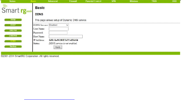
Figure 14 LAN IPv6 information
This page displays information related to IPv6 on the LAN.
5.2.5 DDNS
Choose Basic > DDNS , and the following page appears.
SR804N Cable Modem User Manual
19
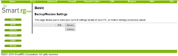
Figure 15 DDNS setup
This page is used to configure DDNS. Dynamic DNS (DDNS) allows a dynamic IP
address to be aliased to a static, pre-defined host name so that the host can be
easily contacted by other hosts on the internet even if its IP address changes.
The CMRG supports a dynamic DNS client compatible with the Dynamic DNS
service (http://www.dyndns.com/).
To activate the DDNS client:
1. Go to the DynDNS website and create an account for the Dynamic DNS service.
You will create a username and password, and be asked to choose a host name for
your server, and the dynamic DNS domain to which your host will be assigned.
You will also be asked for your host‟s current IP address. This is the WAN IP
address that has been assigned to your CMRG during provisioning. (See WAN IP
Address on the Basic / Setup web page.)
2. Enter your account information on the Basic / DDNS web page, enable the
service by selecting www.DynDNS.org from the DDNS Service drop-down list, and
click Apply.
3. The DDNS client will notify the DDNS service whenever the WAN IP address
changes so that your chosen host name will be resolved properly by inquiring hosts.
The current status of the service is shown at the bottom of the DDNS web page.
5.2.6 Backup
Choose Basic > Backup and the following page appears.
SR804N Cable Modem User Manual
20
Figure 16 Backup
In this page, you can save the current CMRG configuration settings to a local PC.
You can then later restore these settings if you need restore a particular
configuration, or to recover from changes you may have made that have had an
undesirable effect.
To backup the current configuration, click Backup and follow the prompts.
To restore a previous configuration, click Browse and use the navigation window to
locate the file. (Usually GatewaySettings.bin, unless you rename it before
saving.) Once the file has been located, click Restore to restore the settings.
Note that once the settings are restored, the device will reboot.
SR804N Cable Modem User Manual
21
5.3 Advanced
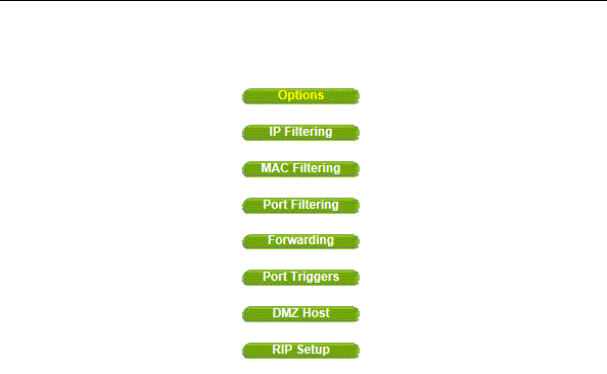
Choose Advanced and the submenus of Advanced are shown as below.
Figure 17 Submenus of advanced
5.3.1 Options
Choose Advanced > Options to display the following page.
SR804N Cable Modem User Manual
22
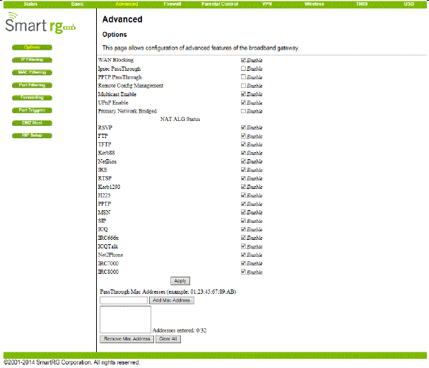
Figure 18 Advanced options
This page allows you to configure the accessible features.
To enable a feature, click the appropriate check box until it is “checked”. When you
are satisfied with your selections, click on the Apply button. These features can be
modified on the fly without a system reset.
“WAN Blocking” prevents the CMRG or the PCs behind it from being visible to the
WAN. For instance, pings to the CMRG‟s WAN IP address or the PCs behind it are
not returned. Therefore, it will be more difficult for hacker to discover your WAN IP
address to begin an attack on your private LAN.
“IpSec” and “PPTP” (Point-to-Point Tunneling Protocol) pass-through modes enable
these protocols to be used through the CMRG such that a VPN device (or software)
may communicate properly with the WAN.
“Remote Configuration Management” allows the CMRG to be administered
(configured) from the WAN via surfing to the WAN IP address on port 8080 of the
CMRG from anywhere on the Internet (e.g. at the browser URL window enter
http://WanIPAddress:8080/ to access the CMRG remotely).
SR804N Cable Modem User Manual
23
“Multicast Enable” allows multicast specific traffic (denoted by a multicast specific
address) to be passed to and from the PC‟s on the private network behind the CMRG.
“UPnP Enable” enables the UPnP agent in the CMRG. If you are running a CPE
application that requires UPnP, check this box.
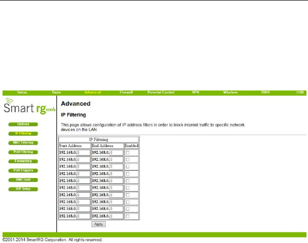
5.3.2 IP Filtering
Choose Advanced > IP Filtering to display the following page.
Figure 19 IP Filtering configuration
This page allows you to configure the CMRG to prevent local PCs from getting
access to the WAN by specifying those IP addresses that should be filtered.
By entering starting and ending IP address ranges, you can configure which local
PCs are denied access to the WAN. Note that you only need to enter the LSB
(Least-significant byte) of the IP address; the upper bytes of the IP address are set
automatically from the CMRG IP address. To activate the IP address filter, you must
also check the “enable” box and click apply. The enable box allows you to store filter
settings commonly used but not have them active.
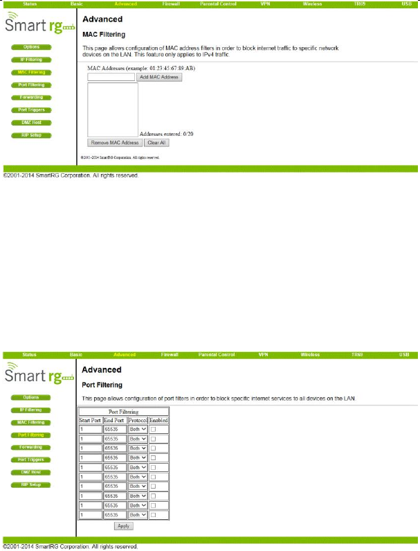
5.3.3 MAC Filtering
Choose Advanced > MAC Filtering to display the following page.
SR804N Cable Modem User Manual
24
Figure 20 MAC filtering configuration
This page is used to prevent PCs from sending outgoing TCP/UDP traffic to the WAN
via their MAC address
This is useful for the fact that the MAC address of a specific NIC card never changes,
unlike its IP address which can be assigned via DHCP server or hard-coded to
various addresses over time.
5.3.4 Port Filtering
Choose Advanced > Port Filtering to display the following page.
SR804N Cable Modem User Manual
25
Figure 21 Port Filtering configuration
This page is used to prevent PCs from sending outgoing TCP/UDP traffic to the WAN
on specific IP port numbers.
By specifying a starting and ending port range, you may determine what TCP/UDP
traffic is allowed out to the WAN on a per-port basis. Note the specified port ranges
are blocked for ALL PCs and this setting is not IP address or MAC address specific.
For instance, if you would like to block all PCs on the private LAN from accessing
HTTP sites (or “web surfing”), you would set the “Start Port” to 80, the “End Port” to
80, the “Protocol” to TCP, check the “Enabled” box, and click Apply.
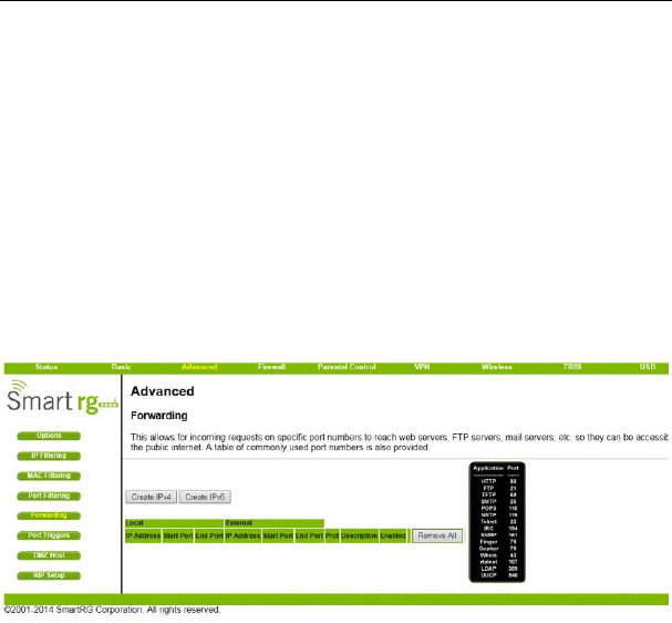
5.3.5 Forwarding
Choose Advanced > Forwarding to display the following page.
Figure 22 Forwarding
This allows for incoming requests on specific port numbers to reach web servers, FTP
servers, mail servers, etc. so they can be accessible from the public internet. A table
of commonly used port numbers is also provided.
Forwarding allows you to run a publicly accessible server on the LAN by specifying
the mapping of TCP/UDP ports to a local PC
To specify a mapping, you must enter the range of port numbers that should be
forwarded locally, and the IP address to which traffic to those ports should be sent. If
only a single port specification is desired, enter the same port number in the “start”
and “end” locations for that IP address. A table of commonly used Port numbers is
supplied on the page for convenience.
SR804N Cable Modem User Manual
26
If both external and Local/internal port numbers are present, the Local port number is
a mandatory field and the external port number is optional. If the external port
number is used, the RG will perform a translation from external port number to
internal port number.
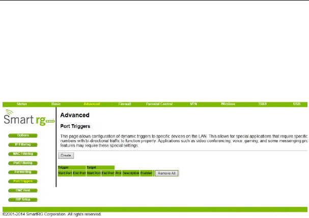
5.3.6 Port Triggers
Choose Advanced > Port Triggers to display the following page.
Figure 23 Port Triggers
Port Triggers are similar to Port Forwarding except that they are not static ports held
open all the time. When the CMRG detects outgoing data on a specific IP port
number set in the “Trigger Range”, the resulting ports set in the “Target Range” are
opened for incoming (or sometimes referred to as bi-directional ports) data. If no
outgoing traffic is detected on the “Trigger Range” ports for 10 minutes, the “Target
Range” ports will close. This is a safer method for opening specific ports for special
applications (e.g. video conferencing programs, interactive gaming, file transfer in
chat programs, etc.) because they are dynamically triggered and not held open
constantly or erroneously left open via the router administrator and exposed for
potential hackers to discover.
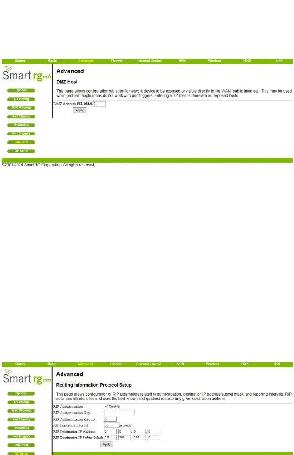
5.3.7 DMZ Host
Choose Advanced > DMZ Host to display the following page.
SR804N Cable Modem User Manual
27
Figure 24 DMZ Host setup
DMZ (De-militarized Zone) hosting (also commonly referred to as “Exposed Host”)
allows you to specify the “default” recipient of WAN traffic that NAT is unable to
translate to a known local PC. This can also be described as a computer or small
sub-network that sits between the trusted internal private LAN, and the untrusted
public Internet.
You may configure one PC to be the DMZ host. This setting is generally used for
PC‟s using “problem” applications that use random port numbers and do not function
correctly with specific port triggers or port forwarding setups mentioned earlier. If a
specific PC is set as a DMZ Host, remember to set this back to “0” when finished with
the needed application, since this PC will be effectively exposed to the public Internet,
though still protected from Denial of Service (DoS) attacks via the Firewall.
5.3.8 RIP Setup
Choose Advanced > RIP Setup to display the following page.

SR804N Cable Modem User Manual
28
Figure 25 RIP Setup
RIP (Router Information Protocol) is used in WAN networks to identify and use the
best known and quickest route to given destination addresses to help reduce network
congestion and delays.
NOTE: RIP messaging will only be sent upstream when running in Static IP
Addressing mode on the Basic – Setup page. You must enable Static IP Addressing
and the set the Wan IP network information! RIP is normally a function that is tightly
controlled via the ISP. RIP Authentication Keys and IDs are normally held as secret
information from the end user to prevent unauthorized RIP settings.
RIP is a protocol that requires negotiation from both sides of the network (i.e. CMRG
and CMTS). The ISP would normally set this up because of their knowledge of their
CMTS settings to match the configuration in the CMRG.
To enable the CMRG to perform RIP, do the following (this example uses BRCMV2 as
the RIP Authentication Key and 1 as the Key ID):
1.) To turn on RIP MD5 Authentication, check the “Enable” box.
2.) To specify a RIP MD5 Authentication Key String, type “BRCMV2” for this example.
key name = a string value to match CMTS key name value
3.) To specify a RIP MD5 Auth Key ID, type “1”
key number = a number to match the CMTS key number value
4.) To change the RIP annoucement interval, type in a number in seconds.reporting
interval by default = 30 seconds
5.) To specify a RIP unicast destination IP address, enter the IP address and subnet
mask.
To enable the CMTS for RIPv2 with MD-5 authentication (Cisco uBR example shown
below):
1.) The following steps go through configuring RIPv2 for a Cisco CMTS. The network
number used in this configuration will vary from network to network so use the
network number that matches your set-up.
7223#configure terminal
7223(config)#key chain ubr
7223(config-keychain)#key 1

SR804N Cable Modem User Manual
29
7223(config-keychain-key)#key-str BRCMV2
7223(config-keychain-key)#exit
7223(config-keychain)#exit
7223(config)#router rip
7223(config-router)#ver 2
7223(config-router)#no validate-update
7223(config-router)#passive-interface cable 2/0
7223(config-router)#network 10.0.0.0
7223(config-router)#exit
7223(config)#inter cable 2/0
7223(config-if)#ip rip receive ver 2
7223(config-if)#ip rip authentication mode md5
7223(config-if)#ip rip authentication key-chain ubr
7223(config-if)#exit
7223(config)#exit
In this example, we have named the key chain „ubr‟. This was chosen arbitrarily. You
can use any name you like as long as you specify the correct name when specifying
which key chain to use for RIPv2 authentication.
2.) The next step is enable RIP debugging to ensure that the CMTS is receiving and
authenticating messages from the residential gateway.
7223#debug ip rip
RIP protocol debugging is on
7223#term mon
The CMTS is now configured to accept RIPv2 messages. If the CMRG is registered
on the CMTS, you should see messages that are similar to the message below:
00:28:41: RIP: received packet with MD5 authentication
00:28:41: RIP: received v2 update from 10.24.81.148 on Cable2/0
00:28:41: 10.24.81.0/24 via 10.24.81.148 in 1 hops
The CMRG has broadcast that is connected to the network 10.24.81.0/24 through
the interface 10.24.81.148. This information is not very useful to the CMTS because it
already knows that the network 10.24.81.0/24 is connected directly to one of its
interfaces (Cable2/0). It ignores this message and doesn‟t add any information to the
IP routing table. Here is the IP routing table after the CMTS has received RIPv2
messages:
7223#sh ip route
SR804N Cable Modem User Manual
30
Codes: C - connected, S - static, I - IGRP, R - RIP, M - mobile, B - BGP
D - EIGRP, EX - EIGRP external, O - OSPF, IA - OSPF inter area
N1 - OSPF NSSA external type 1, N2 - OSPF NSSA external type 2
E1 - OSPF external type 1, E2 - OSPF external type 2, E - EGP
i - IS-IS, L1 - IS-IS level-1, L2 - IS-IS level-2, ia - IS-IS inter area
* - candidate default, U - per-user static route, o - ODR
P - periodic downloaded static route
Gateway of last resort is 10.24.95.17 to network 0.0.0.0
10.0.0.0/8 is variably subnetted, 3 subnets, 2 masks
C 10.24.80.0/24 is directly connected, Cable2/0
C 10.24.81.0/24 is directly connected, Cable2/0
C 10.24.95.16/28 is directly connected, FastEthernet0/0
S* 0.0.0.0/0 [1/0] via 10.24.95.17
In the example above, the CMRG was set up to send RIPv2 messages to the CMTS.
The CMTS was also set up to receive these messages.
5.4 Firewall
Choose Firewall and the submenus of Firewall are shown as below.
Figure 26 submenus of Firewall
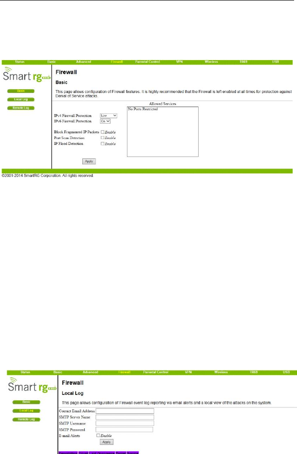
5.4.1 Basic
Choose Firewall > Basic to display the following page.
This page is used to block or exclusively allow different types of data through the
CMRG from the WAN to the LAN.
SR804N Cable Modem User Manual
31
Figure 27 Basic configuration
The “low” setting does not block any services/ports, however it does protect against
invalid packets and well known attacks. The “medium” setting will cause the firewall to
drop a packet unless it is on a specific port of allowed services, The allowed services
are listed on the same page. The “high” setting is similar to “medium”, but allows
access to even fewer services. The “off” setting allows all traffic to pass.
Block Fragmented IP packets prevents all fragmented IP packets from passing
through the firewall. Port Scan Detection detects and blocks port scan activity
originating on both the LAN and WAN. IP Flood Detection detects and blocks packet
floods originating on both the LAN and WAN. The Apply button must be clicked in
order to activate any of the checkbox items. All of these settings can be activated
on-the-fly without a CMRG reboot.
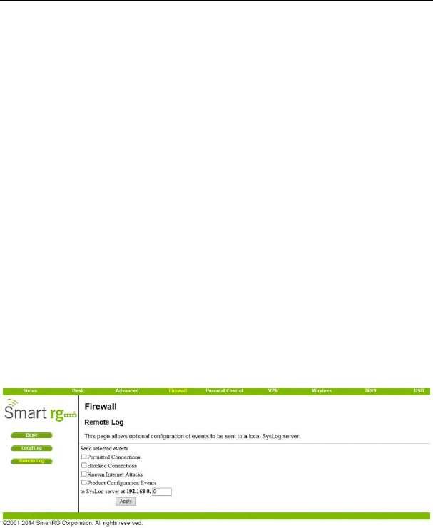
5.4.2 Local Log
Choose Firewall > Local Log to display the following page.
SR804N Cable Modem User Manual
32
Figure 28 Local Log
The Local Log can send firewall attack reports out in two different ways. Individual
emails can be sent out automatically, each time the firewall is under attack, and also a
local log is stored within the modem and displayed in table form on the Local Log
page.
To enable the automatic email alerts, enter your email address in the space provided,
enter that email account‟s associated SMTP (Outgoing) mail server address and
authentication credentials if required (provided by your ISP), check the “enable” box
and click the Apply button. Individual emails will now be sent to the specified
address each time an attack is detected. Each attack is also logged in the table on
the Event Log page. If desired, a summary of the Event Log Table can be sent to the
specified contact email address by clicking on the Email Log button. Clicking on the
Clear Log button can also clear the table.
5.4.3 Remote Log
Choose Firewall > Remote Log to display the following page.
Figure 29 Remote Log
The Remote Log can send firewall attack reports out to a standard SysLog server so
many instances can be logged over a long period of time. Individual attack or
configuration items can be selected that will be sent to the SysLog server such that
only the items of interest can be monitored. Permitted connections, blocked
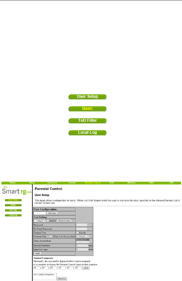
SR804N Cable Modem User Manual
33
connections, known Internet attack types, and CMRG configuration events can be
logged. The SysLog server must be on the same network as the Private LAN
behind the CMRG (typically 192.168.0.x). To activate the SysLog monitoring feature,
check all desired event types to monitor and enter the last byte of the IP address of
the SysLog server. Normally, the IP address of this SysLog server would be
hard-coded so that the address will not change and always agrees with the entry on
this page.
5.5 Parental Control
Choose Parental Control and the submenus of Parental Control are shown as
below.
Figure 30 Submenus of Parental Control
5.5.1 User Setup
Choose Parental Control > User Setup to display the following page.
SR804N Cable Modem User Manual
34
Figure 31 User Setup
Add users who will be affected by Parental Control, and assign Policies to these
users. (See Basic page). The White List Only feature limits the user to those sites
specified in the Allowed Domain List of the Policy you have assigned to him or her.
Click the Add User and Remove User buttons as appropriate to save changes.
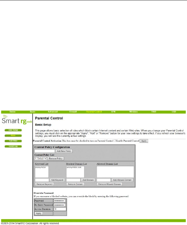
5.5.2 Basic
Choose Parental Control > Basic to display the following page.
Figure 32 Basic setup
Make rules to block access to certain web sites, and allow access to others. Do this
by defining one or more Policies. Click the Apply, Add New Policy and Remove Policy
buttons as appropriate to save changes. Click your browser's Refresh button to see
the currently active settings.
SR804N Cable Modem User Manual
35
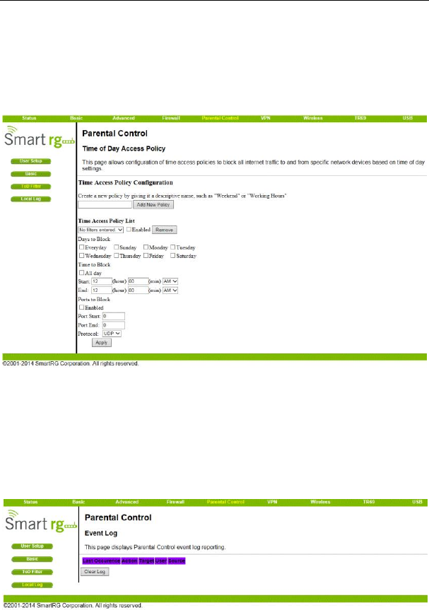
5.5.3 ToD Filter
Choose Parental Control > ToD Filter and the following page will be shown.
Figure 33 ToD Filter configuration
Create a policy or policies to block all Internet access on certain days and/or times of
day.
5.5.4 Local Log
Choose Parental Control > Local Log and the page will be shown as below.
SR804N Cable Modem User Manual
36
Figure 34 Local Log information
This page displays the Parental Control event log.
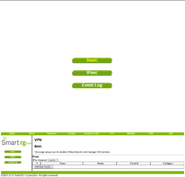
5.6 VPN
Choose VPN and the submenus of VPN are shown as below.
Figure 35 Submenus of VPN
5.6.1 Basic
Choose VPN > Basic to display the following page.
Figure 36 Basic settings
This page will show the status of configured tunnels .To start the process of manually
adding a new tunnel , select the “Add New Tunnel” button.
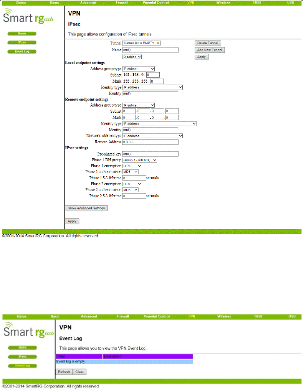
5.6.2 IPsec
Choose VPN > IPsec to display the following page.
SR804N Cable Modem User Manual
37
Figure 37 IPsec
In this page, you are allowed to configure all aspects of the IPSec tunnel.
5.6.3 Event Log
Choose VPN > Event Log to display the following page.
Figure 38 Event Log information
This page allows you to view the VPN Event Log.
SR804N Cable Modem User Manual
38
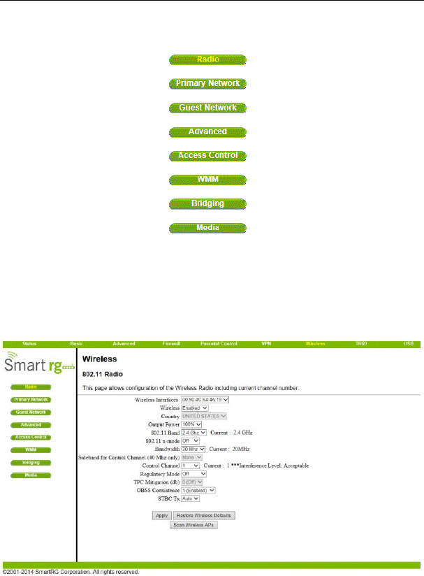
5.7 Wireless
Choose Wireless and the submenus of Wireless are shown as below.
Figure 39 Submenus of Wireless
5.7.1 Radio
Choose Wireless > Radio to display the following page.
Figure 40 Radio setting

SR804N Cable Modem User Manual
39
This page allows configuration of the physical parameters of your wireless network.
The MAC address of the wireless interface is displayed at the top of the page.
Wireless:
Allows the wireless interface to be enabled and disabled.
Country:
Restricts the channel set based on the selected country‟s regulatory requirements.
Output Power:
Control the range of the AP by adjusting the radio output power.
802.11 Band:
Select the radio operates in the 2.4 GHz band.
802.11 n-mode:
Switch this to Off to force the AP to operate in 802.11g mode.
802.11 N Support Required:
If the 802.11 N support required field is set to “on”, then only .n capable stations are
allowed to associate with the CM. If it‟s set to “off” then b/g/n are all allowed.
Bandwidth:
802.11b/g channels are only 20 MHz wide, but 802.11n channels may be 40 MHz
wide. There are some backward compatibility issues with 40 MHz channels though.
These issues are more likely to be encountered in the 2.4 GHz band where legacy
(802.11b/g) devices may be operating using 20 MHz channels.
Sideband for Control Channel (40 MHz only):
Whether the 20 MHz control channel uses the upper or lower half of the 40 MHz
channel. Changes to this setting may change the control channel setting. For
example (in the 2.4 GHz band), if the upper 20 MHz is selected as the sideband for
the control channel, then the lowest control channel available would be channel 5
to allow the lower 20 MHz for data.
Control Channel:
Selects the control channel for AP operation. The list of available channels
depends on the selected country as presented in
Table 1. Next to the drop-down list box, the current channel number is displayed.
Table 1. Allowed Channels by Country:

SR804N Cable Modem User Manual
40
Regulatory Mode:
Selects either 802.11d or 802.11h modes of operation. These are amendments to the
802.11 specifications for solving interference issues with other transmission systems
such as satellite or radar, and also transmission requirements in different parts of the
world.
TPC Mitigation (dB):
Transmit Power Control mitigation factor in dB. Transmit Power Control is used to
automatically reduce the transmission power when other networks are within range.
This setting is only used when the Regulatory Mode is set to 802.11h.
OBSS Coexistence:
Enable/Disable Overlapping BSS Coexisistence. OBSS coexistence refers to the
ability of the AP to support 20 MHz devices within 40 MHz channels. It also allows the
AP to better deal with nearby 20 MHz devices that are interfering with part of its 40
MHz channel.
STBC Tx:
STBC :Space Time Block Code. Switch to on will obtain the full antenna gain.
Scan Wireless AP’s:
Force the Modems Access Point to scan for other AP‟s within receive range.
Apply:
When any of the above settings are changed, the Apply button must be clicked in
order to activate them.
5.7.2 Primary Network
Choose Wireless > Primary Network to display the following page.
Country
First Channel
Last Channel
USA
1
11
Worldwide, China, Europe
1
13
Japan, Thailand, All Channels
1
14
Israel
5
7
Jordan
10
13
SR804N Cable Modem User Manual
41
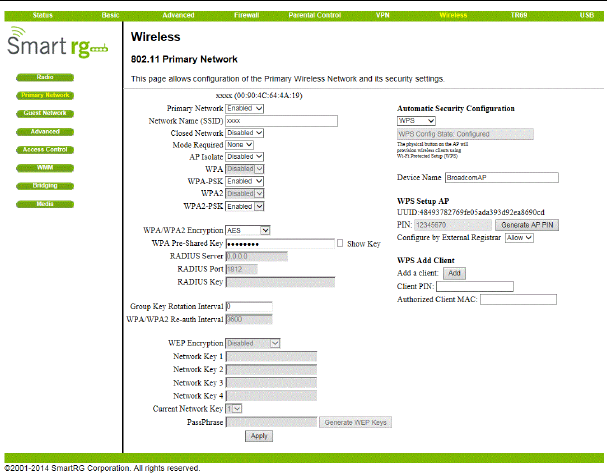
Figure 41 Primary Network configuration
This page allow you to configure the Primary Wireless Network.
Primary Network:
Enable or Disable the primary network. Guest networks may still be operational when
the primary network is disabled.
Network Name (SSID):
Sets the Network Name (also known as SSID) of the primary network. This is a 1-32
ASCII character string.
Closed Network:
The Network Name is not broadcast by the AP in a Closed Network. Therefore, only
clients who already know the network name will be able to connect.
WPA:
Wi-Fi Protected Access is a slightly older and less secure algorithm for securing a
wireless network. This is the Enterprise variant that requires configuration of a
RADIUS server.

SR804N Cable Modem User Manual
42
WPA-PSK:
The Pre-Shared Key mode of the WPA algorithm which does not require use of a
RADIUS server. This is also known as WPA Personal. WPA and WPA-PSK cannot be
used at the same time.
WPA2:
An advanced form of WPA that is more secure. This is the Enterprise mode of WPA2
which requires the use of a RADIUS server. WPA2 and WPA may be used at the
same time to provide backward compatibility with devices that do not support WPA2.
WPA2-PSK:
The Pre-Shared Key mode of WPA2, also known as WPA2 Personal. WPA2 and
WPA2-PSK cannot be used at the same time. WPA2-PSK and WPA-PSK may be
used at the same time to provide backward compatibility with devices that do not
support WPA2.
WPA/WPA2 Encryption:
When using any of the WPA authentication schemes, AES, or TKIP + AES encryption
modes can be set. AES provides the strongest encryption, while TKIP provides strong
encryption with improved backward compatibility. The TKIP + AES mode allows both
TKIP and AES-capable clients to connect.
WPA Pre-Shared Key:
Sets the WPA Pre-Shared Key (PSK). This is an 8-63 ASCII character string, or a
64-digit hex number. Enabled when the Network Authentication method is
WPA-PSK or WPA2-PSK.
RADIUS Server:
Sets the IP address of the RADIUS server to use for client authentication. The
RADIUS server may be on either the public network (WAN) or private network (LAN).
This is only for WPA or WPA2 (Enterprise) modes.
RADIUS Port:
Sets the UDP port number of the RADIUS server. The default is 1812.
RADIUS Key:
Sets the shared secret for the RADIUS connection. The key is a 0 to 255 character
ASCII string.
Group Key Rotation Interval:
The rotation interval in seconds indicating how often transmission keys should be
rotated. Set to zero to disable periodic rekeying.
WPA/WPA2 Re-auth Interval:

SR804N Cable Modem User Manual
43
This value indicates how often a station using Enterprise security needs to contact the
RADIUS server.
WEP Encryption:
Sets the WEP encryption mode. Both 64-bit and 128-bit WEP encryption modes are
supported. When running Shared Key or 802.1x authentication, WEP encryption must
be enabled. WEP encryption cannot be used at the same time as WPA or WPA2.
Network Key 1 thru Network Key 4:
When WEP encryption is enabled, sets the static WEP keys. Enter 5 ASCII
characters or 10 hexadecimal digits for a 64-bit key. Enter 13 ASCII characters or 26
hexadecimal digits for a 128-bit key.
Current Network Key:
When WEP encryption is enabled, selects the encryption (transmit) key.
PassPhrase:
Sets the text to use for WEP key generation.
Generate WEP Keys:
When WEP encryption is enabled, this action button converts the passphrase entered
to a set of WEP keys. Remember to click the Apply button to save the keys.
Automatic Security Configuration
Wi-Fi Protected Setup (WPS);
WPS is the standard method to achieve the same goal as Broadcom‟s SES. The
protocol is described in a specification issued by the Wi-Fi Alliance.
Device Name:
The name of the device that will advertised to wireless stations.
WPS Setup AP:
Set the PIN and click the „Configure‟ button in this section when using an External
Registrar.
WPS Add Client:
Add a new wireless client using the Internal Registrar. Choose to add either by
push-button or PIN method and then click the „Add‟ button.
5.7.3 Guest Network
Choose Wireless > Guest Network to display the following page.
SR804N Cable Modem User Manual
44
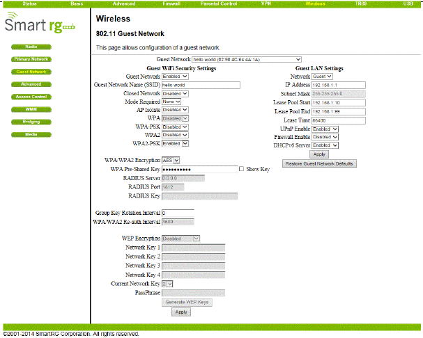
Figure 42 Guest Network configuration
The page allows you to configure a secondary guest network on the wireless
interface. This network is isolated from the LAN. Any clients that associate with the
guest network SSID will be isolated from the private LAN and can only communicate
with WAN hosts. Most of the configuration points on the guest network page are
identical to those on the Primary Network page. A few extras are explained below.
DHCP Server:
Enables the DHCP server to gives out leases to guest network clients from the
specified lease pool. If the DHCP server is disabled, guest network STAs need to be
assigned static IP addresses.
IP Address:
This specifies the gateway IP relayed to guest clients in DHCP lease offers.
Subnet Mask:
This specifies the subnet mask for the guest network.
Lease Pool Start:
SR804N Cable Modem User Manual
45
This specifies the starting IP address for the guest network lease pool.
Lease Pool End:
This specifies the ending IP address for the guest network lease pool.
Lease Time:
This specifies the lease time for the guest network lease pool, once the CMRG
completes WAN provisioning.
5.7.4 Advanced
Choose Wireless > Advanced to display the following page.
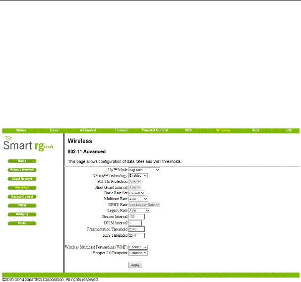
Figure 43 Advanced setting
This page allows you to configure advanced wireless settings.
54g™ Mode:
Sets the network mode. Choices are 54g Auto, 54g Performance, 54g LRS, and
802.11b Only. 54g Auto accepts 54g, 802.11g, and 802.11b clients, but optimizes
performance based on the type of clients connected. 54g Performance accepts only
54g™ clients and provides the highest throughout; nearby 802.11b networks may
have degraded performance. 54g LRS interoperates with the widest variety of
54g™, 802.11g, and 802.11b clients. 80211b.accepts only 802.11b clients.
54g™ Protection:

SR804N Cable Modem User Manual
46
In Auto mode the AP will use RTS/CTS protection to improve 802.11g performance in
mixed 802.11g + 802.11b networks. Turn protection Off to maximize 802.11g
throughput under most conditions.
Xpress Technology:
Enable Broadcom proprietary method of block frame acknowledgement for 802.11g
frames. This feature may improve throughput, but may cause problems.
Afterburner Technology
This feature removes the need for the acknowledgement of data frames. It may
improve throughput, but may cause problems.
802.11n Protection:
Similar to 54g protection except it applies to 802.11n devices.
Basic Rate Set:
Determines which rates are advertised as “basic” rates. Default uses the driver
defaults. Sets all available rates as basic rates.
Multicast Rate:
This is the rate at which you send out multicast packets to stations. Multicast packets
are not acknowledged.
NPHY Rate:
Choose 802.11n rate to be applied to all unicast packets.
Legacy Rate:
“N” mode must be off on the “radio” webpage for this control to be active. When
active the user can force the rate in which the AP will operate.
Beacon Interval:
Sets the beacon interval in milliseconds for the AP. The default is 100, which is fine
for nearly all applications.
DTIM Interval:
Sets the wakeup interval for clients in power-save mode. When a client is running in
power save mode, lower values provide higher performance but result in decreased
client battery life, while higher values provide lower performance but result in
increased client battery life.
Fragmentation Threshold:
Sets the fragmentation threshold. Packets exceeding this threshold will be
fragmented into packets no larger than the threshold before packet transmission.
RTS Threshold:
SR804N Cable Modem User Manual
47
Sets the RTS threshold. Packets exceeding this threshold will cause the AP to
perform an RTS/CTS exchange to reserve the wireless medium before packet
transmission.
5.7.5 Access Control
Choose Wireless > Access Control to display the following page.
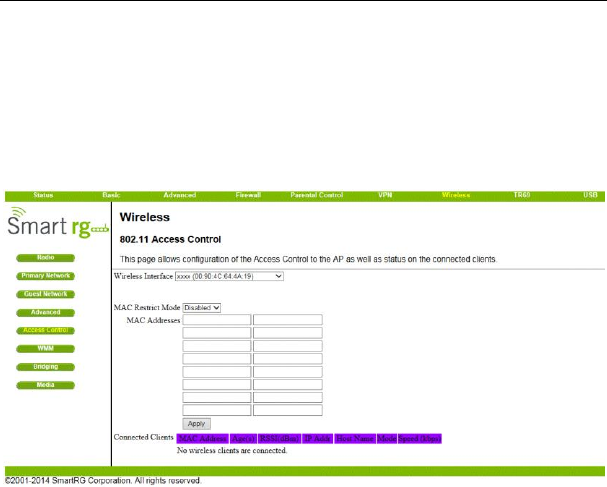
Figure 44 Access Control setting
This page allows you to control which wireless clients can access your wireless
network. It also provides information about wireless clients connected to your access
point.
MAC Restrict Mode:
Selects whether wireless clients with the specified MAC address are allowed or
denied wireless access. To allow all clients, select Disabled.
MAC Addresses:
A list of wireless client MAC addresses to allow or deny based on the Restrict Mode
setting. Valid input MAC address formats are XX:XX:XX:XX:XX:XX and
XX-XX-XX-XX-XX-XX.
Connected Clients:
A list of connected wireless clients. When a client connects (associates) to the
network, it is added to the list; when a client leaves (disassociates) from the network,
it is removed from the list. For each client, the age (in seconds), estimated average
SR804N Cable Modem User Manual
48
receive signal strength (in dBm), IP address, and host name are presented. The age
is the amount of time elapsed since data was transmitted to or received from the
client.
5.7.6 WMM
Choose Wireless > WMM to display the following page.
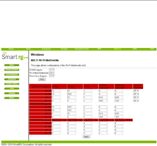
Figure 45 WMM configuration
This page allows you to configure WiFi Multi-Media (WMM). WMM is an
implementation of Quality of Service (Qos) which is defined by the IEEE standard
802.11e.
WMM Support:
Sets WMM support. Choices are Auto, On, or Off. If enabled (Auto or On), the WME
Information Element is included in beacon frame.
No-Acknowledgement:
Sets No-Acknowledgement support. Choices are On or Off. When enabled,
acknowledgments for data are not transmitted.
Power Save Support:
SR804N Cable Modem User Manual
49
Sets Power Save support. Choices are On or Off. When Power Save is enabled, the
AP queues packets for STAs that are in power-save mode. Queued packets are
transmitted when the STA notifies AP that it has left power-save mode.
EDCA AP Parameters:
Specifies the transmit parameters for traffic transmitted from the AP to the STA for the
four Access Categories: Best Effort (AC_BE), Background (AC_BK), Video (AC_VI),
and Voice (AC_VO). Transmit parameters include Contention Window (CWmin and
CWmax), Arbitration Inter Frame Spacing Number (AIFSN), and Transmit Opportunity
Limit (TXOP Limit).
There are also two AP-specific settings: Admission Control and Discard Oldest First.
Admission control specifies if admission control is enforced for the Access Categories.
Discard Oldest First specifies the discard policy for the queues. On discards the
oldest first; Off discards the newest first.
EDCA STA Parameters:
Specifies the transmit parameters for traffic transmitted from the STA to the AP for the
four Access Categories: Best Effort (AC_BE), Background (AC_BK), Video (AC_VI),
and Voice (AC_VO). Transmit parameters include Contention Window (CWmin and
CWmax), Arbitration Inter Frame Spacing Number (AIFSN), and Transmit Opportunity
Limit (TXOP Limit).
5.7.7 Bridging
Choose Wireless > Bridging to display the following page.
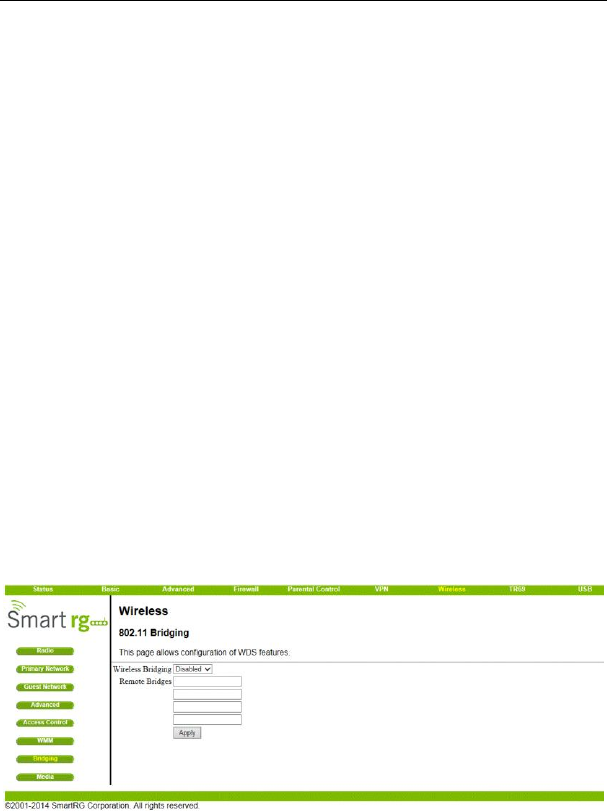
Figure 46 Bridging setting
SR804N Cable Modem User Manual
50
This page allows you to configure wireless bridging, which is also known as Wireless
Distribution System (WDS). Bridging allows you connect multiple wireless access
points together to form a single network using wireless point-to-point links.
Wireless Bridging:
This setting enables or disables wireless bridging.
Remote Bridges:
Table of remote bridge MAC addresses authorized to establish a wireless bridge.
Up to 4 remote bridges may be connected. Typically, you will also have to enter your
AP‟s MAC address (see section 0) on the remote bridge, too.
5.7.8 Media
Choose Wireless > Media and the follow page will be shown.
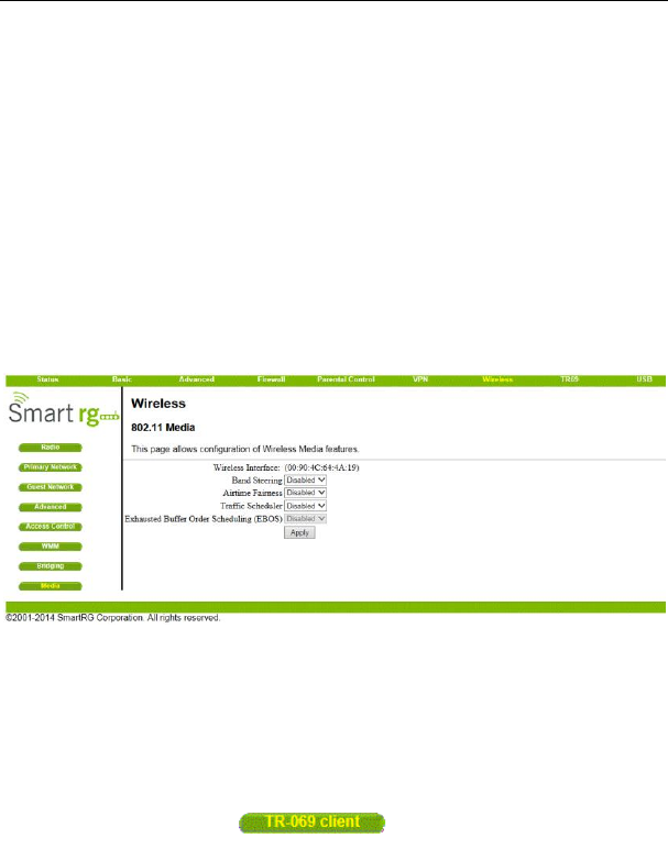
Figure 47 Media setting
This page allows configuration of Wireless Media features.
5.8 TR69
Choose TR69 and the submenus of TR69 are shown as below.
Figure 48 Submenus of TR69
SR804N Cable Modem User Manual
51
5.8.1 TR-069 client
Choose TR69 > TR-069 client to display the following page.
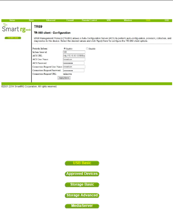
Figure 49 TR-069 client configuration
WAN Management Protocol (TR-069) allows a Auto-Configuration Server (ACS) to
perform auto-configuration, provision, collection, and diagnostics to this device.
Select the desired values and click 'Apply/Save' to configure the TR-069 client
options.
5.9 USB
Choose USB and the submenus of USB are shown as below.
Figure 50 Submenus of USB
SR804N Cable Modem User Manual
52
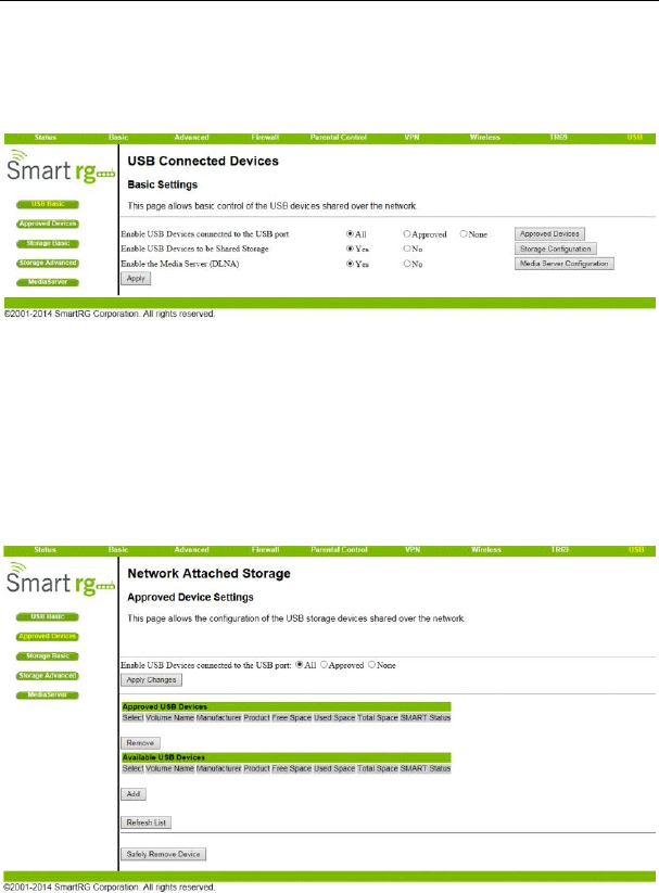
5.9.1 USB Basic
Choose USB > USB Basic to display the following page.
Figure 51 USB Basic setting
This page allows you to configure Linux based servers. The buttons on the right side
of the page are short cuts to the buttons on the left side frame.
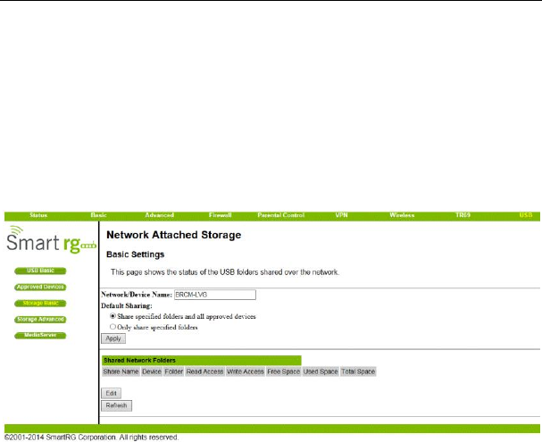
5.9.2 Approved Devices
Choose USB > Approved Devices to display the following page.
Figure 52 Approved Devices setting
SR804N Cable Modem User Manual
53
This page allows you to choose if any USB storage device plugged into the modem
can be used or only approved devices. If approved device is selected then each
device must be manually approved on this page. USB storage devices can be safely
removed after selecting the Safely Remove Device button. The user will be asked
which device they want to remove.
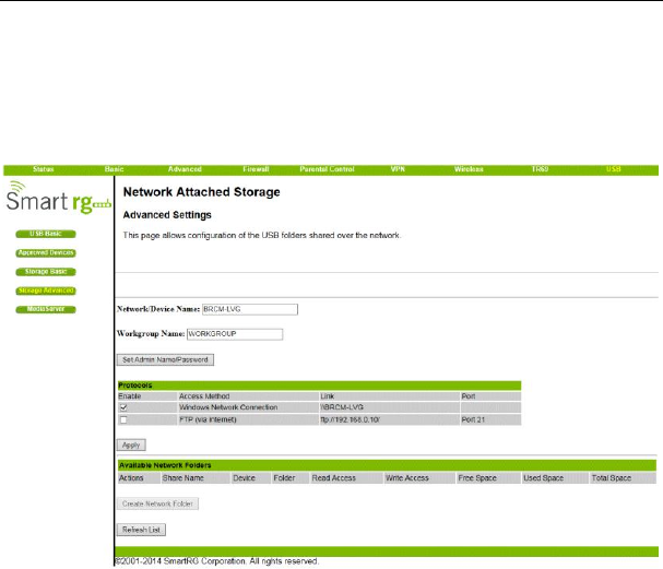
5.9.3 Storage Basic
Choose USB > Storage Basic to display the following page.
Figure 53 Storage Basic setting
This page allows you to configure the device name and what folders should be
shared.
5.9.4 Storage Advanced
Choose USB > Storage Advanced to display the following page.
SR804N Cable Modem User Manual
54
Figure 54 Storage Advanced setting
This page allows you to configure the device name. Additionally the workgroup name
can is configured here. The Windows Network and FTP support can be enabled or
disabled on this page. The IP address displayed in the link field is the Linux IP stack
address that should be used for the FTP server address in the FTP clients.
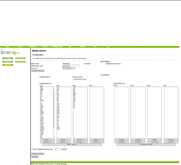
5.9.5 Media Server
Choose USB > Media Server to display the following page.
SR804N Cable Modem User Manual
55
Figure 55 Media Server setting
This page allows you to configure the DLNA media server. The media server name
and the file names that will be scanned on the USB storage devices are configured
using this page. If desired the media Server can scan the device periodically to check
for new files.

SR804N Cable Modem User Manual
56
6 Q&A
(1) Q: Why all the indicators are off?
A: Check the following:
The connection between the power adaptor and the power socket.
The status of the power switch.
(2) Q: Why the Ethernet indicator is off?
A: Check the following:
The connection between the Cable Modem and your computer, hub, or
switch.
The running status of your PC, hub, or switch.
(3) Q: Why the ONLINE indicator is off?
A: Check CM DS/US LED is on. Check the connection between the Cable
Line and the wall HFC.
FCC Statement
This device complies with Part 15 of the FCC Rules.
Operation is subject to the following two conditions: (1) This device may not cause
harmful interference, and (2) This device must accept any interference received,
including interference that may cause undesired operation.
The grantee is not responsible for any changes or modifications not expressly
approved by the party responsible for compliance. Such modifications could void
the user‟s authority to operate the equipment.
This equipment has been tested and found to comply with the limits for a Class B
digital device, pursuant to part 15 of the FCC Rules. These limits are designed to
provide reasonable protection against harmful interference in a residential
installation. This equipment generates, uses and can radiate radio frequency
energy and, if not installed and used in accordance with the instructions, may
cause harmful interference to radio communications. However, there is no
guarantee that interference will not occur in a particular installation. If this
equipment does cause harmful interference to radio or television reception, which
can be determined by turning the equipment off and on, the user is encouraged to
try to correct the interference by one or more of the following measures:
—Reorient or relocate the receiving antenna.

SR804N Cable Modem User Manual
57
—Increase the separation between the equipment and receiver.
—Connect the equipment into an outlet on a circuit different from that to which the
receiver is connected.
—Consult the dealer or an experienced radio/TV technician for help.
This transmitter must not be co-located or operating in conjunction with any other
antenna or transmitter. This equipment should be installed and operated with a
minimum distance of 20 centimeters between the radiator and your body.
IC Statement
This device complies with Industry Canada licence‐exempt RSS standard(s).
Operation is subject to the following two conditions: (1) this device may not cause
interference, and (2) this device must accept any interference, including
interference that may cause undesired operation of the device.
CAN ICES-3(B)/NMB-3(B)
Le présent appareil est conforme aux CNR d'Industrie Canada applicables aux
appareils radio exempts de licence. L'exploitation est autorisée aux deux
conditions suivantes:
(1) il ne doit pas produire de brouillage et
(2) l‟ utilisateur du dispositif doit étre prêt à accepter tout brouillage radioélectrique
reçu, même si ce brouillage est susceptible de compromettre le
fomctionnement du dispositif.
Cet émetteur ne doit pas être Co-placé ou ne fonctionnant en même temps
qu'aucune autre antenne ou émetteur. Cet équipement devrait être installé et
actionné avec une distance minimum de 20 centimètres entre le radiateur et
votre corps.