SmartSense by Digi TM-ZP05X The product is a 2.4 GHz module capable of transmitting sensor measurements to a gateway. User Manual
Schechter Tech LLC DBA TemperatureAlert The product is a 2.4 GHz module capable of transmitting sensor measurements to a gateway.
Contents
- 1. User Manual.pdf
- 2. User manual_ZPoint OEM Module Manual v4.pdf
User Manual.pdf
TM-ZP050X Modules
PRIVATE AND CONFIDENTIAL
U.S. Patent Nos. 7,952,485; 8,547,226; 8,248,252; 8,599,012; 8,779,926; and 9,092,967. Additional patents pending.
© 2015 Temperature@lert. All Rights Reserved. Doc 8.7.1.2015.002
ZPoint OEM Modules
The TM-ZP05X is the 8th generation of advanced wireless communication modules from
Temperature@lert and the first module on the market to feature Temperature@lert’s patented
private sensor network management system that enables secure turn-key wireless sensor network
deployment.
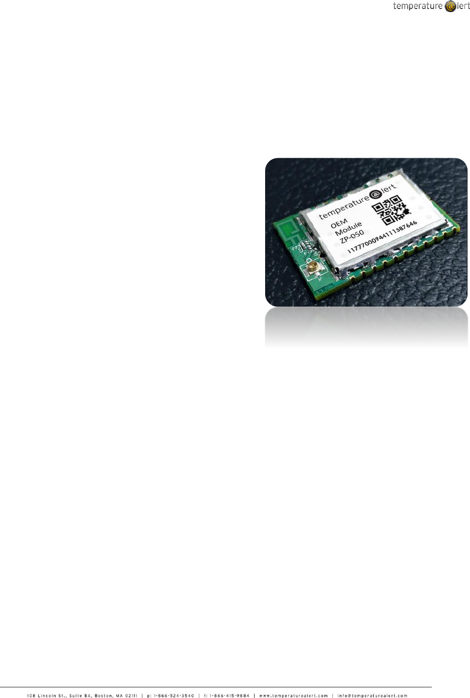
As with all Temperature@lert ZPoint devices, the
TM-ZP05X series devices are designed to be
easily integrated into designs without the need for
RF or embedded expertise. Using the latest
version of Temperature@lert’s ZPoint wireless
communications platform, the TM-ZP05X family of
modules allows designers to add wireless remote
monitoring and sensor network management
technology without complex software engineering.
Modules send data via cellular or Ethernet
gateways back to Temperature@lert’s cloud-
based sensor management and analytics system.
Overview
The Temperature@lert TM-ZP05X modules are low
power 2.4GHz wireless transceivers based on the
ARM Coretex M3 SoC.
Available both in PCB trace antenna and external
antenna via U.FL connector form, Temperature@lert
modules have been designed to be integrated into
any devices without the need for RF experience and
expertise. The TM-ZP05X enables one to add
powerful wireless networking and private sensor
network management to any product and quickly
bring it to market.
The Temperature@lert unique serial command
interface allows designers to quickly integrate
wireless technology without complex engineering.
For custom application development, the TM-ZP05X
series integrates with ease into Temperature@lert’s
proven remote monitoring cloud platform.
Suggested Applications
Connected Gauges
Private Sensor Networks
Industrial Monitoring Solutions
M2M Wireless Solutions
Data Center Monitoring
Energy Monitoring
Facility and Business Monitoring
Production and Manufacturing Solutions
Supply Chain
Enterprise Solutions
White Label Solutions
API Integration Services
Custom Hardware & Software
Analytics Solutions
TM-ZP050X Modules
PRIVATE AND CONFIDENTIAL
U.S. Patent Nos. 7,952,485; 8,547,226; 8,248,252; 8,599,012; 8,779,926; and 9,092,967. Additional patents pending.
© 2015 Temperature@lert. All Rights Reserved. Doc 8.7.1.2015.002
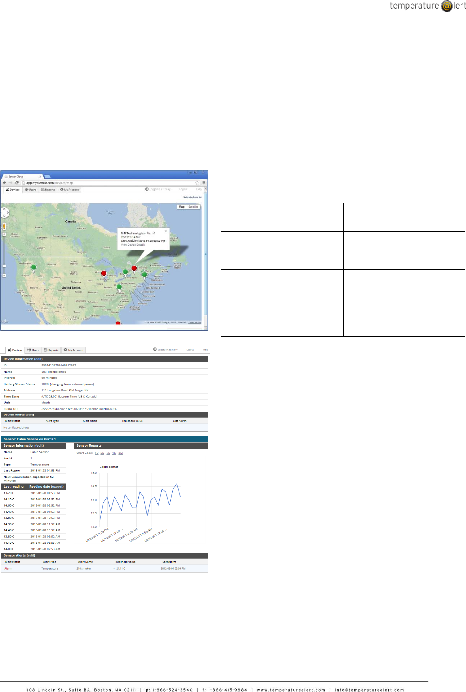
Sensor Cloud
Data collected resides in Temperature@lert’s
Sensor Cloud web-based management system
and includes native iPhone and Android apps
as well as a rich API for interoperability and
enterprise integration. Optional white labeling
of software and support options are available.
Integration
The ZP-05X modules require less than 2500mAh of
charge to operate for up to 5 years. Modules are easily
integrated into existing systems via TTL serial, I2C,
SPI, 1-Wire, or other customer-defined serial
interfaces. Please contact sales for additional
information.
Module Features
Small form factor, SMT module
35mm x 25mm
2 antenna options: integrated
PCB trace antenna or U.F.L.
coaxial connector
Variable report frequency
Wide supply voltage range (2.1
to 3.6V)
Integrated high accuracy
temperature sensor
Operating temperature range:
-40°C to +85°C
Additional external sensor
inputs
Radio approvals – CE, IC, FCC
Works with Temperature@lert
cellular and Ethernet gateways
Store and Forward data loss
prevention
5 year battery life
1000’ range (line of sight)
128-bit AES encryption
Optional certificate based
security
TM-ZP050X Modules
PRIVATE AND CONFIDENTIAL
U.S. Patent Nos. 7,952,485; 8,547,226; 8,248,252; 8,599,012; 8,779,926; and 9,092,967. Additional patents pending.
© 2015 Temperature@lert. All Rights Reserved. Doc 8.7.1.2015.002
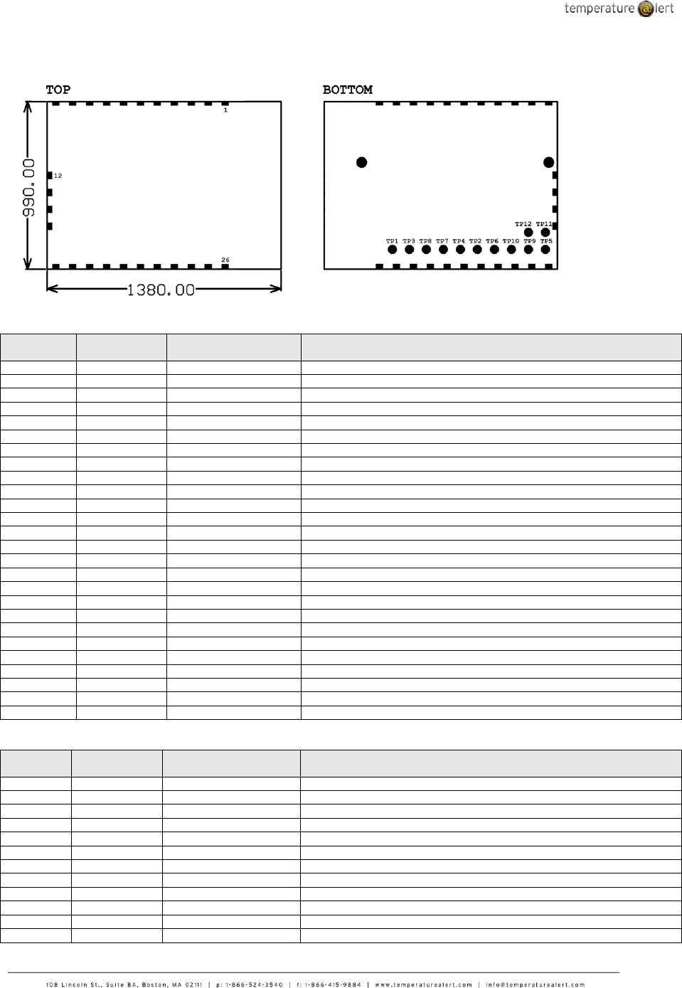
Pin Out
Castellated Pads
Castellated
Pin No.
Name
Type
Description
1
GND
Power
Ground
2
GND
Power
Ground
3
T@DIG1
I/O
Digital line for T@ sensor / GPIO
4
T@ANA1
Analog In
Analog line for T@ sensor / GPIO / Analog input
5
T@DIG2
I/O
Digital line for T@ sensor / GPIO
6
T@ANA2
Analog In
Analog line for T@ sensor / GPIO / Analog input
7
T@PWR
Output
T@ sensor power
8
T@PWR
Output
T@ sensor power
9
SOUT1
I/O
SPI Master MOSI / I2C Master SDA / UART TXD / GPIO
10
SIN1
I/O
SPI Master MISO / I2C Master SCL / UART RXD / GPIO
11
SCLK1
I/O
SPI Master SCLK / GPIO
12
SIN2
I/O
Internal SPI (NC) / SPI Master MISO / I2C Master SDA / GPIO
13
SOUT2
I/O
Internal SPI (NC) / SPI Master MOSI / GPIO
14
SCLK1
I/O
Internal SPI (NC) / SPI Master SCLK / I2C Master SCL / GPIO
15
VCC
I/O
Positive supply, 2.1 – 3.6V
16
TRACEDATA2
Output
JTAG trace data
17
TRACEDATA3
Output
JTAG trace data
18
JCLK
Input
JTAG clock
19
JTDO
Output
JTAG data out
20
JTDI
Input
JTAG data in
21
JTMS
Input
JTAG test mode select
22
GND
Power
Ground
23
nRESET
Input
Active-low reset
24
TRACEDATA1
Output
JTAG trace data
25
GND
Power
Ground
26
VCC
Power
Positive supply, 2.1 – 3.6V
Bottom Test Points
Bottom
Test Point
Name
Type
Description
TP1
VCC
Power
Positive supply, 2.1 – 3.6V
TP2
JTDO
Output
JTAG data out
TP3
TRACEDATA1
Output
JTAG trace data
TP4
JTDI
Input
JTAG data in
TP5
GND
Power
Ground
TP6
JCLK
Input
JTAG clock
TP7
JTMS
Input
JTAG test mode select
TP8
nRESET
Input
Active-low reset
TP9
TRACEDATA2
Output
JTAG trace data
TP10
TRACEDATA3
Output
JTAG trace data
TP11
SOUT1
I/O
SPI Master MOSI / I2C Master SDA / UART TXD / GPIO
TP12
SIN1
I/O
SPI Master MISO / I2C Master SCL / UART RXD / GPIO

TM-ZP050X Modules
PRIVATE AND CONFIDENTIAL
U.S. Patent Nos. 7,952,485; 8,547,226; 8,248,252; 8,599,012; 8,779,926; and 9,092,967. Additional patents pending.
© 2015 Temperature@lert. All Rights Reserved. Doc 8.7.1.2015.002
Regulator Notices
This device complies with Part 15 of the FCC Rules. Operation is subject to the following two conditions: (1) this device may not
cause harmful interference, and (2) this device must accept any interference received, including interference that may cause
undesired operation.
Changes or modifications not expressly approved by Temperature@lert could void the user’s authority to operate the equipment.
The final end product must be labeled in a visible area with the following: Contains Transmitter Module FCC ID: XYZ (IC: XYZ)” or
“Contains FCC ID: SZ9TM-ZP05X IC: 10940A- TMZP05X” or similar wording. Label must also contain brand/trade name and model
number of the product.
This equipment has been tested and found to comply with the limits for a Class B digital device, pursuant to Part 15 of the FCC
Rules. These limits are designed to provide reasonable protection against harmful interference in a residential installation. This
equipment generates uses and can radiate radio frequency energy and, if not installed and used in accordance with the instructions,
may cause harmful interference to radio communications. However, there is no guarantee that interference will not occur in a
particular installation. If this equipment does cause harmful interference to radio or television reception, which can be determined by
turning the equipment off and on, the user is encouraged to try to correct the interference by one of the following measures:
- Reorient or relocate the receiving antenna.
- Increase the separation between the equipment and receiver.
- Connect the equipment into an outlet on a circuit different from that to which the receiver is connected.
- Consult the dealer or an experienced radio/TV technician for help.
This device complies with Part 15 of the FCC Rules. Operation is subject to the following two conditions: (1) This device may not
cause harmful interference, and (2) this device must accept any interference received, including interference that may cause
undesired operation.
FCC Caution: Any changes or modifications not expressly approved by the party responsible for compliance could void the user's
authority to operate this equipment.
To comply with FCC’s and Industry Canada’s RF radiation exposure limits for general population/uncontrolled exposure, the
antenna(s) used for this transmitter must be installed to provide a separation distance of at least 20 cm from all persons and must
not be collocated or operating in conjunction with any other antenna or transmitter.
This device complies with Industry Canada licence-exempt RSS standard(s). Operation is subject to the following two conditions: (1)
this device may not cause interference, and (2) this device must accept any interference, including interference that may cause
undesired operation of the device.
Le présent appareil est conforme aux CNR d'Industrie Canada applicables aux appareils radio exempts de licence. L'exploitation est
autorisée aux deux conditions suivantes : (1) l'appareil ne doit pas produire de brouillage, et (2) l'utilisateur de l'appareil doit
accepter tout brouillage radioélectrique subi, même si le brouillage est susceptible d'en compromettre le fonctionnement.
This radio transmitter has been approved by Industry Canada to operate with the antenna types listed below with the maximum
permissible gain and required antenna impedance for each antenna type indicated. Antenna types not included in this list, having a
gain greater than the maximum gain indicated for that type, are strictly prohibited for use with this device.
Le présent émetteur radio a été approuvé par Industrie Canada pour fonctionner avec les types d'antenne énumérés ci-dessous et
ayant un gain admissible maximal et l'impédance requise pour chaque type d'antenne. Les types d'antenne non inclus dans cette
liste, ou dont le gain est supérieur au gain maximal indiqué, sont strictement interdits pour l'exploitation de l'émetteur.
The device is approved to work with an external 1/2 wavelength dipole SMA-RP antenna with maximum gain of 2.45dbi or the
internal inverted F trance antenna with maximum gain of 1dBi.
Under Industry Canada regulations, this radio transmitter may only operate using an antenna of a type and maximum (or lesser)
gain approved for the transmitter by Industry Canada. To reduce potential radio interference to other users, the antenna type and its
gain should be so chosen that the equivalent isotropically radiated power (e.i.r.p.) is not more than that necessary for successful
communication.
Conformément à la réglementation d'Industrie Canada, le présent émetteur radio peut fonctionner avec une antenne d'un type et
d'un gain maximal (ou inférieur) approuvé pour l'émetteur par Industrie Canada. Dans le but de réduire les risques de brouillage
radioélectrique à l'intention des autres utilisateurs, il faut choisir le type d'antenne et son gain de sorte que la puissance isotrope
rayonnée équivalente (p.i.r.e.) ne dépasse pas l'intensité nécessaire à l'établissement d'une communication satisfaisante.