SmartSense by Digi TMWIFI440Z Ethernet Gateway User Manual Ethernet Gateway user guide v4 22
Schechter Tech LLC DBA TemperatureAlert Ethernet Gateway Ethernet Gateway user guide v4 22
User manual_Ethernet-Gateway_user_guide_v4.22.pdf

186 Lincoln Street, 8th Floor, Boston MA 02111 | p: (866) 524-3540 | f: (866) 415-9884 | www.tempalert.com | info@tempalert.com
! !
Summer&
17#
Ethernet Gateway
User Manual
#
#
#

TempAlert Ethernet Gateway
User Manual
www.tempalert.com
Tel: (866) 524-3540
Page 2 of 22 TempAlert Ethernet Gateway User Guide v 4.22
186 Lincoln Street, 8th Floor, Boston MA 02111 | p: (866) 524-3540 | f: (866) 415-9884 | www.tempalert.com | info@tempalert.com
Table of Contents
INTRODUCTION 3
AT A GLANCE 4
ETHERNET GATEWAY SETUP VIA DHCP 5
ETHERNET GATEWAY SETUP VIA STATIC IP 6
JACKS, BUTTONS, AND PORTS 9
TROUBLESHOOTING THE ETHERNET GATEWAY 10
TROUBLESHOOTING NETWORK ISSUES 10
LED INDICATOR LIGHTS 10
NO READINGS 13
TEMPERATURE READING IS A FEW DEGREES WARMER OR COLDER THAN EXPECTED 14
USING WIRELESS SENSORS 15
TROUBLESHOOTING THE WIRELESS SENSOR 17
LED INDICATOR LIGHTS 18
IMPORTANT USAGE INFORMATION 19
CONTACT US 22
!

TempAlert Ethernet Gateway
User Manual
www.tempalert.com
Tel: (866) 524-3540
Page 3 of 22 TempAlert Ethernet Gateway User Guide v 4.22
186 Lincoln Street, 8th Floor, Boston MA 02111 | p: (866) 524-3540 | f: (866) 415-9884 | www.tempalert.com | info@tempalert.com
Introduction
Thank you for choosing TempAlert’s Ethernet Gateway as your preferred monitoring solution!
Follow this user manual for proper use of your new system. Please keep this guide handy for
future operational reference.
# #
TempAlert Ethernet Gateway
User Manual
www.tempalert.com
Tel: (866) 524-3540
Page 4 of 22 TempAlert Ethernet Gateway User Guide v 4.22
186 Lincoln Street, 8th Floor, Boston MA 02111 | p: (866) 524-3540 | f: (866) 415-9884 | www.tempalert.com | info@tempalert.com
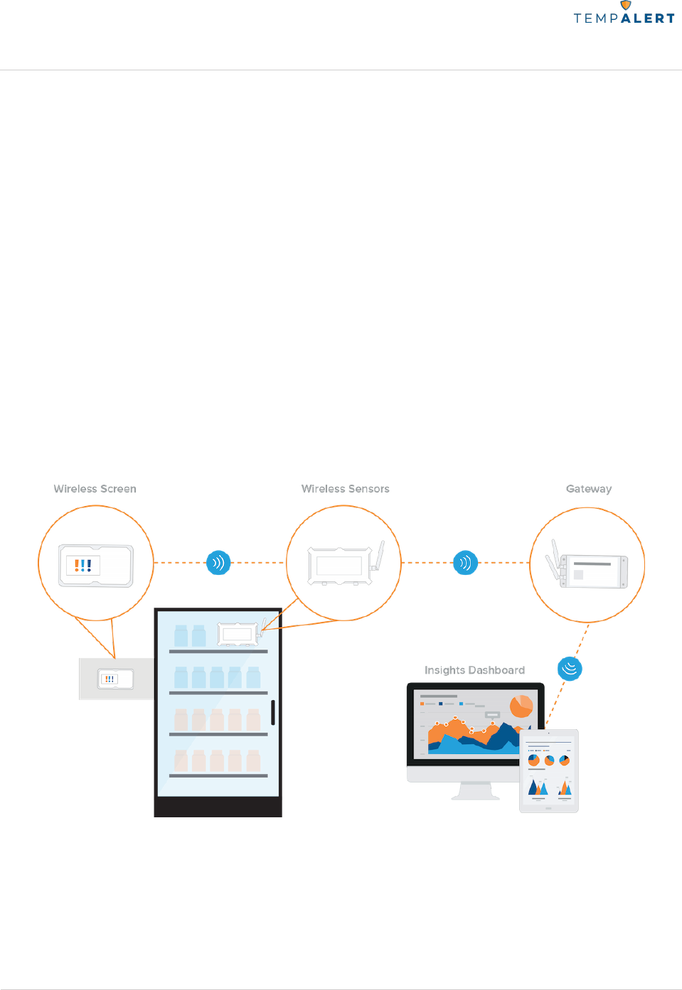
At a Glance
The Ethernet Gateway (Model # TM-WIFI440-Z) is a remote monitoring system that connects
directly to the Internet through Ethernet cable connection (DHCP or Static IP). Connect
Wireless Sensors to the Ethernet Gateway to remotely monitor temperature, humidity, and
more, and configure alerts when conditions fall outside of your set ranges.
The Ethernet Gateway can use either wired sensors (connected directly to the unit) or wireless
sensors. Each Ethernet Gateway unit can be linked up to 15 wireless sensors and up to four
wired sensors. Each sensor reading is transmitted to our monitoring dashboard: InsightsTM; and
if our monitoring dashboard does not hear from your gateway(s), you will be notified via
Missed Report alerts as part of our system Health Check feature.
TempAlert Ethernet Gateway
User Manual
www.tempalert.com
Tel: (866) 524-3540
Page 5 of 22 TempAlert Ethernet Gateway User Guide v 4.22
186 Lincoln Street, 8th Floor, Boston MA 02111 | p: (866) 524-3540 | f: (866) 415-9884 | www.tempalert.com | info@tempalert.com
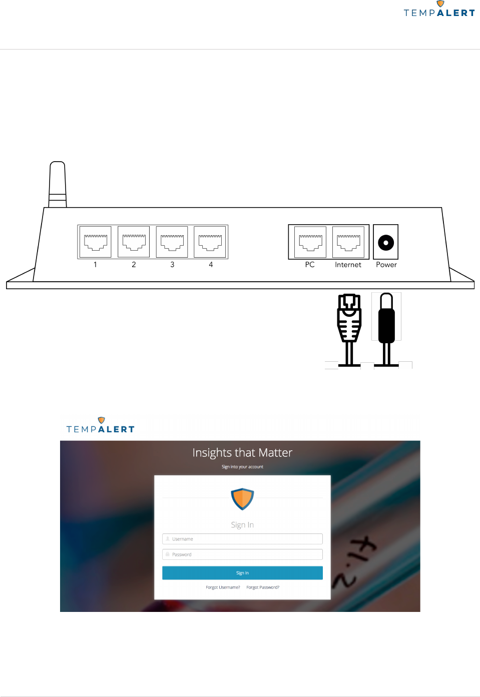
Ethernet Gateway Setup via DHCP
1. Connect the Ethernet Gateway to power using the power adapter and cable included in the
product box. You will see a blue light flashing as the device boots up. Connect the Internet
router to the Internet port on the Ethernet Gateway using an Ethernet cable (not included). You
should see a single blink on both LAN and Internet after a successful transmission.
2. Open a web browser on your computer and go to insights.tempalert.com. Once the page
loads, enter the login credentials provided to you at the time of purchase.
3. Set up your preferences, device and sensor alerts. For more information, please view the
InsightsTM User Manual for more set up help, tips, and suggestions for optimal performance.
TempAlert Ethernet Gateway
User Manual
www.tempalert.com
Tel: (866) 524-3540
Page 6 of 22 TempAlert Ethernet Gateway User Guide v 4.22
186 Lincoln Street, 8th Floor, Boston MA 02111 | p: (866) 524-3540 | f: (866) 415-9884 | www.tempalert.com | info@tempalert.com
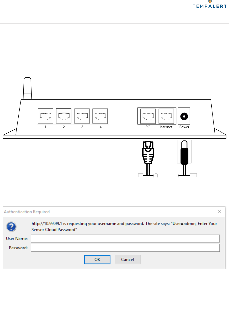
Ethernet Gateway Setup via Static IP
1. Connect the Ethernet Gateway to power using the power adapter and cable included in the
product box. You will see a blue light flashing as the device boots up. Connect the Ethernet
Gateway from its PC port to a computer’s Ethernet port using an Ethernet cable (not included).
2. Open a web browser on your computer and go to 10.99.99.1. Once the page loads, enter
the login credentials. Username is admin and the password is provided on the device’s label
found on the side opposite to the LEDs.
TempAlert Ethernet Gateway
User Manual
www.tempalert.com
Tel: (866) 524-3540
Page 7 of 22 TempAlert Ethernet Gateway User Guide v 4.22
186 Lincoln Street, 8th Floor, Boston MA 02111 | p: (866) 524-3540 | f: (866) 415-9884 | www.tempalert.com | info@tempalert.com
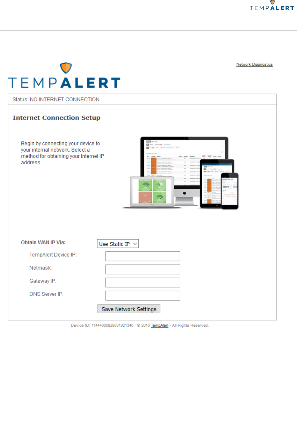
3. Set “Obtain Wan IP Via” to “Use Static IP” and input your network settings then finally click
“Save Network Settings”.
4. Connect the Internet router to the Internet port on the Ethernet Gateway using an Ethernet
cable (not included). You should see a single blink on both LAN and Internet after a successful
transmission.

TempAlert Ethernet Gateway
User Manual
www.tempalert.com
Tel: (866) 524-3540
Page 8 of 22 TempAlert Ethernet Gateway User Guide v 4.22
186 Lincoln Street, 8th Floor, Boston MA 02111 | p: (866) 524-3540 | f: (866) 415-9884 | www.tempalert.com | info@tempalert.com
5. Open a web browser on your computer and go to insights.tempalert.com. Once the page
loads, enter the login credentials provided to you at the time of purchase.
6. Set up your preferences, device and sensor alerts. For more information, please view the
InsightsTM User Manual for more set up help, tips, and suggestions for optimal performance.

TempAlert Ethernet Gateway
User Manual
www.tempalert.com
Tel: (866) 524-3540
Page 9 of 22 TempAlert Ethernet Gateway User Guide v 4.22
186 Lincoln Street, 8th Floor, Boston MA 02111 | p: (866) 524-3540 | f: (866) 415-9884 | www.tempalert.com | info@tempalert.com
Jacks, Buttons, and Ports
• Sensor Ports 1, 2, 3, and 4
o Accepts any RJ12 type sensor made for the Ethernet Gateway.
• Power Jack
o The Ethernet Gateway can be powered by connecting a 5V 1A power supply to
a North American electrical outlet. The power jack accepts DC 2.1/6.3mm
coaxial power connectors of 12VDC at 1A.
• Reset Button
o The reset button is located in a small pinhole on the bottom of the Ethernet
Gateway below the device ID label. Pressing and holding the reboot button for
20 seconds will factory reset the device to its DHCP configuration.
• PC Port
o This connection is only used for initial setup for Static IP using the web GUI of
10.99.99.1 only unless pre-configured by the manufacturer. Connecting from
this port will cause the Gateway to act as a DHCP server and may cause
problems on your network.
• Internet Port
o This Ethernet port is used for a permanent hardwire connection between your
Ethernet Gateway and Internet router.
Operating Guidelines
• Placement
o The unit should be placed indoors on a flat and level surface. The unit can be
mounted vertically on a wall or other surface with additional user supplied
hardware (such as screws, mounting tape, or industrial strength Velcro).
• Using Wired Sensors
o When using the wired sensors, care should be taken so that the cable is
managed in such a way that it is not accidentally unplugged from the unit. If the
external sensor is removed from the unit, the unit will not be able to monitor the
environmental conditions.
• Wireless Reception
o The Ethernet Gateway has one antenna. This antenna allows for wireless
connection to TempAlert wireless sensors.
• Powering the Unit
o We recommend that the unit be connected to an uninterruptible power supply
(UPS) or battery backup. If power to the Ethernet Gateway is lost, readings from

TempAlert Ethernet Gateway
User Manual
www.tempalert.com
Tel: (866) 524-3540
Page 10 of 22 TempAlert Ethernet Gateway User Guide v 4.22
186 Lincoln Street, 8th Floor, Boston MA 02111 | p: (866) 524-3540 | f: (866) 415-9884 | www.tempalert.com | info@tempalert.com
hardwired sensors stored in the local memory will be lost and the Gateway will
not be able to record temperatures and send alarms. We recommend
disconnecting power for 10 seconds or more before powering up the Gateway
again. Passive PoE can be used as an alternative means of power. It is
recommended to use the Passive PoE injectors purchased directly from us to
ensure proper performance. The Gateway is not compatible with Active PoE.
Troubleshooting the Ethernet Gateway
LED Indicator Lights
Use the following table to troubleshoot your Ethernet Gateway
LED
No Blink
1 Blink
2 Blinks
3 Blinks
4 Blinks
Flashing
LAN
No network
connection
Good
connection to
the network
Attempting to
send wireless
sensor readings
Attempting
to send local
Gateway
readings
Internet
No
connection to
Insights™
Last
transmission to
Insights™ was
successful
Activity
No wired
sensors are
connected to
the Gateway
Wireless
sensor(s)
connected
Ethernet
starting up
Failure
Incorrect
network
configuration
Gateway not
registered on
Insights™
Unable to
connect to
Insights™
server
Last
transmission
to Insights™
was
unsuccessful

TempAlert Ethernet Gateway
User Manual
www.tempalert.com
Tel: (866) 524-3540
Page 11 of 22 TempAlert Ethernet Gateway User Guide v 4.22
186 Lincoln Street, 8th Floor, Boston MA 02111 | p: (866) 524-3540 | f: (866) 415-9884 | www.tempalert.com | info@tempalert.com
Troubleshooting Network Issues.
1. Connect the Ethernet Gateway to power using the power adapter and cable included in the
product box. You will see a blue light flashing as the device boots up. Connect the Ethernet
Gateway from its PC port to a computer’s Ethernet port using an Ethernet cable (not included).
2. Open a web browser on your computer and go to 10.99.99.1. Once the page loads, enter
the login credentials. Username is admin and the password is provided on the device’s label
found on the side opposite to the LEDs.
3. Click on the “network diagnostics” link found on the upper right of the page. You can sent
this log to your IT team and network administrator help find a resolution to your problem. !
Restoring Factory Defaults!
Performing a factory reset will restore the Gateway to its initial factory settings with DHCP
configuration. This will remove any changes made. A factory reset should only be used if all
other attempts to access the Gateway’s web GUI have failed.!
!
Steps to Factory Reset Ethernet Gateway:
1. Plug the Ethernet Gateway into a power source using the provided AC adapter.
2. Locate the pinhole on the underside of the Gateway. You'll need a pin or paper clip
in order to access the reset button.
3. Press and hold the reset button for 20 seconds then release. There will be no visual
indication of a reset.
4. Wait 90 seconds to allow the device to reboot before connecting to a PC if you are
looking to use Static IP configuration.
5. If you are using Static IP configuration, go to the web GUI 10.99.99.1 and you will
notice all factory settings have been restored to the factory defaults.
Unit Does Not Power On!
Check to make sure the unit is connected to wall power with the included power adapter or the
unit is connected to a Passive PoE connection with a power injector. Active PoE via powered
hub or switch is not supported. You must use a power injector if you choose to utilize PoE.
!

TempAlert Ethernet Gateway
User Manual
www.tempalert.com
Tel: (866) 524-3540
Page 12 of 22 TempAlert Ethernet Gateway User Guide v 4.22
186 Lincoln Street, 8th Floor, Boston MA 02111 | p: (866) 524-3540 | f: (866) 415-9884 | www.tempalert.com | info@tempalert.com
Cannot Connect to the Web Admin Interface!
Check Connections to Ports
Ensure that the unit is receiving power. For initial Static IP setup, ensure that the unit is
connected directly to your computer's Ethernet port via the jack labeled “PC”. Do not connect
the unit to a router, switch or hub for initial setup. After you connect the device to power, you'll
need to wait about 1 minute for the Ethernet Gateway to fully boot up.
!
Check the Computer's Ethernet Settings!
Check to be sure your computer's Ethernet adapter is set to obtain an IP address automatically
(DHCP). If this is the initial setup, your device is already set to use DHCP configuration.

TempAlert Ethernet Gateway
User Manual
www.tempalert.com
Tel: (866) 524-3540
Page 13 of 22 TempAlert Ethernet Gateway User Guide v 4.22
186 Lincoln Street, 8th Floor, Boston MA 02111 | p: (866) 524-3540 | f: (866) 415-9884 | www.tempalert.com | info@tempalert.com
Cannot Receive Email from Insights™
Verify that the test and alert messages are not being automatically sorted into your junk or
SPAM folder. You may need to whitelist the messages in your email client to prevent them
from being sent to your junk or SPAM folder. Please see your email client's documentation for
more details.
If you are using a distribution group, check if the group allows emails from outside your
company.!
No Readings
Ensure the Gateway has Started Up!
It is recommended that sensor probes are plugged in before powering the Ethernet Gateway
on. After you connect the power you'll need to wait about one minute for the Gateway to fully
startup. During this time, you may not see the web based admin site or you may not see any
readings on InsightsTM. After one minute, refresh the page and the sensor readings should start
appearing in your monitoring dashboard.!
!
Check Sensor Connections!
Ensure there is at least one sensor connected to the sensor ports on the side of the unit or at
least one wireless sensor is powered on. The unit does not have any built-in internal sensors.
Contact support if you are unable to view a reading with a sensor cable connected or unable to
view readings from a wireless sensor.

TempAlert Ethernet Gateway
User Manual
www.tempalert.com
Tel: (866) 524-3540
Page 14 of 22 TempAlert Ethernet Gateway User Guide v 4.22
186 Lincoln Street, 8th Floor, Boston MA 02111 | p: (866) 524-3540 | f: (866) 415-9884 | www.tempalert.com | info@tempalert.com
Temperature Reading is a Few Degrees Warmer or Colder than Expected
!
Check Sensor Position!
If the sensor is positioned near the exhaust fan or near a cold air fan. Micro-climates can cause
inaccurate readings. Our sensors are rated to be within ±0.5°C (±1°F) and can be NIST/ISO
certified by an accredited lab to ensure this reading accuracy. !
Comparing Against Our Sensors!
When comparing the temperature readings from our sensors to another thermometer or data
logger, it's important to be mindful of the following:!
!
1. The margin of error of the comparison tool: Many thermostats will have a much higher
margin of error than our sensors, ±0.5°C (±1°F).
2. The temperature gradient of the room, refrigerator, or any other placement is in three
dimensions: Measuring the temperature in one part of the location can yield different results
than in another part of the same location due to micro-climates.
3. Air temperature changes faster than the temperature of a large amount of liquid: Air
temperature in a refrigerator may rise dramatically when the door is opened, but the
temperature of the contents of the refrigerator will rise more slowly due to their increased
thermal mass. We recommend the use of a buffer vial (virtual or physical) to ensure proper
readings are obtained at all times.
4. IR guns measure surface temperature while our sensors measure ambient air temperature or
buffered temperatures.
#

TempAlert Ethernet Gateway
User Manual
www.tempalert.com
Tel: (866) 524-3540
Page 15 of 22 TempAlert Ethernet Gateway User Guide v 4.22
186 Lincoln Street, 8th Floor, Boston MA 02111 | p: (866) 524-3540 | f: (866) 415-9884 | www.tempalert.com | info@tempalert.com
Using Wireless Sensors
When using wireless sensors, please refer to below:
Setting Up the Hardware
Ensure the Ethernet Gateway is powered on. Once the gateway is powered on, it will attempt
to connect to Insights™. After a successful connection is made, the Ethernet Gateway will be
accessible wirelessly to the battery-powered Wireless Sensors.
To use a battery-powered wireless sensor, simply press and release the power button to turn
on the unit. The wireless sensor will turn on and begin searching for a gateway within its range
and transmit a reading to the cloud. The unit is operating correctly if you do NOT see the red
failure light blink.
Your Wireless Sensor node transmits sensor readings via 2.4GHz radio waves to the Ethernet
Gateway. In order for the unit to operate, it must be within range of a gateway (up to 300ft
with obstructions and up to 1000ft line of sight).
Turning on the Wireless Sensor
To use a battery-powered wireless sensor, simply press and release the power button to turn
on the unit. All lights will briefly light up and the unit will be turned on.
Turning off the Wireless Sensor
Wireless sensors are shipped in the Off mode. To power off the wireless sensor manually,
PRESS AND HOLD the power button for 5 seconds. During power down, you will see all lights
turn on and the status light will flash. When the lights start going off in order one by one, you
can release the power button. The unit is now powered off. While fully powered off, the unit
will not send or record any temperature readings at any time. All indicator lights will be off.
Pausing your Insights™ account does not power off the Wireless Sensor.
Battery Life
Wireless Sensors will run up to 5 years on the two included Energizer Advanced Lithium AA
batteries. The units can transmit as frequently as every 5 minutes and be in ambient
temperatures down to -20°C without shortening the battery life. There are several situations
that will shorten the battery life:
• Sensor configurations that require the sensor to constantly remain powered, such as
rainfall and wind speed, will reduce the battery life. Standard sensors such as
temperature, humidity, and dry contact will not reduce the battery life.

TempAlert Ethernet Gateway
User Manual
www.tempalert.com
Tel: (866) 524-3540
Page 16 of 22 TempAlert Ethernet Gateway User Guide v 4.22
186 Lincoln Street, 8th Floor, Boston MA 02111 | p: (866) 524-3540 | f: (866) 415-9884 | www.tempalert.com | info@tempalert.com
• Wireless sensors that are not within range of a gateway for an extended period of time
will experience a decrease in battery life. If you are using the wireless sensors in those
conditions, make sure you have low battery alert notifications setup.
Changing the Batteries
The status of the batteries can be seen from the Wireless Sensor view page on the Insights™
monitoring dashboard. In addition, you can setup a low battery alert notification to notify you
when the batteries are low on power. To change the batteries, carefully unscrew the cover.
Remove the two AA batteries and replace them with the same type (two Energizer Advanced
Lithium AA Batteries). Standard alkaline cells can be used, but they will not perform well in cold
conditions and will provide a much shorter lifespan.
TempAlert Ethernet Gateway
User Manual
www.tempalert.com
Tel: (866) 524-3540
Page 17 of 22 TempAlert Ethernet Gateway User Guide v 4.22
186 Lincoln Street, 8th Floor, Boston MA 02111 | p: (866) 524-3540 | f: (866) 415-9884 | www.tempalert.com | info@tempalert.com
Troubleshooting the Wireless Sensor
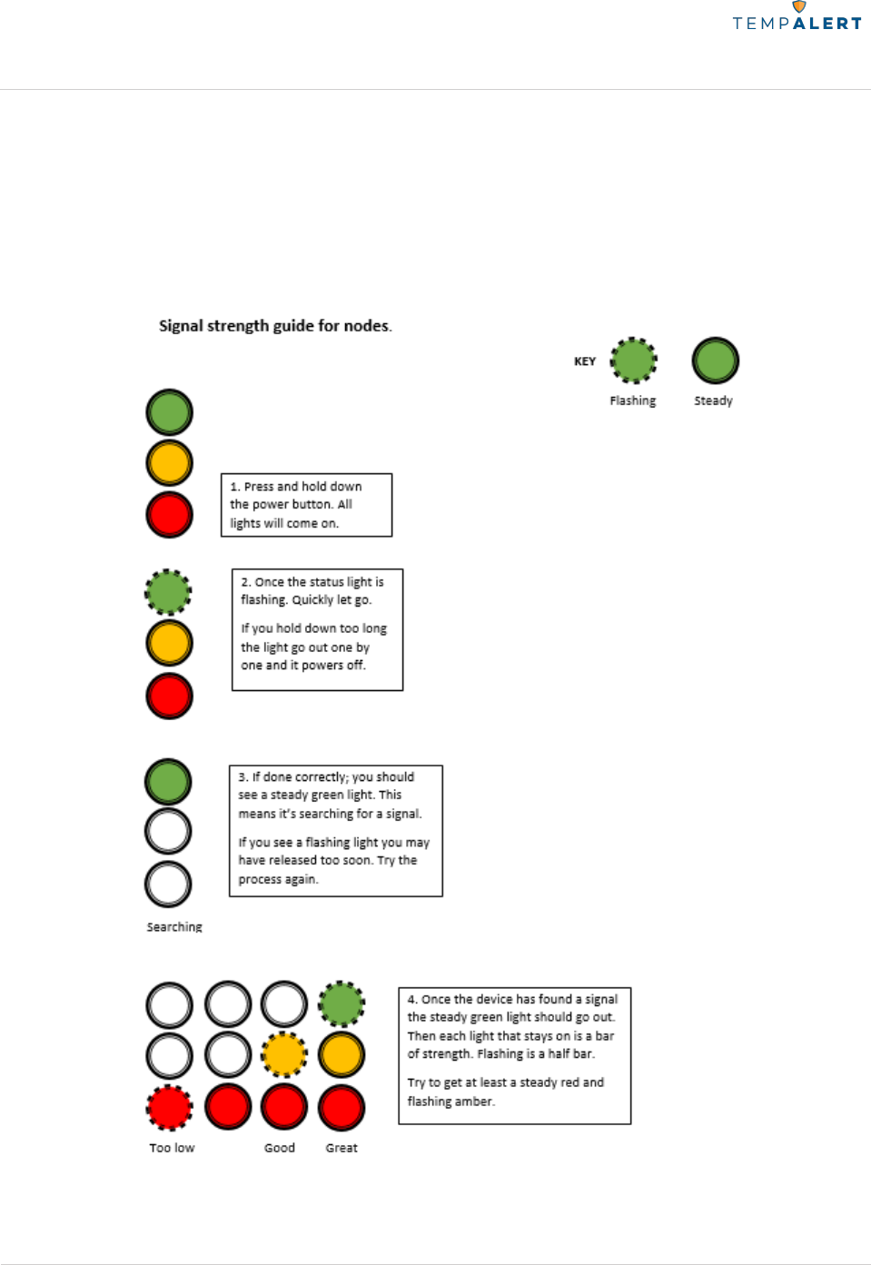
Signal Strength Indicator Mode
This mode is used to discover how strong the signal is between the wireless sensor and the
closest gateway.
To Enter Signal Strength Mode:
TempAlert Ethernet Gateway
User Manual
www.tempalert.com
Tel: (866) 524-3540
Page 18 of 22 TempAlert Ethernet Gateway User Guide v 4.22
186 Lincoln Street, 8th Floor, Boston MA 02111 | p: (866) 524-3540 | f: (866) 415-9884 | www.tempalert.com | info@tempalert.com
LED Indicator Lights
LED
1 Blink
2 Blinks
3 Blinks
Fast Blinking
Status
Last transmission
to the gateway
successful
Last
transmission to
the gateway
successful but
low signal
Attempting to
transmit to the
gateway
Information
No external sensor
Low battery
Failure
Not registered on
Insights™
No signal
Failed to
communicate
with wireless
radio module
Failure light blink/not reporting to cloud
First make sure the Gateway is powered on and communicating. If it is, try bringing the failing
wireless sensor near the Gateway and pressing the power button once to reboot. If it transmits
after a few seconds then you can use signal strength mode to find the ideal placement for it.
All three lights turn on and then off without pressing anything
This light pattern may indicate potential hardware damage, please contact our support team at
support@tempalert.com.
No lights turn on
The battery may have discharged. Try replacing them with two AA batteries.

TempAlert Ethernet Gateway
User Manual
www.tempalert.com
Tel: (866) 524-3540
Page 19 of 22 TempAlert Ethernet Gateway User Guide v 4.22
186 Lincoln Street, 8th Floor, Boston MA 02111 | p: (866) 524-3540 | f: (866) 415-9884 | www.tempalert.com | info@tempalert.com
Important Usage Information
WARNING:
Changes or modifications not expressly approved by TempAlert could void the user’s authority
to operate the equipment.
This device has been designed to operate with the antennas listed below, and having a
maximum gain of -2.53dBi. Antennas not included in this list or having a gain greater than
-2.53dBi are strictly prohibited for use with this device. The required antenna impedance is 50
ohms.”
To reduce potential radio interference to other users, the antenna type and its gain should be
so chosen that the equivalent isotropically radiated power (e.i.r.p.) is not more than that
permitted for successful communication.
This device complies with FCC and IC radiation exposure limits set forth for an uncontrolled
environment. The device should be installed and operated with a minimum distance of 20cm
between the radiator and your body. This device must not be collocated or operating in
conjunction with any other antenna or transmitter.

TempAlert Ethernet Gateway
User Manual
www.tempalert.com
Tel: (866) 524-3540
Page 20 of 22 TempAlert Ethernet Gateway User Guide v 4.22
186 Lincoln Street, 8th Floor, Boston MA 02111 | p: (866) 524-3540 | f: (866) 415-9884 | www.tempalert.com | info@tempalert.com
FCC STATEMENT:
This device complies with Part 15 of the FCC Rules. Operation is subject to the following two
conditions: (1) this device may not cause harmful interference, and (2) this device must accept
any interference received, including interference that may cause undesired operation.
FCC ID: SZ9TMWIFI440Z
This equipment has been tested and found to comply with the limits for a Class B digital
device, pursuant to Part 15 of the FCC Rules. These limits are designed to provide reasonable
protection against harmful interference in a residential installation. This equipment generates,
uses and can radiate radio frequency energy and, if not installed and used in accordance with
the instructions, may cause harmful interference to radio communications. However, there is
no guarantee that interference will not occur in a particular installation. If this equipment does
cause harmful interference to radio or television reception, which can be determined by turning
the equipment off and on, the user is encouraged to try to correct the interference by one of
the following measures:
-- Reorient or relocate the receiving antenna.
-- Increase the separation between the equipment and receiver.
-- Connect the equipment into an outlet on a circuit different from that to which the
receiver is connected.
-- Consult the dealer or an experienced radio/TV technician for help.
This device complies with FCC and IC radiation exposure limits set forth for an uncontrolled
environment. The device should be installed and operated with a minimum distance of 20cm
between the radiator and your body. This device must not be collocated or operating in
conjunction with any other antenna or transmitter.

TempAlert Ethernet Gateway
User Manual
www.tempalert.com
Tel: (866) 524-3540
Page 21 of 22 TempAlert Ethernet Gateway User Guide v 4.22
186 Lincoln Street, 8th Floor, Boston MA 02111 | p: (866) 524-3540 | f: (866) 415-9884 | www.tempalert.com | info@tempalert.com
INDUSTRY CANADA (IC) STATEMENT:
This device complies with Industry Canada licence-exempt RSS standard(s). Operation is
subject to the following two conditions: (1) this device may not cause interference, and (2) this
device must accept any interference, including interference that may cause undesired
operation of the device.
IC: 10940A-TMWIFI440Z
Le présent appareil est conforme aux CNR d'Industrie Canada applicables aux appareils radio
exempts de licence. L'exploitation est autorisée aux deux conditions suivantes : (1) l'appareil ne
doit pas produire de brouillage, et (2) l'appareil doit accepter tout brouillage radioélectrique
subi, même si le brouillage est susceptible d'en compromettre le fonctionnement.
This device has been designed to operate with the antennas listed below, and having a
maximum gain of -2.53dBi. Antennas not included in this list or having a gain greater than
-2.53dBi are strictly prohibited for use with this device. The required antenna impedance is 50
ohms.”
To reduce potential radio interference to other users, the antenna type and its gain should be
so chosen that the equivalent isotropically radiated power (e.i.r.p.) is not more than that
permitted for successful communication.
This device complies with FCC and IC radiation exposure limits set forth for an uncontrolled
environment. The device should be installed and operated with a minimum distance of 20cm
between the radiator and your body. This device must not be collocated or operating in
conjunction with any other antenna or transmitter.
This device is protected by United States Patent Numbers:
7,952,485; 8,547,226; 8,248,252; 8,599,012; 8,779,926; 9,247,322; 9,500,532; and 9,541,454.

TempAlert Ethernet Gateway
User Manual
www.tempalert.com
Tel: (866) 524-3540
Page 22 of 22 TempAlert Ethernet Gateway User Guide v 4.22
186 Lincoln Street, 8th Floor, Boston MA 02111 | p: (866) 524-3540 | f: (866) 415-9884 | www.tempalert.com | info@tempalert.com
Contact Us
For questions or support, please contact support@tempalert.com 24/7 for expedited
technical support service