SmartSight Networks MF24 MF24 User Manual
SmartSight Networks Inc MF24 Users Manual
Contents
- 1. Users Manual
- 2. Revised user manaul
Users Manual

USER’S MANUAL V1.2
(MF24-AV/ADV/AVr/ADVr)
Instructions on how to install, configure
and operate the MultiSite system
(North American Models)
Comlink Group Inc.
1800 Berlier St.
Laval, QC
H7L 4S4
Canada
www.comlinkgroup.com

ii
_____________________________________________________________________________________________
INFORMATION TO USER
This device complies with Part 15 of the FCC Rules. Operation is subject to the following
two conditions: (1) This device may not cause harmful interference, and (2) This device
must accept any interference received, including interference that may cause undesired
operation.
This equipment has been tested and found to comply with the limits for Class B Digital
Device, pursuant to Part 15 of the FCC Rules. These limits are designed to provide
reasonable protection against harmful interference in residential installation. This
equipment generates and can radiate radio frequency energy and, if not installed and used
in accordance with the instructions, may cause harmful interference to radio
communications. However, there is no guarantee that interference will not occur in a
particular installation. If this equipment does cause harmful interference to radio or
television reception, which can be determined by turning the equipment off and on, the
user is encouraged to try to correct the interference by one or more of the following
measures.
• Reorient or relocate the receiving antenna
• Increase the separation between the equipment and receiver
• Connect the equipment into an outlet on a circuit different from that to which the receiver
is connected
• Consult the dealer or an experienced radio/TV technician for help
Any changes or modifications not expressly approved by the party responsible for
compliance could void the user’s authority to operate the equipment.
iii
_____________________________________________________________________________________________
Microflex AV/ADV/AVr/ADVr North-American user’s manual / Rev 1.2
WARRANTY
Each standard product manufactured by ComLink Group is warranted to meet all
published specifications and to be free from defects in material and workmanship for a
period of three (3) years from date of delivery as evidenced by ComLink Group’s packing
slip or other transportation receipt. Products showing damage by misuse, abnormal
conditions of operation or Products which have been modified by Buyer or have been
repaired or altered outside ComLink Group’s factory without a specific authorization from
ComLink Group shall be excluded from this warranty. ComLink Group shall in no event be
responsible for incidental or consequential damages including without limitation, personal
injury or property damage.
ComLink Group’s responsibility under this warranty shall be to repair or replace, at its
option, defective work or parts returned to ComLink Group with transportation charges to
ComLink Group’s factory paid by Buyer and return paid by COMLINK. If COMLINK
determines that the Product is not defective within the terms of the warranty, Buyer shall
pay all costs of handling and transportation. ComLink Group may, at its option, elect to
correct any warranty defects by sending its supervisory or technical representative, at
ComLink Group’s expense, to customer’s plant or location. ComLink Group shall in no
event be responsible for incidental or consequential damages including, without limitation,
personal injury or property damage.
SINCE COMLINK GROUP HAS NO CONTROL OVER CONDITIONS OF USE, NO
WARRANTY IS MADE OR IMPLIED AS TO SUITABILITY FOR CUSTOMER’S
INTENDED USE. THERE ARE NO WARRANTIES, EXPRESSED OR IMPLIED,
EXCEPT AS STATED HEREIN. This limitation on warranties shall not be modified by
verbal representations.
Equipment shipped EX-Works ComLink Group factory shall become the property of Buyer,
upon transfer to the common carrier. Buyer shall communicate directly with the carrier by
immediately requesting carrier’s inspection upon evidence of damage in shipment.
Buyer must obtain a Return Materials Authorization (RMA) number and shipping
instructions from ComLink Group prior to returning any Product under warranty. DO NOT
RETURN ANY COMLINK GROUP PRODUCT TO THE FACTORY UNTIL RMA AND
SHIPPING INSTRUCTIONS ARE RECEIVED.

iv
_____________________________________________________________________________________________
Customer Support
If after reading this manual, you encounter any trouble installing or using any MultiSite
product, please contact your local distributor. If problems are not solved, you can call
ComLink Group’s Customer Service for assistance during normal business hours (EST).
The fax and phone numbers are:
Ph: (450) 686-9000 (888) 494-7337 (North America)
Fax: (450) 686-0198
You may also e-mail your inquiries and comments at the following address:
techsupport@comlinkgroup.com
About this User Manual
This User’s Manual covers the information and procedures on installing, configuring and
using the Microflex MF24-AV/Avr/ADV/ADVr modules. This manual is also a reference for
persons who must perform or coordinate the tasks associated with programming and
managing a Multisite wireless network.
To control the video display and Pan-Tilt-Zoom functions in multipoint, you will need to
read Chapter 5 to learn how to use the Pelco KBD4000
TM
keyboard. If you are using a
point-to-point video link and do not want to take advantage of the 4 camera inputs and
Quad View display of these 4 cameras, you do not require the KBD4000 and therefore do
not need to read this section. You will need, however, to read Chapter 4 to learn how to
program the DATA1 serial port of both video transmitter and receiver for the specific data
rate of the Pan-Tilt-Zoom system you wish to use.
For customers using a RS-485/422 port, you may need to change the port to RS-232
setting if you configuration of the module is required. Please review Appendix E for
converting from RS-485/422 to RS-232 and vice-versa (Appendix G for FV module)
For customers who have ordered a Line Level audio interface and plan to use a leased or
dry line, please refer to Appendix G for interface assistance.
Prerequisite Knowledge
Throughout the user's manual there are explanations and procedures that presume
working familiarity with radios, as well as basic digital data communication concepts and
practices, and an understanding of the concepts underlying telecommunication systems.
If you are not familiar with the concepts and practices involved in these disciplines, we
recommend that you familiarize yourself with them before proceeding.

v
_____________________________________________________________________________________________
Microflex AV/ADV/AVr/ADVr North-American user’s manual / Rev 1.2
Manual Conventions
Suggestion
Note
Warning

vi
_____________________________________________________________________________________________
Table of Content
CHAPTER 1 OVERVIEW ......................................................................................................1
1.1 P
RODUCT
..........................................................................................................................1
1.2 F
EATURES
........................................................................................................................1
1.3 A
PPLICATIONS
..................................................................................................................2
1.4 E
XTERNAL MODULE DESCRIPTION
....................................................................................2
1.5 I
NTERNAL
D
ESCRIPTION
...................................................................................................4
1.6 S
ETTING THE
M
ASTER OR
S
LAVE
M
ODE
..........................................................................8
CHAPTER 2 MICROFLEX INSTALLATION AND OPERATION .................................9
2.1 M
ICROFLEX
S
ETUP
G
UIDE
................................................................................................9
CHAPTER 3 PROPER MICROWAVE NETWORK PLANNING..................................13
3.1 RF P
LANNING
................................................................................................................13
3.1.1 Network Planning.................................................................................................. 13
3.1.2 Evaluating System Gain Requirements ................................................................. 16
3.1.3 Verifying Line of Sight and Fresnel Zone Clearance............................................19
3.1.4 On-Site Testing......................................................................................................20
3.2 C
OPING WITH
I
NTERFERENCE
.........................................................................................22
CHAPTER 4 MNM CONFIGURATION SOFTWARE INTEGRATION.......................24
4.1 I
NSTALLING THE
MNM..................................................................................................24
4.2 U
SING
M
ULTISITE
N
ETWORK
M
ANAGER
(MNM)..........................................................25
4.2.1 Launching the MNM Programmer........................................................................ 25
4.3 M
AIN
O
PERATIONS
.........................................................................................................27
4.3.1 Network List .......................................................................................................... 28
4.3.2 Unit Properties......................................................................................................28
4.3.3 Menu Bar...............................................................................................................28
4.3.4 Tool Bar.................................................................................................................29
4.4 U
NIT
P
ROPERTIES
...........................................................................................................29
4.4.1 General..................................................................................................................29
4.4.2 Audio .....................................................................................................................30
4.4.3 Data.......................................................................................................................32
4.4.4 Radio .....................................................................................................................33
4.4.5 Video......................................................................................................................34
4.5 D
IAGNOSTICS
.................................................................................................................34
4.6 F
IRMWARE
U
PDATE
.......................................................................................................35
4.7 M
ISCELLANEOUS
............................................................................................................36
4.7.1 Factory Reset (same as hardware switch SW1; see chapter 1) ............................36
4.7.2 Unit Reset (same as hardware switch SW2; see chapter 1)..................................36
CHAPTER 5 USING THE KBD4000 IN A MULTISITE NETWORK............................37
5.1 C
ONFIGURING THE
KBD4000TM .................................................................................... 38
5.2 C
ONFIGURING THE
M
ICROFLEX
V
IDEO
R
ECEIVER
..........................................................38
5.3 C
ONNECTING THE
KBD4000TM
TO THE
M
ICROFLEX VIDEO RECEIVER
..........................39
5.4 C
ONNECTING THE
KBD4000TM
TO MULTIPLE
M
ICROFLEX RECEIVERS
..........................39
5.5 U
SING THE
KBD4000TM
IN A
M
ICROFLEX
V
IDEO
N
ETWORK
.........................................41
vii
_____________________________________________________________________________________________
Microflex AV/ADV/AVr/ADVr North-American user’s manual / Rev 1.2
5.5.1 Microflex ID’s ....................................................................................................... 41
5.5.2 Camera selection in Full Screen Display..............................................................41
5.5.3 Multiple Camera display.......................................................................................42
5.5.4 Menus ....................................................................................................................42
5.6 P
AN
,
TILT AND ZOOM FUNCTIONALITY
...........................................................................44
5.7 P
ASSWORD
.....................................................................................................................45
5.8 U
SING ONE
KBD4000TM
AND MULTIPLE VIDEO RECEIVERS
. ..........................................45
5.9 KBD4000TM
KEYBOARD DEFINITIONS
...........................................................................46
F
IGURE
1- M
ICROFLEX
AV
R
/ADV
R
– E
XTERNAL VIEW
..................................................................2
F
IGURE
2- M
ICROFLEX
AV/ADV – E
XTERNAL VIEW
......................................................................3
F
IGURE
3 - M
ICROFLEX
– I
NTERNAL DESCRIPTION
...........................................................................4
F
IGURE
4 - M
ASTER AND
S
LAVE MODE SELECTION
..........................................................................8
F
IGURE
5 – M
ICROFLEX
ADV/ADV
R CABLING
.............................................................................11
F
IGURE
6 - B
ASIC
M
ULTIPOINT
C
ELL
.............................................................................................14
F
IGURE
7 - M
ULTIPOINT
N
ETWORK WITH
R
EPEATER
.....................................................................14
F
IGURE
8 - M
ULTIPOINT
N
ETWORK WITH
T
WO
R
EPEATERS
...........................................................15
F
IGURE
9 - D
IFFERENCE
B
ETWEEN
F
RESNEL
Z
ONE AND
V
ISUAL
L
INE OF
S
IGHT
...........................19
F
IGURE
10 – R
UN
D
IALOG
B
OX
.....................................................................................................24
F
IGURE
11 – W
ELCOME
S
ETUP
D
IALOG
B
OX
.................................................................................24
F
IGURE
12 – S
ETUP
C
OMPLETE
D
IALOG
B
OX
................................................................................25
F
IGURE
13 – MNM M
AIN VIEW
.....................................................................................................26
F
IGURE
14 – C
OMMUNICATION
C
ONFIGURATION
D
IALOG
B
OX
.....................................................26
F
IGURE
15 – MNM M
AIN VIEW SECTIONS
.....................................................................................27
F
IGURE
16 – MNM T
OOL
B
AR
......................................................................................................29
F
IGURE
17 – D
IAGNOSTIC WINDOW
................................................................................................35
F
IGURE
18 – D
IAGNOSTIC WINDOW
................................................................................................36
F
IGURE
19 - S
TRETCH TO ELONGATE SEALANT TAPE WHILE WRAPPING OVER CONNECTION
...........51
F
IGURE
20 - S
TRETCH TO ELONGATE ELECTRICAL TAPE WHILE WRAPPING OVER SEALANT TAPE
...51
F
IGURE
21 - E
LECTRICAL TAPE WRAPPED TIGHTLY AGAINST CABLE JACKET
,
TYPICAL BOTH ENDS
52
T
ABLE
1 – A
NTENNA
G
AIN
............................................................................................................16
T
ABLE
2 – W
EATHER DEPENDENT RATINGS
...................................................................................17
T
ABLE
3 – D
ISTANCE
V
S
P
ATH
L
OSS
.............................................................................................18
T
ABLE
4 –
0.6F1 V
ALUES AT
V
ARIOUS
D
ISTANCES
.......................................................................20
1
_____________________________________________________________________________________________
Microflex AV/ADV/AVr/ADVr North-American user’s manual / Rev 1.2
CHAPTER 1 Overview
1.1 Product
The Microflex is your solution for reliable and cost-effective point-to-point or
multipoint wireless video communications. This module supports video and data
and/or telephony applications.
Capabilities of the Microflex are:
• All digital multipoint networking using Demand Assigned
TDMA/TDD access
• Supports up to 16 remote video, voice and data terminals
• Protocol transparent point-to-multipoint polled data port
• Support of multiple point-to-point data ports (up to 16)
• User-friendly PC/WindowsTM based system programming and
Multisite Network Management (MNM)
1.2 Features
Microflex provides the following features:
• Up to four (4) video cameras per transceiver modules
• One or two integrated analog telephone line interface (subscriber
or telco interface) and/or line level audio
• One or two asynchronous data ports (RS-232 or RS-485 levels)
• Reliable polled data communications using error detection and
correction algorithms
• Capability to operate in PBX or DOD (direct outward dial) voice
mode
2
_____________________________________________________________________________________________
1.3 Applications
The Microflex is capable of operating in a point-to-point as well as a point-to-
multipoint environment.
In a typical point-to-multipoint configuration, one Microflex must be set in master
mode to act as a network controller (typically installed at the base). It communicates
with several remote Microflex (up to 16) set in slave mode, on a single microwave
frequency. If a single remote Microflex is used, the system becomes a point-to-point
link.
___________________________________________________________________
Chapter 4 provides a comprehensive description of the MNM configuration software. The
Microflex is typically shipped with its factory default configuration unless indicated
otherwise on the configuration sheet attached. The MNM software may have to be used
to configure each Microflex for the required application.
___________________________________________________________________
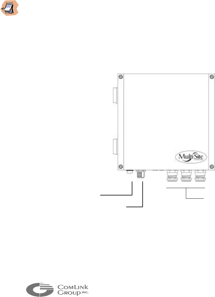
1.4 External module description
Figure 1- Microflex AVr/ADVr – External view
Aluminum cable gland
connectors (for video,
power/audio/data cable entry)
Status indicator
RF connector
(N type female)
3
_____________________________________________________________________________________________
Microflex AV/ADV/AVr/ADVr North-American user’s manual / Rev 1.2
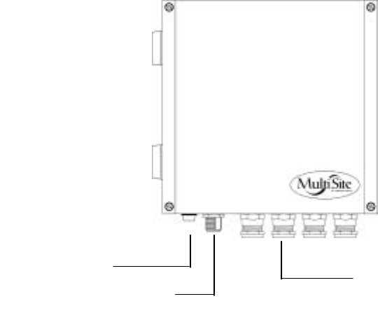
Figure 2- Microflex AV/ADV – External view
The Microflex electronics is enclosed in a weather-tight cast aluminum module. All
cable entries and the indicator are mounted on the underside of the module to
maintain its weather-tight properties. The underside of the Microflex integrates one
(1) visual indicator with the following function:
• STATUS - Bi-color indicator (Green or Red)
This indicator illuminates Green when the module is operating normally and has
not detected an internal fault. It will turn Red at power up if the module detects
an internal fault. It will flash Green during radio firmware update (see chapter 4;
configuring the network with the MNM software). Steady off at power up also
indicates an internal failure.
Aluminum cable gland
connectors (for video,
power/audio/data cable entry)
Status indicator
RF connector
(N type female)
4
_____________________________________________________________________________________________
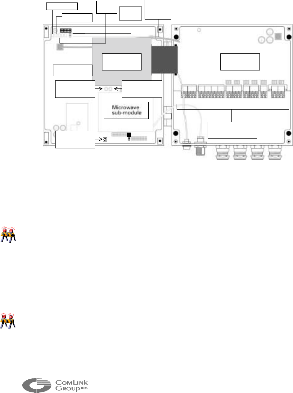
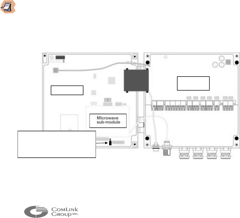
1.5 Internal Description
Figure 3 - Microflex – Internal description
All connections to the Microflex including power, video, data and audio cabling are
made via pluggable industrial terminals. The signal description for each terminal is
indicated on a cabling label inside the enclosure.
____________________________________________________________________________
Care must be taken not to mix a Microflex FXS interface and FXO interface when
connecting the audio signals. Connecting a telephone line (FXO) instead of telephone
set can damage the FXS sub-module. A label at the back of the enclosure indicates the
audio option selected (O for FXO, S for FXS and L for line level).
____________________________________________________________________________
The industrial terminals are mounted on an interconnection board. This removable
board integrates a two stage surge/lightning protection circuit providing industrial
type protection for the main electronics.
____________________________________________________________________________
Each surge or lightning strike weakens the protection circuitry. It is recommended in
lightning prone geographical areas and as part of a maintenance program, to replace the
protection board every 2 years. Please contact ComLink factory for part number and
ordering procedure.
____________________________________________________________________________
The interconnection board connects to the main Microflex board via a pluggable
ribbon type cable assembly. If this ribbon needs to be disconnected for
Main Board
Protection
Board
Status (DS1)
Power (DS2)
Comms
(DS3) Phone
line (D1)
Carrier
Detect-
CD
(
D2
)
Interconnection
b
locks
Reset Switch 2
(
SW2
)
Reset Switch 1
(
SW1
)
Reset Switch 3
(
SW3
)
Video Codec
Board
5
_____________________________________________________________________________________________
Microflex AV/ADV/AVr/ADVr North-American user’s manual / Rev 1.2
maintenance, do not pull the ribbon as this may damage the cable assembly. Grab
the connector on the main PCB side and pull carefully.
The main board integrates five (5) visual indicators for troubleshooting as well as an
RF signal strength (RSSI) bargraph indicator to align the antenna and determine the
signal margin available:
• STATUS (DS1) - Bi-color indicator (Green or Red)
This indicator is equivalent to the external STATUS LED indicator. It illuminates
Green when the module has not detected an internal fault and is operating
normally. It will turn Red at power up if the module detects an internal fault. It
will flash Green during radio firmware update (see chapter 4; configuring the
network with the MNM software).
• POWER (DS2) - Bi-color indicator (Green or Red)
This indicator illuminates Green when there is at least +10VDC supplied to the
interconnect board and the power supply used has an appropriate capacity
(typically 1A @ 15 VDC). It will illuminate Red if power is below +10 VDC, if
capacity is insufficient or if there is an internal problem creating excessive power
consumption.
• COMMS (DS3) - Bi-color indicator (Green or Red)
This indicator flashes Red during power-up if the radio module is not properly
detected. Following power-up the LED behavior will depend on the module
configuration:
(a) Master Mode Configuration:
It will flash Green at a rate of 2 flashes per second following powering-up
sequence. It will remain in this state if it is able to communicate with a remote
Microflex set in Slave Mode. If it cannot communicate with a slave Microflex, it
will flash Red at a rate of 2 flashes per second. It will flash Green at a rate of 8
flashes per second when there is voice or data activity between the module and
another Microflex or when the remote slave Microflex identifies itself (once every
30 seconds).
(b) Slave Mode Configuration:
If it is not capable of communicating with a master Microflex It will remain off
following powering-up sequence. It will flash Green at a rate of 2 flashes per
second if it is able to communicate with a master Microflex. It will flash Green at
a rate of 8 flashes per second when there is voice or data activity between the
module and a master Microflex or every time it transmits its ID to the master
Microflex (once every 30 seconds on average but at random times).
_

6
_____________________________________________________________________________________________
__________________ ________________________________________________________
If the three (3) LEDs, power, Status and Comms are steady green simultaneously, the
Microflex is in its ‘’loader mode’’. Proper firmware has to be downloaded in the Microflex
for the module to be operational. Such download cannot be done over the RF network, it
must be performed locally (see chapter 4 for further details)
___________________________________________________________________
• PHONE/LINE (D1) – Green indicator
This indicator flashes 8 times per second in synch with the ring signal. The
indicator illuminates steady when a telephone call is in progress.
• CD (D2) - Green indicator
This is the RF carrier detect indicator. The LED behavior will depend on the
module configuration:
(a) Master Mode Configuration:
It will flash Green with varying intensity when activity is occurring in the network
(data or voice communications). The more the network is loaded, the more
intense the LED will glow. If there is no activity and the remote Microflex
modules can identify themselves to the master module, the LED will be on
momentarily every time it receives an ID packet (once every 30 seconds).
(b) Slave Mode Configuration:
It will flash green at a rate of at least 20 times per second (almost steady green)
when receiving a valid signal from the master module.
____________________________________________________________________________
The CD LED will not flash green if submitted to interference from nearby transmitters
operating in the same RF band. Such interference may however cause the LED to flash
intermittently by corrupting valid data packets received from another Microflex. The LED
may also flash intermittently if the signal received is at the limit of the receiver
sensitivity. The RSSI level can be used to differentiate between the two (2) conditions.
___________________________________________________________________
• RSSI (DS7 to DS16) - Green indicators
A ten (10) LED indicator bar graph is used to provide received signal strength
(RSSI). The RSSI indicators illuminate Green. RSSI values are not factory
calibrated and can have an error of +/- 4 dB as compared to true RSSI.
7
_____________________________________________________________________________________________
Microflex AV/ADV/AVr/ADVr North-American user’s manual / Rev 1.2
The minimum signal level at which the Microflex can operate depends on the data
rate setting. At high bit rate (558 kbps), the Microflex offers a -96 dBm receiver
sensitivity (@10-5 BER). By decreasing to medium bit rate (384 kbps), the
sensitivity increases to –98 dBm and at low bit rate (192 kbps), to -101 dBm.
____________________________________________________________________________
The bit rate should always be set to the minimum required to obtain the most robustness
to interference and the best receive sensitivity. The bit rate required depends on the
system load and the nature of the data transmitted. For most video applications the
medium data rate setting is a good compromise between link robustness and video quality.
For mixed data, audio, and video applications, the radio data rate used will depend on the
number of remote stations used. It is recommended to use medium rate for mixed signals
applications.
____________________________________________________________________________
The Microflex main electronics board integrates 3 switches offering the following
functions:
• RESET SWITCH 1 (SW1) – Reset to factory default
A reset-to-factory-default switch (SW1) can be triggered if the Microflex fails to
respond. This may be useful following the download of a corrupted or invalid
program or improperly programming the module using the MNM software (see
chapter 4). The switch must be held for at least 5 seconds while the power is ON
for a reset to be valid. Following a reset, the Microflex will need to be
programmed for proper operation in the network (see Appendix A for default
factory values).
Microflex RSSI
INDICATOR LED RSSI (dBm)
Indicator DS16 (min) -101 +/- 4 dB
Indicator DS15 -98 +/- 4 dB
Indicator DS14 -95 +/- 4 dB
Indicator DS13 -92 +/- 4 dB
Indicator DS12 -89 +/- 4 dB
Indicator DS11 -83 +/- 4 dB
Indicator DS10 -77 +/- 4 dB
Indicator DS9 -71 +/- 4 dB
Indicator DS8 -65 +/- 4 dB
Indicator DS7 (max) -59 +/- 4 dB
8
_____________________________________________________________________________________________
• RESET SWITCH 2 (SW2) – Hardware reset
A hardware reset can be made by momentarily pressing the SW2 switch. This
can be useful if the module appears not to be responding properly.
• RESET SWITCH 3 (SW3) – radio loader software
RESERVED
1.6 Setting the Master or Slave Mode
The Microflex main electronic board integrates a two (2) position jumper to set the
module for Master or Slave mode operation. Refer to the illustration below for
proper position in both modes.
____________________________________________________________________________
A Multisite network must have a single Master module. If one Microflex is set in Master
mode, all other modules should be set in Slave mode. The Master module should ideally be
installed in an accessible location, typically at the base station. The only exception to this
is for a point-to-point video link. In point-to-point, it is best to set the MF24-ADV in
Master Mode and the MF24-ADVr is Slave Mode. This allows a higher video data
throughput (300 kbps sustained) and slightly higher quality.
___________________________________________________________________
Figure 4 - Master and Slave mode selection
Main Board
Protection
Board
Jumper setting (master mode); Set
j
umper on two (2) upper pins for
slave mode and two (2) lower
p
ins for master mode

9
_____________________________________________________________________________________________
Microflex AV/ADV/AVr/ADVr North-American user’s manual / Rev 1.2
CHAPTER 2 Microflex installation and operation
Your Microflex shipment should contain the following items:
• Microflex module with requested options
• Pole mounting bracket with two (2) stainless steel collars (for
0.75-2 inch poles unless an optional mount has been ordered)
• 15 VDC external power supply (Optional)
• Antenna (Optional)
• Microflex configuration sheet
• User’s manual (one set per system ordered)
• MNM based configuration diskettes (one set per system ordered)
___________________________________________________________________
Check the material against the packing list to make sure you have received everything. If
something is missing or if you discover shipping damage, please contact your distributor.
___________________________________________________________________
2.1 Microflex Setup Guide
Use the guidelines in the following subsection to assist you in cabling and installing
the Microflex.
STEP 1 Installing the Microflex module
The Microflex is shipped with a mounting bracket. This bracket is supplied with a
special water-sealing gel backing. This backing must not be removed in order to
maintain the enclosure weather-tight feature. Three (3) stainless steel screws are
also supplied to install the bracket on the back of the Microflex enclosure. Mount
the bracket to the back of the enclosure and align the screws with the mounting
holes. Tighten the three (3) screws firmly while being careful not to strip the
aluminum threads. Some gel may flow out from under the bracket while tightening.
This extra gel can be removed with water and mild soap or an alcoholic solution.
Using the mounting bracket and collars supplied, the Microflex can be mounted on
any pole with a 18-50 mm (0.75-2.0 inch) diameter. ComLink also supplies
mounting brackets for mounting on walls and larger collar size for mounting on light
poles or other large diameter poles. Contact ComLink factory if you require a
different mounting option than the one supplied.

10
_____________________________________________________________________________________________
STEP 2 Installing the antenna
The Microflex is designed for outdoor installation, next to the antenna. Such
installation minimizes cable losses thereby maximizing link margin. Install the
Microflex module with its antenna on an appropriate mast or tower. Depending on
whether the antenna has a pigtail or not, you may need to install a coaxial cable
jumper (with N connectors) between the Microflex and antenna. The coaxial cable
recommended is an RG-142 double shield (or equivalent) with a maximum length of
3 meters to reduce cable loss (use quality type N clamp connectors to ensure a
watertight setup).
____________________________________________________________________________
Install the Microflex module at the same elevation as the antenna for best lightning
protection. If the Microflex module is installed several meters lower than the antenna, a
2.4 GHz lightning arrester should be used.
Never exceed antenna gains of 11 dBi. The only exception is when
you have significant cable losses. For each dB of cable loss, you can
add 1dB of antenna gain
.
___________________________________________________________________
___________________________________________________________________
Always install the antenna away from wires, power lines and trees for optimum safety and
performance. For more information on antenna installation, refer to the manufacturer’s
documentation included with the antenna.
___________________________________________________________________
STEP 3 Connecting power, audio and data
Connect the power (12-15 VDC recommended), video, audio and data ports
according to the label at the bottom of the Microflex enclosure (see illustration on
next page). The video signal should be carried on RG-59 coaxial cable.
The power and audio signals can be carried using the same cable. This cable
should contain 4 to 5 pairs with an overall shield and have an AWG of 20 (0.81
mm diameter) or larger for optimum performance. Use 2 pairs for the audio and 2-3
pairs to carry power (this will reduce voltage drop between the power supply and the
Microflex).
The data should be carried using a low capacitance non twisted pair
communications cable with an overall shield. A 24 gauge (0.51 mm diameter) low
capacitance conductor will support long cable runs (50-80 meters) for RS-232
signals. The two (2) data ports can use a single multi-conductors cable.
11
_____________________________________________________________________________________________
Microflex AV/ADV/AVr/ADVr North-American user’s manual / Rev 1.2
____________________________________________________________________________
If you are planning to install a long cable extension between the Microflex and the
cameras, PLC/computer equipment and/or the phone equipment, it is highly
recommended to protect these equipments from lightning and power transients (the
Microflex is well protected and does not require additional protection). Several
manufacturers provide protection equipment for video, phone and data ports. ComLink
can provide a list of recommended equipment on request.
____________________________________________________________________________
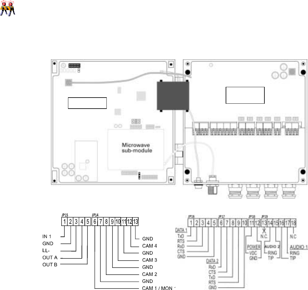
Figure 5 – Microflex ADV/ADVr cabling
STEP 4 Connecting the Microflex for programming
The Microflex Data1 port (JP16) is used for both data applications and module
Main Board
Protection
Board
JP 16 JP 17
JP18
JP 19
JP 14JP 15

12
_____________________________________________________________________________________________
programming. Both Data1 port and Data2 port are configured as DCE interfaces.
They must be connected to a DTE interface for proper operation.
Connect the RS-232 TX, RX and GND signals (RTS/CTS not required) to the
available COM port of your PC running the MNM software. The MNM software will
automatically convert the Microflex Data port 1 to terminal mode (configuration
mode) when started. The Microflex converts its Data port 1 back to its data
application mode following 30 seconds of inactivity from MNM on Data port 1.
___________________________________________________________________
In point-multipoint applcations, DATA 1 is used to transfer PTZ commands. If you have
ordered an RS-485 interface, DATA 1 is configured for RS-485 signal levels. You will not
be able to communicate with the module using a computer and MNM software in such case.
A RS-485 to RS-232 signal converter plug must be used to communicate between the
Microflex and the computer. Such item is not expensive and available from most
telecommunication equipment distributor.
___________________________________________________________________
STEP 5 Verifying the indicators for proper operation
Upon power up, the indicator STATUS indicator on the outside of the enclosure
should turn STEADY GREEN. Review Chapter 1 to understand how the indicators
on the Microflex main board should behave under normal conditions.
____________________________________________________________________________
If the POWER or STATUS indicator turns red momentarily (2 seconds or more) or stays
off at power up, there is a problem with the Microflex or the power supply. Please
contact ComLink technical support team for assistance.
____________________________________________________________________________
STEP 6 Completing the Installation
You have now completed the Microflex initial installation. Once the Microflex is
properly installed it will need to be configured. Please review Chapter 5 ‘’Using the
MNM Software’’ to complete this final step.
13
_____________________________________________________________________________________________
Microflex AV/ADV/AVr/ADVr North-American user’s manual / Rev 1.2
CHAPTER 3 Proper microwave network planning
The Microflex microwave sub-module provides a standard air interface for all Multisite
products. It offers a robust and highly reliable spread spectrum wireless link which can
span 50 kilometers with appropriate installation.
For best operation the network must be properly planned and the antennas must be
installed in such way as to obtain line-of-sight links. This chapter provides a
comprehensive review of network planning and propagation principles.
3.1 RF Planning
Successful operation of a Multisite network lies on the proper installation of the
wireless interface. Such installation requires five (5) phases:
1. Completing the initial network layout
2. Evaluating the system gain required for each link and selecting the
appropriate antennas to use
3. Verifying the line of sight and Fresnel zone clearance for each link within the
network
4. Carrying out an on-site survey (optional)
5. Completing the final system commissioning.
This section presents a step-by-step approach to completing the phases outlined
above.
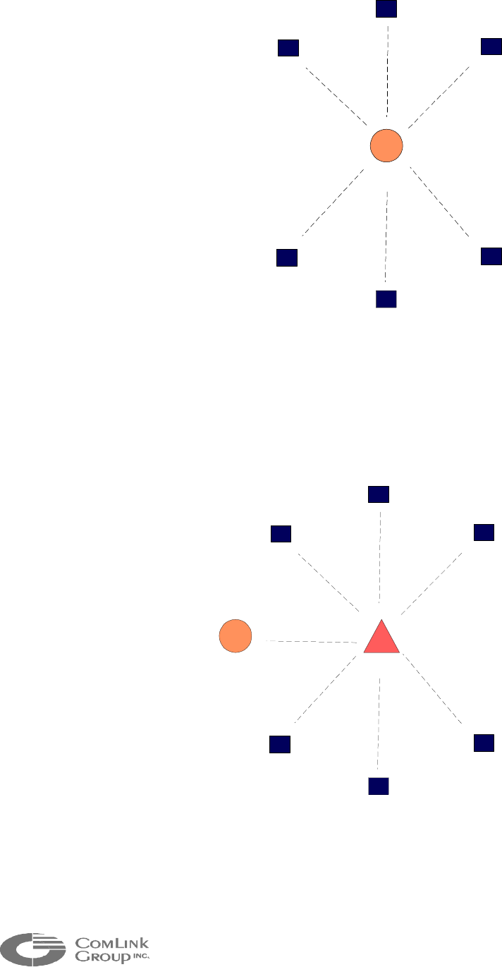
3.1.1 Network Planning
A Multisite network can be configured in multiple ways.
Figure 6, Figure 7 and Figure 8 present some common configurations. The first
step is to establish a network plan based on initial area topology and distances
between each remote station and base.
14
_____________________________________________________________________________________________
RS1
RS2
RS3
RS4
RS5
RS6
BASE
RS : Remote Station
Figure 6 - Basic Multipoint Cell
RS1
RS2
RS3
RS4
RS5
RS6
BASE
Repeater
Figure 7 - Multipoint Network with Repeater
15
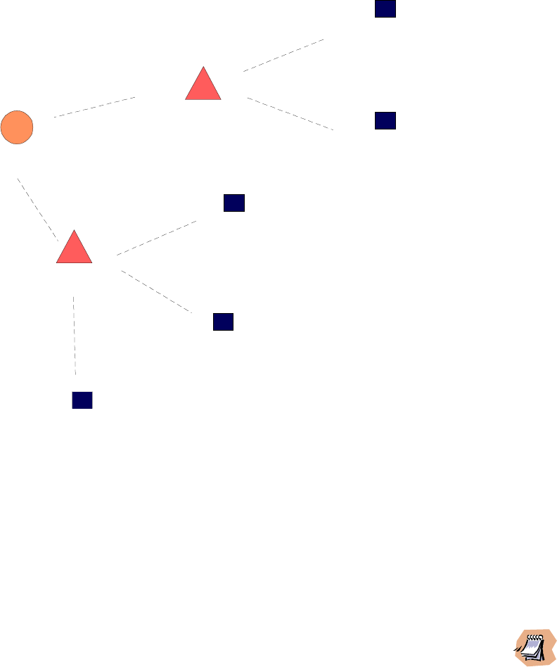
_____________________________________________________________________________________________
Microflex AV/ADV/AVr/ADVr North-American user’s manual / Rev 1.2
RS1
RS2
RS3
RS4
RS5
BASE
Repeater 2
Repeater 1
Figure 8 - Multipoint Network with Two Repeaters
In situations where there are no repeaters, the antenna installed at the base
station should be elevated as high as possible to provide a clear line-of-sight with
all remote stations.
___________________________________________________________________
To establish wireless links exceeding 10 kilometers, it may be necessary to install a
telecommunication tower at the base (if none are available). A more cost-effective
solution could also be to install a repeater on an existing telecommunication tower in the
vicinity of the base.
___________________________________________________________________
To install several repeaters in the system, an adequate mast or tower height must
be planned for each repeater supporting multiple links.
16
_____________________________________________________________________________________________
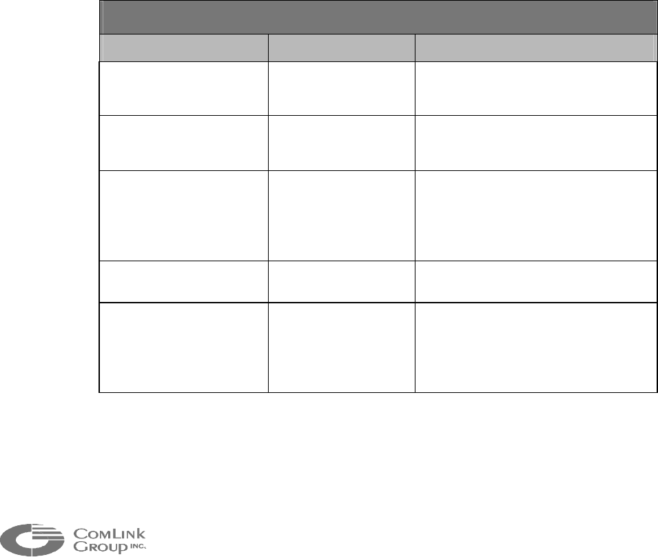
3.1.2 Evaluating System Gain Requirements
To establish a link between two antennas, the following requirements must be
met:
Path loss < system gain (radio gain + antenna gain - cable losses).
The radio gain, at a specific bit error rate (BER), is equal to the transmission
power less the radio receiving sensitivity. The radio gain provided by the
Microflex depends on the power output and data rate selected via the MNM
software. At maximum power and medium data rate (384 kbps), the radio gain is
122 dB. At minimum data rate (192 kbps), the radio gain is 125 dB.
The antenna gain will vary according to the model selected. ComLink offers a
selection of antennas to meet the propagation specifications of various
configurations (See Table 1).
Using the maximum radio gain with the maximum allowed 11 dBi antenna gain
(including cable losses) at both ends, the achievable system gain is 147dB (at
192kbps data rate).
2.4 - 2.4835 GHz
ANTENNA TYPE PART NUMBER DESCRIPTION
6 dBi omni ANT-WO6-24 Antenna used at the base or
repeater station to transmit 360
o
in a
horizontal plane.
8 dBi flat panel
(circular polarized)
ANT-WP8-24 Low profile directional antenna used
at the remote stations.
9 dBi omni ANT-WO9-24 Antenna used at the base or
repeater station to transmit 360
o
in a
horizontal plane (used to
compensate for cable losses of
1dB or more)
11 dBi flat panel ANT-WP11-24 Directional antenna used at the
remote stations.
12 dBi omni ANT-WO12-24 Antenna used at the base or
repeater station to transmit 360
o
in a
horizontal plane (used to
compensate for cable losses 4dB
or more)
Table 1 – Antenna Gain
Since the Microflex can be installed next to the antenna, it is easy to minimize
coaxial cable losses. This allows the use of smaller, lower cost antennas.

17
_____________________________________________________________________________________________
Microflex AV/ADV/AVr/ADVr North-American user’s manual / Rev 1.2
The path loss must always be lower than the system gain. The difference
between the two is the path safety margin. This margin ensures the link to be
functional despite changes in system gain due to heavy rain, temperature
variations, antenna misalignment and overall electrical and mechanical system
aging. The changes due to rain and temperature variations are presented in
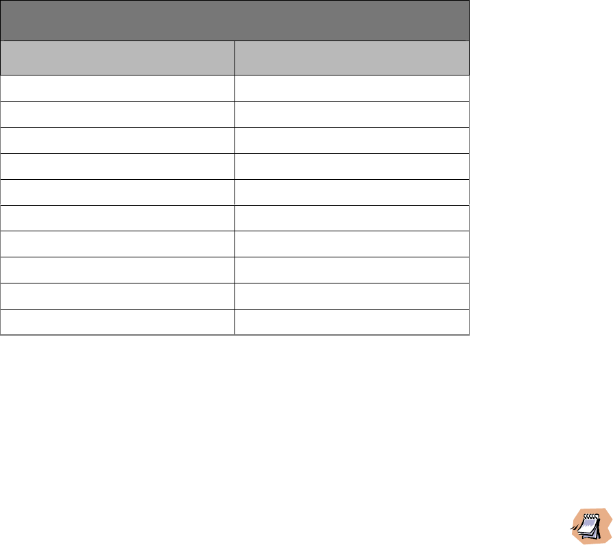
Table 2.
Impact of rain and temperature on Microflex
Condition Reduction in system gain
Rain Up to 0.5 dB/10 km
T = - 40o C Up to 1.0 dB
T = + 55o C Up to 2.5 dB
Table 2 – Weather dependent ratings
Antenna misalignment does not contribute much to path loss in Multisite networks
because most communications take place between an omni antenna (base or
repeater) and a directional antenna (remote station). Aligning such antenna
combination is not as critical when compared to the alignment of two directional
antennas.
A good rule of thumb in a Multisite network is to use a 15-20 dB security margin
to take into account the above factors in addition to multipath fading.
The difficult part in planning a solid link is to evaluate the path loss. There are
many factors that affect the overall losses. Two of these important factors
include topology of the path and in-band and out-of-band interference. Short of
conducting an actual on-site survey, these factors could be hard to assess. A
good starting point is to establish the free space path loss for the link. Free
space path loss is the predominant contributor to the total path loss of a line-of-
sight radio link.
To establish the free space path loss, ComLink has prepared a reference in
Table 3 combining free space path loss at 2.4 GHz to a security margin of 15 dB
and 20 dB. The security margins selected are based on field experience. They
are not calculated from scientific equations and should only be used as a general
guideline.

18
_____________________________________________________________________________________________
Distance
(kilometers) Path loss
@ 2.45 GHz (dB)
15 dB* 20 dB*
5 129 134
10 135 140
12 137 142
15 139 144
20 - 146
Table 3 – Distance Vs Path Loss
As mentioned earlier, maximum system gain is 147 dB. This is achievable at a
data rate of 192kbps using the maximum allowed 11 dBi antenna gain (including
cable losses) at both ends.
The example below illustrate how to calculate the required system gain based on
the path loss provided in Table 3.
Example: A link at 2.45 GHz must be established between a base and a
remote station 10 kilometers apart. Select the appropriate antennas for the link.
a) Path loss = 135 dB (from Table 3)
b) Required radio system gain = path loss = 135 dB.
c) Assuming the system is operating at maximum power and medium bit
rate:
(i) Radio gain = +24 − (−98) = 122 dB
(ii) Total antenna gain = Path loss − Radio gain
= 135 − 122
= 13 dB
For point-to-point operation between two (2) Microflex modules, two (2) 8 dBi flat
panel antennas could be used.
For multipoint networking, an omni antenna must be installed at the base. A 6 dBi
omni could be used at the base with an 8 dBi flat panel antenna at the remote
station.
*
Additional link margin
19
_____________________________________________________________________________________________
Microflex AV/ADV/AVr/ADVr North-American user’s manual / Rev 1.2
___________________________________________________________________
At 2.4 GHz, radio waves are highly attenuated by dense foliage. A link established in the
fall or winter season may be affected adversely in the spring and summertime, if it is
established below tree level.
___________________________________________________________________
Once the network RF gain plan has been empirically calculated, the minimum
antenna elevation at each site to minimize path loss should be established. The
Fresnel zone clearance, the earth’s curvature (can be ignored for links shorter
than 12 kilometers) and any physical obstructions along the path have to be
considered.
3.1.3 Verifying Line of Sight and Fresnel Zone Clearance
Unless it is a very short link distance (typically less than 1-2 kilometers) the path
between the two antennas must be free of obstacles that could disturb
propagation. Such path is called a line of sight path. If there are obstacles, radio
waves will be in part absorbed and in part diffracted by the obstacles (multi-path
fading). Even if operating in such circumstances, links could be established.
However, results are highly unpredictable.
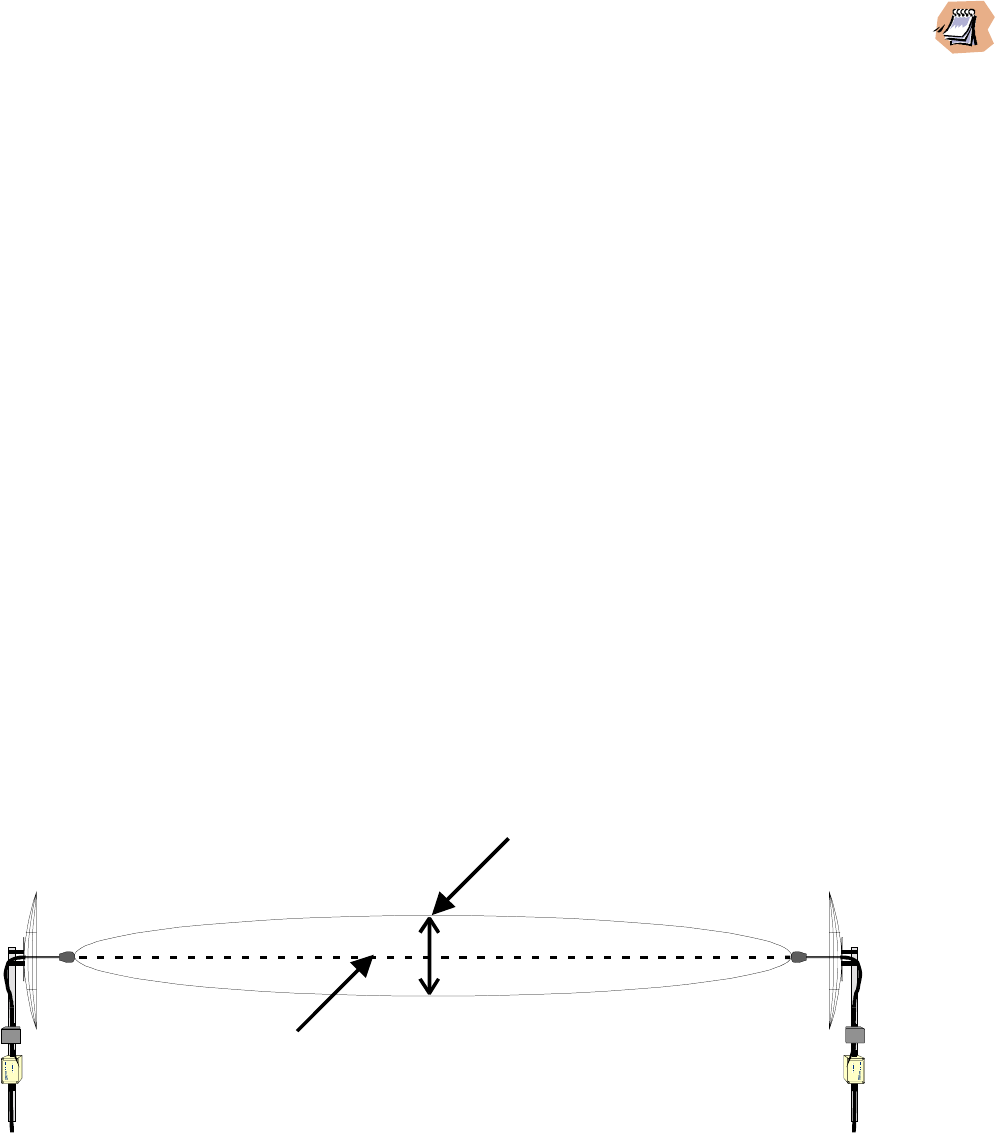
The first requirement of a successful link is therefore a clear line of sight path.
There is a second requirement related to the beam-width of a radio signal. The
beam-width of a radio signal transmitted between two antennas is an elliptical
area immediately surrounding the visual path (see Figure 9). It varies in
thickness depending on the length of the signal path and the frequency of the
signal. The region outlined by this beam-width is known as the first Fresnel zone.
VISUAL LINE OF SIGHT
FIRST FRESNEL
ZONE (F1)
Figure 9 - Difference Between Fresnel Zone and Visual Line of Sight

20
_____________________________________________________________________________________________
The Fresnel zone is always thicker at the mid-point between the two antennas.
Therefore a path that appears to be a perfect line of sight path between the base
and a remote station may not be adequate for a radio signal.
In practice, it has been determined that a radio path can be considered a line of
sight path if it has a clear opening through 60% of the first Fresnel zone (0.6 F1).
Table 4 presents the value of 0.6 F1 for various signal path distances.
DISTANCE
(Km) 0.6F1@ 2.45 GHz
(meters)
5 14
10 20
20 30
30 36
40 41
50 47
60 52
Table 4 – 0.6F1 Values at Various Distances
A common problem encountered in the field and related to the 0.6F1 clearance
rule is a mountain obstruction. The proposed visual path may just barely clear a
mountain but the “radio line of sight” won’t. In such case, the signal will be
partially absorbed and diffracted. Increasing the height of one antenna (or both) is
the only alternative to reduce path loss.
3.1.4 On-Site Testing
Before finalizing the system commissioning, verify the quality of each link
especially if large distances are covered (> 10 kilometers). If in-band interference
is suspected, taking a spectrum analyzer on site to scan the frequency band is
recommended.
To complete a site survey, first install the Microflex configured as a Master at the
base station and power it up. If a repeater station is planned in the system, the
Microflex can temporarily be installed at the repeater site to verify the quality of
the repeater-to-remote station links.

21
_____________________________________________________________________________________________
Microflex AV/ADV/AVr/ADVr North-American user’s manual / Rev 1.2
The Microflex in master mode continuously transmits a beacon (at 10 msec
intervals) to remote stations and this, whether or not, the data or audio port is
active. This beacon provides a good signal for RSSI measurement at each
remote station.
To conduct the remote site survey proceed as follows:
STEP 1.
Install the proper antenna at the remote location proposed
STEP 2.
Connect the Microflex configured as a Slave to the antenna
STEP 3.
Align the antenna to obtain maximum RSSI
STEP 4.
Note the RSSI value
____________________________________________________________________________
If the RSSI bargraph does not reach the third LED indicator at low bit rate and the fourth
indicator at medium bit rate, there might be insufficient margin to guarantee a
continuous high quality link (BER > 10
-5
). Considerable temperature variations and heavy
rain can cause path loss variations of up to 3 dB. There are two (2) options to decrease
path loss:
1) Increase the height of the base / repeater or remote antenna, or
2) Increase the gain of the antennas used (within the 11 dBi limitation, including cable
losses).
If these options are not feasible, a repeater station may have to be installed strategically
along the path.
____________________________________________________________________________

22
_____________________________________________________________________________________________
3.2 Coping with Interference
In most countries, the 2.4 GHz license free band is not regulated by a government
agency and this absence of frequency coordination can result in interference
between various systems. Fortunately, there are existing tools that can be used to
avert interference:
(1) RF channel selection
(2) PN code selection
(3) Security code
(4) Antenna selection
___________________________________________________________________
Interference is probably not a concern for a Multisite network installation in a rural area.
In urban area, radio licenses are limited creating an increased demand for wireless
products at 2.4 GHz. The potential for interference is therefore greater in urban areas.
It is recommended to do a site survey with a spectrum analyzer before planning the
Multisite network to identify zones of potential interference within the band.
___________________________________________________________________
(1) RF channel selection
At 2.4 GHz, eleven (11) non overlapping channels are available. This selection
enables the co-location of eleven (11) Multisite networks in the same area without
substantial performance degradation.
(2) PN code spreading and selection
The Microflex employs direct sequence spread spectrum coding. With this
coding scheme, a pseudo-random sequence (PN code) is used to spread the
signal over a much wider band than required by the base-band modulated data.
The wider the signal is spread, the better the radio receiver is at discriminating
between a valid signal and an interfering signal.
The Microflex uses 16-bit PN sequences. Some radios implement longer
sequences (64 bits or more), however most unlicensed products (such as 802.11
compliant wireless LAN radios) use 11-bit PN sequences to maximize data rate
within a given bandwidth. With a 16-bit sequence, the Microflex module provides
sufficient interference rejection in most environments and to most unlicensed
products.
The best PN codes are pseudo random, non-correlating sequences of bits. With
such PN codes, two independent radio links at the same frequency will not
interfere with each other. The signal isolation provided by two distinct PN codes
is proportional to the PN code’s length.
The Microflex module supports nine (9) non-correlating PN codes. Given
sufficient antenna separation, It can be possible to co-locate nine (9) non-

23
_____________________________________________________________________________________________
Microflex AV/ADV/AVr/ADVr North-American user’s manual / Rev 1.2
interfering networks at the same frequency using 9 different PN codes with low
cross-correlation. The networks must be planned such that no radio receives a
signal from the co-located network at a stronger level than a signal from its own
network. In practice, this may be difficult to achieve. Directional antennas would
have to be used with all Microflex radios installed in close proximity to each other
and belonging to different networks.
(3) Security code
A 16 bit security code is used to guarantee network security and prevent
eavesdropping using another Microflex module. This security code also provides
some protection against interference.
(4) Antenna Selection
To determine isolation between two antennas at selected frequency bands, three
(3) critical parameters must be considered:
1) Radiation pattern (including front-to-back ratio).
2) Gain of the antenna.
3) Antenna polarization.
Strategic selection of antennas based on these parameters can significantly
lower interference between co-located systems.
A multipoint network must use an antenna with a wide horizontal radiation pattern
at the base (or repeater site) to communicate with all remote stations. If the
remote stations are located within a localized area instead of being scattered all
around the base, a common practice is to use a directional antenna with a
reduced horizontal beamwidth. This will reduce interference from co-located
systems installed outside the 3 dB beamwidth of the antenna. In such
circumstances, good antennas to use are flat panel antennas. They typically
offer up to 120°, 3 dB beamwidth and front-to-back ratios greater than 20 dB
1
.
1
A co-located radio far enough outside the 3 dB beam-width will see its signal rejected by up to
20 dB by the antenna.
24
_____________________________________________________________________________________________
CHAPTER 4 MNM Configuration Software Integration
This chapter provides information on installing and using the MNM (Multisite Network
Manager). The MNM is a user friendly and easy-to-use Windows
TM
compatible software.
This software configures all Multisite modules within a network. It allows you to set PABX
and DOD phone connections as well as polling and point-to-point data links. The software
also acts as an on-line diagnostic tool by providing the status of all network nodes.
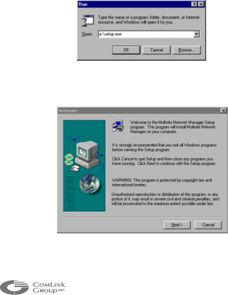
4.1 Installing the MNM
To install the MNM, follow these steps:
Insert the MNM Setup Disk 1 into drive A and select Run from the taskbar.
Figure 10 – Run Dialog Box
Type: a:\setup.exe and click OK (as in figure 1).
Figure 11 – Welcome Setup Dialog Box
The installation procedure might have to replace some files in use by other
programs. For this reason a welcome screen prompts you to exit setup and close all
25
_____________________________________________________________________________________________
Microflex AV/ADV/AVr/ADVr North-American user’s manual / Rev 1.2
running applications (figure 2). When all applications are closed continue setup by
clicking on <Next>.
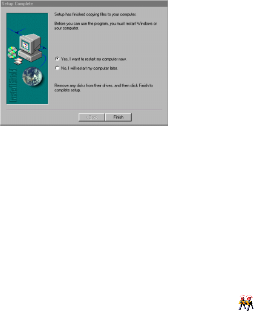
Read carefully the Release Note and then press <Next>.
The installation will start and install MNM to the default path C:\Program Files\MNM\.
Once completed, you will be asked to restart your computer, choose Yes and click
on <Finish>(figure 3).
Figure 12 – Setup Complete Dialog Box
4.2 Using Multisite Network Manager (MNM)
The MNM is designed to configure a Network. It can also be used to configure each
module individually before installing the network.
4.2.1 Launching the MNM Programmer
Launch Windows 95/98TM.
Connect the COMM Port used by the PC to one of the unit in the network. The
connection must be done on the Data Port #1.
____________________________________________________________________________
If you have ordered RS-485 signal level for Pan-Tilt-Zoom support, you will need a signal
converter plug-in module to convert the RS-485 signals to RS-232 signals for
communication with the computer on DATA 1.
____________________________________________________________________________
From the taskbar select Start | Programs | MNM.

26
_____________________________________________________________________________________________
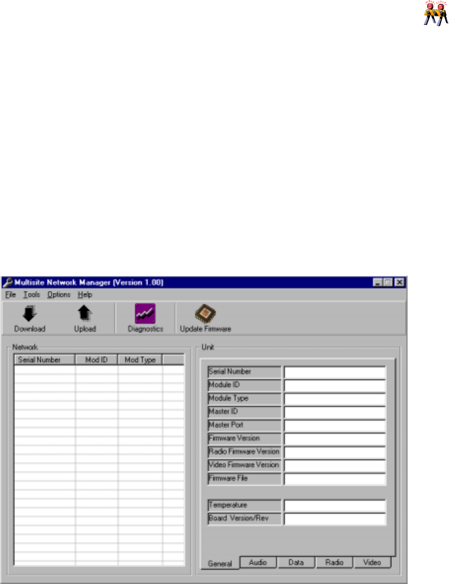
The MNM main window should then appear (figure 4).
Figure 13 – MNM Main view
MNM uses (by default) Comm Port 2 to communicate with the local module. To
change serial port select menu Options | Serial Port…and select the appropriate
Comm Port from the drop-down list and click OK (see figure 14).
Figure 14 – Communication Configuration Dialog Box
___________________________________________________________________
The Local Module is the Multisite unit connected directly to the computer’s serial
communication port. The Multisite Network Manager software uses a special escape
sequence that allow it to switch automatically the data port into a management port,
whatever the baud rate or the configuration of this port. For this reason, once the
computer is connected to a unit in the system, no additional manipulations are required for
the communication to begin.
___________________________________________________________________
27
_____________________________________________________________________________________________
Microflex AV/ADV/AVr/ADVr North-American user’s manual / Rev 1.2
____________________________________________________________________________
MNM may not work properly if two (2) or more Microflex are set in Master mode. There
must be a single Microflex set in master mode before using MNM.
____________________________________________________________________________
4.3 Main Operations
Only two simple operations are needed to configure a Multisite network: the
configuration download and the configuration upload.
The configuration download retrieves all the properties of each unit in the network.
All information is stored in a database and displayed to the user. Some
configurations are read-only and some others are read-write. To meet the
specifications of your application, you may modify the read-write properties as
required. Once the configuration is completed, the upload operation will send the
new configuration to each unit and save it permanently.
The MNM main window is divided into four distinct areas (figure 15): the menu bar,
the tool bar, the network list and the property tabs. Each of these parts is described
in the following sections.
Figure 15 – MNM Main view sections
Network
List
Property
Tabs
Tool Ba
r
Menu Ba
r
28
_____________________________________________________________________________________________
4.3.1 Network List
The Network List displays a general description of each unit present in the
Multisite network. Every row of the list contains the serial number, the module
identification number as well as the module type of a particular unit.
4.3.2 Unit Properties
Each unit may have its property set displayed in the property tabs. To see the
properties of a particular unit, simply select the unit in the network list by clicking
on it. The property tabs will automatically refresh itself.
From this point, you can browse through the different tabs related to the five
different property categories: General, Audio, Data, Radio or Video. Please refer
to section 4.2 for a complete description of each section.
4.3.3 Menu Bar
Four different menus are provided to help you complete your configuration:
• File
Open Firmware: Find and open firmware for download.
Exit: Quit Multisite Network Manager application.
• Tools
Download: Retrieve the configuration of all units in the network.
Upload: Transfer the new configuration from the computer to all the
units.
Diagnostics: Display a diagnostic window for the unit selected in the
network list (refer to section 4.5).
Update Firmware: Initiate the firmware update for the unit selected in the
network list (refer to section 4.6).
Factory Reset: Reset the properties of the selected unit to their factory
values (refer to section 4.7.1).
Unit Reset: Proceed to a software reset of the selected unit (refer to
section 4.7.2).
29
_____________________________________________________________________________________________
Microflex AV/ADV/AVr/ADVr North-American user’s manual / Rev 1.2
• Options
Serial Port: Displays the communication port configuration window.
• Help
Release Notes: Displays the special notes related to the actual software
release.
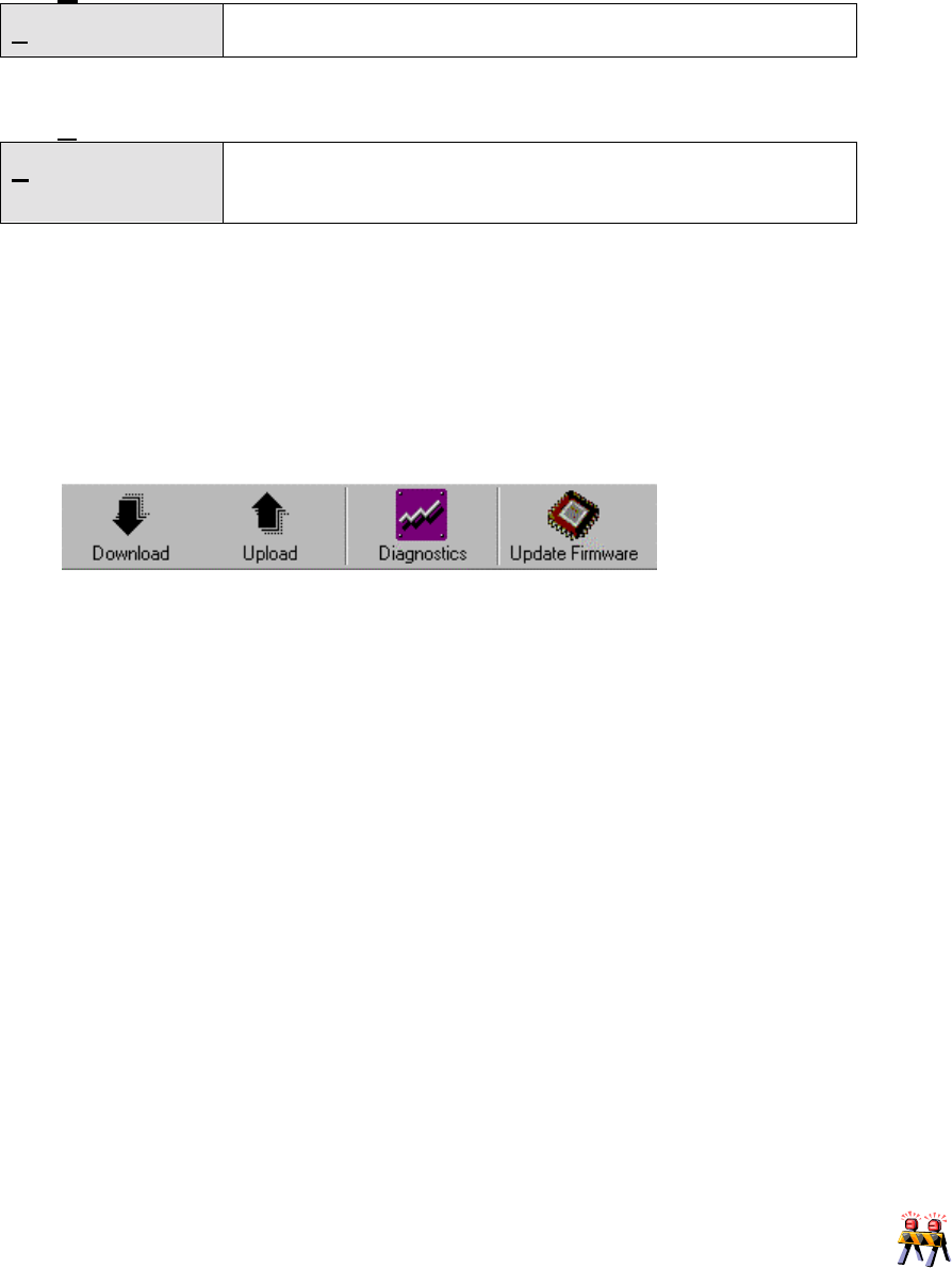
4.3.4 Tool Bar
The Tool Bar contains the four most important operations listed in the previous
section: Download, Upload, Diagnostics and Firmware Update. Please refer to
the appropriate section for additional information on those functions.
Figure 16 – MNM Tool Bar
4.4 Unit Properties
This section explains the different configuration items displayed in the four property
tabs.
4.4.1 General
• Serial Number (read-only)
This property displays the module’s embedded serial number. It is an exclusive
and read-only 12-digit number.
• Module ID (read-write)
An exclusive number, between 1 and 254, must be assigned to each module.
____________________________________________________________________________
All modules MUST have an exclusive and valid Module ID for normal network operation.
If you change the ID of a module in a network and download the network information
immediately after, not all network nodes may appear in the tree list. This is because the
Master node in the network may take up to 30 seconds to refresh, within its memory, the
new network architecture.
____________________________________________________________________________

30
_____________________________________________________________________________________________
• Module Type (read-only)
This property indicates the module type (Microflex or other) for the selected unit:
• Master ID (read-only)
The module identification number of the unit’s master is displayed here.
• Master Port (read-only)
The way the unit is connected to its master is provided with this property as
follows:
1) Drop & Insert: the unit is connected to the drop-and-insert (cabled) port
of its master
2) RF #x: the unit is connected to the RF port number x of its master.
• Firmware Version (read-only)
This label contains a string indicating the firmware version downloaded in the
selected unit.
• Radio Firmware Version (read-only)
This label contains a string indicating the Radio firmware version downloaded in
the selected unit.
• Video Firmware Version (read-only)
This label contains a string indicating the Video firmware version downloaded in
the selected unit.
• Firmware File (read-write)
Before performing a firmware update, the complete path of the firmware file must
be provided here.
• Temperature (read-only)
This property indicates the temperature of the selected Microflex
• Board Version/Rev (read-only)
This label contains a string indicating the Board Version and the Revision of the
selected unit (Ex: 1.0/A).
4.4.2 Audio
The following properties are provided for each available audio channels of a
selected unit.
• Module (read-only)
NONE when module does not support audio, FXS for 2-wire loop-start
subscriber, FXO for 2-wire loop-start line interface and Line Level for line level
audio hardware configuration.

31
_____________________________________________________________________________________________
Microflex AV/ADV/AVr/ADVr North-American user’s manual / Rev 1.2
• Compression (read-write)
The type of audio compression can be selected.
(a) LOW compression: ADPCM (32 kbps)
(b) MEDIUM compression: G.729 (8 kbps), voice activity detection and
comfort noise
• Extension (read-write)
Valid audio extensions between 1 and 899 must be assigned.
___________________________________________________________________
The Module ID number DOES NOT CORRESPOND to a telephone extension number.
Phone line extension numbers are assigned in the audio configuration tab of the
properties.
___________________________________________________________________
• Connection Extension (read-write)
In DOD mode (Direct Outward Dial) the extension of the paired phone line
appears in this window. In PABX and Auto Line Search modes, it is unused.
• Connection Type (read-write)
Three connection modes are available:
PABX: All phones (FXS modules) are accessible by dialing their own extension.
To reach an external line (FXO module), you have to dial ‘9’. This mode is an
emulation of a basic PBX phone system.
DOD: The DOD (Direct Outward Dial) mode is an emulation of a standard POTS
line. In this mode you have to connect a subscriber (FXS module) to a line
interface (FXO module). When this mode is selected, you must ensure that the
Connection Extension property is set properly for both connected units.
Auto Line Search: In this mode, the subscriber unit (FXS modules) connects to
the first available line interface (FXO module) as soon as placed off-hook.
___________________________________________________________________
To ensure that a DOD connection is valid, be sure that the two connected units refer to
each other in their Connection Extension properties.
___________________________________________________________________

32
_____________________________________________________________________________________________
4.4.3 Data
The following properties are provided for each available data channels of a selected
unit.
• Type (read-only)
(a) NONE when module does not support data transfer (all Multisite
modules support data except Linx).
(b) ASYNCHRONOUS for asynchronous transmissions
(c) SYNCHRONOUS for synchronous transmissions (not supported at
this time)
• Connection (Unit, Port) (read-write)
Displays the Module ID of the paired module when in point-to-point mode as well
as the port it is connected with. Select the connection from drop-down list or
simply write it down manually. The connection property MUST respect the (Unit,
Port) format.
• Baud Rate (read-write)
Select the required port data rate from the drop-down list. Maximum rate is
115200 bps for both data ports.
• Correction (read-write)
Enables or disables the error corrections feature. Error correction will only take
effect if both modules are, in a point-to-point link.
• Handshake (read-write)
Enables or disables hardware handshaking (RTS / CTS).
• Parity (read-write)
Enables or disables Data Parity (None / Odd / Even).
• Genex mode (read-write)
Enables or disables a Video Receiver Unit to emulate a Genex multiplexer. (Off /
On). This option must be selected for the MF24-ADVr when using the Microflex
in point-to-multipoint.
• PTZ Protocol (read-write)
Select the protocol between a Video Transmitter Unit and a Dome camera or PTZ
controller. This option must be selected only for Video Transmitter (MF24-ADV)
when using the Microflex in point-to-multipoint (or Genex mode ON).
Note: (Only available on data port 1)
___________________________________________________________________
In continuous data transmission application (non-stop stream), we strongly recommend to
configure user’s equipment connected on the data ports with two (2) stop-bit to avoid
buffer overflows over a long period of time. Flex and Microflex modules, are configured
33
_____________________________________________________________________________________________
Microflex AV/ADV/AVr/ADVr North-American user’s manual / Rev 1.2
with one (1) stop bit on their data ports.
___________________________________________________________________
4.4.4 Radio
• Selection (read-write)
NONE if no radio is present
RADIO 1 (INTERNAL) if one radio is present
• Status (read-only)
Not Detected if no radio is present
Detected if one radio is present
• Frequency (read-write)
Frequencies can be selected from the drop-down list or can be entered manually.
Frequency range is 2405 - 2484 MHz.
• PN code (read-write)
PN code can be selected from the drop-down list. Depending of the Bit Rate
selected the PN code list will change.
• Security code (read-write)
The Security code is a 4 characters Hexadecimal number (16 bit) , a value
between 0000 and FFFF must be assigned. The security code must be set to the
same value for all Multisite modules in a single network.
• Power (read-write)
You can select the radio output power from the provided drop-down list.
• Bit Rate (read-write)
You can select the radio bite rate from the provided drop-down list.
• RSSI Mode (read-write)
Select the appropriate RSSI display mode from the drop-down list:
MODE 1: Continuous RSSI
MODE 2: RSSI on valid receptions only
MODE 3: Continuous RSSI with maximum hold
MODE 4: RSSI on valid receptions with maximum hold
(ALWAYS SELECT MODE 2 under normal operation.)
• RSSI (read-only)
The value of the RSSI (Receive Signal Strength Indicator) when the “Download”
command was executed.

34
_____________________________________________________________________________________________
• Firmware Update (read-write)
When set to ‘On’ and Uploaded, this will update the firmware of the radio. It will
automatically return to ‘Off’ after the firmware update. This needs to be done only
one time after a Microflex radio firmware update.
___________________________________________________________________
Once the radio settings of a unit have been modified, it may not be capable to
communicate within the network. Always change the settings of all remote radios before
changing the settings of the base station.
___________________________________________________________________
4.4.5 Video
• Status (read-only)
<Not Detected> if no video sub-module is detected
<Detected> if the video sub-module is detected
• Video mode (read-only)
Displays the mode of the video module: ‘Transmitter’, ‘Receiver’ or ‘Unknown’ if
the video module was not detected by the Microflex.
4.5 Diagnostics
When installing a Multisite network, an important thing to check is the RF reliability.
To assist with this part of the installation process, a diagnostic window is provided in
MNM. To use it, simply select the unit to test in the network list and choose the
“Diagnostics” tool either in the menu bar or in the tool bar.
The following information will be displayed:
• Module ID
The identification number of the unit under test
• Serial Number
The unique serial number of the unit under test
• RSSI
The RSSI (Receive Signal Strength Indicator) of the RF signal
• Transmitted Packets
The number of transmitted packets in the packet error rate test
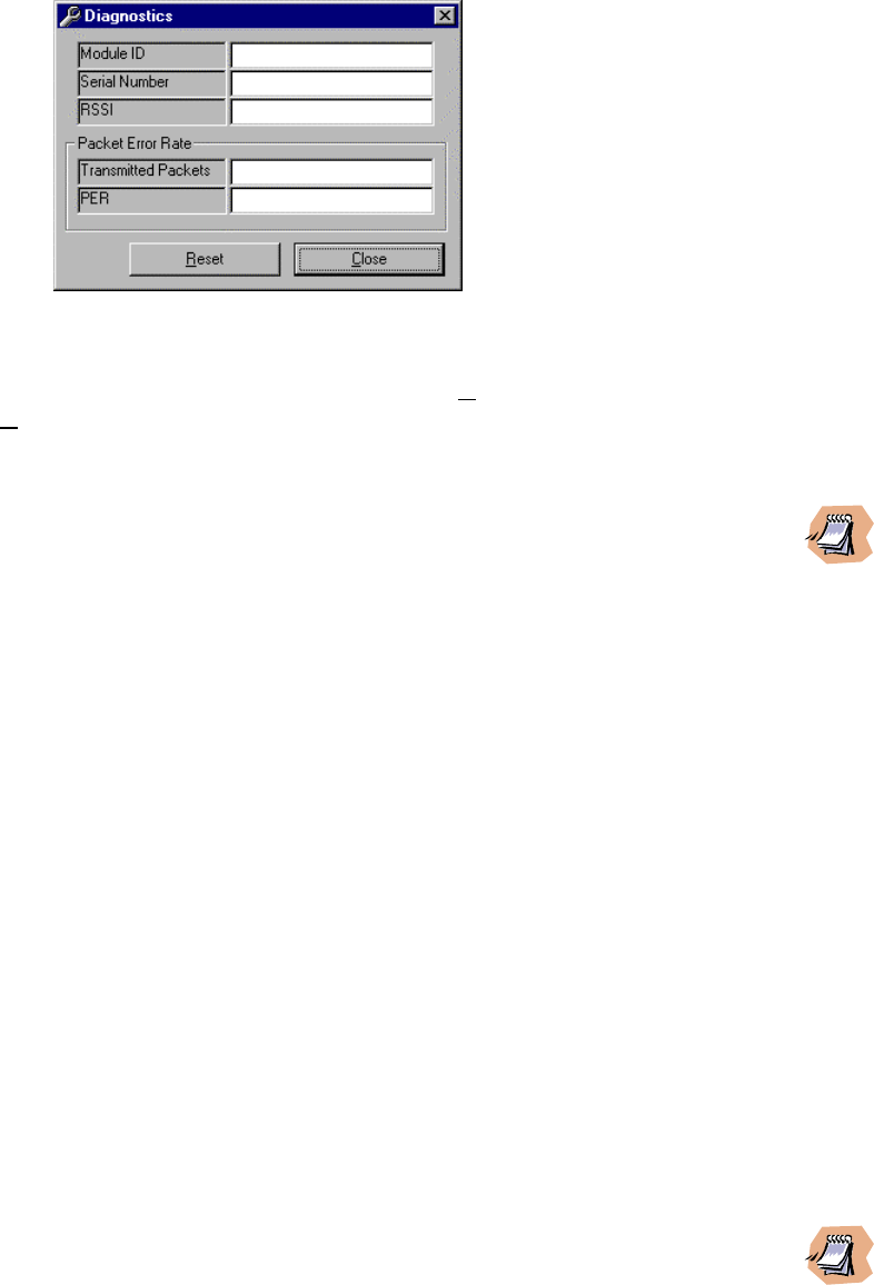
35
_____________________________________________________________________________________________
Microflex AV/ADV/AVr/ADVr North-American user’s manual / Rev 1.2
• PER (Packet Error Rate)
The error rate (number of errors / total number of packets) expressed in a
scientific format
Figure 17 – Diagnostic window
At any time, the test can be reset by clicking the “Reset” button or aborted by
clicking the “Close” button.
___________________________________________________________________
The diagnostic is not available on a Microflex in Master mode. A Microflex in Slave mode
must be selected to enable the diagnostic feature.
___________________________________________________________________
4.6 Firmware Update
MNM supports Microflex upgrades anywhere in the network. The Microflex A/AD
must have the following firmware modules loaded to be fully functional:
Microflex main program: Most recent version
Audio application program: Most recent version
Audio G.729AB CODEC: Most recent version
Radio main program: Most recent version
Radio loader program: Most recent version
To perform a firmware update of any of these modules, follow the few steps below:
(a) Select the unit to update in the network list (local or remote).
(b) Select the appropriate firmware file in the File menu either by browsing
the disk drives or by selecting a previously used filename.
(c) Proceed to the firmware update.
___________________________________________________________________
If the module has been set to loader mode (see Chapter 1) it will not be possible to see the
Microflex in the MNM list. In this case proceed to the firmware update without a module
selected. An error window will appear (figure 18). At this point, you can proceed with the
update if you are locally connected to the unit in loader mode. To do so, select “Yes”.

36
_____________________________________________________________________________________________
___________________________________________________________________
Figure 18 – Diagnostic window
4.7 Miscellaneous
4.7.1 Factory Reset (same as hardware switch SW1; see chapter 1)
This reset will bring back all factory settings including; module extension and
radio frequencies. For these reasons, a module reset this way may disappear
from the network list. You may need to configure this module locally. For the
reset to occur, you must select ‘Factory Reset’ from the drop down list and then
select ‘Unit Reset’ from this same list. Selecting ‘Factory Reset’ only will not
reset the module.
NOTE: The video settings are not affected by the Factory Reset.
4.7.2 Unit Reset (same as hardware switch SW2; see chapter 1)
This function selected alone (not preceded by ‘Factory Reset’) will perform a
software reset on the unit selected in the network list. Most of the time, it is going
to be used in the troubleshooting procedures.

37
_____________________________________________________________________________________________
Microflex AV/ADV/AVr/ADVr North-American user’s manual / Rev 1.2
CHAPTER 5 Using the KBD4000 in a Multisite Network
This Chapter describes the installation of a Pelco KBD4000
TM
keyboard controller (or
equivalent) in a Comlink Multisite
TM
video network. In a multi-point network, the keyboard
must be used
2
to select cameras, views, and other options.
The Pelco KBD4000 can also be used in a point-to-point network to support Quad View
display and future advanced options. Note however that in point-to-point, if a single
camera is used, the data port can be made transparent to support any Pan-Tilt-Zoom
protocol.
There are important facts the users should know about the utilisation of a KBD4000
TM
in a
Multisite Network:
• The KBD4000
TM
must be connected to a receiver unit (MF24-AVr/ADVr or FV).
• The KBD4000
TM
must be configured in <multiplexer mode> for proper operation.
• The video receiver (MF24-AVr/ADVr or FV) DATA1 serial port must be set to
“Genex Mode” to support the KBD4000 keyboard (see Chapter 4)
In ‘Genex Mode’, the MF24-Avr/ADVr (or FV) emulates a Pelco Genex
TM
multiplexer. The
receiver is therefore interchangeably referred to as a video receiver or multiplexer
throughout this Chapter.
2
ComLink has plans to release a Windows based software which emulates the KBD4000
TM
. Please
contact our Technical support team to have an update on the release date.

38
_____________________________________________________________________________________________
5.1 Configuring the KBD4000
TM
The KBD4000 must be pre-configured before being operational
3
. To setup the
KBD4000
TM
, follow these steps:
Remove the DIP switch cover plate from the rear of the keyboard and set the
switches to these positions:
1. Set switches 1, 2 and 3 to OFF (select the multiplexer mode of operation).
2. Set switch 4 to ON (to enable the non-polled communication mode).
3. Set switch 5 to OFF (unused).
4. Set switch 6 to OFF (to disable turbo pan feature).
5. Set switch 7 to ON (to address all cameras consecutively).
6. Set switch 8 to ON (to enable programming mode of the Multisite Video
Receiver).
5.2 Configuring the Microflex Video Receiver
To properly interface the KBD4000
TM
to the Multisite video receiver, DATA1 of the
Microflex video receiver must be configured properly using the MNM configuration
software (see Chapter 4). To do so, follow these steps:
1. Launch the Multisite Network Manager software (MNM).
2. Select the receiver unit in the left panel.
3. Click on the Data tab and select DATA1.
4. Configure the data port as follows: Connection = “none”, baud rate =
“9600bps”, Correction = ”Off”, handshake = “none”, parity = “odd”, Genex
mode = “On”.
5. Press the UPLOAD button to set the receiver with this new configuration.
____________________________________________________________________________
The video receiver DATA1 port supports RS-485 signal levels only (not RS-232). To
program the video receiver using MNM, you will need a signal converter plug-in module
to convert the RS-485 signals to RS-232 signals for communication with the computer on
DATA 1.
_____________________________________________________________________________________________
3
Comlink might already have completed this pre-configuration at the factory. In this case, ignore
these steps.
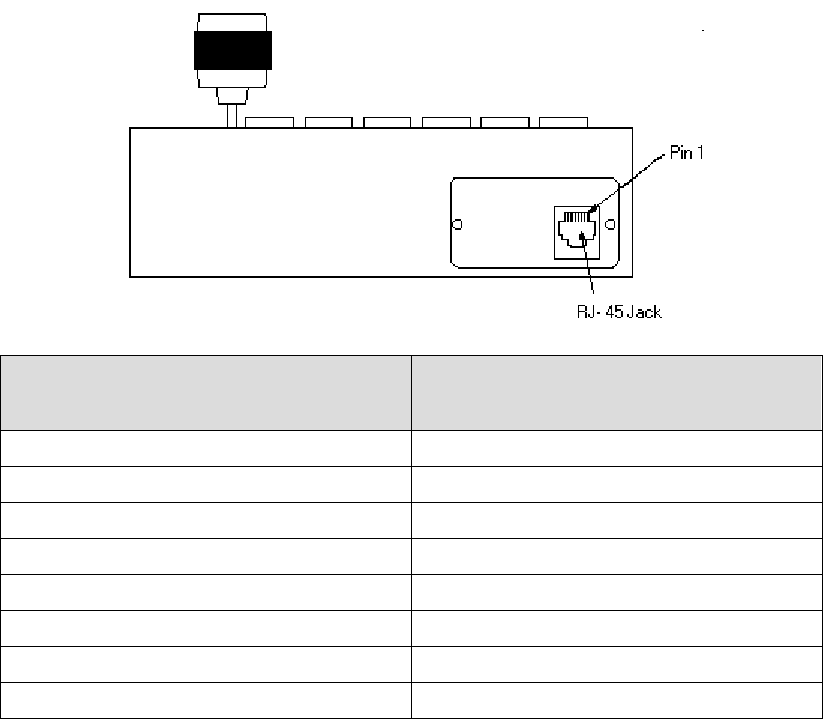
39
_____________________________________________________________________________________________
Microflex AV/ADV/AVr/ADVr North-American user’s manual / Rev 1.2
5.3 Connecting the KBD4000
TM
to the Microflex video receiver
KBD4000
TM
- RJ45 Pin-out (DTE) Microflex Receiver (DCE)
Interconnect Board (JP16 or JP17)
1
Pin 1 : TX+ Pin 1: TX+
Pin 2 : TX- Pin 2: TX-
Pin 3 : 12 VAC/DC NON POLAR
2
Pin 4 : 12 VAC/DC NON POLAR
2
Pin 5 : GND Pin 5: GND
Pin 6 : No Connect
Pin 7: RX- Pin 4: RX-
Pin 8: RX+ Pin 3: RX+
1
For MF24-AVr/ADVr, DATA1 is referred to as JP16 on the interconnect board. For
FV module, DATA1 is referred to as JP17. Note that on both interconnect board
models, Pins 1-5 are counted from left to right.
2
A 12VAC power supply on Pins 3 and 4 or a 12VDC on Pin 3 and pin 5 (ground) must be
supplied.
5.4 Connecting the KBD4000
TM
to multiple Microflex receivers
It is possible to use a single KBD4000
TM
to control two (2) or more video
receivers (any of three models). To support this, proceed as follows:
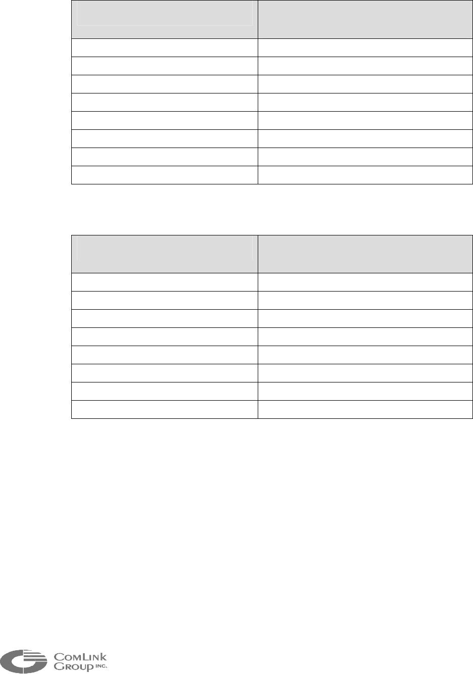
40
_____________________________________________________________________________________________
Select one of the video receivers (anyone) and connect it as follows:
KBD4000
TM
- RJ45 Pin-out (DTE) Microflex Receiver (DCE)
Interconnect Board (JP16 or JP17)
1
Pin 1 : TX+ Pin 1: TX+
Pin 2 : TX- Pin 2: TX-
Pin 3 : 12 VAC/DC NON POLAR
2
Pin 4 : 12 VAC/DC NON POLAR
2
Pin 5 : GND Pin 5: GND
Pin 6 : No Connect
Pin 7: RX- Pin 4: RX-
Pin 8: RX+ Pin 3: RX+
Connect the other receivers as follows:
KBD4000
TM
- RJ45 Pin-out (DTE) Microflex Receiver (DCE)
Interconnect Board (JP16 or JP17)
1
Pin 1 : TX+ Pin 1: TX+
Pin 2 : TX- Pin 2: TX-
Pin 3 : 12 VAC/DC NON POLAR
2
Pin 4 : 12 VAC/DC NON POLAR
2
Pin 5 : GND Pin 5: GND
Pin 6 : No Connect
Pin 7: RX-
Pin 8: RX+
1
For MF24-AVr/ADVr, DATA1 is referred to as JP17 on the interconnect board. For FV
module, DATA1 is referred to as JP16. Note that on both interconnect board models,
Pins 1-5 are counted from left to right.
2
A 12VAC power supply on Pins 3 and 4 or a 12VDC on Pin 3 and pin 5 (ground) must
be supplied.

41
_____________________________________________________________________________________________
Microflex AV/ADV/AVr/ADVr North-American user’s manual / Rev 1.2
5.5 Using the KBD4000
TM
in a Microflex Video Network
The KBD4000
TM
is an essential tool in a Multisite video network. It allows you to
configure the multiplexer options (title, date, time etc.), to select the cameras to
display, to perform the pan, tilt and zoom functions (if PTZ drivers are used).
The multiplexer automatically selects the most common operating parameters.
However, some minimal programming may be required in order for your system to
operate properly. The next sections describe all KBD4000
TM
functions supported by
the Microflex.
5.5.1 Microflex ID’s
In a Multisite video network, the unit ID must be set to a specific range.
STEP 1 A Microflex video receiver (MF24-AVr/ADVr or FV) must have a
unit ID between 1 and 16.
STEP 2 A Microflex video transmitter (MF24-AV/ADV) must have a unit ID
between 1 and 63.
To modify the unit ID, refer to Chapter 4 (using the MNM configuration software).
5.5.2 Camera selection in Full Screen Display
To enter the Full Screen Display mode, push the < > key once.
To select a camera in Full Screen Display mode, you must type the camera ID
number, then the <CAM> key.
Example: to select camera 66, type: <66>, <CAM>.
___________________________________________________________________
The camera ID is calculated from the Microflex transmitter unit ID (1 to 63) and with
camera input (1 to 4): CAM ID = (UNIT ID – 1)*4 + Tx cam input.
For example, to select the camera input 2 on the Multisite transmitter unit 17, you must
use CAM ID = 66 ( (17-1)*4 + 2).
To select NO CAMERA, set CAM ID to 256:
<256>,<CAM>
Since the Genex protocol supports CAM IDs between 1 and 252, the Microflex video
transmitters ID’s must be between 1 and 63. Unit ID’s must be configured with the
MNM configuration software.
___________________________________________________________________

42
_____________________________________________________________________________________________
5.5.3 Multiple Camera display
To enter the Quad View mode, press once on the < > key. Please note that
Nine and sixteen camera display mode are not supported at this time.
To select cameras in this view follow these steps:
1) In Quad View mode, hold the < > key for 3 seconds or more. A bar will
appear in the first camera location (the title of the camera in the selected
display position will be blinking) indicating that you are in the Programming
mode.
2) Use the joystick to move to each camera location in the quad view.
3) When the camera location that you desire is highlighted (the title is blinking),
choose the desired camera by pressing its ID number followed by the <CAM>
key.
4) Repeat step 2 and 3 for all display positions.
5)
To exit the Programming mode, use the joystick to move the bar off the
screen. You must exit the Programming mode to be able to switch to the Full
Screen View mode.
5.5.4 Menus
! Basic Set-up menu (VIEW Key)
The Basic Set-up Menu allows to program the main system parameters. To enter
this menu, press the <VIEW> key for 3 seconds or more (you may need to type a
password if one has been assigned previously). The Basic Set-up Menu will
appear. The cursor (“>>” indicator) points to the currently selected menu item.
Use the joystick to move between items on the screen. When the menu item you
desire is selected, press the <OPEN> key to enter the options menu.
ITEMS SUPPORTED
Time and Date
Set the current time and date. The time uses a 24-hour clock.
Time Display
ON – Display the time on the monitor.
OFF – The time is not shown on the monitor (default).
Title Display
ON – Display camera titles on the monitor (default).
OFF – Camera titles are not shown on the main monitor.

43
_____________________________________________________________________________________________
Microflex AV/ADV/AVr/ADVr North-American user’s manual / Rev 1.2
Camera setup
Go to the CAMERA SETUP menu.
Save configuration
Save the current camera configuration (view, camera number, camera name). If
the system reboot, it will reboot with the last saved configuration.
Help
Go to the HELP menu.
Advanced setup
Go to the ADVANCED SYSTEM SETUP menu.
! Advanced Set-up Menu
To program the advanced parameters, enter the System Setup Menu: press the
<VIEW> key for approximately three seconds (type the password if one has been
assigned). The System Setup Menu appears. The cursor (“>>” indicator) points to
the currently selected menu item. Use the joystick to move to the ADVANCED
MENU item. Press the <OPEN> key. The Advanced System Setup menu
appears.
ITEMS SUPPORTED
Date format
Set the format for displaying the date on the monitor.
Password
Enables or disables password control to access programming menu.
Exit
Return to the Basic Setup menu.
! Camera Set-up Menu
To program the camera parameters, enter the System Setup Menu: press the
<VIEW> key for approximately three seconds (type the password if one has been
assigned). The System Setup Menu appears. The cursor (“>>” indicator) points to
the currently selected menu item. Use the joystick to move to the CAMERA
SETUP MENU item. Press the <OPEN> key. The Camera Setup menu appears.

44
_____________________________________________________________________________________________
ITEMS SUPPORTED
Camera number
Select the camera you want to configure. Press the <OPEN> key and select a
camera number. To select a camera, enter the camera ID number, then the
<CAM> key (<1>,<CAM> for camera 1).
Camera title
Modify the title for the selected camera. Press the <OPEN> key, then select
characters for your title. To select characters, move the joystick up and down. To
switch between characters move the joystick left and right.
Reset values to default
Reset title to default.
Exit
Return to the Basic Setup menu.
! Help Menu
The Help menu is accessed from the Basic Set-up menu. Use the joystick to
select HELP. Press the <OPEN> key. The HELP menu appears
5.6 Pan, tilt and zoom functionality
The keyboard allows the user to operate a PTZ controller which supports Pelco’s D
protocol. To connect the camera to the Microflex video transmitter (MF24-AV,
MF24-ADV), follow this table.
PTZ Controller Signals (DTE) Microflex Transmitter (DCE)
Interconnect Board (JP17)
1
TX+ (optional) Pin 1: TX+
TX- (optional) Pin 2: TX-
GND Pin 5: GND
RX+ Pin 3: RX+
RX- Pin 4: RX-
1
DATA1 on the interconnect board of the MF24-AV/ADV is referred to as JP17. Note that
on both interconnect board models, Pins 1-5 are counted from left to right.

45
_____________________________________________________________________________________________
Microflex AV/ADV/AVr/ADVr North-American user’s manual / Rev 1.2
The pan, tilt and zoom functionality is easy to use in a Multisite network. From the
Full or Quad View mode, you must type the camera ID number followed by the
<CAM> key. Then, just move the joystick up and down for pan control, left and right
for tilt control, and twist it for zoom control.
5.7 Password
You can program the multiplexer to request a password for access to programming
menus. The password is enabled in the Advanced System Setup menu (refer to the
Advanced System Setup section).
The universal password is 3916 and cannot be changed. This password must be
entered whenever one is requested. The password is entered from the keyboard by
pressing each number followed by the CAM key: <3>, <CAM>,<9>, <CAM>, <1>,
<CAM>, <6>, <CAM>.
5.8 Using one KBD4000
TM
and multiple video receivers.
To select the receiver you want to configure: enter the receiver ID (a number
between 1 and 16) and then press the UNIT key. Ex: <6>, <UNIT>.
Once a receiver is selected, all the commands will be send to it until another
receiver is selected.
To select all the receivers: enter <0> and then press the <UNIT> key.
____________________________________________________________________________
The module ID of the Microflex video receiver (MF24-AV/Avr or FV) must be set between 1
and 16 to work properly. After a power-down sequence or software reboot all the
receivers will respond to the keyboard commands.
____________________________________________________________________________
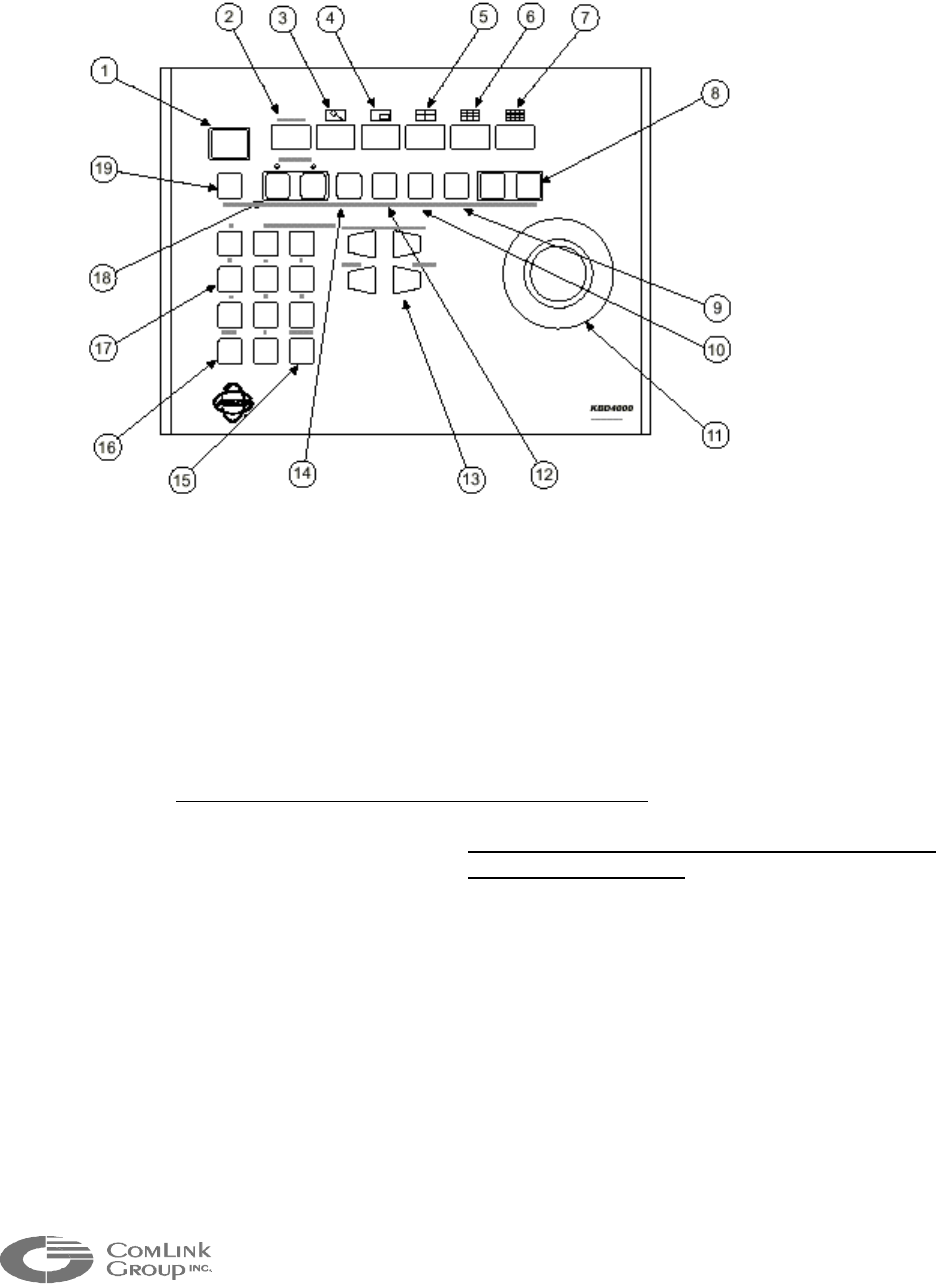
46
_____________________________________________________________________________________________
5.9 KBD4000
TM
keyboard definitions
1. LED DISPLAY: Displays the address of the multiplexer (from 1-16) with which
the keyboard is communicating. This display is only valid when
addressing camera through the multiplexer. Since consecutive
addressing is used for the Multisite Series, this display can be
ignored.
2. LIVE/VCR KEY: unused.
3. ZOOM KEY: unused.
4. PIP: Press once to set the receiver view to full screen.
5. FOUR-CAMERA DISPLAY KEY: Press once to display a group of four cameras
on the main monitor. From the Quad View,
press it 3 seconds to be able to select cameras.
For more information, read section 5.5.3.
6. NINE-CAMERA DISPLAY KEY: unused.
7. 16-CAMERA DISPLAY KEY: unused.
8. AUXILIARY KEYS: unused.
9. PRESET KEY: 1: Sends a camera to a preset: enter the preset number and then
press this key once. 2: Programming presets: enter the preset
number and then press this key for 5 seconds (Note: the PTZ
controller must support Pelco protocol D or P preset definition)

47
_____________________________________________________________________________________________
Microflex AV/ADV/AVr/ADVr North-American user’s manual / Rev 1.2
10. PATTERN KEY: unused.
11. PTZ FUNCTION JOYSTICK: Variable-speed, bi-directional joystick for pan/tilt
control. Twisting head for zoom control. Also used
to move the cursor in the different menus.
12. VIEW KEY: Press 4 seconds to enter programming mode for the Receiver. For
more information, read section 5.5.4.
13. LENS CONTROL KEYS: Control Camera lens, iris and focus functions. The Open
key is also used to select item in the different menus.
14. SEQ KEYS: (not supported at this time). Starts/stop a sequence.
15. CLEAR KEY: Press to clear a numeric entry.
16. CAM KEY: Select a camera: enter the camera number (a number between 1 and
252 in consecutive addressing mode) and then press this key. To
select NO CAMERA, you must enter: <256>, <CAM> key.
17. NUMBER PAD: Enter numbers.
18. MONITOR KEYS: unused.
19. UNIT KEY: This key is used to select the receiver unit you want to operate with the
keyboard. For example, if you want to operate the Receiver 12
(Microflex unit ID 12), press <12> + <UNIT> key. For more info, read
section 5.8.

48
_____________________________________________________________________________________________
APPENDIX A - Factory Default Configuration
If the Microflex fails to respond after programming it with the MNM configuration software,
it can be reset to a factory default configuration by activating the reset switch (SW1) on
the main electronics board (see Chapter 1) or by using the MNM software.
The Microflex is programmed at the factory with the following configuration (this is based
on version 0.07A):
• Module ID : 000
• Module Type : Microflex
Note : The module must be set to a valid module ID to see the remaining
of the configuration. Following the proper assignment of an ID (via the
upload sequence) downloading the information will display the rest of the
unit configuration.
• Firmware Version : Will vary
• Radio Firmware : Will vary
• Data Port 1 Settings
TYPE : Asynchronous
CONNECTION : NONE
DATA RATE : 9 600 BAUD
PARITY : None
HANDSHAKE : Disabled
ERROR CORRECTION : OFF
GENEX MODE : OFF
• Data Port 2 Settings
TYPE : Asynchronous
CONNECTION : NONE
DATA RATE : 9600 BAUD
PARITY : None
HANDSHAKE : Disabled
ERROR CORRECTION : OFF
• Audio Port 1 Settings
MODULE : <FXS>, <FXO>,<Line Level> or <NONE>
(depending on option ordered)
EXTENSION : 000
COMPRESSION : LOW
CONNECTION EXTENSION : 0
CONNECTION TYPE : PABX
• Audio Port 2 Settings
MODULE : <FXS>, <FXO>,<Line Level> or <NONE>
(depending on option ordered)
EXTENSION : 000
49
_____________________________________________________________________________________________
Microflex AV/ADV/AVr/ADVr North-American user’s manual / Rev 1.2
COMPRESSION : LOW
CONNECTION EXTENSION : 0
CONNECTION TYPE : PABX
• Radio Settings
SELECTION : RADIO 1 (internal)
STATUS : DETECTED
FREQUENCY : 2442 MHz
PN CODE : 1
SECURITY CODE : F3A0
RADIO POWER : 24 dBm
BIT RATE : LOW
RSSI MODE : 2
FIRMWARE UPDATE : OFF
• Radio Settings
STATUS : DETECTED
VIDEO MODE : <TRANSMITTER>,<RECEIVER> OR
<UNKNOWN>

50
_____________________________________________________________________________________________
APPENDIX B - Telephone System Operation
This paragraph is a reference on how to use the Multisite telephone system under
different operation mode. Each Microflex can be programmed to support one of two
telephone modes; (1) PABX mode and (2) DOD (direct outward dial). It is also possible to
combine these two dialing modes in a Multisite network.
• PABX MODE FEATURES:
All Microflex modules programmed for PABX mode must dial “9” to obtain an
external telephone line unless the auto-dial check box is selected.
When dialing “9”, the Microflex (FXS) will contact the Microflex (FXO) with the
lowest ID number. If it is busy, it will contact the next Microflex (FXO) with the
lowest ID number and so on until it tries all Microflex FXO extensions. If there
are no extensions available a busy signal will be played back (the outside line
search takes less than 1 second).
For incoming calls on the FXO line, a stutter tone is played. By dialing the correct
Microflex (FXS) extension the call will be connected to the Microflex extension.l
Internal calls between Microflex (FXS) are supported without tying up external
telephone lines by dialing the appropriate extension number.
• DOD MODE FEATURES:
To operate in DOD mode, a Microflex (FXS) must be associated with a single
Microflex (FXO or FXS).
There is no need to dial “9” from a Microflex (FXS) since it is a direct line.
All incoming call on the external FXO line are directly transferred to the
associated Microflex (FXS).
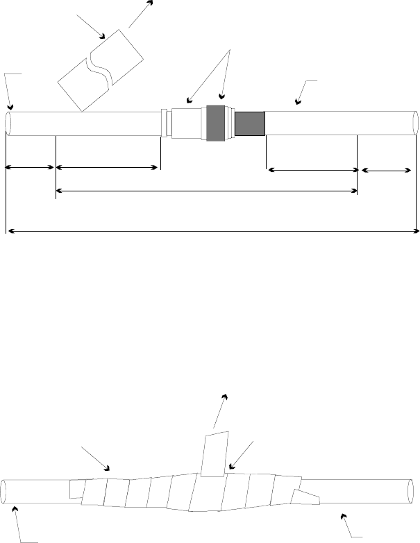
51
_____________________________________________________________________________________________
Microflex AV/ADV/AVr/ADVr North-American user’s manual / Rev 1.2
APPENDIX C - Weatherproofing Coaxial Connections
The Microflex are normally mounted outside. Weatherproofing of coaxial connections is
required for successful long-term operation.
Most antenna problems are caused by coaxial cable connections that loosen due to
vibration, allowing moisture to penetrate the connector interface. ComLink recommends
that all outdoor cable connections be weatherproofed using a procedure similar to the one
described below. To facilitate the task, the sealant tape is supplied with each antenna
shipped (the customer is responsible for providing the electrical tape).
STEP 1.
Beginning as shown in Figure 19, by overlapping half-width, wrap sealant tape over
entire connection.
Cable
Mated connectors, typical
Cable
Sealant tape
SEALANT TAPE
COVERAGE AREA
COVERAGE AREA
ELECTRICAL TYPE
1“ 1“
1 ½ - 2“ 1 ½ - 2“
Figure 19 - Stretch to elongate sealant tape while wrapping over connection
STEP 2.
Gently press on the sealant tape, forming it to the connection, itself and the cable
jackets, as shown in Figure 20.
Cable Cable
Sealant tape over entire
Connection
Electrical tape (not supplied)
Figure 20 - Stretch to elongate electrical tape while wrapping over sealant tape
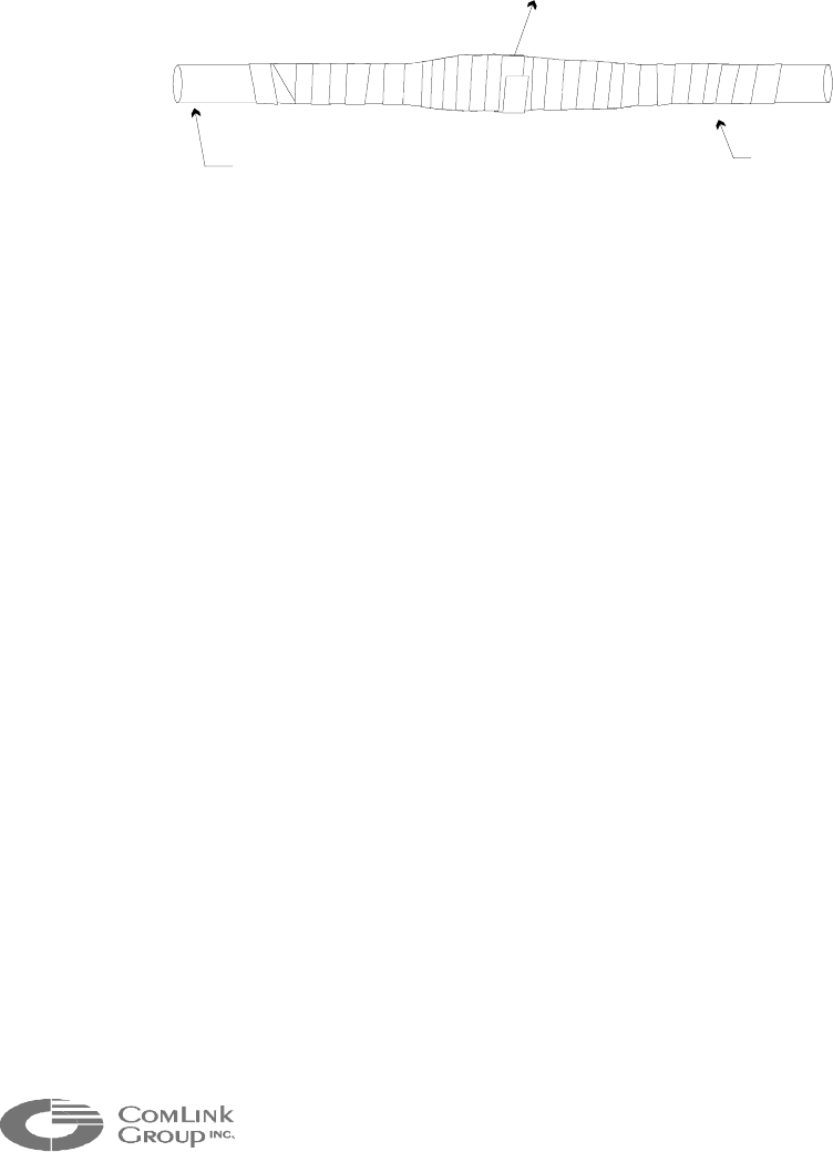
52
_____________________________________________________________________________________________
STEP 3.
By overlapping half-width, wrap electrical tape (not supplied) over the entire sealant
tape connection. While stretching tape, begin at center of formed sealant tape and
wrap towards one end approximately one inch beyond end of sealant tape.
Insure tight electrical tape coverage onto cable jacket. Without breaking electrical
tape, reverse direction and wrap to other end, again extending approximately one
inch beyond end of sealant tape. Again insure tight coverage onto cable jacket.
Reverse direction again and wrap electrical tape to center of connection and stop.
Cable Cable
Electrical tape formed over
entire connection
Figure 21 - Electrical tape wrapped tightly against cable jacket, typical both ends

53
_____________________________________________________________________________________________
Microflex AV/ADV/AVr/ADVr North-American user’s manual / Rev 1.2
APPENDIX E - Switching from RS-232 to RS-485 for a
MF24-ADV/ADVr
If you have ordered a Microflex with an RS-485 port, DATA1 has been factory configured for
RS-232 operation and 2 RS-485 chips have been shipped separately in an ANTISTATIC bag.
This is because you may need to program the Microflex locally via the DATA1 port and using
the MNM configuration software prior to or during installation.
Once you have completed the configuration of the Microflex, proceed as follows to switch the
data port to RS-485 mode:
1. Power the unit OFF, then wait at least 1 minute.
2. Insert the 2 RS-485 chip at positions U4 and U7 on the interconnection board (see
illustration on next page for exact chip location)
NOTE: Observe STATIC PRECAUTIONS when handling the RS-485 chips
3. Change the jumpers JP4,5,7,8,9 according to the table below (see illustration on
next page for exact jumper location).
4. Install jumpers at JP2 & JP3 to terminate the RS-485 receive line (jumpers are
included with the RS-485 chip package).
EIA232 Mode EIA485 Mode Comments
JP2
REMOVED INSTALLED
1
120 Ohm termination of Tx pair
JP3
REMOVED INSTALLED
1
120 Ohm termination of Tx pair
JP4
Position 1-2 Position 2-3 EIA232/485 SELECT
JP5
Position 1-2 Position 2-3 EIA232/485 SELECT
JP7
Don’t care 1-2 = Rx always ON
2-3 = Rx keyed ON/OFF
2
Rx Driver enable control
JP8
Position 1-2 Position 2-3 EIA232/485 SELECT
JP9
Position 1-2 Position 2-3 EIA232/485 SELECT
1 The jumpers for JP2 & JP3 are in the same bag as the RS-485 chip.
2 This position is not required unless you are using bi-directional control and multiple
RS-485 modules on the same cable.
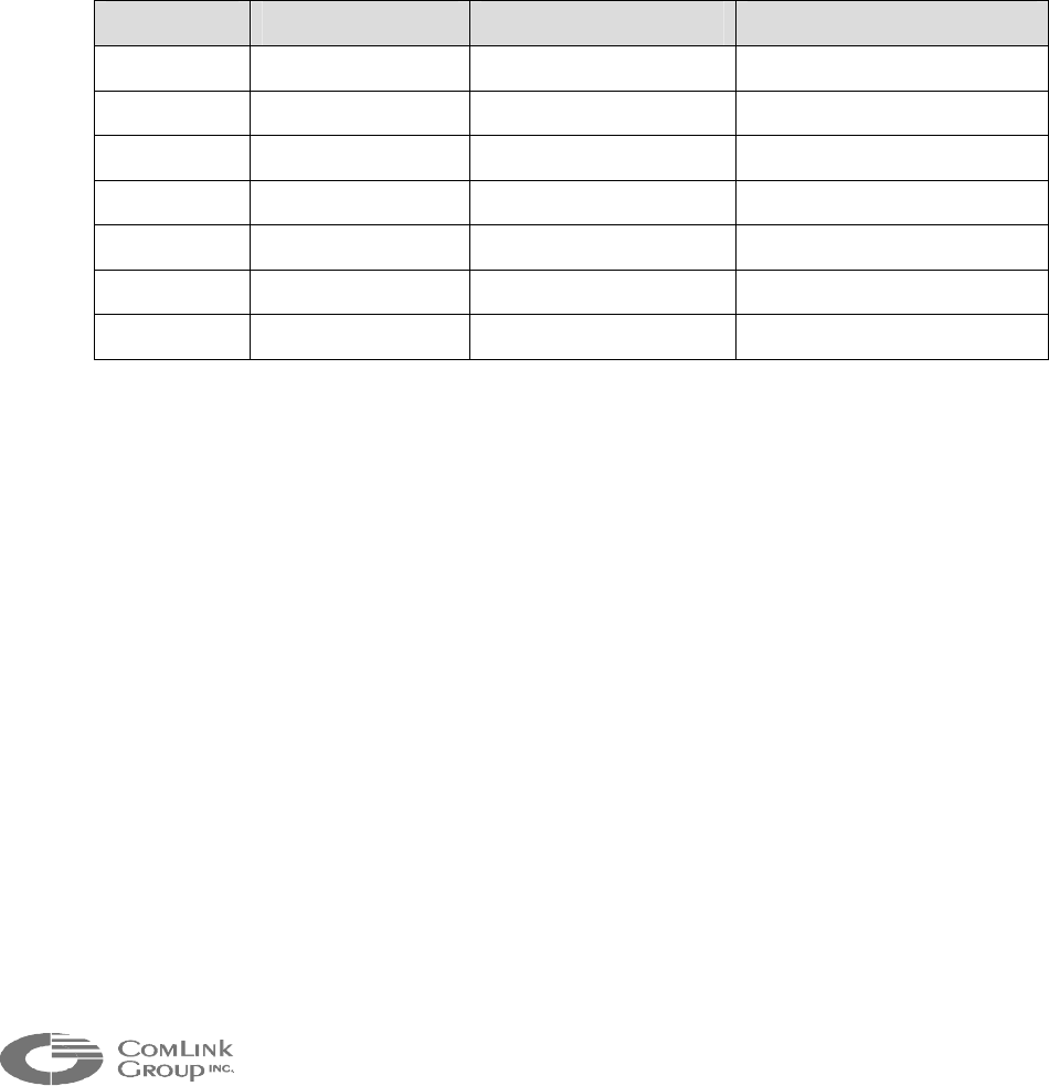
54
_____________________________________________________________________________________________
APPENDIX F - Switching from RS-232 to RS-485 for an
FV module
If you have ordered an FV module, DATA1 has been factory configured for RS-485 operation.
If you require to download a new video firmware in the FV module, you will need to set-up the
data port in RS-232 mode to use the MNM configuration software. To do so, proceed as follows
to switch the data port to RS-232 mode:
1. Change the jumpers JP7, 8, 9,11,12 according to the table below (see illustration
on next page for exact jumper location).
2. Remove jumpers JP3 & JP4.
EIA232 Mode EIA485 Mode Comments
JP3
REMOVED INSTALLED 120 Ohm termination of Tx pair
JP4
REMOVED INSTALLED 120 Ohm termination of Tx pair
JP7
Position 1-2 Position 2-3 EIA232/485 SELECT
JP8
Position 1-2 Position 2-3 EIA232/485 SELECT
JP9
Position 1-2 Position 2-3 EIA232/485 SELECT
JP11
Position 1-2 Position 2-3 EIA232/485 SELECT
JP12
Position 1-2 Position 2-3 EIA232/485 SELECT
3. When you have finished configuring your unit with MNM, Re-install all jumpers as
they were before to set the unit back to RS-485 mode (see table).

55
_____________________________________________________________________________________________
Microflex AV/ADV/AVr/ADVr North-American user’s manual / Rev 1.2
APPENDIX G – Connecting to leased lines
The Line Level interface is a single ended 600 Ohms – 0 dBm interface. It is not
designed to drive leased/dry lines. A 600 Ohm coupling transformer must be used for
differential application.
Typical example :
AUDIO IN (TO JP19 PIN 4)
GROUND (TO JP19 PIN 6)
AUDIO OUT (TO JP19 PIN 5
)
GROUND (TO JP19 PIN 6)
leased line (twisted pairs)
IN
OUT